Vimtag Technology IPC Cloud Camera User Manual FI 361 Ver1 0 1
Vimtag Technology Co., Ltd Cloud Camera FI 361 Ver1 0 1
UserManual.wiki
>
Vimtag Technology
>
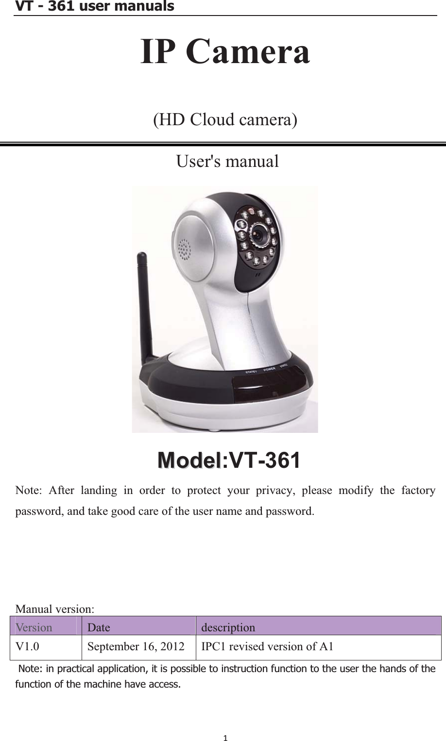
IPC User Manual
User Manual
Navigation menu
Upload a User Manual
Namespaces
Wiki Guide
HTML
PDF
Info
Views
User Manual
Discussion / Help
Navigation