Vimtag Technology IPC Cloud Camera User Manual FI 361 Ver1 0 1
Vimtag Technology Co., Ltd Cloud Camera FI 361 Ver1 0 1
User Manual
VT - 361 user manuals
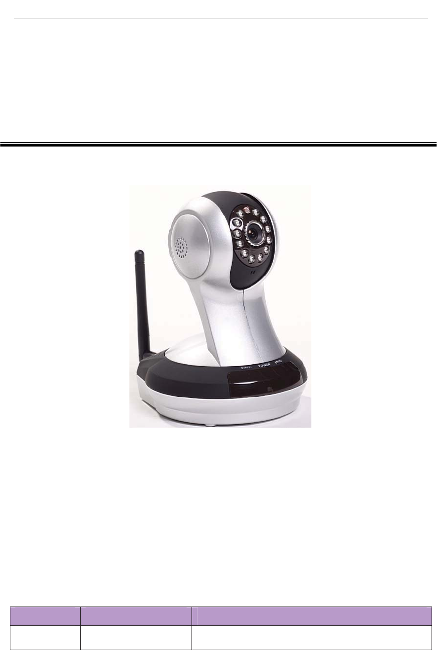
IP Camera
(HD Cloud camera)
User's manual
M
Mo
od
de
el
l:VT-361
Note: After landing in order to protect your privacy, please modify the factory
password, and take good care of the user name and password.
Manual version:
Version Date description
V1.0 September 16, 2012 IPC1 revised version of A1
Note: in practical application, it is possible to instruction function to the user the hands of the
function of the machine have access.
1

VT - 361 user manuals
Content
Product Overview .............................................................................................................................4
Packing List. .............................................................................................................................4
System Requirements................................................................................................................4
Introduction............................................................................................................................... 4
Features.....................................................................................................................................5
Overview of the Hardware view ...............................................................................................6
Installation.........................................................................................................................................7
Hardware Installation................................................................................................................7
Camera Installation Wizard.......................................................................................................8
Wireless Installation Considerations.......................................................................................11
Home page ......................................................................................................................................13
One .Camera status bar: ..........................................................................................................13
Two. Image settings and PTZ control bar. ..............................................................................14
The recorded single frequency................................................................................................15
Playback..........................................................................................................................................15
Log ..................................................................................................................................................16
Management....................................................................................................................................17
One. Product information:..................................................................................................17
Two . User ...............................................................................................................................18
Equipment nickname.......................................................................................................18
Password: ........................................................................................................................18
Three. Media stream: ..............................................................................................................19
Stream .............................................................................................................................19
Image: .............................................................................................................................19
Framerate ........................................................................................................................19
Four. Network .........................................................................................................................20
1. Ethernet:......................................................................................................................20
2. Wireless Network:.......................................................................................................21
Five. Servers ...........................................................................................................................22
IP address ........................................................................................................................22
Six. Media transfer:.................................................................................................................23
Transfer Protocol:............................................................................................................23
Seven. PTZ..............................................................................................................................23
Speed...............................................................................................................................24
Eight. OSD:.............................................................................................................................24
Display Name..................................................................................................................25
Display date.....................................................................................................................25
Date format .....................................................................................................................25
Display week...................................................................................................................25
NineˊAudio:..........................................................................................................................26
Speaker............................................................................................................................26
Microphone .....................................................................................................................26
TenˊSD card:.........................................................................................................................27
2

VT - 361 user manuals
Status............................................................................................................................... 27
Capacity: .........................................................................................................................27
Usage: .............................................................................................................................27
Eleven. Alarm: ........................................................................................................................28
External input arming:.....................................................................................................28
IO linkage:.......................................................................................................................28
Twelve.Date/Time ...................................................................................................................29
Date:................................................................................................................................29
Time: ...............................................................................................................................29
Automatically synchronized with the time server:..........................................................29
Time server address:........................................................................................................29
Thirteen .System maintenance: ...............................................................................................30
Online upgrade................................................................................................................30
Restore the default settings: ............................................................................................30
Restart the device:...........................................................................................................30
Troubleshooting ..............................................................................................................................31
Wireless Infrastructure ....................................................................................................................34
Wireless Security ............................................................................................................................36
Specifications..................................................................................................................................37
3

VT - 361 user manuals
Product Overview
Packing List.
9 1 set of network cameras
9 An Ethernet cable
9 A 5V power adapter
9 Disc 1 piece
9 Quick Installation Guide
9 Bracket (base) and mounting set
9 A Wireless antenna
9 A warranty card
Note: The use of non-product rated voltage power supply, will result in
equipment damage, and does not enjoy the product warranty.
Of above items if something is missing, contact your dealer.
System Requirements
• With Microsoft Windows ® 7, Vista ®, XP ®, Mac OS or Linux system
computer
• CPU clocked at 1.3G or higher, at least 128MB of RAM
• Internet Explorer 7 or later, Firefox 3.5 or later, Safari 4 and Chrome 8.0 or
later.
Introduction
Congratulations on your purchase of the Cloud CAMERA.The Cloud CAMERA has
multiple functions, is dedicated to the small office and home solutions.Unlike
traditional IP CAMERA, Cloud CAMERA has a complete system with built-in CPU
and web server, can transmit high-quality images, the implementation of the security
monitoring. Cloud CAMERA from any computer or laptop via a local network or the
4

VT - 361 user manuals
Internet using a web browser to access and control; their installation is simple,
intuitive user-friendly WEB interface settings, can be combined with 802.11b
wireless network perfect . The Cloud CAMERA also has a remote monitoring and
motion detection function, making it a complete, cost-effective home security
solution.
Features
9 Can support H.264/MPEG4/MJPEG stream, suitable for Local, Internet access as
well as cross-platform;
9 CMOS sensor, support 1280 * 720,640 * 360 , 320 * 180,160 * 90 real-time
video encoding;
9 Support the smartphone anywhere to watch the video screen, support Windows
Phone, Android system smartphone / IPHONE phone / IPAD devices to ensure that
the image smooth / no stumble.. (25 image transmission can watch 720P HD image);
9 P2P technology-free configuration plug-and-play (no need to do port mapping ,
DNS, IP address settings)
9 A key WPS easy wireless connectivity, privacy features, arm function.
9 Intelligent transmission technology (bandwidth adaptive, code rate adjust
dynamically , the priority voice, jitter buffer).
9 Support two-way voice intercom, the use of carrier-grade signal processing (echo
cancellation, noise suppression, voice equalizer, comfort noise sound, silence
suppression).
9 Support the SNS social networks, openid (QQ, facebook landing)
9 Supports firmware remote upgrade (automatically prompt the latest version).
9 Access to support multi-users, multi-device managements.
9 Two-dimensional code landing, each machine has a unique ID number and
password.
9 Financial level encryption protection, (using
RSA/DH/DES/MD5/SHA/CRC/BASE64 encryption algorithm).
9 Support cloud storage technology.
9 Alarm linkage/ Push, transfer video and pictures by E-mail, FTP; SMS alarm
notification methods.
9 Support motion detection, and can be an external alarm detector, t to achieve
the comprehensive protection;
5
VT - 361 user manuals
9 Support more than one type of browser viewing device video, such as IE /
Firefox / Safari / Google Chrome, etc.;
9 Support for Flash Player, Quicktime, Realplayer, VLC, The Mplayer player
direct access to the camera.
9 Own PTZ ,support level of 320 ° and 120 ° range of rotation of the upper
and lower;
9 Infrared LED for night vision range of 10 meters, whole day monitoring;
support IRCUT, day / night filter switch, Image unbiased color;
9 Built-in wifi modules, and the flexibility to set up wireless monitoring
environment;
9 Maximum support 32G SD card storage, alarm photographed and alarm video;
9 Support POE power supply (compliant with the IEEE the standard 802.3
standard). (Optional)
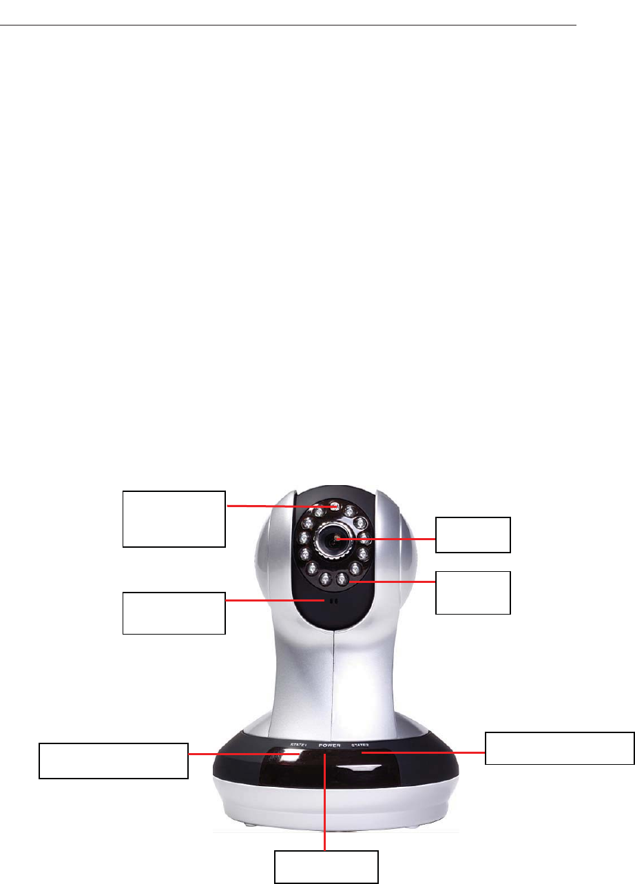
Overview of the Hardware view
IR LED
/HQ
Status Light67$7(Status Light67$7(
POWER LED
microphone
Photosensitive
sensor
6
VT - 361 user manuals
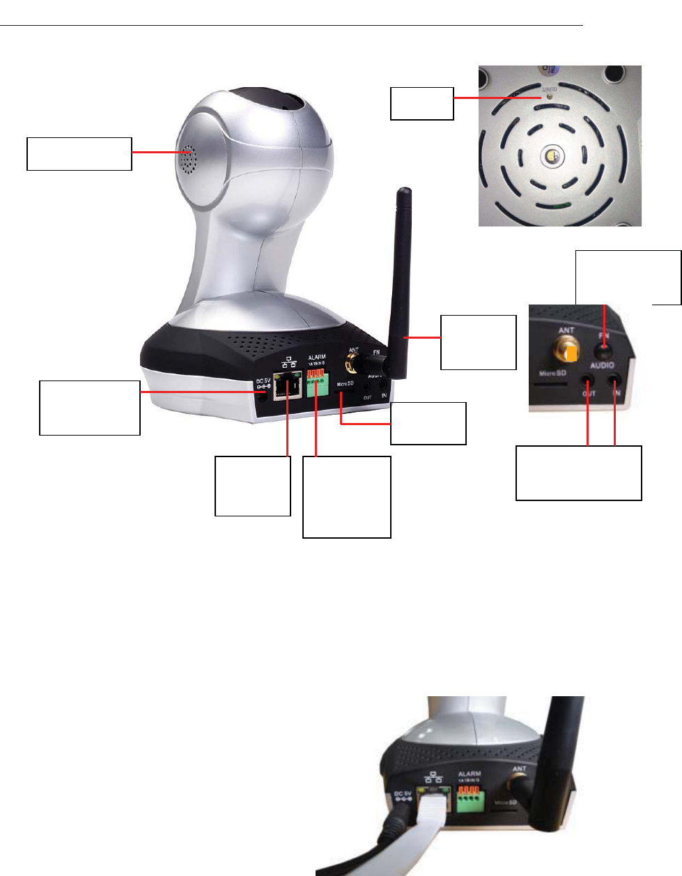
Reset
loudspeaker
FN composite
button
Note: short press the reset hole reset key is to restart function; Long press the reset button to
5 seconds, is the factory default.
Installation
Hardware Installation
Connect the network cable and power
Wired: Attach the Ethernet cord into the
Ethernet port behind the IPCAM
and the other end into the router and other
network equipment,to access network.
Wireless: The packaging comes with a w
Installed to IPCAM
ireless antenna
behind the "ANT" interface.
into the wall power outlet or Packaging wife an external power supply plugged
Line board, then the power of the DC head into the network behind the camera
DC power input interface, when the network in front of the camera
'&9 Power
Port
Ethernet
interface
External
input/output
interface
6'FDUG
:,),
Antenna
Audio input/output
interface
7
VT - 361 user manuals
POWER indicator lights up in red, indicating
that the normal supply of electricity.
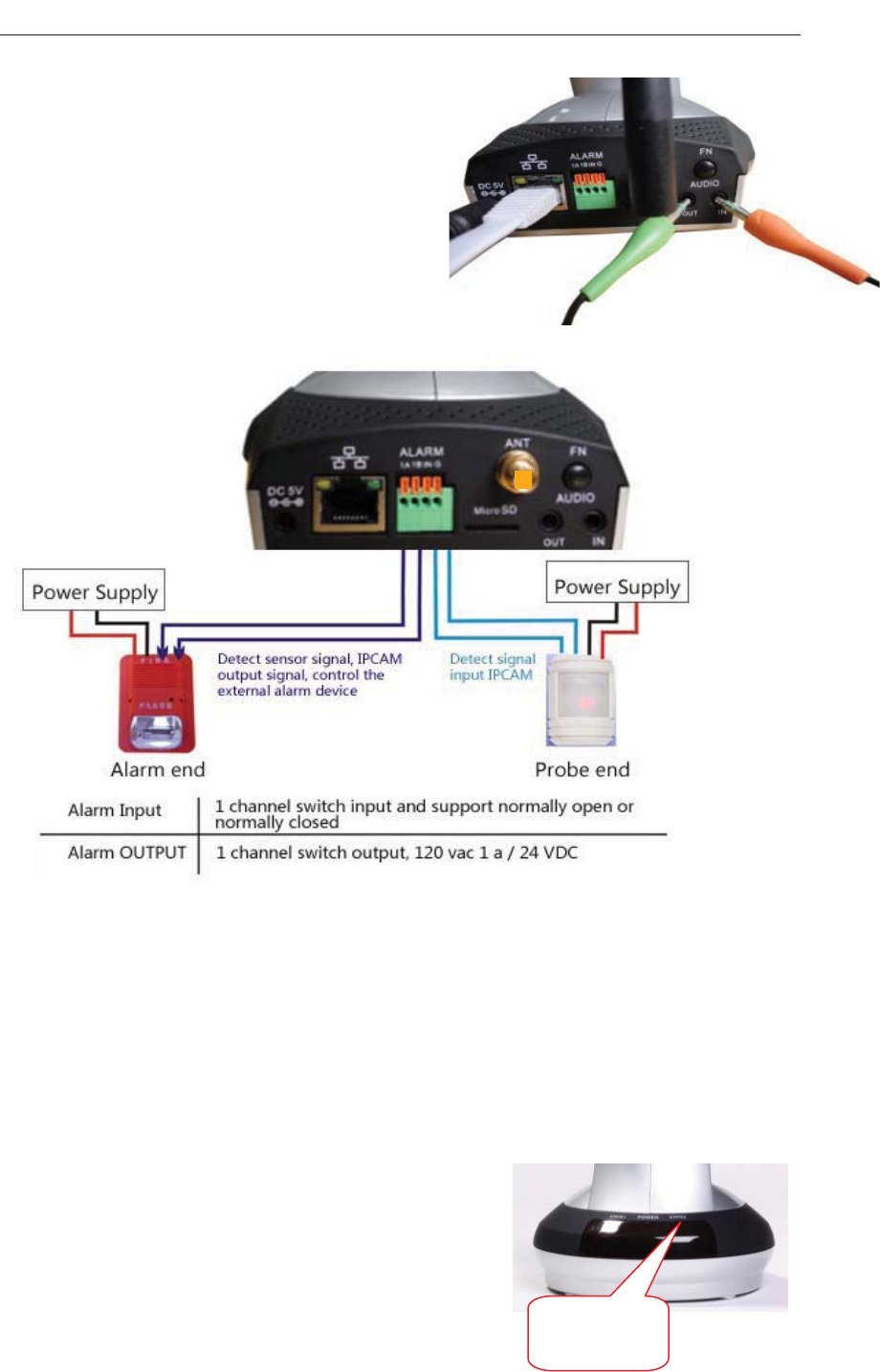
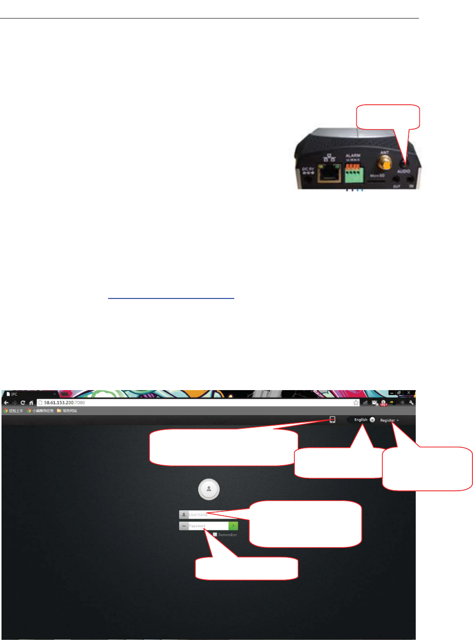
Connect an external alarm interface and an
external audio
Connect the External I / O alarm input /
output.
E
MIC and headphone connectors respec
xternal audio input / output interface:
tively mounted external 3.5 inch
ear of the machine
The first step to configure the network connection:
1.Wired internet: IPCAM connected to the power
supply and cable networks, the
front of the machine"POWER" light a long red light.
'STATE2 "lights turn red,
Wait 20 seconds, into a green light flashes (every 3
seconds flashing 7 times)
Self-test one revolution IPCMA PTZ center.
AUDIO IN AUDIO OUT inserted into the r
Camera Installation Wizard
STATE2
indicator light
8
VT - 361 user manuals
2. Wi-Fi: You can use the WI-FI Protected Setup (WPS) button for Camera to create
wireless connection. IPCAM connect electric and start, a: press the "FN" button for
green LED indicator light
g into the web interface,
. If
our router has the WPS
fter a
three seconds under the rear of the machine, then STA2
began to flicker. b: press the WPS button on the router in 60 seconds, WPS button is
FNbutton
usually in the front or side of the router. Some
routers,You may need to lo
click the button on the screen to WPS characteristics
you are not sure whether y
button, check the user manual of the router. A
successful connection , The green light of STA2 flashes (every 3 seconds flashing 7
times).
Note: The router's DHCP server function must be enabled.
The second step landing:
A: Open the browser, KWWSZZZPLSFPFRP in the address bar, enter the
following figure, the login screen, enter the ID number and password of the machin
(each IPCAM are labeled with a unique ID number need to scratch off the squeege
and password ).
e
e
odify the factory
assword, and take good care of the user name and password.
Note: After landing in order to protect your privacy, please m
p
Mobile client software to
download
languageoption The registered
accountuser
Input ID number or
registeredaccount
EnterPassword
9

VT - 361 user manuals
Note: The user can click on the login screen "Register" button to register a user to
manage multiple cameras after landing.
B.Go to the video viewing interface.
Registered users
interface
landing
UseIDlandinginterface
Clicktheplaybutton
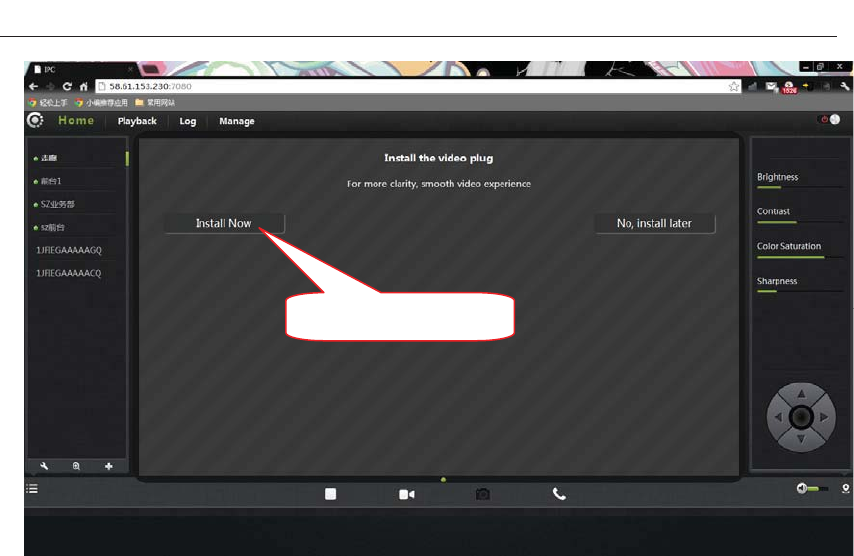
C: install plug-ins:
10
VT - 361 user manuals
Clickontheinstallplugin
outer is not connected to the Internet, users can watch video via
LAN. Running the searching tool in the CD-ROM to search the IP address of the
IPCAM. .Double-click the IP address into the login screen.
If you watch the video image blurring ,maybe the camera lens and CMOS sensor is
not a good focal ,please let the camera aim at the object away from 5 meters, slowly
to turn the lens repeatedly and slowly by hand until the image be the most clear.
Wireless Installation Considerations
IPCAM wireless cameras allow you anywhere in the wireless coverage area by using
a wireless connection to access the network. However, the wireless signal is required
to pass through the walls, ceilings and other objects in the number, thickness, and
position will limit its scope. Usually coverage changes, depending on your room or
office type of building materials and environmental RF (radio frequency)
noise. Follow these basic guidelines is the key to maximizing wireless range:
1. The Wall, ceiling between the routers and other network devices (such as
twork cameras) minimize the number - and each wall or ceiling will weaken
2-degree angle, the
Note: If the user's r
ne
adapter 3-90 feet (1-30 meters), wireless transmission range.
2. Please note that the straight-line distance between the devices. A 1.5 feet (0.5
meters) thick wall angle 45 will reach 3 feet (1 meter) thick.
11

VT - 361 user manuals
w
t
3
skeleton will weaken the wireless signal. Placing the access points, wireless
doorways. Materials and objects, such as glass, steel, metal, band insulator,
ater (fish tanks), mirrors, file cabinets, brick and concrete walls will weaken
t
4
g
5
( rated or
c as far
all thickness up to 42 feet (14 meters). To place the device into place straight
hrough the wall or ceiling (instead of angle) in order to get better reception.
. Building materials caused by the difference. The metal door or aluminum
routers and other network equipment to the signal through the drywall or open
w
he wireless signal.
. The product was placed in a position at least 3-6 feet or 1-2 meters away from
enerating the RF noise of electronic devices and appliances.
. If you are using 2.4GHz cordless phones or other radio emitting source equipment
such as microwave ovens), your wireless connection may obviously deterio
ompletely dropped. Put the 2.4GHz phone base away from the wireless device
as possible. Even if the phone is not using the dock will still transmit signals.
12
VT - 361 user manuals
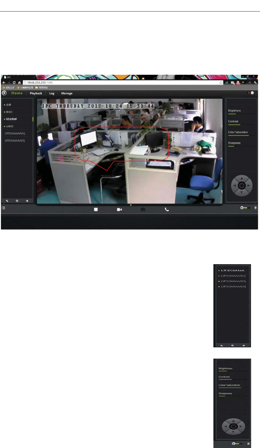
Home page
Logged in, displays the home page, click the Play button, and display real-time
video images.
on
DoubleͲclick the to
watch window, can full
screendis
video
p
la
y
One .Camera status bar:
1. Here, you can see the online status of each camera. Online status
for the following categories:
• Green means that your camera is online and ready.
• Yellow means the camera t a p word has
been changed. You need to enter
the camera again.
• Red indicates the camera is offline and not accessible remotely.
1. If the camera is offline, try the following approach:
• Check to make sure the camera's network connection is normal.
• Try restarting your network router.
• Check the camera cable connections to ensure that they are secure
connection.
• Check and confirm the camera STATE2 green light flashes
flashing (every 3 seconds flashing 7 time ).If you still cannot access
your camera, the camera is rebooted.
online, but he c mera ass
a new password in order to access
:
13
VT - 361 user manuals
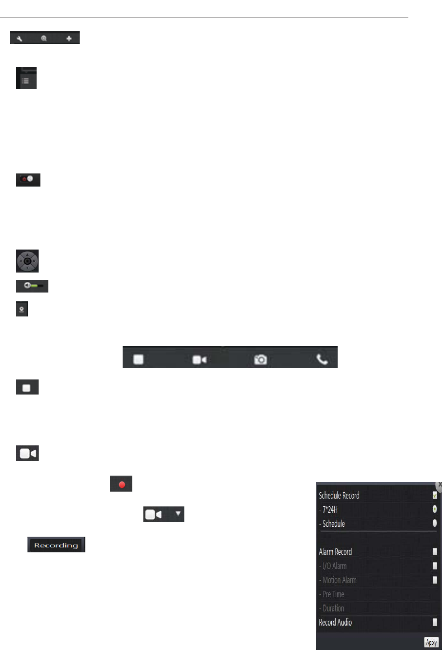
2. : Searchable the IPCAM within the local LAN, add the outer IPCAM
and manage the cameras have been added.
3. : The status bar to show and hide icons.
Two. Image settings and PTZ control bar.
1. : Exit the video interface.
2.Brightness: adjust the brightness level of the video screen.
3.Contrast: adjust the video screen contrast level.
4.Saturation: adjust the video screen color saturation level.
5. : PTZ control IPCAM up / down / left / right rotation.
6. : Control the size of the voice of the computer speakers.
7. : Status bar display and hide the icon.
Three. Interface buttons:
1. Video play / pause button: Click button on the video image playback / pause.
lick on the inverted triangle button, select playback image resolution (1280 *
720,640 * 360,320 * 180,160 * 90).
2.
C
Record button (the recorded files are stored-FLASH card): Click button on the
audio / video recording , the recording icon indicates. Click
on the inverted triangle button to enter the
mode :
The plans record: option, 7 days a week, 24 hours is not
checked
Intermittent video and regular video.
mentation of the
larm video
le investigative Alarm. Length of time
"refers to the pre-recorded pre-recorded trigger ,video before the video can be directly
input time
Alarm Recording: When checked, the imple
a
Optional I / O alarm mobi
14
VT - 361 user manuals
Seconds unit. 'Duration "refers to the reported, the police recording time can be
The recorded single frequency:
When optioned , sound recording wh
directly input time, Seconds unit.
en the alarm recording.
Click on the inverted triangle button, selectable camera picture resolution (1280 *
puter microphone / loudspeaker war, the
oice int other, we can hear each other's voices.
es.
3. Snapshot button: Click the button to capture images of the video being played.
720,640 * 360,320 * 180,160 * 90).
4. Intercom: click buttons, camera and com
two sides can v ercom, dual to each
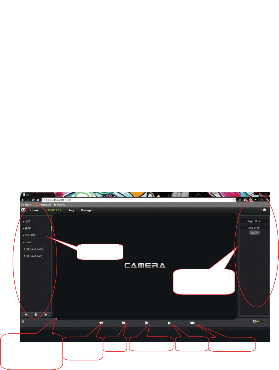
Playback
Play SD CARD-recorded video fil
Cameralist
Video file query
anddirectorylist
1. Select the camera in the camera List.
2. Queries the video files , documents and more inform
image by time.
ation on the right in the
Progress bar and
qu
videofilenumber
eries to the
fast
reverse
play/pause next
Prev FastForward
15
VT - 361 user manuals
3. After Inquire, the progress bar will be displayed by co to
file, specify the video player can be selected directly by dragging with the m
4. A video file / rewind / playback video
files
lor length query the video
ouse.
can be realized by
player image control keys to play, pause / play a video file / fast forward
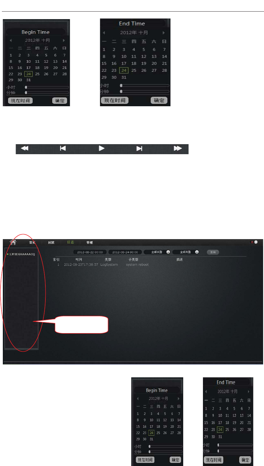
Log is a chronological log of users the IPCAM all information
Log
List.
2. Start time: i select open time.
nd time: select the end time
4. Select a state.
5. Query
1. Select the camera in the camera
3. E
16
Cameralist
VT - 361 user manuals
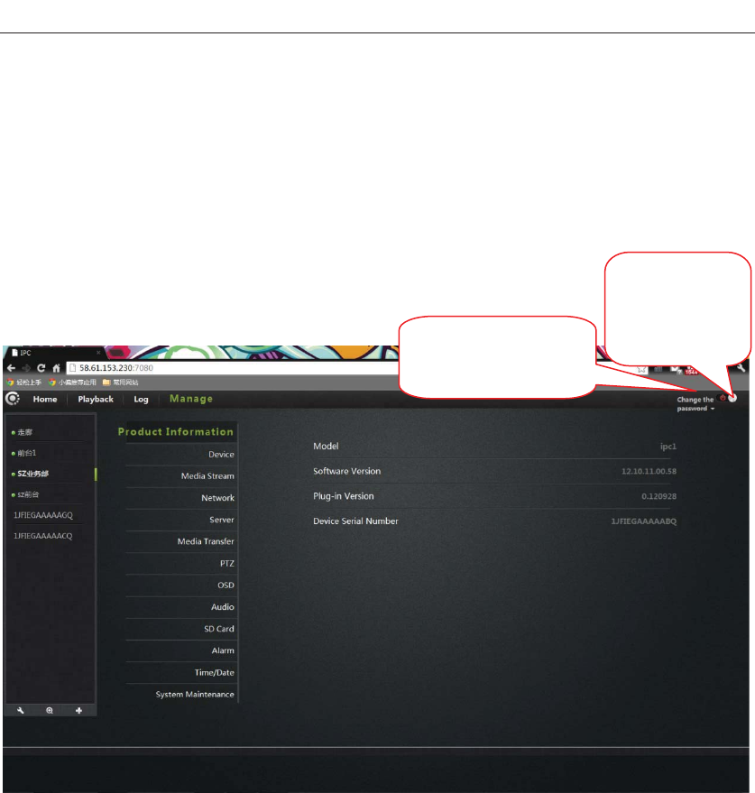
Management
This section of the configuration of the camera settings.
One. Product information:
Display the basic information of the camera.
Quit, returns
tothelanding
interface
Modify registered
users password
Model: The model of the camera.
ftware firmware version number.
Plug-in version: the camera video viewing plug-in version number.
ra.
Firmware version: the camera so
Device serial number: ID number of the came
17
VT - 361 user manuals
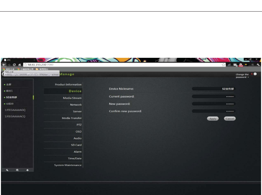
Two . Equipment
Modify camera equipment password.
Equipment nickname: the name of the camera, the user can according to their own
quirements to change the name.
assword: modify the current camera to enter the login password of the current
mera
ew Password: through here, the user can enter the current camera landed a new
ssword.
o protect your privacy, after landing modify the default password, and please take
od care of the user name and password.)
onfirm Password: Re-enter the password of the current camera modified.
lick Apply to save your changes.
re
P
ca
N
pa
(T
go
C
C
18
VT - 361 user manuals
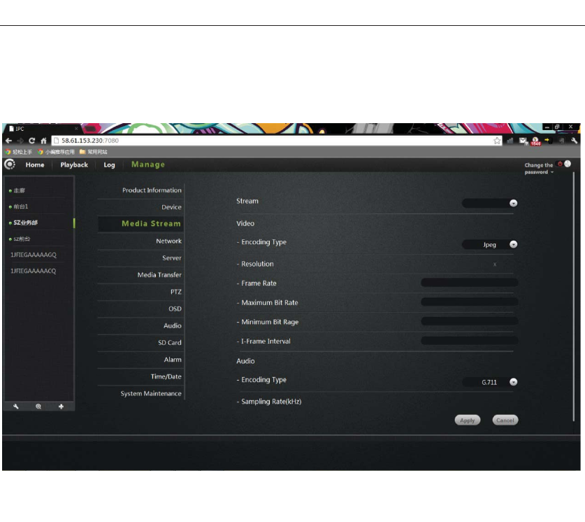
Three. Media stream:
Audio / video stream bit rate settings.
Stream: the video stream is were high (HD) / normal (normal) / half (half) / (min)
four, and their corresponding resolution of 1280*720, 640*360, 320*180,
esolution: The resolution of the image display. Select a different stream,
rresponding to the different resolution.
ramerate: the number of images per second, fps.The larger the frame rate, the more
uent image.
it rate: bps unit. Bit rate, image display more clear, but the highest occupied
twork resources. The user can set a maximum and minimum values.
frame interval: send each keyframe interval.
udio:
ncoding types: audio encoding, G.711, G.726, AMR, AAC four encoding
Sampling rate: refers to the frequency of the audio samples.
r changes.
160*90.Different stream, Framerate / bitrate / I frame interval set.
Image:
R
co
F
fl
B
ne
I
A
E
Click Apply to save you
19
VT - 361 user manuals
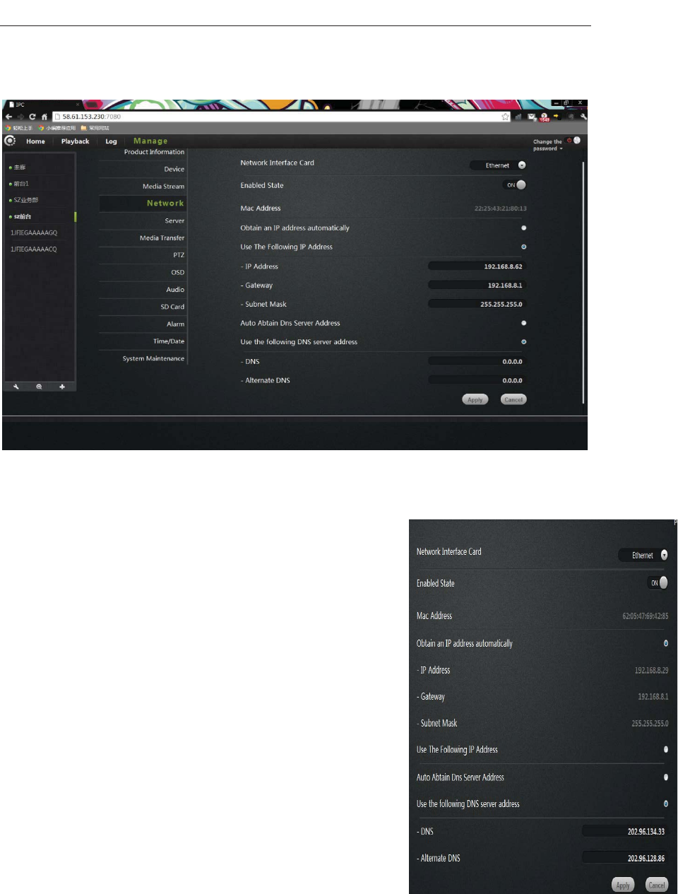
Four. Network
NIC: Ethernet (wired) and wireless networks.
1. Ethernet:
work.
automatically get connected to the router and it
ck the user manual
location
One IP address / gateway / subnet mask to the camera.
Dns server address automatically exercised: Check, camera
Automatically get to be automatically assigned to the router connected to it
Its DNS information.
Following dns server addresses: user
Manually assign DNS to the camera
Effective when connected to a wired net
Startup Status: Displays the current Ethernet enable /
disable.
Mac address: Displays the current Ethernet Mac address.
Automatically obtain an IP address (cameras default):
select camera
Machine
is automatically assigned to
IP address / gateway / subnet mask information.
Use the following IP address: Che
al
20
VT - 361 user manuals
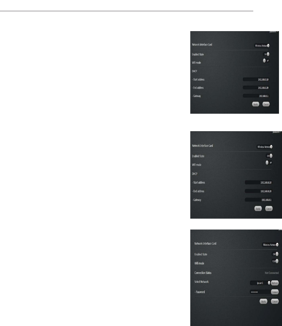
2. Wireless Network:
NIC choose a wireless network.
Startup Status: Displays the current wireless network, enable /
disable.
Wireless mode: hot / terminal
A. Hot spot: as the default search equipment, network cameras,
wireless hot mode, wireless devices through wireless searchˈ
Point-to-point connection to the camera.
DHCP: Dynamic Host Configuration Protocol for wireless hotspots, starting address
to the end the address and gateway.
B. Terminal: As search equipment.
Connection Status: Displays the status of the wireless
network.
Select Network: Wireless will automatically search for the
cameras surrounding the wireless network terminal in the
drop-down list, select the wireless network terminal.
network
equipment.
Click the connect button to connect the selected wireless
o save your changes.
Mac address: displays the current wireless network Mac
t):
teway / subnet mask information.
era.
eck
lly get to be automatically assigned to the router connected to it
ur changes.
Password: Enter the password for the wireless
Click Apply t
address.
Automatically obtain an IP address (cameras defaul
select camera
Machine automatically get connected to the router and it is
automatically assigned to
IP address / ga
Use the following IP address: Check the user manual
allocation
One IP address / gateway / subnet mask to the cam
Dns server address automatically exercised: After ch
Automatica
ed, camera
its DNS information.
Following dns server addresses: After checked, user
Manually assign DNS to the camera.
Click Apply to save yo
21
VT - 361 user manuals
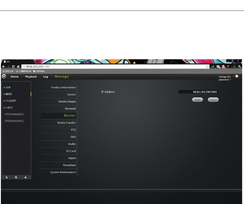
Five. Servers
IP address: the camera is connected to the server's IP ad
Click Set to
dress.
save your changes.
22
VT - 361 user manuals
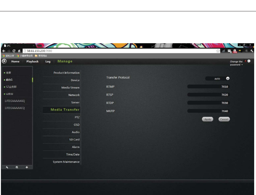
Six. Media transfer:
Transfer Protocol: drop-down list have RTMP, RTSP, RTDP, MUTP, four transport
protocol, select AUTO (the default protocol RTDP).
RTMP: port 7010, do not install the plug when viewing images with this agreement.
ing media
LC Universal Player) video.
TDP / MUTP: ports 7030/7040, private P2P video streaming protocol.
Click Apply to save your changes.
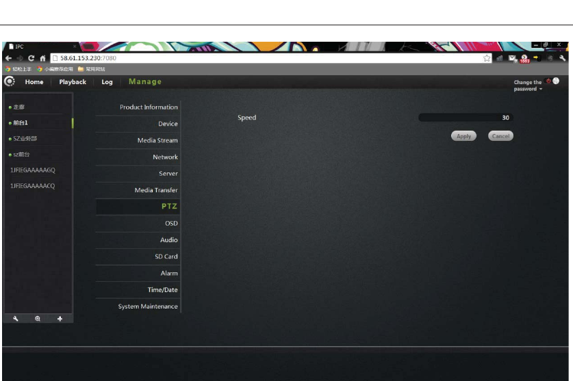
Seven. PTZ
PTZ rotation parameter settings.
RTSP: port is 7020, this agreement play equipment suitable for stream
player (such as QuickTime and V
R
23
VT - 361 user manuals
Speed: PTZ speed parameter settings, the greater the value, the PTZ faster.
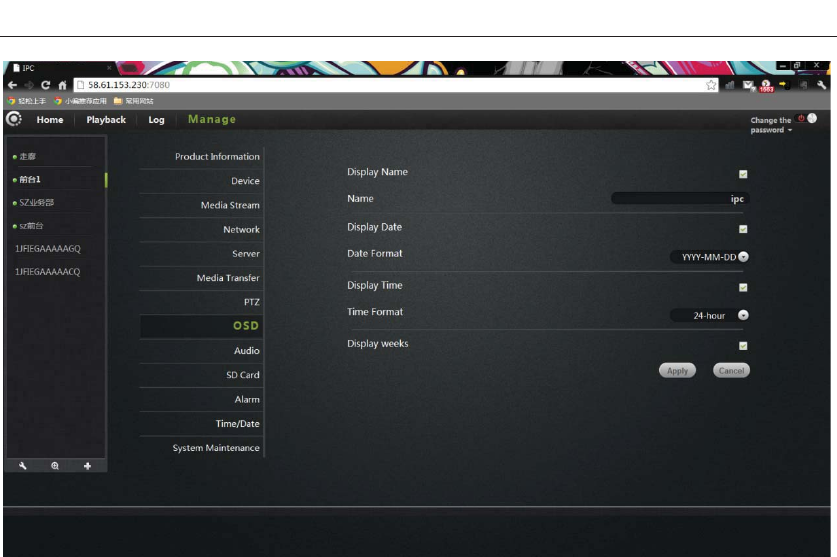
ight. OSD:
Image screen display menu settings.
Click Apply to save your changes
E
24
VT - 361 user manuals
Display Name: After checked , will display the name of the camera in the top left
corner of the screen.
een displays the name of the camera.
Display date : After checked , will display the date of the camera.
ate format: User can select year / month / day or month / day / year both date
formats.
how time: After checked , will display the time of the camera.
ime format: user can select 24-hour or 12-hour system.
eek: Check the upper left corner of the screen displays the day of the week.
lick Apply to save your changes
Name: The user can modify the scr
D
S
T
Display w
C
25
VT - 361 user manuals
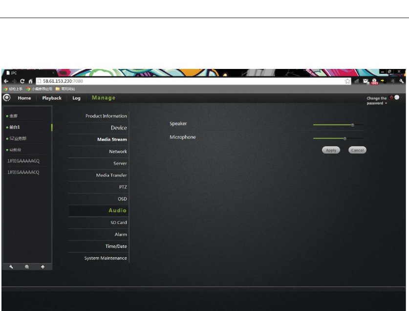
Nine
ˊ
Audio:
Speaker: Set the camera the size of the sound from the speakers, use the mouse to
aker
icrophone: Set the sensitivity of the camera microphone, use the mouse to drag the
receiving sound
gly,
r noise of the monitored environment.
lick Apply to save your changes.
drag the slide bar, the greater the value, the greater the sound from the spe
M
slide bar to set, the greater the value, the more sensitive microphone
external environment, the greater voice of the monitored computer end, accordin
the greate
C
26
VT - 361 user manuals
Ten
ˊ
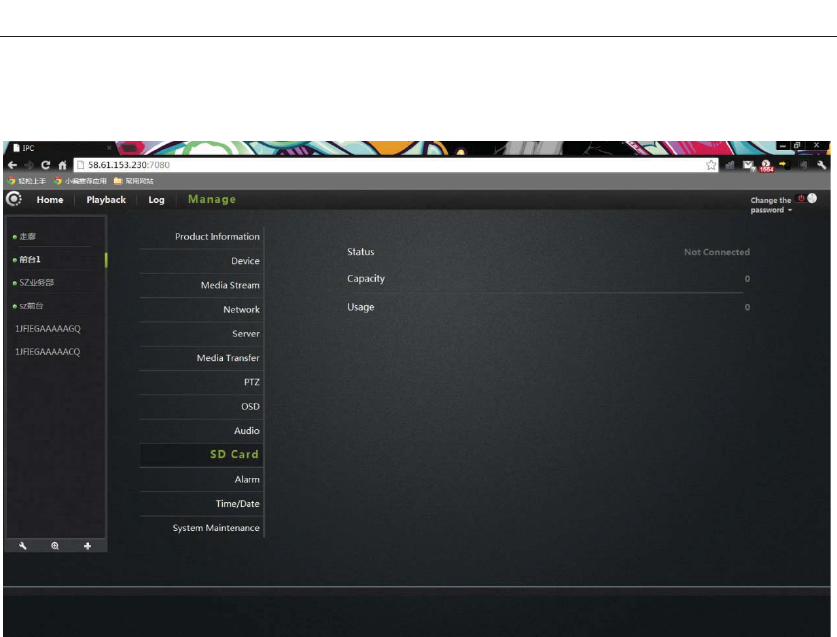
SD card:
Display the status of the camera SD card.
been Status: Displays the current SD card plugged into the camera and whether it has
read to the camera.
Capacity: Show the total size of the plug into the camera's SD card.
Usage: displays the current plug into the SD card in the camera has been used in the
situation.
Click Apply to save your changes.
27
VT - 361 user manuals
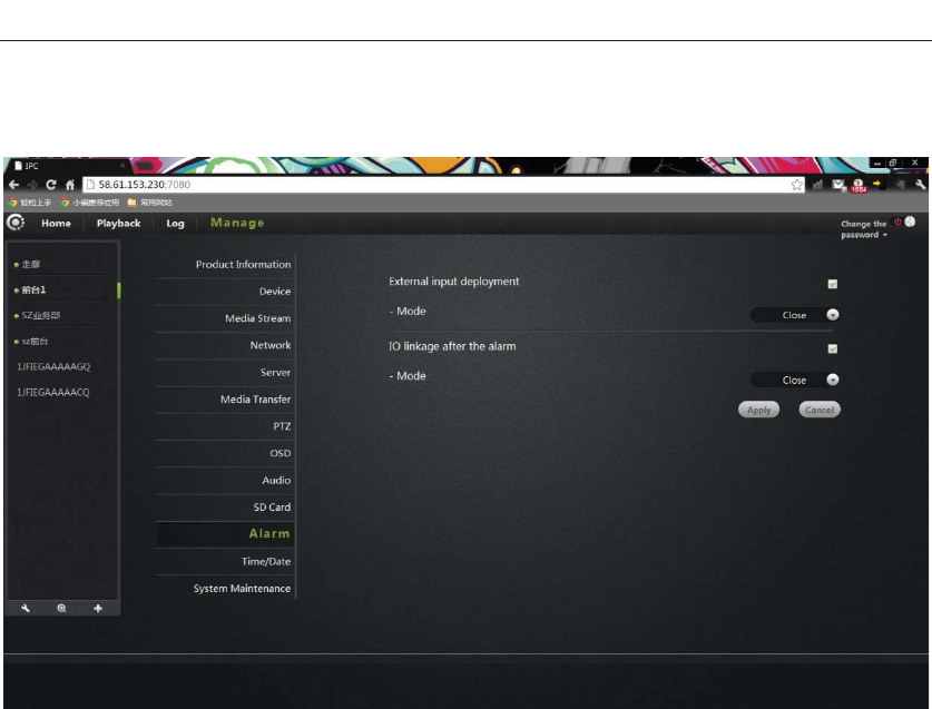
Eleven. Alarm:
External input arming: trigger signal input, an external alarm sensor probe (such as
smoke alarms probe).Checked mode depending on the type of external alarm probe
m trigger signal output, external alarm equipment (such as
e output alarm
external alarm devices.
equipment to select normally closed or normally open.
IO linkage: the alar
speaker equipment). Checked, the machine triggered the alarm linkag
signal to trigger external alarm, normally closed or normally open mode depending on
the type of
Click Apply to save your changes.
28
VT - 361 user manuals
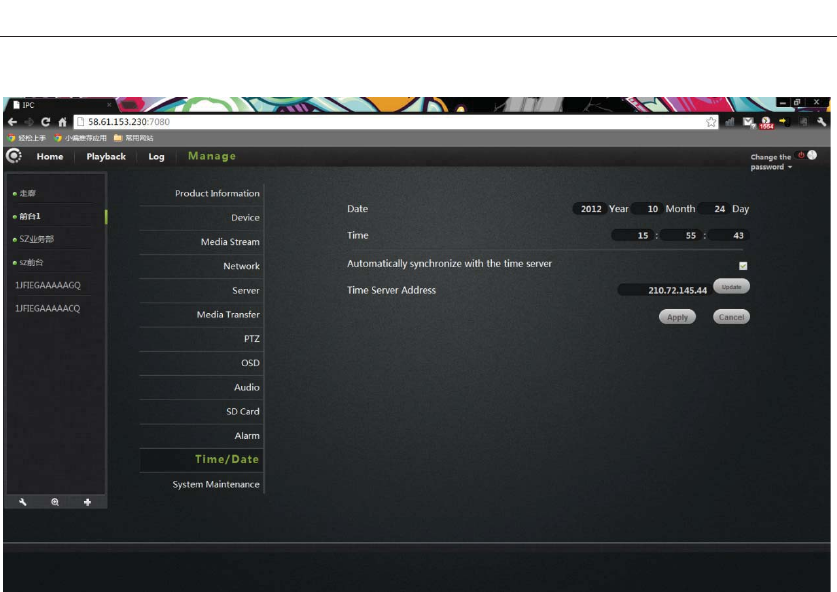
Twelve.Date/Time
Date: the date of the camera can be manually modified.
Time: time of the camera can be manually modified.
Automatically synchronized with the time server: after checked , the camera time
is automatically synchronized with the server time.
Time server address: the address of the time server.
Click Apply to save your changes.
29
VT - 361 user manuals
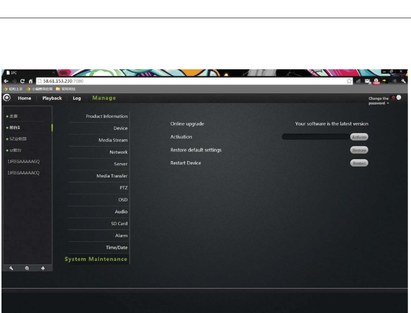
Thirteen .System maintenance:
Online upgrade: If you have the latest software will prompt <update> click update,
ain risk, software upgrade and
e up dead.
the restore button, the camera will be restored to
e factory default settings, the user will cancel the camera settings made.
Restart the device: click on the reset button to restart the camera.
Click Apply to save your changes.
the camera will upgrade the software online.
Note: Software upgrade on the camera there is a cert
cannot cut off the network, or they can put the machin
Restore the default settings: click
th
30

VT - 361 user manuals
Troubleshooting
This chapter provides solutions to problems that may arise in the IP CAMERA
install and running.
If you encounter problems, please read the following description. (The following
example is based on Windows ® Vista ™ and XP Description If you are using a
different operating system, your computer screen and following a similar example.)
1. What is remote access? How do I enable it?
Through remote access, you can use a web browser from any PC connected to the
Internet to access the camera. So even if you are not at home, you can watch the
camera images, and manage the camera settings.
To enable remote access, you can simply follow the Quick Installation Wizard.
If you are not connected on the camera, make sure the following items:
ter by unplugging the power and then plug it in
again the way
After the completion of the inspection of the above, you can re-landing.
2. Why photo camera's network connection unreliable?
The network cable may be a problem. Make sure the cable is working, PING
network known address of the device. If the cable connection is correct and your
network connection is working, you should receive a similar (bytes = 32 time = 2 ms)
reply.
Another possibility is that the network camera network devices such as hubs or
switches, there is a problem. Make sure that the power for all devices are connected
and working properly.
Why Network Camera work locally, but the remote does not work?
This may be caused by the firewall protection, and your system administrator to
check network firewall. The firewall may need to make some configuration changes,
in order from your local LAN, external access to the network camera. For more
....The green LED camera on SETATE2 green light flashes (every three seconds
shiny 5 times).
....Network connection is working properly
... Router's LAN & WAN connection is working properly.
... The router has enabled UPnP.
... The router can get a public network IP.
... The router has been upgraded to the latest firmware version.
... You have tried to restart the rou
3.
31

VT - 361 user manuals
detailed information, please refer to the relevant sections of the cameras installed in
the router backend.
Ensure that the network camera does not conflict with any Web server running on
gs
external access from your local LAN network cameras.
4. Why the image on some of the vertical white line?
e
the form of an image presented to
t
.
urred.
cus, the
ted until the image is most clear.
ve the image quality?
colors.16 or 256 colors
facts, it seems the quality will be poor.
igured correctly. Configuration through
arameters to
r
Explorer to see the
lso
g.
owser, in order to watch the video sent by the network camera.
your network.
The default router setting might be the problem. Make sure that the router settin
configured to allow
There may be a CMOS sensor due to exposure to light (such as direct exposure to
sunlight or a halogen light) and overload result. The CMOS sensor is located in th
rear of the lens, its role is the measurement light signal and converts it to a digital
format so that the computer will digital format in
the user. CMOS sensor is a long time in the bright light , the network camera canno
be immediately transferred to a dark area, so as not to damage the CMOS sensor.
5. The camera blurred image, how to solve?
If the network camera work where light is dim, the video image may become bl
Another possibility is that the camera lens and CMOS sensor not good fo
camera aligned 5 meters away from the object, turn the lens slowly by hand
repeatedly adjus
6. The image quality is poor, how to impro
Determine your computer's display properties set at least six
makes the image appear jitter arti
Network Camera image display is not conf
the Web Management Web video interface, you can adjust the p
improve the image quality, these parameters include: brightness, contrast, and colo
saturation.
7. Why no images on the Web browser?
The ActiveX might not enabled. If you are through Internet
image, make sure to enable ActiveX in the Internet Options menu. You may a
need to modify the browser's security settings to allow installation of ActiveX plu
If you are using Internet Explorer version is less than 7.0, you need to upgrade to a
Web br
8. Troubleshooting, LED status indication:
Indicator Indicator flashing Status
frequency
POWER (red light) Long bright normal Power supply
STATE1 (red light)
32

VT - 361 user manuals
flash 2 times every 3 SD card connected
seconds
STATE1 (green light)
flash 2 times every 3 Did
seconds
not get to the IP address
STATE2 (red light)
flash 2 times every 3
seconds
Connected on the router, but
not connected to external
networks
flash 5 times every 3 Wired is connected to external
seconds networks, and can be accessed
remotely
S
the
outside network, remote access
TATE2 (green light)
flash 6 times every 3
seconds
Wireless connection on
33

VT - 361 user manuals
Wireless Infrastructure
IP CAMERA wireless products are based on industry standards for your home,
business or public access wireless network to provide a simple and compatible
high-speed wireless connect str ,
here secure access to the data you need.
y th reedom of the wireless network.
Wireless LAN (WLAN) is a unit of the computer network by a wireless signal
instead of wires to transmit N e
and office environments, as well as public places such as airports, coffee shops and
universities. WLAN technology in innovative ways to help the character work , and
ectiv her
better mobility provides mo ience for many
In many environments, the mobile network equipment needs to be connected to a
conventional Ethernet LAN , p
connection via a wired LAN. The wireless router is u
What is wireless?
Wireless or WiFi technology is not using a cable to connect your computer to a
network. WiFi uses radio frequency to connect wirelessly, so you can be free to
connect computers anywhere in your home or office network.
ireless equipment?
IPC1 is the world's leading real smartphone remote monitoring network camera
products, can get the smoothly and clearly video. And access the real P2P
technology. IPC1 products at reasonable prices, and excellent performance.
does the wireless network work?
Similar with wireless phone when the wireless network work , through radio
signals to transmit data from point A to point B. However, a wireless
network have some restrictions on how you access the network . You must
be the coverage of the wireless network, in order to connect to your
computer. The wireless network is divided into two different types of
wireless local area network (WLAN) and wireless personal area network
(WPAN).
cal area network (WLAN)
ion. The IP CAMERA ictly follow the IEEE standard
wireless products allows you anytime, anyw
You will be able to enjo e f
and receive data. WLA is more and more used in hom
communicate more eff ely. No cabling and ot
re conven
fixed infrastructure, as well as
users.
, in order to use servers rinters or an Internet
sed to provide such a
connection device.
Why buy IPC1 w
How
Wireless lo
34

VT - 361 user manuals
In wireless local area network, the access point (AP) as a computer to access
the network device. The access point has a small antenna, whether through
radio signals to transmit data. Indoor access point shown in the drawing, the
signal can reach a distance of 300 feet. In outdoor access point signal
years, almost
me are as in the office .everything will be in your hands
r office from home.
•
Wh
wireless technology is being extended
becom
wireles
usually called "hot spots".
an be in distant places such as: airports,
hot
The to
wo
the ss for
the
Prompt
distance up to 30 miles .Can be used such as a factory floor, industrial areas,
college and high school campuses, airports, golf courses, as well as many
outdoor occasions.
Which kind person are suitable for wireless network?
Increasingly popular wireless network technology in recent
everyone is using it, it can provide wireless solutions for the home, office
and business, D-Link.
Home
• provide for everyone at home broadband access.
• browse the web, view email, instant messaging, etc.
• No cable connection in the room around
• Simple and easy to operate
SOHO (Small Office and Home Office)
• When you at ho
• Remotely access you
• Multiple computers to share an Internet connection and a printer
Does not require a dedicated office space
ere to use the wireless network ?
Not just confined to the home and office,
to every corner. People like the freedom of mobility, wireless networks are
ing increasingly popular, more and more public places began offering
s access to attract people. The wireless connection in public places is
Use a wireless card in your laptop, you c
els, cafes, libraries, restaurants and conference center with wireless network.
wireless network is easy to install, if you first installed, you will need
rk hard to understand where to start. This is why we want to provide some of
installation steps and tips to help you complete the installation proce
wireless network.
35

VT- 361 user manuals
Wh
Pos
Ver , in
ord
poi
hom lding, you need to install the repeater signal expanding
Eli
Ho s
far ter / access point. This will greatly reduce the
electrical interference caused by the work at the same frequency.
Sa
Pre our wireless
network. Open the router' rity features to protect your wireless
net set the properties detailed
in
Wir
T r data
f
IPC1 provides the following security types:
Wg
the RC4 encryption algorithm. WEP for data encryption via your wireless network
to provide security, so that it can protect the security of transmission from one
wireless device to another
To access the WEP network, you must know the key. The key is the string you create.
U ust specify the level of encryption. The type of encryption
en you install a wireless network, please note the following:
t your router or access point on the center place of the network.
ify that your router / access point on the center position of the network
er to get the best results. Try to place the router / access point to the highest
nt in the room, so that the signal can be distributed to your room. If your
e is a two-story bui
coverage.
minate interference
usehold appliances, such as cordless phones, microwaves, and televisions a
as possible from the rou
fe
vent your next door neighbors or intruders connect to y
s WPA or WEP secu
work. Please refer to the product manual to
formation.
eless Security
his section describes the different levels of security you can use to protect you
rom intrusion. .
• WPA-PSK (pre-shared password)
• WEP (Wired Equivalent Privacy)
What is WEP?
EP is Wired Equivalent Privacy. It is based on the IEEE 802.11 standard, usin
sing WEP, you m
36

VT - 361 user manuals
d .Key input HEX
( Code -
alphanumeric characters) format string definition. ASCII format allows you to enter
t erted
i
What is WPA?
WPA, or Wi-Fi Protected Access, is a Wi-Fi standard, designed to improve the
s Wired Equivalent Privacy).
H
Im
(T adding
in -checking feature, ensures that the keys have not been tampered
wd
(
U,
g in WEP.WEP-based computer hardware MAC address to
t access to the wireless network is relatively easy be listened and stealed.
n a more secure public key encryption system to ensure that only
through authorized network users can access the network.
WPA-PSK/WPA2-PSK uses a passphrase or key to authenticate your wireless
is an alphanumeric password, 8-63 characters long. The
password can include symbols (!?* & _) And spaces. This key must be entered on
your wireless router or access point the same key.
Complete the quick installation the IP CAMERA guide installation, you can use the
ork through a router, so assigned to the IP address of the network
see the camera, configure the router to
all be viewed on the network.
Specifications
etermines the key length.128-bit encryption key is longer than 64
16 hex -0-9, AF) or ASCII (American Standard Information Interchange
he easy-to-remember string. ASCII string used on the network transmitted conv
nto HEX. Righteousness four keys can be given. You can easily change the key.
ecurity features of WEP (
as two major improvements than WEP:
prove data encryption through the Temporal Key Integrity Protocol
KIP).TKIP scrambles the keys using a hashing algorithm and, by
tegrity
ith.WPA2 is based on 802.11i, using the Advanced Encryption Standar
AES) instead of TKIP.
ser authentication through the Extensible Authentication Protocol (EAP)
usually missin
restric
EAP builts o
connection. The key
IP address has been assigned the camera. A local IP address for your PC and one or
more shared netw
camera. At this time, your local network can
ow the camera from a remote viewing can
Specification IPC1
Sensor 1/4 "color CMOS sensor
Ima
)
ge sensor
Display
Resolution 1280 * 720 pixels (1,000,000 pixels
37

VT - 361 user manuals
there is a camera f: 3.6mm, F: 2.4
Minimum
illumination 0.5Lux
Perspective 65 degrees
Input / Output Built-in MIC and SPEKER, two-way voice intercom
A
frequency Compression G.711/G.726/AAC/ADPCM
udio Audio
Video
compression
mode MJPEG/MPEG4/H.264
Lighting
frequency 50Hz, 60Hz
Image frame rate 1-30fps
Image resolution 1280 * 720,640 * 360, 384 * 216,256 * 144
White balance,
backlight
compensation Automatic Query
V
rs
ideos
Night Vision 12 IR LED, IR distance: 10 mete
Ethernet A 10/100Mbps RJ-45 interface
Support
Agreement
TCP / IP, UDP / IP, HTTP, SMTP, FTP, D
UPNP , RTSP And RTMP, MUTP
HCP, DDNS,
Wireless
standards WIFI (IEEE802.11b)
Ne
ress
twork
Support IP
addresses Static IP address and dynamic IP add
Alarm detection Motion Detection
Alarm
notification
Support E-mail, FTP, SMS alarm alarm notification
methods (requires server support)
Alarm
External alarm External alarm input / output
Memory card Micro SD card. (Supports up to 32GB)
Power
DC 5V/2.0A and POE power supply (optional), po
consumption <8 watts
wer
Audio input /
output interface An audio output jack and an audio input socket
Button A reset button, a function button
Wireless
face 1 WIFI external antenna interface inter
Hardware
interface
External alarm I
/ O External alarm I / O port
PTZ rotation
Horizontal: 320 ° & Vertical: 120 ° angleother
LED indication Power / network signal / function indicator
Environment
38
Operating 0 ° ~ 55 ° C (32 ° F ~ 131 ° F)

VT - 361 user manuals
Temperature
Operating
humidity 10% ~ 80% RH (non-condensing)
Storage
temperature -10 ° C ~ 60 ° (14 ° F ~ 140 ° F)
Dimens
(L*W*H)
ions
112 (L) *114 (W) *157mm (H)Specificatio
400g (Containing rack)
n
Weight
Central
processor 2.0GHz .0GHz)or above (recommended 3
RAM 256MB or more (Recommended 1.0GB)
Graphics Card 64MB or more
Operating
system
Microsoft Windows 2000 ta, Windows7, Mac OS, /XP, Vis
Linux
Computer
Re
IE6 or later / Firefox / Google browser or other
standards-compatible browser
quirements
Browser
Identification certification CE, FCC,ROHS
39

1
FCCStatement
˖
1.ThisdevicecomplieswithPart15oftheFCCRules.Operationissubjecttothe
followingtwoconditions:
(1)Thisdevicemaynotcauseharmfulinterference.
and(2)Thisdevicemustacceptanyinterferencereceived,includinginterferencethat
maycauseundesiredoperation.
2.Changesormodificationsnotexpresslyapprovedbythepartyresponsiblefor
compliancecouldvoidtheuser'sauthoritytooperatetheequipment.
NOTE:
ThisequipmenthasbeentestedandfoundtocomplywiththelimitsforaClassB
digitaldevice,pursuanttoPart15oftheFCCRules.Theselimitsaredesignedto
providereasonableprotectionagainstharmfulinterferenceinaresidential
installation.
Thisequipmentgeneratesusesandcanradiateradiofrequencyenergyand,ifnot
installedandusedinaccordancewiththeinstructions,maycauseharmful
interferencetoradiocommunications.However,thereisnoguaranteethat
interferencewillnotoccurinaparticularinstallation.Ifthisequipmentdoescause
harmfulinterferencetoradioortelevisionreception,whichcanbedeterminedby
turningtheequipmentoffandon,theuserisencouragedtotrytocorrectthe
interferencebyoneormoreofthefollowingmeasures:
Reorientorrelocatethereceivingantenna.
Increasetheseparationbetweentheequipmentandreceiver.
Connecttheequipmentintoanoutletonacircuitdifferentfromthattowhichthe
receiverisconnected.
Consultthedealeroranexperiencedradio/TVtechnicianforhelp.
The distance between user and products should be no less than 20cm