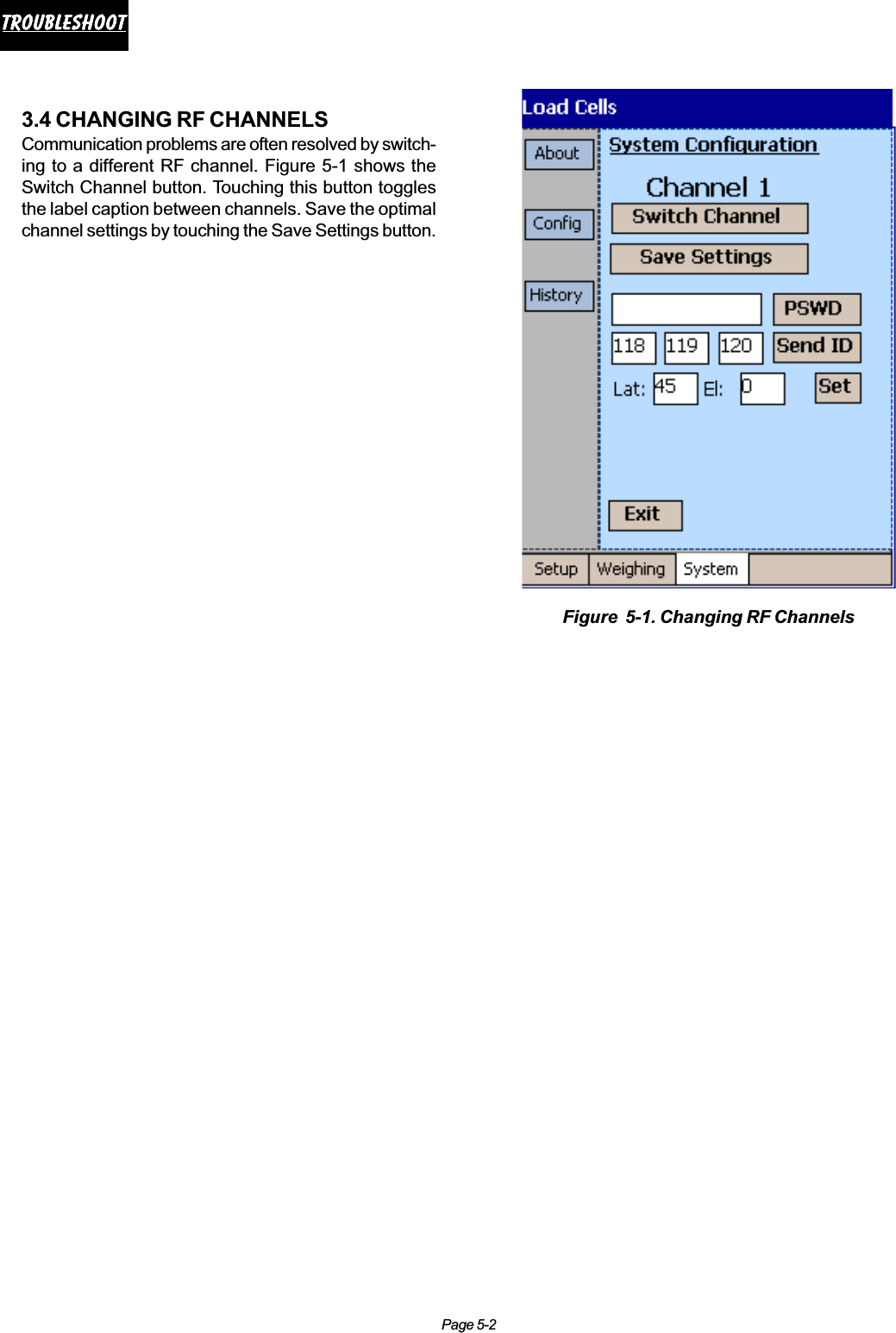
Vishay Tedea Huntleigh JETWEIGH-W-M Point Wireless Aircraft Weighing System User Manual

Vishay Tedea-Huntleigh International Ltd. Point Wireless Aircraft Weighing System

User Manual

Important Notices: (1). This equipment has been tested and found to comply with the limits for a Class B digital device, pursuant to part 15 of the FCC Rules. These limits are designed to provide reasonable protection against harmful interference in a residential installation. This equipment generates, uses and can radiate radio frequency energy and, if not installed and used in accordance with the instructions, may cause harmful interference to radio communications. However, there is no guarantee that interference will not occur in a particular installation. If this equipment does cause harmful interference to radio or television reception, which can be determined by turning the equipment off and on, the user is encouraged to try to correct the interference by one or more of the following measures:-Reorient or relocate the receiving antenna. -Increase the separation between the equipment and receiver. -Connect the equipment into an outlet on a circuit different from that to which the receiver is connected. -Consult the dealer or an experienced radio/TV technician for help. (2). Changes or modifications to this equipment not expressly approved by the party responsible for compliance (Vishay Israel Ltd.) could void the user’s authority to operate the equipment. (3). The antenna used for the load cell transmitter must be installed to normally provide minimum separation distance of at least 20 cm from all persons and must not be co-located or operating in conjunction with any other antenna or transmitter. The handheld terminal is portable but restricted to occupational/controlled use only. It is not authorized for consumer or general population use. Personnel using the terminal must be trained regarding RF exposure and its control.Vishay makes no representation or warranties of any kind whatsoever with respect to the contents hereof and specifically disclaims any implied warranties or merchantability or fitness for any particular purpose. Vishay shall not be held liable for errors contained herein or for incidental or consequential damages in connection with the furnishing, performance, or use of this publication or its contents. Vishay reserves the right to revise this manual at any time and to make changes in the contents hereof without obligation to notify any person of such revision or changes. Cover photo courtesy of the USAF
icontentscontentscontentscontentscontentsTable of ContentsSection I - General Information1.1 INTRODUCTION .................................................................................................................... 1-11.2 SYSTEM COMPONENT DESCRIPTIONS ............................................................................. 1-21.2.1 Wireless  Handheld Terminal .......................................................................................................................... 1-21.2.2 Wireless Load Cells ......................................................................................................................................... 1-21.2.3 Load Cell Adapters .......................................................................................................................................... 1-21.2.4 Thermal Printer ................................................................................................................................................ 1-2Section II - Pre-Operation2.1 PRE-OPERATIONAL PROCEDURES.................................................................................... 2-12.1.1 Load Cell Jack Point Configuration ................................................................................................................ 2-12.1.2 Preparation for Aircraft Weighing .................................................................................................................. 2-12.2 TERMINAL SETUP ................................................................................................................ 2-22.2.1 Setup Screen Options ..................................................................................................................................... 2-22.2.2 Main .................................................................................................................................................................. 2-22.2.3 Gravity Factor Compensation ......................................................................................................................... 2-32.2.4 A/C .................................................................................................................................................................... 2-32.2.5 Channel ............................................................................................................................................................ 2-42.2.6 Changing Channel ID and Location ................................................................................................................ 2-4Section III - Operation3.1 LOAD CELL POWER UP ....................................................................................................... 3-13.2 TERMINAL POWER UP ......................................................................................................... 3-13.3 AIRCRAFT WEIGHING CYCLE ............................................................................................. 3-13.3.1 Zeroing ............................................................................................................................................................. 3-13.3.2 Lifting ................................................................................................................................................................ 3-33.3.4 Removing ......................................................................................................................................................... 3-53.3.5 Rezeroing ......................................................................................................................................................... 3-53.3.6 Weighment Report .......................................................................................................................................... 3-5Section IV - Weighing History4.1 RECALL A RECORD FROM THE HISTORY FILE ................................................................. 4-14.2 RECALLING AIRCRAFT FROM THE LIBRARY .................................................................... 4-14.3 AIRCRAFT NOT RECORDED IN THE LIBRARY ................................................................... 4-1Section V - Troubleshooting5.1 TROUBLESHOOTING OVERVIEW ....................................................................................... 5-15.2 LED STATUS INDICATORS ................................................................................................... 5-15.3 TYPICAL PROBLEMS AND SOLUTIONS ............................................................................. 5-15.4 CHANGING RF CHANNELS .................................................................................................. 5-2
Page 1-1IntroductionIntroductionIntroductionIntroductionIntroductionSection I - General Information1.1 INTRODUCTIONThis manual provides information on the operation ofJetWeigh-W™ Wireless Aircraft Weighing System se-ries aircraft electronic weighing kits manufactured byVishay SI Technologies.  JetWeigh-W™ Wireless Air-craft Weighing Systems (Figure 1-1) integrate state-of-the-art wireless communication, digital weight pro-cessing, and high-accuracy hermetically sealed loadcells. Combined technologies from Vishay RevereTransducers and Vishay RFWaves results in an accu-rate, high-reliability, robust, and easy to use WirelessAircraft Weighing System.JetWeigh-W kits are designed primarily for the weigh-ing of aircraft and aerospace vehicles, but can beused for other precision weighing applications, as wellas for the calibration of force generating machines.The kits have been calibrated using dead weight ma-chines.  These machines are maintained to better than±0.001% with respect to the nominal weight value.  Thedegree of uncertainty for all of the individual weightsis approximately ±0.005% with respect to true values.All readings are corrected to standard gravity factor“g” as required by MlL-W-7327C.High capacity JetWeigh-W kits with load cell capaci-ties of 200,000 lb are calibrated on Vishay Revere’shigh capacity precision hydraulic transfer standard.On completion of this calibration, the JetWeigh data isverified on the dead weight machine up to the 100,000-lb point.  Maximum acceptable deviation between thetransfer standard and dead weight data is ±0.05%.Both the dead weight machine and the transfer stan-dard are secondary standards and are directly trace-able to NIST.It is recommended that the kit be returned to the fac-tory for routine calibration every twelve (12) months orsooner if trouble is observed or erroneous readingsare suspected.The load imposed on a load sensor produces anoutput signal directly proportional to the load applied.The signal is transmitted through a wireless channelto the JetWeigh handheld terminal where the mea-surement is processed. Analog load sensor signalsare processed digitally to remove linearity errors,latitude and altitude effects. Presentation in poundsor kilograms is selectable by the operator.  Anintegral printer provides a permanent record of allpertinent weighment information including anydeviations that are accepted by the operator.Figure 1-1. Typical JetWeigh-W™ Aircraft Weighing System
Page 1-2IntroductionIntroductionIntroductionIntroductionIntroduction1.2 SYSTEM COMPONENTDESCRIPTIONSEach kit contains the necessary equipment for weigh-ing an aircraft with the exception of specialized jacks .Kit contents include 3 to 5 wireless load cells, a rug-ged handheld PC user terminal, a thermal printer, poweradaptors and a power cord, a center of gravity acces-sory kit, and a rugged fiberglass carrying case.1.2.1 Wireless  Handheld TerminalThe wireless handheld PC terminal features a graphiccolor touch screen display, intuitive step-by-step op-eration, and advanced functions such as CG calcula-tion, aircraft type library, weighing history, latitude andaltitude adjustment. It communicates with up to 5 re-mote wireless load cells thereby eliminating cumber-some interconnecting cables.Units operate in a world wide license-free band - 2400MHz to 2483.5 MHz and comply with all FCC, CE,ETSI standards.Synchronized sampling of all load cells ensures cor-rect weighing even under severe vibration and oscilla-tions conditions.1.2.2 Wireless Load CellsEach kit contains from 3 to 5 hermetically sealed wire-less load cells.  These cells are precision devices andwill withstand 150% overload without damage.  Drop-ping a load cell,  however, could damage the elec-tronic box, the diaphragm, or other components af-fecting its operation or accuracy.Each cell has a tapped hole on the bottom to receive aplug or a ring jack adapter.  The top surface has a ¾”radius concave surface to receive either the sphericalsurface of an adapter or the aircraft jack pad directly.NOTE: Load cells of identical capacity are interchange-able.  However, load cells and spherical adapters arecolor coded as matched sets. When changing loadcell locations, make sure that the spherical adapter/load cell combination remains intact.1.2.3 Load Cell AdaptersFor the purpose of mounting load cells under varyingphysical arrangements, several adapters are provided(See Figure 1-2):a) Plug and ring adapters for securing the cell tothe hydraulic jack.Figure 1-2. Jack Adaptersb) Spherical adapters to allow interfacing transi-tion between the cells and conical jack pads orflat surfacesc) Axle adapters which allow transition from thecell to the cylindrical surface of the axle.1.2.4 Thermal PrinterJetWeigh-W systems ship with a high speed thermalprinter. At the end of each weighment, aircraft specifi-cations, resultant weight data, and all other calcula-tions can be printed and stored for future reference.The printer is compact, easy to install, and requireminimal maintenance. A complete reference manualfor the printer is included with the kit.
Page 2-1Pre-operationPre-operationPre-operationPre-operationPre-operationSection II - Pre-Operation2.1 PRE-OPERATIONAL PROCEDURESSection II presents all procedures that must be performedprior to actual aircraft weighment. Since the JetWeigh-W system is completely wireless, no cable connection/installation procedures are required. With an operatingrange of 220 feet (70 meters), it should be easy to lo-cate all load cells and the handheld terminal in functionalproximity to one another.2.1.1 Load Cell Jack Point ConfigurationJetWeigh-W Systems accommodate jack point configu-rations for 3-point, 4-point (helicopter or fixed wing) and5-point  aircraft. Recommended deployment of the loadcells is shown in Table 2-1. Make sure to match the loadcells and the mechanical adapters to ensure good re-peatability of weighments.2.1.2 Preparation for Aircraft Weighing1. Review the Equipment List of the aircraft beingweighed.  Update the list as required.  Make sure theparticular equipment, which will normally be installed,but is missing at the time of the weighing, is added inthe later calculations.2. Remove all equipment, which will not be included inthe above list.3. Clean the aircraft to remove accumulated dirt, greaseand trapped water.4. Fill the oil tanks to a known quantity.  Fill all reser-voirs, such as anti-icing fluid, to capacity.5. Drain fuel tanks.  If draining is not practical, fill thetanks to capacity.  Add or account for unusable fuel.6. Determine the unit weight of fuel. Obtain a samplefrom the fuel tank with the supplied fuel dipper (CGkit) and pour the sample into the test tube.  Using thehydrometers (CG kit), the weight of fuel in pounds pergallon can be observed.  Variations in fuel weight, par-ticularly in the case of jet aircraft, can causeappreciable difference in the final empty weight andCG determinations.  Be alert for partially filled non-symmetrical fuel tanks.7. With tricycle gear aircraft, it is often desirable tolevel the aircraft as closely as possible before liftingon the jacks.  Changing oleo strut extensions can dothis.8. A stabilizing period of 20 minutes running concur-rently with warm-up period is advisable.  When usingjack adapters, be sure the adapter is fully threaded intothe cell.  With ring adapters, make sure it is centeredflush on the ram before tightening the set screws.CAUTIONUse proper adapters to prevent jacks fromslipping or buckling. Damage to the aircraft orinaccurate weight readings may result if improperadapters are used. Never apply load to the rim ofthe cell.Color coded spherical adapters must be used inconjunction with color coded load cells.9. It is recommended that the load sensors be exer-cised prior to performing an actual weighment.Exercise the load sensors 2 – 3 times by lifting theaircraft with the load sensors and jacking system inplace.10. The JetWeigh-W is programmed to identify left,right, nose, or the sum of both sensors on a bogie.This requires that specific channels (load cells) bededicated to a specific location when preparing fora weighment.  These location identifiers will nor-mally appear on the printout.  However, they will notappear during 1 and 2 channel operation.  Table 2-1shows the recommended layout for various configu-rations.3 Load CellsChannel 1 Red LeftChannel 2 Yellow RightChannel 3 Blue Nose4 Load Cells Helicopter Fixed WingChannel 1 Red Fwd Left LeftChannel 2 Yel Fwd Right RightChannel 3 Blue Aft Left NoseChannel 4 Orng Aft Right Spare5 Load CellsChannel 1 Red Left (1)Channel 2 Yellow Right (1)Channel 3 Blue Left (2)Channel 4 Green Right (2)Channel 5 White NoseTable 2-1. Jack Point Configuration
Page 2-2Pre-operationPre-operationPre-operationPre-operationPre-operation2.2 TERMINAL SETUPFigure 2-1 shows the default power up screen for thehandheld terminal. Three primary function modes;Setup, Weighing, and System, are accessed by touch-ing the associated soft keys at the bottom of this screen.In this Section, system setup is defined prior to actualaircraft weighing. Touch (with stylus - throughout) setupon the lower left corner of the screen to enter setupmode. Vishay recommends that setup be performedwith the power adapter plugged in to conserve batterycharge for actual wireless weighment.NOTE: The Handheld Terminal will operate for approxi-mately eight hours on battery power alone.2.2.1 Setup Screen OptionsSetup mode consists of four sub-menu selections lo-cated on the left side of the screen. Step through eachsub-menu sequentially, starting with Main and proceed-ing to Gravity,A/C, and Channel. After entering validparameters for each sub menu, the system is readyfor “live” weighing operation.NOTE: For screens that require data entry, touch thedata entry box and an alphanumeric keypad will ap-pear as shown in Figure 2-2.2.2.2 MainTouch “Main” on the left margin of the screen to enterfundamental system parameters (Figure 2-3).a). Units – use the drop-down menu to selectlb (pounds) or kg (kilograms)b). Date – use the drop-down menu to set thecorrect dateFigure 2-1.  Initial Power Up DisplayFigure 2-2. Data Entry Keypad DisplayedFigure 2-3. Main Parameter Selections
Page 2-3Pre-operationPre-operationPre-operationPre-operationPre-operationc). Stability – use the drop-down menu to selectNormal, Relaxed, or User. Ambient air currentsalways affect weighments to some extent. If theaircraft is weighed indoors (hanger environment),select normal to compensate for minor air currentuplift effects. If the plane is out of doors, selectrelaxed (twice normal) to achieve slightly morecompensation. Selecting user allows specific timeand amplitude values to be entered for precisecompensation (see “d”).d). “T” represents the duration period and “A” repre-sents the amplitude of an interference that willnot be considered as a change in weight. As longas the weight readings are within the rectangularTxA, weight readings are considered to be stable.e). Averaging - use the drop-down menu to select 1,2, 5, 10, or 50 conversion averaging. Averagingapplies a low-pass filter on the weight readings toeliminate the effect of vibrations.f). Zero tracking – touch the Zero Tracking check boxto activate the zero tracking function. Zerotracking eliminates minor electronic variationsaround the calibrated zero value.2.2.3 Gravity Factor CompensationThe Figure 2-4 Gravity menu consists of two  grayed outtext boxes that display the calibration location data, andtwo enabled text boxes for entry of the operation latitudeand elevation. Enter the exact latitude and elevation ofyour installation location.2.2.4 A/CTheA/C menu (Figure 2-5) allows users to choosefrom a predefined list of over 200 aircraft, or definethe dimensions of a custom (“Other”) aircraft. Thismenu also allows the entry of the aircraft serial num-ber and the user’s ID for printouts and future refer-ence, if saved.a). Touch list and then model to view aircraft typesand configurations.b). Touch the “Other” checkbox to activate entry ofa new Manufacturer/Model combination. Key inthe manufacturer and model number in therespective boxes beneath “Other”.c). Use the A/C type drop-down menu to select thenew aircraft type.d). Key in the serial number and user ID for thenew aircraft configuration. All entered informa-tion will be included in the final weighmentprintout.Figure 2-4. Gravity Parameter SelectionsFigure 2-5. Aircraft (A/C)  Parameter Selections
Page 2-4Pre-operationPre-operationPre-operationPre-operationPre-operation2.2.5 ChannelTouch the Channel Selection drop-down menu (Figure2-6) to choose from one of five standard aircraft con-figurations. The selections are:a). 3 sensors (load cells – throughout)b). 4 sensors – helicopterc). 4 sensors – fixed wing aircraftd). 5 sensorsAfter selection, the configuration is displayed as awheel-by-wheel, or jack point-by- jack point schematicdiagram and the channel allocation table reflects ex-act placement locations. Double touching a channelID number changes the channel allocation table andschematic to a new aircraft (based upon ID entry insegment “d” of paragraph 2.2.4).After completing all sequential parameter entries, theJetWeigh-W System is ready for “live” weighing op-eration.Figure 2-6. Load Cell Channel Configuration2.2.6 Changing Channel ID and LocationTo change logical channels, as shown in Figure 2-7,double click the ID field at the channel selection table.This opens an editable field at that ID, and a numerickeypad will pop up.Using the numeric keypad, you can assign any chan-nel to that location. Channel input termination is com-pleted by touching the enter key on the numeric key-pad.NOTE: Users are responsible for maintaining the logi-cal integrity of each assigned location ( making surethat a single channel is allocated to a single location).Figure 2-7. Changing Channel ID Information
Page 3-1OperationOperationOperationOperationOperationSection III - Operation3.1 LOAD CELL POWER UPPlace load cell equipped jacks in position beneath air-craft jack points as shown in Figure 3-1. Orient theload cell transmitter housing (rectangular box  attachedto the cylindrical cell) of each cell parallel to the neu-tral axis of the aircraft. Walk to each cell and press thepower “ON” button. Check the green LED on each celltransmitter housing to see that it is illuminated andblinking at a rate of approximately one Hz (once persecond).NOTE: If the green LED is blinking at a rapid rate, thisindicates that load cell internal battery capacity is low- approximately one hour of work is left (without charg-ing).  Recharge the cell battery as soon as possible.3.2 TERMINAL POWER UPFigure 3-2 depicts the handheld terminal in its RFequipped carrying case. Press the terminal power but-ton and observe the initial screen as depicted at right.NOTE: The Operation LED should remain in the offstate until actual weighment begins.3.3 AIRCRAFT WEIGHING CYCLEPrior to weighment, Vishay recommends that the air-craft be raised and lowered 2 or 3 times (“dry runs”)to acclimate system load cells. Actual weighing is ac-complished in six steps; Zeroing, Lifting, Weighing,Removing, Rezeroing, and Reporting using the weigh-ing menu. Each step must be performed sequentiallyand successfully before proceeding to the next step.To begin, touch the Weighing menu block on the lowertool bar with the stylus and observe the Zeroing screendepicted in figure 3-3.3.3.1 ZeroingUnder ideal conditions, with load cells powered up andin a no load condition (no jack contact with aircraftjack points) the reading for each channel should bezero. However, in reality, it is often necessary to “zeroout” minor variances in any or all of the system cells.The zeroing screen (Figure 3-3) allows for individualor complete zeroing of any/all system cells.During the zeroing process, the terminal retrieves cali-bration, serial number, and other critical data fromeach load cell. If data cannot be accessed, one of theFigure 3-4 error screens (next page) will appear.  Anyweighment which does not include all vital data fromeach cell will not be valid, so the user is prompted andgiven the choice/chance to try again.Figure 3-1.  Aircraft with Jacks PositionedFigure 3-3.  Zeroing Screen/MenuFigure 3-2.  Handheld Terminal Enclosure
Page 3-2OperationOperationOperationOperationOperationFigure 3-4. Load Cell Data Not Acquired MessagesNOTE: A reading of NA for any valid channel indi-cates that the load cell is malfunctioning or in the “OFF”state. Zeroing is not valid. If the problem persists, re-fer to the Section IV - Troubleshooting.NOTE: When a poor RF link conditions exists, a redantenna symbol will appear to the right of the channelID of the cell experiencing the problem, as shown inFigure 3-5.NOTE:If a red “battery” symbol appears to the left of anychannel ID, the load cell battery must be rechargedand the zeroing process repeated.Once zero is established, touch Next> to advance tothe lifting menu.
Page 3-3OperationOperationOperationOperationOperation3.3.2 LiftingAt this juncture, the aircraft must be jacked up so thatit is resting exclusively on the load cell based jacks.Jacking should be done in accordance with aircraftmanufacturer specifications, if provided. During thejacking or lifting phase, the Lifting menu (Figure 3-5)displays the successive measurements from all activechannels and indicates the stability of the measure-ments. Once the aircraft is jacked up (Figure 3-6) andreadings are stable, touch Next> to advance to theweighing screen.If the weight readings are changing during lifting, awarning “UNSTABLE” appears at the bottom of theweights table. This is normal during the lifting process.After the aircraft was fully jacked up and all vibrationsand oscillations ceased down this indication shouldchange to “STABLE”.Should the “STABLE” condition  not be reached aftera few minutes or in case of external causes (wind,etc.), the user can force the system to proceed to theWEIGHING stage by touching the NEXT> soft key. Awarning message will appear on the screen as shownin Figure 3-7. To continue with forced operation touchthe “YES” key.Figure 3-5.  Screen Display During LiftingFigure 3-6.  Aircraft Fully JackedFigure 3-7. Weighing Lift WarningNOTE: the unstable condition report will be includedin the final report and in the printout of the weighmentresults.NOTE: When a poor RF link conditions exists, a redantenna symbol will appear to the right of the channelID of the cell experiencing the problem, as shown inFigure 3-5.NOTE:If a red “battery” symbol appears to the left of anychannel ID, the load cell battery must be rechargedand the zeroing process repeated.NOTE: If weight reading(s) for any channel(s) ap-pear in a yellow box, less than 50% of the updatesrequired for averaging have been received. If weightreading(s) for any channel(s) appear in a red box,this indicates that the load cell(s) is in low power mode.Turn off the terminal, recharge the low power cell(s),and restart the terminal to clear the red data indica-tion.
Page 3-4OperationOperationOperationOperationOperation3.3.3 WeighingWeighing (Figure 3-8) displays the current weight andpercent of load readings for each channel (load cell).Weight values for each channel are recorded on theupper line with percentage equivalents directly beneath.With a stable reading displayed, touch Next> to recordthe weighment and advance to the Removing screen/menu.Should the “STABLE” condition  not be reached aftera few minutes or in case of external causes (wind,etc.), the user can force the system to proceed to theRemoving stage by touching the NEXT> soft key. Awarning message will appear on the screen as shownin Figure 3-9. To continue with forced operation touchthe “YES” key..Figure 3-8.  Channel Weight and Percentage ValuesNOTE:The operator must be satisfied that the weighmentis valid in addition to the instruments “stable”prompt. Operator acceptance takes into consider-ation factors such as: the aircraft is completely clearof the ground (floor) and all items aboard are ac-counted for, etc. The scale will enter the “stable”condition after an undisturbed period regardless ofthe amount of load applied. The operator is free tochange the loading until a final weighment is ac-ceptable on the display. Any outside force, wind oncontrol surfaces, vibration, etc., may keep the scalefrom reaching a “stable” condition. It is importantfor the operator to exercise good judgment at thispoint. The scale can only recognize stability andhas no way to confirm that loading is complete andacceptable.Figure 3-9.  Unstable Weighment Warning Screen
Page 3-5OperationOperationOperationOperationOperation3.3.4 RemovingRemoving is the reverse of lifting. At this time, lowerthe aircraft to its original resting position and makesure there is no contact between the load cells and thejack points. Touch Next> to advance to the rezeroingmenu.3.3.5 RezeroingThe rezeroing menu displays the after-weighment zeroreference for each cell. Ideally, all cells should returnto their original no-load zero value.NOTE: DO NOT REMOVE ANY INTERFACE HARD-WARE. It is important that all load sensors are clearof the aircraft to provide a good zero return. TheJetWeigh-W performs automatic checks to assure agood zero return (zero tracking if selected) and com-pensate for minor tolerance variations during zero re-turn. If the return is not satisfactory for any reason,an error condition will result. The weighmaster mustreview all error messages and the data on the printouttape to decide if the weighment can be accepted orthe aircraft must be re-weighed.Touch Next> to view a complete report of the aircraftweighment cycle3.3.6 Weighment ReportFigure 3-10 depicts the screen view of a typical air-craft weighment report. All calculations, aircraft identi-fiers, and weighment results are available for visualreview and hard copy printout. Data may also be savedfor future reference by touching the screen “Save”button.If a data save is not desired/required, simply continuewithout touching the save button. A message will ap-pear asking  the operator to confirm that data is notbeing saved (Figure 3-11). At this point, the weighment is complete. It is recom-mended that load cell batteries and the handheld ter-minal be recharged using the supplied power adaptercords. Once recharging is complete, the system maybe readied for the next aircraft weighment or repackedin its storage case.Figure 3-11. Data Not Saved Warning MessageFigure 3-10.  Typical Aircraft Weighing Report
Page 4-1historyhistoryhistoryhistoryhistorySection IV - Weighing History4.1 RECALL A RECORD FROM THEHISTORY FILEAccess the “System” tab, and press “History” to get tothe history page display shown in Figure 4-1. The up-per table displays a list of past reports. These reportscan be sorted by Time, by Aircraft ID, and by SerialNumber, using the “Sort:” drop down list. This tablealso accesses reports belonging to a specific aircraftby entering its serial number at the “filter” field andtouching the “Filter” button. To revert to the unfilteredstate, clear the filter field and touch the filter button.The lower text box will display the report currently se-lected at the history table. To print an aircraft datareport, connecting the handheld terminal to the printerand touch the “Print” button.4.2 RECALLING AIRCRAFT FROM THELIBRARY.Many standard aircraft configurations are recorded inthe JetWeigh-W Library. To choose a configurationfrom the library, view the drop down list at the Setup/Aircraft Data page, as shown in Figure 4-2.4.3 AIRCRAFT NOT RECORDED IN THELIBRARYIn order to use aircraft not available on the drop downlist, touch the “Other” check box, and input the aircraftparameters manually, as shown in Figure 4-3.Figure 4-1. JetWeigh-W History ScreenFigure 4-2. Recall Aircraft ScreenFigure 4-3. Input Aircraft Screen
Page 5-1TroubleshootTroubleshootTroubleshootTroubleshootTroubleshootSection V - TroubleshootingSystemStatusLoad Cell LEDStateHandheld TerminalLED StateOFF OFF OFFSt and by Blinks Every 1.5Sec. OFFWeighing Always On Blinks Every 1.2 Sec.Low Battery Blinks Every 0.5Sec. Blinks Every 0.2 Sec.Table 5-1. LED Status Indication1.1 TROUBLESHOOTING OVERVIEWSection V provides troubleshooting information for theJetWeigh-W system. In many cases, simple batterycharging or recharging will resolve communication andoperation problems.1.2 LED STATUS INDICATORSMany operational problems can be resolved by notingthe LED status indicators on both the handheld termi-nal case and each individual load cell. Table 5-1 de-fines LED status indication for each device.3.3 TYPICAL PROBLEMS ANDSOLUTIONSTable 5-2 presents typical JetWeigh-W problems andtheir simple solutions. As mentioned in paragraph 1.1,simply checking the battery status on all devices andrecharging as needed resolves many JetWeigh-Wproblems.Problem/Error Cause SolutionNo weighing results received form asingle load cell -1 Load cell is turned off Turn the load cell on and verify that it isin standby modeNo weighing results received form asingle load cell -2 Load cell battery needs recharginga). Check for a low battery indication atthe load cell and the terminal (see LEDStatus Table 5-1)b). Charge any/all low batteriesNo weighing results received form asingle load cell -3 Poor wireless linka). Move terminal closer to the load cellb). Check the antenna connection onthe load cellc). Change the RF channel in theterminald). Improve the line-of-sight betweenthe terminal and the failing celle). Remove large metal objects fromthe load cell vacinityNo weighing results received form allload cells -1 Terminal is in low battery modea). Check for low battery indication atterminalb). Connect terminal to charger.No weighing results received form allload cells -2 Poor wireless link conditionsa). Check the antenna connection onthe terminalb). Change the RF channel in theterminalA load cell doesn't turn on Load cell battery is drained out Connect the load cell to a chargerHandheld terminal doesn't turn on IPAQ battery is drained out Recharge IPAQ batteryHandheld terminal doesn't respond IPAQ Windows faultRemove the IPAQ from the case andperform a hardware reset using thestylus pen. The reset key is on the backof the IPAQ.Table 5-2. JetWeigh-W Problems and Solutions
Page 5-2troubleshoottroubleshoottroubleshoottroubleshoottroubleshoot3.4 CHANGING RF CHANNELSCommunication problems are often resolved by switch-ing to a different RF channel. Figure 5-1 shows theSwitch Channel button. Touching this button togglesthe label caption between channels. Save the optimalchannel settings by touching the Save Settings button.Figure  5-1. Changing RF Channels
Contacting Vishay Systems Americas Vishay Systems AmericasThe McMullen Building - 138 Baltimore St.Suite 204, Cumberland, MD  USA PH: +1-301-722-6000FAX: +1-301-722-7330E-MAIL: vsi.usa@vishaymg.com Vishay Systems Canada #1106-1765 Springfield Rd., Kelowna, BC V1Y 5V5CanadaPH: +1-800-989-1499; +1-250-860-8450FAX:   +250-762-9811E-MAIL: vsi.can@vishaymg.com Asia Vishay Systems Taiwan (Asia except China) 15 Fl, No. 86, Sec. 1 Shintal 5th Rd. Sijhih City, Taipei, Taiwan 22102PH: +886-2-2696-0168 FAX: +886-2-2696-4965 E-MAIL: vs.roc@vishaymg.com Vishay Systems China No. 5 Binguan Nan Dao Youyi Rd., Hexi District, Tianjin China, Code 300061 PH: +86-22-2835-3503 FAX: +86-22-2835-7261 E-MAIL: vs.prc@vishaymg.com Europe Vishay Systems Germany Tatschenweg 1, 74078  Heilbronn, Germany PH: +49-7131-3901-260 FAX: +49-7131-3901-2666 E-MAIL: vs.de@vishaymg.com Vishay Systems UK Stroudley Road, Basingstoke, Hampshire RG24 8FW, United Kingdom PH: +44-125-646-2131 FAX: +44-125-647-1441 E-MAIL: vs.uk@vishaymg.com  Vishay Systems France 16 Rue Francis Vovelle, 28000 Chartres, France PH: +33-2-37-33-31-20 FAX: +33-2-37-33-31-29 E-MAIL: vs.fr@vishaymg.com Vishay Systems NorwayBrobekkveien 80, 0582 Oslo,NorwayPH: +47-22-88-40-90 FAX: +47-22-88-40-99 E-MAIL: vs.se@vishaymg.com Vishay Systems Sweden P.O. Box 423, SE-691 27 Karlskoga, Sweden PH: +46-586-63000 FAX: +46-586-63099 E-MAIL: vs.se@vishaymg.com Vishay Systems Israel8A Hazoran Street, P.O. Box 8381,New Industrial Zone, Netanya 42506, IsraelPH: +972-9-863-8888FAX: +972-9-863-8800E-MAIL: vs.il@vishaymg.com

Navigation menu