Vishay Tedea Huntleigh JETWEIGH-W-M Point Wireless Aircraft Weighing System User Manual
Vishay Tedea-Huntleigh International Ltd. Point Wireless Aircraft Weighing System
User Manual

Important Notices:
(1). This equipment has been tested and found to comply with the limits for a
Class B digital device, pursuant to part 15 of the FCC Rules. These limits are
designed to provide reasonable protection against harmful interference in a
residential installation. This equipment generates, uses and can radiate radio
frequency energy and, if not installed and used in accordance with the
instructions, may cause harmful interference to radio communications. However,
there is no guarantee that interference will not occur in a particular installation. If
this equipment does cause harmful interference to radio or television reception,
which can be determined by turning the equipment off and on, the user is
encouraged to try to correct the interference by one or more of the following
measures:
-Reorient or relocate the receiving antenna.
-Increase the separation between the equipment and receiver.
-Connect the equipment into an outlet on a circuit different from that to which the
receiver is connected.
-Consult the dealer or an experienced radio/TV technician for help.
(2). Changes or modifications to this equipment not expressly approved by the
party responsible for compliance (Vishay Israel Ltd.) could void the user’s
authority to operate the equipment.
(3). The antenna used for the load cell transmitter must be installed to normally
provide minimum separation distance of at least 20 cm from all persons and must
not be co-located or operating in conjunction with any other antenna or
transmitter.
The handheld terminal is portable but restricted to occupational/controlled use
only. It is not authorized for consumer or general population use. Personnel using
the terminal must be trained regarding RF exposure and its control.
Vishay makes no representation or warranties of any kind whatsoever with respect to the contents
hereof and specifically disclaims any implied warranties or merchantability or fitness for any
particular purpose. Vishay shall not be held liable for errors contained herein or for incidental or
consequential damages in connection with the furnishing, performance, or use of this publication or
its contents. Vishay reserves the right to revise this manual at any time and to make changes in the
contents hereof without obligation to notify any person of such revision or changes.
Cover photo courtesy of the USAF

i
contentscontents
contentscontents
contents
Table of Contents
Section I - General Information
1.1 INTRODUCTION .................................................................................................................... 1-1
1.2 SYSTEM COMPONENT DESCRIPTIONS ............................................................................. 1-2
1.2.1 Wireless Handheld Terminal .......................................................................................................................... 1-2
1.2.2 Wireless Load Cells ......................................................................................................................................... 1-2
1.2.3 Load Cell Adapters .......................................................................................................................................... 1-2
1.2.4 Thermal Printer ................................................................................................................................................ 1-2
Section II - Pre-Operation
2.1 PRE-OPERATIONAL PROCEDURES.................................................................................... 2-1
2.1.1 Load Cell Jack Point Configuration ................................................................................................................ 2-1
2.1.2 Preparation for Aircraft Weighing .................................................................................................................. 2-1
2.2 TERMINAL SETUP ................................................................................................................ 2-2
2.2.1 Setup Screen Options ..................................................................................................................................... 2-2
2.2.2 Main .................................................................................................................................................................. 2-2
2.2.3 Gravity Factor Compensation ......................................................................................................................... 2-3
2.2.4 A/C .................................................................................................................................................................... 2-3
2.2.5 Channel ............................................................................................................................................................ 2-4
2.2.6 Changing Channel ID and Location ................................................................................................................ 2-4
Section III - Operation
3.1 LOAD CELL POWER UP ....................................................................................................... 3-1
3.2 TERMINAL POWER UP ......................................................................................................... 3-1
3.3 AIRCRAFT WEIGHING CYCLE ............................................................................................. 3-1
3.3.1 Zeroing ............................................................................................................................................................. 3-1
3.3.2 Lifting ................................................................................................................................................................ 3-3
3.3.4 Removing ......................................................................................................................................................... 3-5
3.3.5 Rezeroing ......................................................................................................................................................... 3-5
3.3.6 Weighment Report .......................................................................................................................................... 3-5
Section IV - Weighing History
4.1 RECALL A RECORD FROM THE HISTORY FILE ................................................................. 4-1
4.2 RECALLING AIRCRAFT FROM THE LIBRARY .................................................................... 4-1
4.3 AIRCRAFT NOT RECORDED IN THE LIBRARY ................................................................... 4-1
Section V - Troubleshooting
5.1 TROUBLESHOOTING OVERVIEW ....................................................................................... 5-1
5.2 LED STATUS INDICATORS ................................................................................................... 5-1
5.3 TYPICAL PROBLEMS AND SOLUTIONS ............................................................................. 5-1
5.4 CHANGING RF CHANNELS .................................................................................................. 5-2
Page 1-1
IntroductionIntroduction
IntroductionIntroduction
Introduction
Section I - General Information
1.1 INTRODUCTION
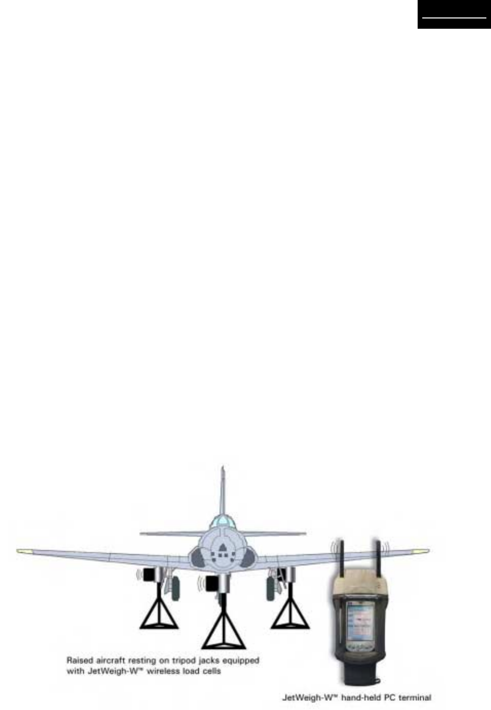
This manual provides information on the operation of
JetWeigh-W™ Wireless Aircraft Weighing System se-
ries aircraft electronic weighing kits manufactured by
Vishay SI Technologies. JetWeigh-W™ Wireless Air-
craft Weighing Systems (Figure 1-1) integrate state-
of-the-art wireless communication, digital weight pro-
cessing, and high-accuracy hermetically sealed load
cells. Combined technologies from Vishay Revere
Transducers and Vishay RFWaves results in an accu-
rate, high-reliability, robust, and easy to use Wireless
Aircraft Weighing System.
JetWeigh-W kits are designed primarily for the weigh-
ing of aircraft and aerospace vehicles, but can be
used for other precision weighing applications, as well
as for the calibration of force generating machines.
The kits have been calibrated using dead weight ma-
chines. These machines are maintained to better than
±0.001% with respect to the nominal weight value. The
degree of uncertainty for all of the individual weights
is approximately ±0.005% with respect to true values.
All readings are corrected to standard gravity factor
“g” as required by MlL-W-7327C.
High capacity JetWeigh-W kits with load cell capaci-
ties of 200,000 lb are calibrated on Vishay Revere’s
high capacity precision hydraulic transfer standard.
On completion of this calibration, the JetWeigh data is
verified on the dead weight machine up to the 100,000-
lb point. Maximum acceptable deviation between the
transfer standard and dead weight data is ±0.05%.
Both the dead weight machine and the transfer stan-
dard are secondary standards and are directly trace-
able to NIST.
It is recommended that the kit be returned to the fac-
tory for routine calibration every twelve (12) months or
sooner if trouble is observed or erroneous readings
are suspected.
The load imposed on a load sensor produces an
output signal directly proportional to the load applied.
The signal is transmitted through a wireless channel
to the JetWeigh handheld terminal where the mea-
surement is processed. Analog load sensor signals
are processed digitally to remove linearity errors,
latitude and altitude effects. Presentation in pounds
or kilograms is selectable by the operator. An
integral printer provides a permanent record of all
pertinent weighment information including any
deviations that are accepted by the operator.
Figure 1-1. Typical JetWeigh-W™ Aircraft Weighing System
Page 1-2
IntroductionIntroduction
IntroductionIntroduction
Introduction
1.2 SYSTEM COMPONENT
DESCRIPTIONS
Each kit contains the necessary equipment for weigh-
ing an aircraft with the exception of specialized jacks .
Kit contents include 3 to 5 wireless load cells, a rug-
ged handheld PC user terminal, a thermal printer, power
adaptors and a power cord, a center of gravity acces-
sory kit, and a rugged fiberglass carrying case.
1.2.1 Wireless Handheld Terminal
The wireless handheld PC terminal features a graphic
color touch screen display, intuitive step-by-step op-
eration, and advanced functions such as CG calcula-
tion, aircraft type library, weighing history, latitude and
altitude adjustment. It communicates with up to 5 re-
mote wireless load cells thereby eliminating cumber-
some interconnecting cables.
Units operate in a world wide license-free band - 2400
MHz to 2483.5 MHz and comply with all FCC, CE,
ETSI standards.
Synchronized sampling of all load cells ensures cor-
rect weighing even under severe vibration and oscilla-
tions conditions.
1.2.2 Wireless Load Cells
Each kit contains from 3 to 5 hermetically sealed wire-
less load cells. These cells are precision devices and
will withstand 150% overload without damage. Drop-
ping a load cell, however, could damage the elec-
tronic box, the diaphragm, or other components af-
fecting its operation or accuracy.
Each cell has a tapped hole on the bottom to receive a
plug or a ring jack adapter. The top surface has a ¾”
radius concave surface to receive either the spherical
surface of an adapter or the aircraft jack pad directly.
NOTE: Load cells of identical capacity are interchange-
able. However, load cells and spherical adapters are
color coded as matched sets. When changing load
cell locations, make sure that the spherical adapter/
load cell combination remains intact.
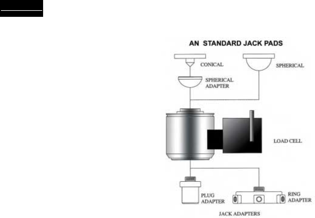
1.2.3 Load Cell Adapters
For the purpose of mounting load cells under varying
physical arrangements, several adapters are provided
(See Figure 1-2):
a) Plug and ring adapters for securing the cell to
the hydraulic jack.
Figure 1-2. Jack Adapters
b) Spherical adapters to allow interfacing transi-
tion between the cells and conical jack pads or
flat surfaces
c) Axle adapters which allow transition from the
cell to the cylindrical surface of the axle.
1.2.4 Thermal Printer
JetWeigh-W systems ship with a high speed thermal
printer. At the end of each weighment, aircraft specifi-
cations, resultant weight data, and all other calcula-
tions can be printed and stored for future reference.
The printer is compact, easy to install, and require
minimal maintenance. A complete reference manual
for the printer is included with the kit.

Page 2-1
Pre-operationPre-operation
Pre-operationPre-operation
Pre-operation
Section II - Pre-Operation
2.1 PRE-OPERATIONAL PROCEDURES
Section II presents all procedures that must be performed
prior to actual aircraft weighment. Since the JetWeigh-
W system is completely wireless, no cable connection/
installation procedures are required. With an operating
range of 220 feet (70 meters), it should be easy to lo-
cate all load cells and the handheld terminal in functional
proximity to one another.
2.1.1 Load Cell Jack Point Configuration
JetWeigh-W Systems accommodate jack point configu-
rations for 3-point, 4-point (helicopter or fixed wing) and
5-point aircraft. Recommended deployment of the load
cells is shown in Table 2-1. Make sure to match the load
cells and the mechanical adapters to ensure good re-
peatability of weighments.
2.1.2 Preparation for Aircraft Weighing
1. Review the Equipment List of the aircraft being
weighed. Update the list as required. Make sure the
particular equipment, which will normally be installed,
but is missing at the time of the weighing, is added in
the later calculations.
2. Remove all equipment, which will not be included in
the above list.
3. Clean the aircraft to remove accumulated dirt, grease
and trapped water.
4. Fill the oil tanks to a known quantity. Fill all reser-
voirs, such as anti-icing fluid, to capacity.
5. Drain fuel tanks. If draining is not practical, fill the
tanks to capacity. Add or account for unusable fuel.
6. Determine the unit weight of fuel. Obtain a sample
from the fuel tank with the supplied fuel dipper (CG
kit) and pour the sample into the test tube. Using the
hydrometers (CG kit), the weight of fuel in pounds per
gallon can be observed. Variations in fuel weight, par-
ticularly in the case of jet aircraft, can cause
appreciable difference in the final empty weight and
CG determinations. Be alert for partially filled non-
symmetrical fuel tanks.
7. With tricycle gear aircraft, it is often desirable to
level the aircraft as closely as possible before lifting
on the jacks. Changing oleo strut extensions can do
this.
8. A stabilizing period of 20 minutes running concur-
rently with warm-up period is advisable. When using
jack adapters, be sure the adapter is fully threaded into
the cell. With ring adapters, make sure it is centered
flush on the ram before tightening the set screws.
CAUTION
Use proper adapters to prevent jacks from
slipping or buckling. Damage to the aircraft or
inaccurate weight readings may result if improper
adapters are used. Never apply load to the rim of
the cell.
Color coded spherical adapters must be used in
conjunction with color coded load cells.
9. It is recommended that the load sensors be exer-
cised prior to performing an actual weighment.
Exercise the load sensors 2 – 3 times by lifting the
aircraft with the load sensors and jacking system in
place.
10. The JetWeigh-W is programmed to identify left,
right, nose, or the sum of both sensors on a bogie.
This requires that specific channels (load cells) be
dedicated to a specific location when preparing for
a weighment. These location identifiers will nor-
mally appear on the printout. However, they will not
appear during 1 and 2 channel operation. Table 2-1
shows the recommended layout for various configu-
rations.
3 Load Cells
Channel 1 Red Left
Channel 2 Yellow Right
Channel 3 Blue Nose
4 Load Cells Helicopter Fixed Wing
Channel 1 Red Fwd Left Left
Channel 2 Yel Fwd Right Right
Channel 3 Blue Aft Left Nose
Channel 4 Orng Aft Right Spare
5 Load Cells
Channel 1 Red Left (1)
Channel 2 Yellow Right (1)
Channel 3 Blue Left (2)
Channel 4 Green Right (2)
Channel 5 White Nose
Table 2-1. Jack Point Configuration
Page 2-2
Pre-operationPre-operation
Pre-operationPre-operation
Pre-operation
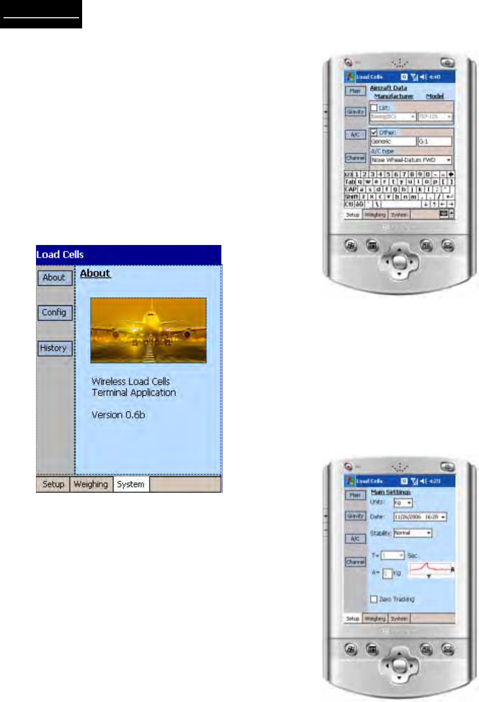
2.2 TERMINAL SETUP
Figure 2-1 shows the default power up screen for the
handheld terminal. Three primary function modes;
Setup, Weighing, and System, are accessed by touch-
ing the associated soft keys at the bottom of this screen.
In this Section, system setup is defined prior to actual
aircraft weighing. Touch (with stylus - throughout) setup
on the lower left corner of the screen to enter setup
mode. Vishay recommends that setup be performed
with the power adapter plugged in to conserve battery
charge for actual wireless weighment.
NOTE: The Handheld Terminal will operate for approxi-
mately eight hours on battery power alone.
2.2.1 Setup Screen Options
Setup mode consists of four sub-menu selections lo-
cated on the left side of the screen. Step through each
sub-menu sequentially, starting with
Main
and proceed-
ing to
Gravity
,
A/C
, and
Channel
. After entering valid
parameters for each sub menu, the system is ready
for “live” weighing operation.
NOTE: For screens that require data entry, touch the
data entry box and an alphanumeric keypad will ap-
pear as shown in Figure 2-2.
2.2.2 Main
Touch “
Main
” on the left margin of the screen to enter
fundamental system parameters (Figure 2-3).
a). Units – use the drop-down menu to select
lb (pounds) or kg (kilograms)
b). Date – use the drop-down menu to set the
correct date
Figure 2-1. Initial Power Up Display
Figure 2-2. Data Entry Keypad Displayed
Figure 2-3. Main Parameter Selections
Page 2-3
Pre-operationPre-operation
Pre-operationPre-operation
Pre-operation
c). Stability – use the drop-down menu to select
Normal, Relaxed, or User. Ambient air currents
always affect weighments to some extent. If the
aircraft is weighed indoors (hanger environment),
select normal to compensate for minor air current
uplift effects. If the plane is out of doors, select
relaxed (twice normal) to achieve slightly more
compensation. Selecting user allows specific time
and amplitude values to be entered for precise
compensation (see “d”).
d). “T” represents the duration period and “A” repre-
sents the amplitude of an interference that will
not be considered as a change in weight. As long
as the weight readings are within the rectangular
TxA, weight readings are considered to be stable.
e). Averaging - use the drop-down menu to select 1,
2, 5, 10, or 50 conversion averaging. Averaging
applies a low-pass filter on the weight readings to
eliminate the effect of vibrations.
f). Zero tracking – touch the Zero Tracking check box
to activate the zero tracking function. Zero
tracking eliminates minor electronic variations
around the calibrated zero value.
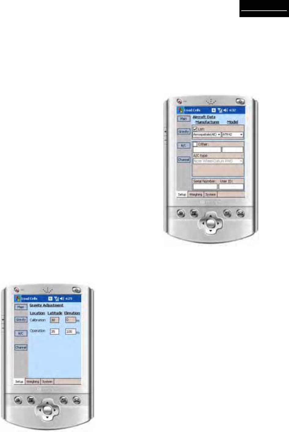
2.2.3 Gravity Factor Compensation
The Figure 2-4
Gravity
menu consists of two grayed out
text boxes that display the calibration location data, and
two enabled text boxes for entry of the operation latitude
and elevation. Enter the exact latitude and elevation of
your installation location.
2.2.4 A/C
The
A/C
menu (Figure 2-5) allows users to choose
from a predefined list of over 200 aircraft, or define
the dimensions of a custom (“Other”) aircraft. This
menu also allows the entry of the aircraft serial num-
ber and the user’s ID for printouts and future refer-
ence, if saved.
a). Touch list and then model to view aircraft types
and configurations.
b). Touch the “Other” checkbox to activate entry of
a new Manufacturer/Model combination. Key in
the manufacturer and model number in the
respective boxes beneath “Other”.
c). Use the A/C type drop-down menu to select the
new aircraft type.
d). Key in the serial number and user ID for the
new aircraft configuration. All entered informa-
tion will be included in the final weighment
printout.
Figure 2-4. Gravity Parameter Selections
Figure 2-5. Aircraft (A/C) Parameter Selections
Page 2-4
Pre-operationPre-operation
Pre-operationPre-operation
Pre-operation
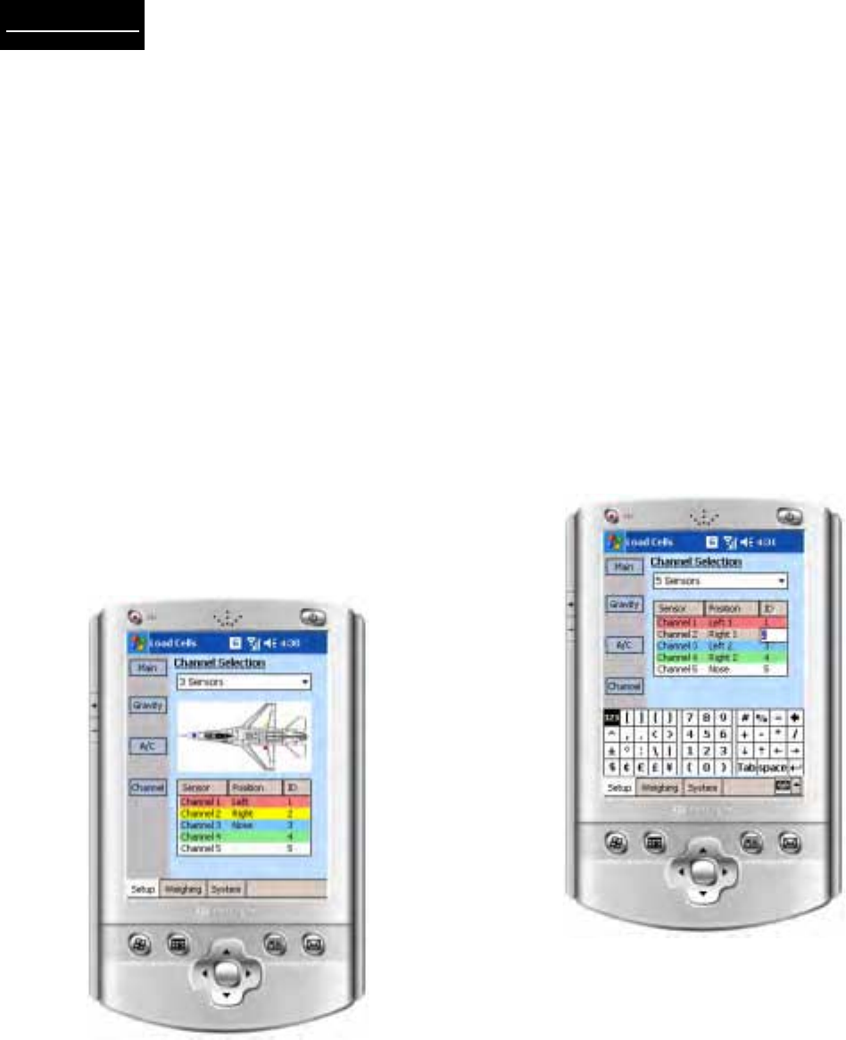
2.2.5 Channel
Touch the
Channel Selection
drop-down menu (Figure
2-6) to choose from one of five standard aircraft con-
figurations. The selections are:
a). 3 sensors (load cells – throughout)
b). 4 sensors – helicopter
c). 4 sensors – fixed wing aircraft
d). 5 sensors
After selection, the configuration is displayed as a
wheel-by-wheel, or jack point-by- jack point schematic
diagram and the channel allocation table reflects ex-
act placement locations. Double touching a channel
ID number changes the channel allocation table and
schematic to a new aircraft (based upon ID entry in
segment “d” of paragraph 2.2.4).
After completing all sequential parameter entries, the
JetWeigh-W System is ready for “live” weighing op-
eration.
Figure 2-6. Load Cell Channel Configuration
2.2.6 Changing Channel ID and Location
To change logical channels, as shown in Figure 2-7,
double click the ID field at the channel selection table.
This opens an editable field at that ID, and a numeric
keypad will pop up.
Using the numeric keypad, you can assign any chan-
nel to that location. Channel input termination is com-
pleted by touching the enter key on the numeric key-
pad.
NOTE: Users are responsible for maintaining the logi-
cal integrity of each assigned location ( making sure
that a single channel is allocated to a single location).
Figure 2-7. Changing Channel ID Information
Page 3-1
OperationOperation
OperationOperation
Operation
Section III - Operation
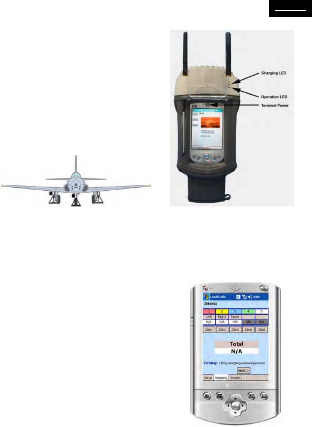
3.1 LOAD CELL POWER UP
Place load cell equipped jacks in position beneath air-
craft jack points as shown in Figure 3-1. Orient the
load cell transmitter housing (rectangular box attached
to the cylindrical cell) of each cell parallel to the neu-
tral axis of the aircraft. Walk to each cell and press the
power “ON” button. Check the green LED on each cell
transmitter housing to see that it is illuminated and
blinking at a rate of approximately one Hz (once per
second).
NOTE: If the green LED is blinking at a rapid rate, this
indicates that load cell internal battery capacity is low
- approximately one hour of work is left (without charg-
ing). Recharge the cell battery as soon as possible.
3.2 TERMINAL POWER UP
Figure 3-2 depicts the handheld terminal in its RF
equipped carrying case. Press the terminal power but-
ton and observe the initial screen as depicted at right.
NOTE: The Operation LED should remain in the off
state until actual weighment begins.
3.3 AIRCRAFT WEIGHING CYCLE
Prior to weighment, Vishay recommends that the air-
craft be raised and lowered 2 or 3 times (“dry runs”)
to acclimate system load cells. Actual weighing is ac-
complished in six steps; Zeroing, Lifting, Weighing,
Removing, Rezeroing, and Reporting using the weigh-
ing menu. Each step must be performed sequentially
and successfully before proceeding to the next step.
To begin, touch the
Weighing
menu block on the lower
tool bar with the stylus and observe the
Zeroing
screen
depicted in figure 3-3.
3.3.1 Zeroing
Under ideal conditions, with load cells powered up and
in a no load condition (no jack contact with aircraft
jack points) the reading for each channel should be
zero. However, in reality, it is often necessary to “zero
out” minor variances in any or all of the system cells.
The zeroing screen (Figure 3-3) allows for individual
or complete zeroing of any/all system cells.
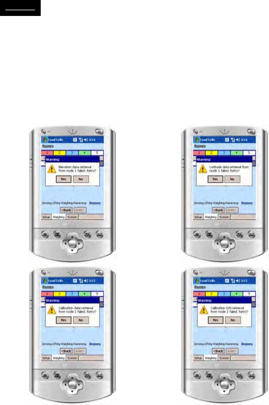
During the zeroing process, the terminal retrieves cali-
bration, serial number, and other critical data from
each load cell. If data cannot be accessed, one of the
Figure 3-4 error screens (next page) will appear. Any
weighment which does not include all vital data from
each cell will not be valid, so the user is prompted and
given the choice/chance to try again.
Figure 3-1. Aircraft with Jacks Positioned
Figure 3-3. Zeroing Screen/Menu
Figure 3-2. Handheld Terminal Enclosure
Page 3-2
OperationOperation
OperationOperation
Operation
Figure 3-4. Load Cell Data Not Acquired Messages
NOTE: A reading of NA for any valid channel indi-
cates that the load cell is malfunctioning or in the “OFF”
state. Zeroing is not valid. If the problem persists, re-
fer to the Section IV - Troubleshooting.
NOTE: When a poor RF link conditions exists, a red
antenna symbol will appear to the right of the channel
ID of the cell experiencing the problem, as shown in
Figure 3-5.
NOTE:
If a red “battery” symbol appears to the left of any
channel ID, the load cell battery must be recharged
and the zeroing process repeated.
Once zero is established, touch Next> to advance to
the lifting menu.
Page 3-3
OperationOperation
OperationOperation
Operation
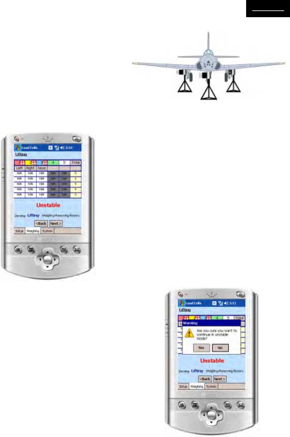
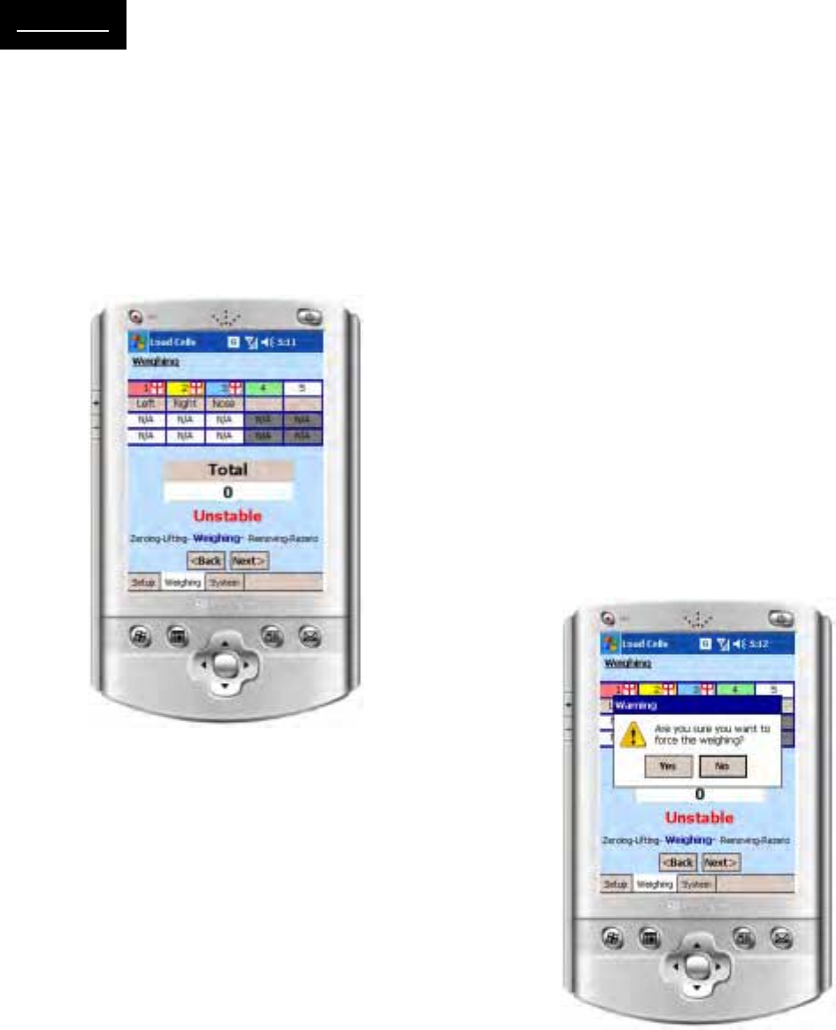
3.3.2 Lifting
At this juncture, the aircraft must be jacked up so that
it is resting exclusively on the load cell based jacks.
Jacking should be done in accordance with aircraft
manufacturer specifications, if provided. During the
jacking or lifting phase, the Lifting menu (Figure 3-5)
displays the successive measurements from all active
channels and indicates the stability of the measure-
ments. Once the aircraft is jacked up (Figure 3-6) and
readings are stable, touch Next> to advance to the
weighing screen.
If the weight readings are changing during lifting, a
warning “UNSTABLE” appears at the bottom of the
weights table. This is normal during the lifting process.
After the aircraft was fully jacked up and all vibrations
and oscillations ceased down this indication should
change to “STABLE”.
Should the “STABLE” condition not be reached after
a few minutes or in case of external causes (wind,
etc.), the user can force the system to proceed to the
WEIGHING stage by touching the NEXT> soft key. A
warning message will appear on the screen as shown
in Figure 3-7. To continue with forced operation touch
the “YES” key.
Figure 3-5. Screen Display During Lifting
Figure 3-6. Aircraft Fully Jacked
Figure 3-7. Weighing Lift Warning
NOTE: the unstable condition report will be included
in the final report and in the printout of the weighment
results.
NOTE: When a poor RF link conditions exists, a red
antenna symbol will appear to the right of the channel
ID of the cell experiencing the problem, as shown in
Figure 3-5.
NOTE:
If a red “battery” symbol appears to the left of any
channel ID, the load cell battery must be recharged
and the zeroing process repeated.
NOTE: If weight reading(s) for any channel(s) ap-
pear in a yellow box, less than 50% of the updates
required for averaging have been received. If weight
reading(s) for any channel(s) appear in a red box,
this indicates that the load cell(s) is in low power mode.
Turn off the terminal, recharge the low power cell(s),
and restart the terminal to clear the red data indica-
tion.
Page 3-4
OperationOperation
OperationOperation
Operation
3.3.3 Weighing
Weighing (Figure 3-8) displays the current weight and
percent of load readings for each channel (load cell).
Weight values for each channel are recorded on the
upper line with percentage equivalents directly beneath.
With a stable reading displayed, touch Next> to record
the weighment and advance to the Removing screen/
menu.
Should the “STABLE” condition not be reached after
a few minutes or in case of external causes (wind,
etc.), the user can force the system to proceed to the
Removing stage by touching the NEXT> soft key. A
warning message will appear on the screen as shown
in Figure 3-9. To continue with forced operation touch
the “YES” key.
.
Figure 3-8. Channel Weight and Percentage Values
NOTE:
The operator must be satisfied that the weighment
is valid in addition to the instruments “stable”
prompt. Operator acceptance takes into consider-
ation factors such as: the aircraft is completely clear
of the ground (floor) and all items aboard are ac-
counted for, etc. The scale will enter the “stable”
condition after an undisturbed period regardless of
the amount of load applied. The operator is free to
change the loading until a final weighment is ac-
ceptable on the display. Any outside force, wind on
control surfaces, vibration, etc., may keep the scale
from reaching a “stable” condition. It is important
for the operator to exercise good judgment at this
point. The scale can only recognize stability and
has no way to confirm that loading is complete and
acceptable.
Figure 3-9. Unstable Weighment Warning Screen
Page 3-5
OperationOperation
OperationOperation
Operation
3.3.4 Removing
Removing is the reverse of lifting. At this time, lower
the aircraft to its original resting position and make
sure there is no contact between the load cells and the
jack points. Touch Next> to advance to the rezeroing
menu.
3.3.5 Rezeroing
The rezeroing menu displays the after-weighment zero
reference for each cell. Ideally, all cells should return
to their original no-load zero value.
NOTE: DO NOT REMOVE ANY INTERFACE HARD-
WARE. It is important that all load sensors are clear
of the aircraft to provide a good zero return. The
JetWeigh-W performs automatic checks to assure a
good zero return (zero tracking if selected) and com-
pensate for minor tolerance variations during zero re-
turn. If the return is not satisfactory for any reason,
an error condition will result. The weighmaster must
review all error messages and the data on the printout
tape to decide if the weighment can be accepted or
the aircraft must be re-weighed.
Touch Next> to view a complete report of the aircraft
weighment cycle
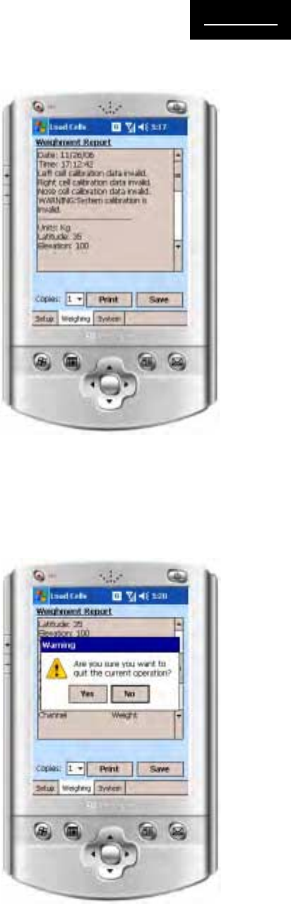
3.3.6 Weighment Report
Figure 3-10 depicts the screen view of a typical air-
craft weighment report. All calculations, aircraft identi-
fiers, and weighment results are available for visual
review and hard copy printout. Data may also be saved
for future reference by touching the screen “Save”
button.
If a data save is not desired/required, simply continue
without touching the save button. A message will ap-
pear asking the operator to confirm that data is not
being saved (Figure 3-11).
At this point, the weighment is complete. It is recom-
mended that load cell batteries and the handheld ter-
minal be recharged using the supplied power adapter
cords. Once recharging is complete, the system may
be readied for the next aircraft weighment or repacked
in its storage case.
Figure 3-11. Data Not Saved Warning Message
Figure 3-10. Typical Aircraft Weighing Report
Page 4-1
historyhistory
historyhistory
history
Section IV - Weighing History
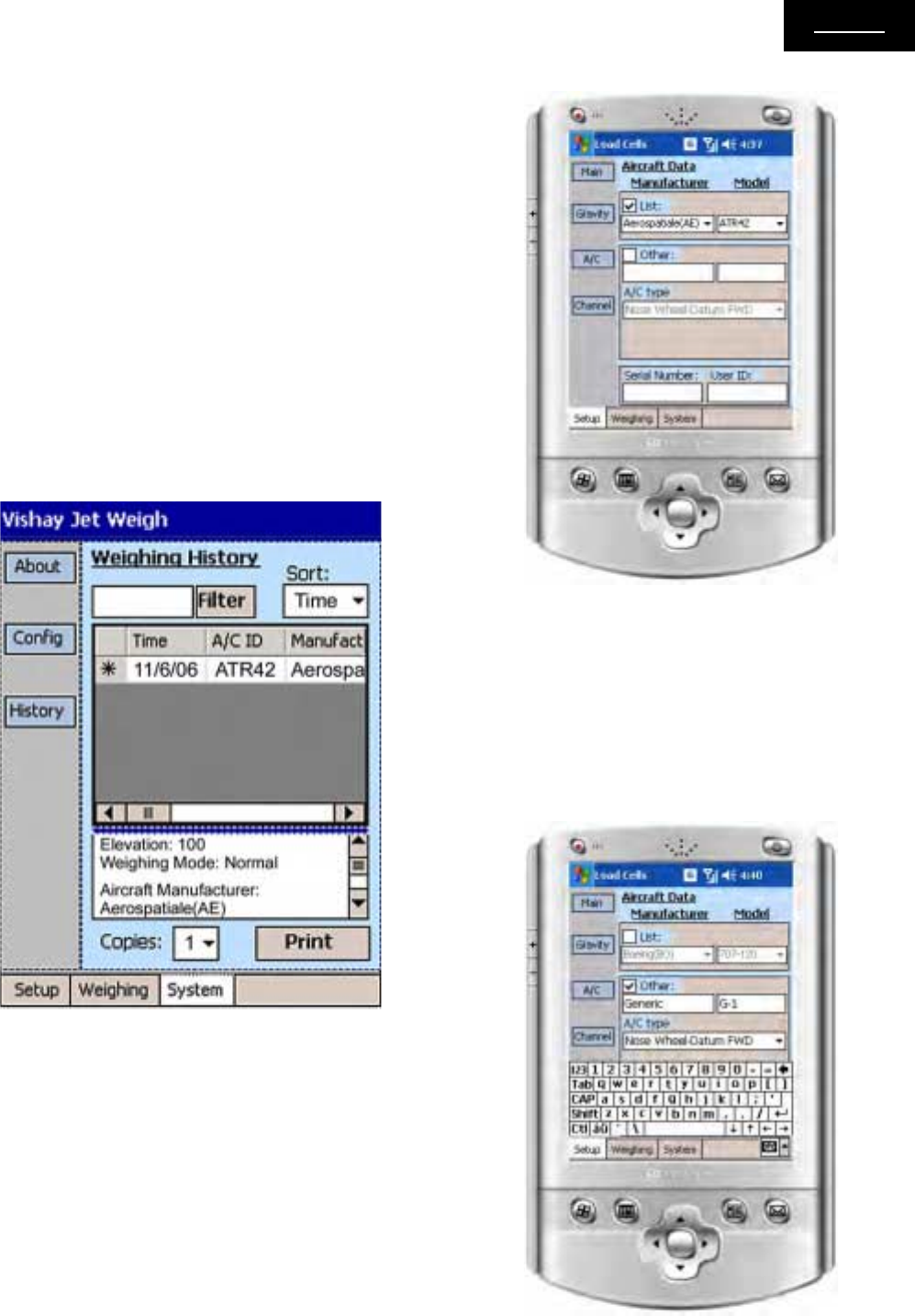
4.1 RECALL A RECORD FROM THE
HISTORY FILE
Access the “System” tab, and press “History” to get to
the history page display shown in Figure 4-1. The up-
per table displays a list of past reports. These reports
can be sorted by Time, by Aircraft ID, and by Serial
Number, using the “Sort:” drop down list. This table
also accesses reports belonging to a specific aircraft
by entering its serial number at the “filter” field and
touching the “Filter” button. To revert to the unfiltered
state, clear the filter field and touch the filter button.
The lower text box will display the report currently se-
lected at the history table. To print an aircraft data
report, connecting the handheld terminal to the printer
and touch the “Print” button.
4.2 RECALLING AIRCRAFT FROM THE
LIBRARY.
Many standard aircraft configurations are recorded in
the JetWeigh-W Library. To choose a configuration
from the library, view the drop down list at the Setup/
Aircraft Data page, as shown in Figure 4-2.
4.3 AIRCRAFT NOT RECORDED IN THE
LIBRARY
In order to use aircraft not available on the drop down
list, touch the “Other” check box, and input the aircraft
parameters manually, as shown in Figure 4-3.
Figure 4-1. JetWeigh-W History Screen
Figure 4-2. Recall Aircraft Screen
Figure 4-3. Input Aircraft Screen

Page 5-1
TroubleshootTroubleshoot
TroubleshootTroubleshoot
Troubleshoot
Section V - Troubleshooting
System
Status
Load Cell LED
State
Handheld Terminal
LED State
OFF OFF OFF
St and by Blinks Every 1.5
Sec. OFF
Weighing Always On Blinks Every 1.2 Sec.
Low Battery Blinks Every 0.5
Sec. Blinks Every 0.2 Sec.
Table 5-1. LED Status Indication
1.1 TROUBLESHOOTING OVERVIEW
Section V provides troubleshooting information for the
JetWeigh-W system. In many cases, simple battery
charging or recharging will resolve communication and
operation problems.
1.2 LED STATUS INDICATORS
Many operational problems can be resolved by noting
the LED status indicators on both the handheld termi-
nal case and each individual load cell. Table 5-1 de-
fines LED status indication for each device.
3.3 TYPICAL PROBLEMS AND
SOLUTIONS
Table 5-2 presents typical JetWeigh-W problems and
their simple solutions. As mentioned in paragraph 1.1,
simply checking the battery status on all devices and
recharging as needed resolves many JetWeigh-W
problems.
Problem/Error Cause Solution
No weighing results received form a
single load cell -1 Load cell is turned off Turn the load cell on and verify that it is
in standby mode
No weighing results received form a
single load cell -2 Load cell battery needs recharging
a). Check for a low battery indication at
the load cell and the terminal (see LED
Status Table 5-1)
b). Charge any/all low batteries
No weighing results received form a
single load cell -3 Poor wireless link
a). Move terminal closer to the load cell
b). Check the antenna connection on
the load cell
c). Change the RF channel in the
terminal
d). Improve the line-of-sight between
the terminal and the failing cell
e). Remove large metal objects from
the load cell vacinity
No weighing results received form all
load cells -1 Terminal is in low battery mode
a). Check for low battery indication at
terminal
b). Connect terminal to charger.
No weighing results received form all
load cells -2 Poor wireless link conditions
a). Check the antenna connection on
the terminal
b). Change the RF channel in the
terminal
A load cell doesn't turn on Load cell battery is drained out Connect the load cell to a charger
Handheld terminal doesn't turn on IPAQ battery is drained out Recharge IPAQ battery
Handheld terminal doesn't respond IPAQ Windows fault
Remove the IPAQ from the case and
perform a hardware reset using the
stylus pen. The reset key is on the back
of the IPAQ.
Table 5-2. JetWeigh-W Problems and Solutions
Page 5-2
troubleshoottroubleshoot
troubleshoottroubleshoot
troubleshoot
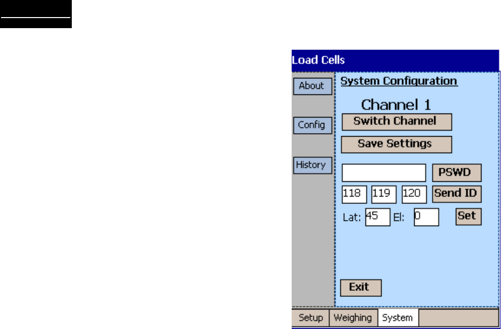
3.4 CHANGING RF CHANNELS
Communication problems are often resolved by switch-
ing to a different RF channel. Figure 5-1 shows the
Switch Channel button. Touching this button toggles
the label caption between channels. Save the optimal
channel settings by touching the Save Settings button.
Figure 5-1. Changing RF Channels

Contacting Vishay Systems
Americas
Vishay Systems Americas
The McMullen Building - 138 Baltimore St.
Suite 204, Cumberland, MD USA
PH: +1-301-722-6000
FAX: +1-301-722-7330
E-MAIL: vsi.usa@vishaymg.com
Vishay Systems Canada
#1106-1765 Springfield Rd., Kelowna, BC V1Y 5V5
Canada
PH: +1-800-989-1499; +1-250-860-8450
FAX: +250-762-9811
E-MAIL: vsi.can@vishaymg.com
Asia
Vishay Systems Taiwan (Asia except
China)
15 Fl, No. 86, Sec. 1 Shintal 5th Rd.
Sijhih City, Taipei, Taiwan 22102
PH: +886-2-2696-0168
FAX: +886-2-2696-4965
E-MAIL: vs.roc@vishaymg.com
Vishay Systems China
No. 5 Binguan Nan Dao Youyi Rd., Hexi District,
Tianjin China, Code 300061
PH: +86-22-2835-3503
FAX: +86-22-2835-7261
E-MAIL: vs.prc@vishaymg.com
Europe
Vishay Systems Germany
Tatschenweg 1, 74078
Heilbronn, Germany
PH: +49-7131-3901-260
FAX: +49-7131-3901-2666
E-MAIL: vs.de@vishaymg.com
Vishay Systems UK
Stroudley Road, Basingstoke, Hampshire
RG24 8FW, United Kingdom
PH: +44-125-646-2131
FAX: +44-125-647-1441
E-MAIL: vs.uk@vishaymg.com
Vishay Systems France
16 Rue Francis Vovelle, 28000 Chartres, France
PH: +33-2-37-33-31-20
FAX: +33-2-37-33-31-29
E-MAIL: vs.fr@vishaymg.com
Vishay Systems Norway
Brobekkveien 80, 0582 Oslo,
Norway
PH: +47-22-88-40-90
FAX: +47-22-88-40-99
E-MAIL: vs.se@vishaymg.com
Vishay Systems Sweden
P.O. Box 423, SE-691 27 Karlskoga, Sweden
PH: +46-586-63000
FAX: +46-586-63099
E-MAIL: vs.se@vishaymg.com
Vishay Systems Israel
8A Hazoran Street, P.O. Box 8381,
New Industrial Zone, Netanya 42506, Israel
PH: +972-9-863-8888
FAX: +972-9-863-8800
E-MAIL: vs.il@vishaymg.com