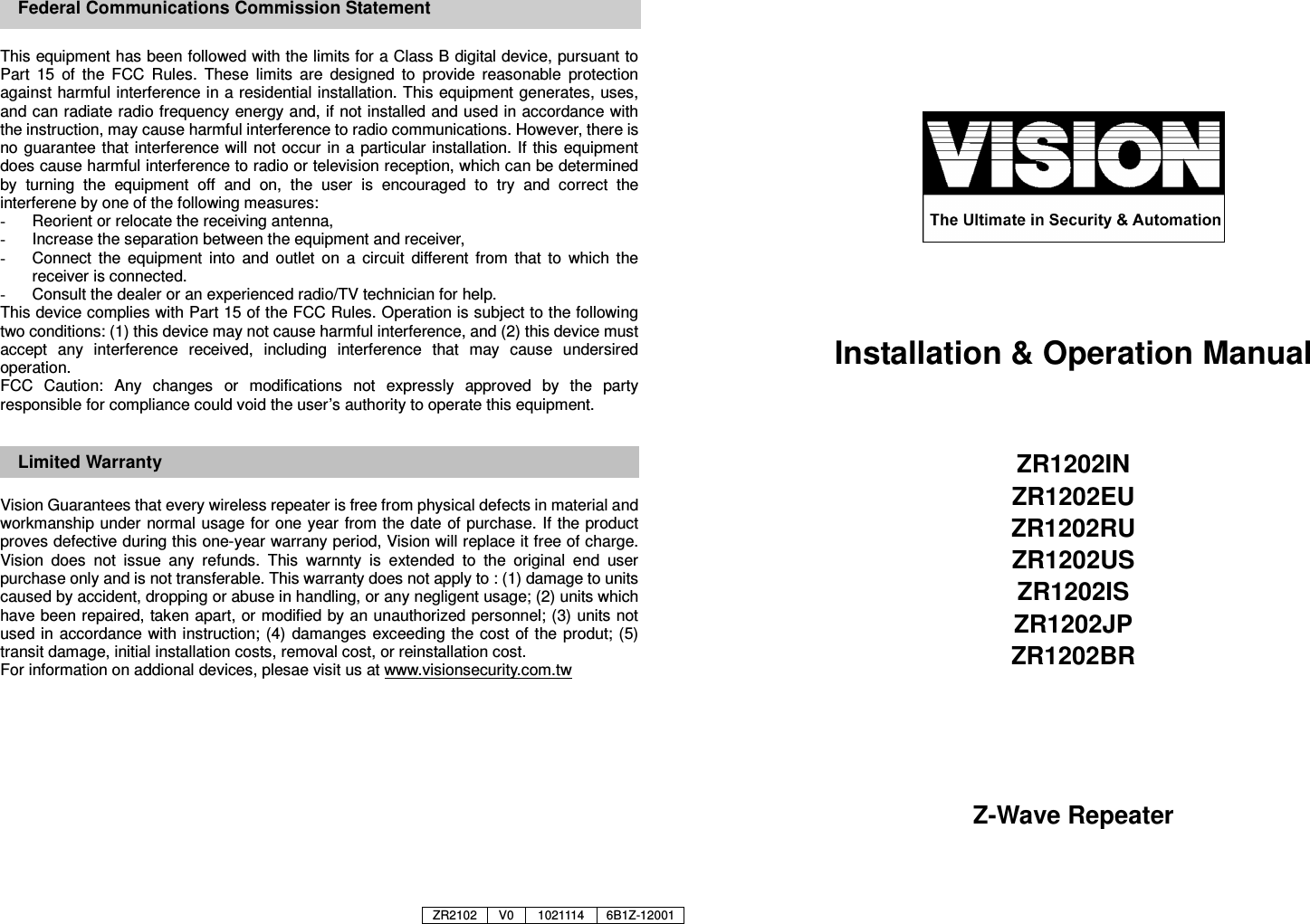
Vision Automobile Electronics Co ZR1202US Z-Wave Repeater User Manual

Vision Automobile Electronics Industrial Co Ltd Z-Wave Repeater

User manual

     This equipment has been followed with the limits for a Class B digital device, pursuant to Part  15  of  the  FCC  Rules.  These  limits  are  designed  to  provide  reasonable  protection against harmful interference in a residential installation. This equipment generates, uses, and can radiate radio frequency energy and, if not installed and used in accordance with the instruction, may cause harmful interference to radio communications. However, there is no guarantee that interference will not occur  in a particular  installation. If  this equipment does cause harmful interference to radio or television reception, which can be determined by  turning  the  equipment  off  and  on,  the  user  is  encouraged  to  try  and  correct  the interferene by one of the following measures: -  Reorient or relocate the receiving antenna, -  Increase the separation between the equipment and receiver, -  Connect  the  equipment  into  and  outlet  on  a  circuit  different  from  that  to  which  the receiver is connected. -  Consult the dealer or an experienced radio/TV technician for help. This device complies with Part 15 of the FCC Rules. Operation is subject to the following two conditions: (1) this device may not cause harmful interference, and (2) this device must accept  any  interference  received,  including  interference  that  may  cause  undersired operation. FCC  Caution:  Any  changes  or  modifications  not  expressly  approved  by  the  party responsible for compliance could void the user’s authority to operate this equipment.  Limited Warranty  Vision Guarantees that every wireless repeater is free from physical defects in material and workmanship under normal usage for one year  from the date of purchase. If  the product proves defective during this one-year warrany period, Vision will replace it free of charge. Vision  does  not  issue  any  refunds.  This  warnnty  is  extended  to  the  original  end  user purchase only and is not transferable. This warranty does not apply to : (1) damage to units caused by accident, dropping or abuse in handling, or any negligent usage; (2) units which have been repaired, taken apart, or modified by an unauthorized personnel; (3) units not used in  accordance with instruction; (4) damanges exceeding the cost  of the produt; (5) transit damage, initial installation costs, removal cost, or reinstallation cost. For information on addional devices, plesae visit us at www.visionsecurity.com.tw               Installation & Operation Manual   ZR1202IN ZR1202EU ZR1202RU ZR1202US ZR1202IS ZR1202JP ZR1202BR       Z-Wave Repeater   Federal Communications Commission Statement ZR2102 V0 1021114 6B1Z-12001
 Introduction Thanks  for choosing the Vision’s repeater of  the  home  automation device.  This module  is  a  Z-Wave™  enabled  device  (interoperable,  two-way  RF  mesh networking  technology)  and  is  fully  compatible  with  any  Z-Wave™  enabled network. Every main powered Z-Wave enabled device acts as a signal repeater and  multiple  devices  result  in  more  possible  transmission  routes  which  helps eliminate “RF dead-sports” Z-Wave™ enabled devices displaying the Z-Wave™ logo can also be used with it regardless of the manufacturer, and ours can also be used in other manufacturer’s Z-Wave™ enabled networks. This device take existing Z-WAVE signal, repeat and send it to a longer range where it is too far away for the controller (supporting FLiRS devices). Product Description and Specification *** For indoor use only ***                   Specification: Package Content: Protocol: Z-Wave™ (ZM4101) Frequency Range:   865.22MHz (ZR1202IN) 868.42MHz (ZR1202EU) 869.00MHz (ZR1202RU) 908.42MHz (ZR1202US) 916.00MHz (ZR1202IS) 920-928MHz(ZR1202JP) 921.42MHz (ZR1202BR) Operating Range: Up to 200 meters Operating Temp.: -15°C~ 60°C (5°F ~140°F) Operating Voltage: 5V/DC Current Consumption: 300mA (±50mA)  1pc 1pc       1pc 1pc ZR1202 Repeater module ZR1202 Repeater Bracket Adapter (Optional) Installation & Operation Manual   Z-Wave™ Command Class: COMMAND_CLASS_BASIC COMMAND_CLASS_MANUFACTURER_SPECIFIC COMMAND_CLASS_POWERLEVEL COMMAND_CLASS_VERSION  ※※※※Note: Suitable adapter specification:               -Micro USB Power Input -Operating Voltage: 5V/DC -Current Consumption: 500m  Installation Notice: If you are installing the entire Z-Wave™ system for the first time, please refer to the installation guide of Z-Wave™ Interface Controller before installing ZR 1202 Repeater Module.  1.  Fix  the  repeater  under  the  vertical  way  as  high  as  possible  then  insert  the suitable  Micro  USB Power  Adaptor  to  the  ZR1202  then  it  will  go  to  the Learning  Mode  automatically.  (The  LED  will  start  flash  which  means  the repeater has not been “Include” yet.)    2.  For  “Inclusion”  in  (adding  to)  a  network:  Put  the  Z-Wave™  Interface Controller  into“inclusion”  mode  and  following  its  instruction  to  add  the ZR1202  to  your  controller.  To  get  in  the  “inclusion”  mode,  the  distance between  module  and  controller  is  suggested  to  be  in  one  meter.  Press  the program  switch  on the ZR1202  once.  The  LED  should  stop flashing,  if not, please try again.    For “Exclusion” from (removing from) a network: Put the Z-Wave™ Interface Controller  into  “exclusion”  mode,  and  following  its  instruction  to  delete  the ZR1202 from your controller. Press the program switch on the ZR1202 once to be excluded. Note: LED setting light will flash continuously in Exclusion condition.  3.  Use  “Power  Level  Set”  command  for  setting  the  strength  of  RF  during  one period.      4.  Use “Power Level Test Node Set” command to test the direct signal for fixed node.  5.  Support Repeaters for routing (FLiRS included)  6.  Support Explorer Frame function   7.  Press  Program Switch  for 5 seconds, the  ZR1202 will reset  back to  factory default.     ★★★★  The ZR1202 operating range will be up to 200 meters under the correct installation!!    (2) (1)  Micro USB Power Input Program Switch Release the bracket: (1) Press (2) Slide down to release the bracket -1 -                                                                     -2 -

Navigation menu