Visiplex VTX1 Radio Transceiver User Manual
Visiplex, Inc. Radio Transceiver Users Manual
Visiplex >
Users Manual

Version: 1.00
VTX-1 Radio Transceiver - User Manual
The VTX-1 radio transceiver is designed to receive and transmit wireless analog & digital data and is designed to be used in
VISIPLEX products (such as paging encoders, data repeaters, wireless intercom controllers, etc.). The VTX-1 is typically
mounted inside the VISIPLEX host product and connected to its controller board using the Data & Power Interface 8-pin
cable. The VTX-1 unit is fully contained and no external adjustments are provided.
Programming of the VTX-1 parameters is performed via the USB port using commands sent via the PC serial port to the
VTX-1 host controller. The serial commands are sent using serial communication utilities such as HyperTerminal.
After programming is completed and the VTX-1 is mounted in to the VISIPLEX product, the USB port is not accessible to the
typical end user.
Note: The programming commands are available only to in-house radio technicians or external radio professionals familiar
with FCC restrictions under KDB 594280 to ensure compliance with FCC regulations.
Licensing
Some frequency bands governed by FCC rules require that the radio owner obtain a station license before using the
equipment to transmit. The station license holder is also responsible for the proper operation and maintenance of the VTX-1.
Note: The host end product label must include the following text: "Contains FCC ID: 2AAFWVTX1"
Safety
Please refer to RF Radiation Hazard Warning under Notice to User Regarding Radio Frequency Interference section for
information regarding RF radiation and recommended operation guidelines.
Version: 1.00
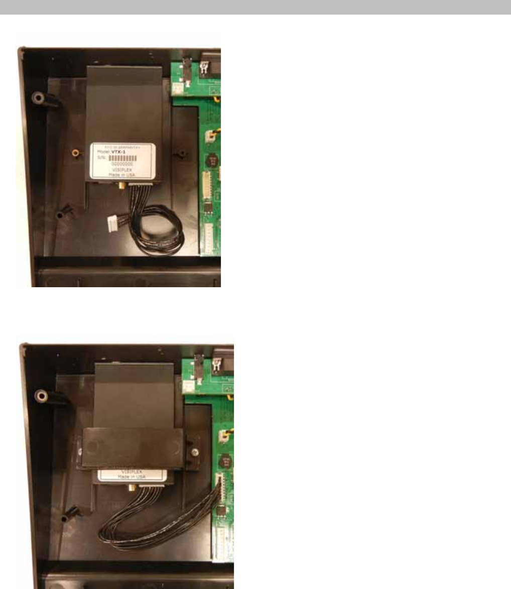
Typical Installation (Host product)
1. Mount the VTX-1 in the host product enclosure
2. Secure the VTX-1 using the applicable bracket and connect the Data & Power Interface cable to the host product main
board
Version: 1.00
3. Complete final assembly of host product. Verify connectivity and test for proper operation.
Version: 1.00
Specifications
Frequency Range 406.1 - 470 MHz
Channel Spacing 12.5 kHz
Frequency Control PLL
Frequency Stability 2.5 ppm
RF Power Output 19.4 dBm
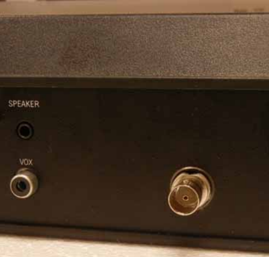
RF Output Connector BNC
RF Input Connector SMA
RF Load Impedance 50 Ohms
Recommended Antenna 3 dBi, Omni-Directional, Vertical Polarization
Power 5 VDC 1A
Power & Data Interface 8 Pin / USB Type B
Approvals FCC: 2AAFWVTX1
Operating Temperature 14º to 122º F / -10º to 50º C
Dimensions (W x H x D) 4" x 2.125" x 0.75" / 102mm x 54mm x 19mm (Connectors Included)
Weight 0.2 lbs.
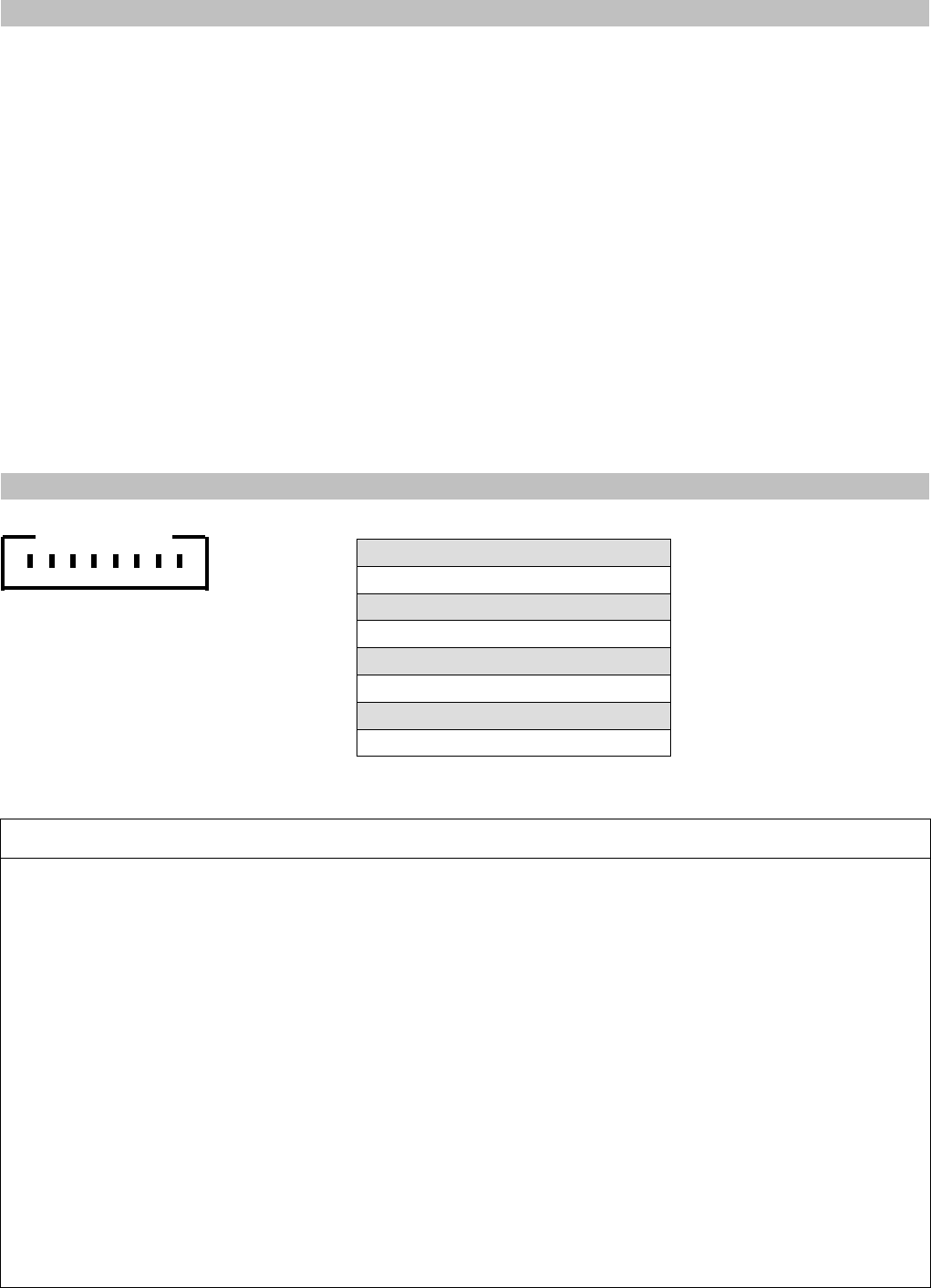
Data & Power Interface Pin Out
Notice to User Regarding Radio Frequency Interference (Class B)
This device complies with part 15 of the FCC Rules. Operation is subject to the following two conditions: (1) This device
may not cause harmful interference, and (2) this device must accept any interference received, including interference that
may cause undesired operation.
Changes or modifications not expressly approved by the party responsible for compliance could void the user's authority
to operate the equipment.
NOTE: This equipment has been tested and found to comply with the limits for a Class B digital device pursuant to Part 15
of the FCC Rules. These limits are designed to provide reasonable protection against harmful interference in a residential
installation. This equipment generates, uses, and can radiate radio frequency energy and, if not installed and used in
accordance with the instructions, may cause harmful interference to radio communications. However, there is no
guarantee that interference will not occur in a particular installation. If this equipment does cause harmful interference to
radio or television reception, which can be determined by turning the equipment off and on, the user is encouraged to try
and correct the interference by one or more of the following measures:
-Reorient or relocate the receiving antenna.
-Increase the separation between the equipment and the receiver.
-Connect the equipment into an outlet on a circuit different from that to which the receiver is connected.
-Consult the dealer or an experienced radio/TV technician for help.
RF Radiation Hazard Warning: To ensure compliance with FCC RF exposure requirements, the recommended minimum
lateral distance from the transmitting antenna is 30 cm from your body or nearby persons during continuous use.
1 - DC POWER (5V Input)
2 - PTT (Push to Talk Input)
3 - DATA IN (Data/Audio Input)
4 - RX (Digital Data Input)
5 - DATA OUT (Data/Audio Output)
6 - DCD (Carrier Detect Output)
7 - TX (Digital Data Output)
8 - GND (Ground)
8 7 6 5 4 3 2 1