Visonic MCM140 15.231 Security / Remote Control Transmitter User Manual
Visonic Inc. 15.231 Security / Remote Control Transmitter Users Manual
UserManual.wiki
>
Visonic
>
MCM140 User Manual
Users Manual
Navigation menu
Upload a User Manual
Namespaces
Wiki Guide
HTML
PDF
Info
Views
User Manual
Discussion / Help
Navigation
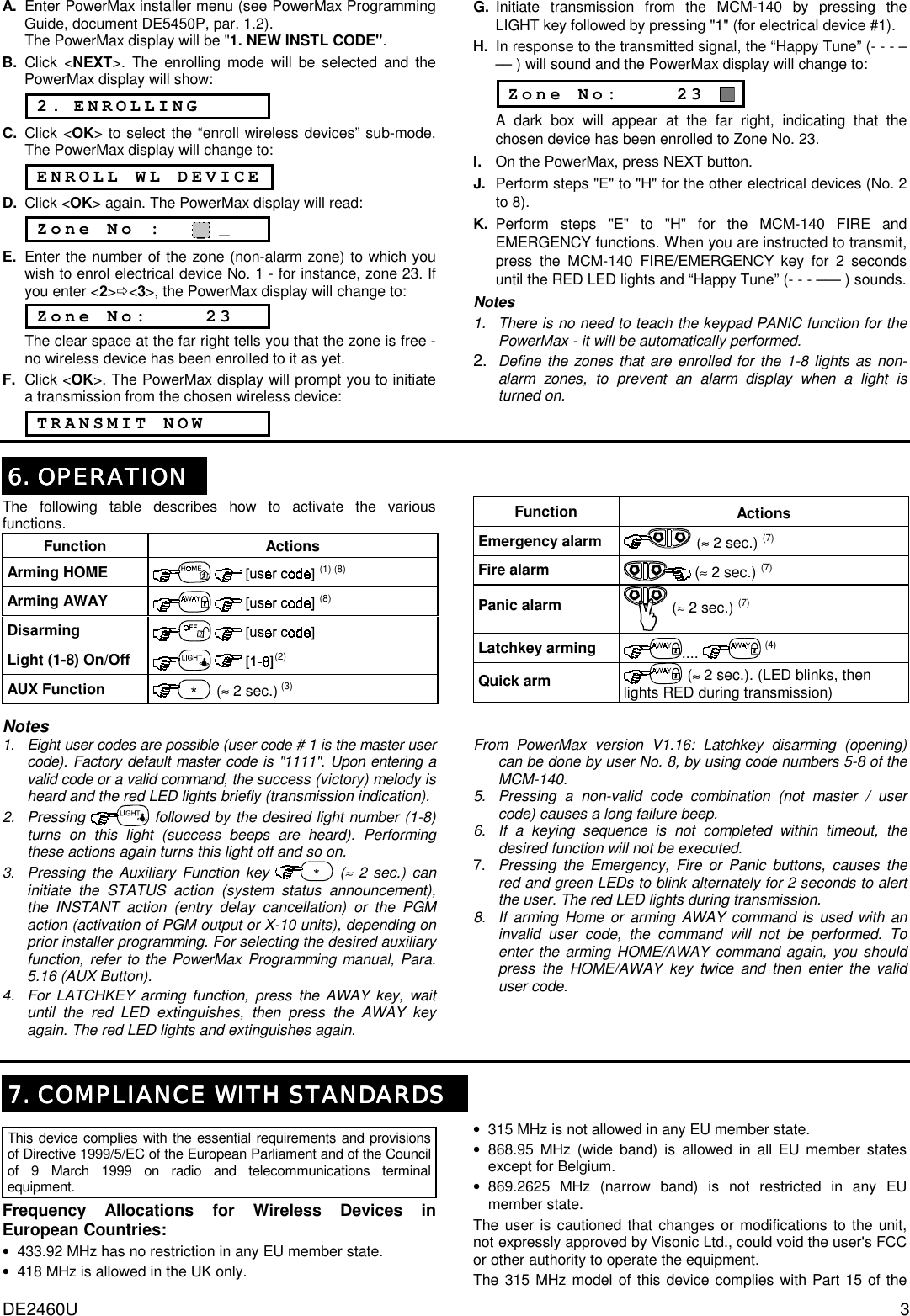
![2 DE2460U 4. PROGRAMMING4. PROGRAMMING4. PROGRAMMING4. PROGRAMMING 4.1 Programming Scope The following programming actions are possible: • Setting the master user (user #1) code. • Setting other user codes (users #2-8). • Allowing/forbidding quick arming of the keypad. • Muting/reactivating the keypad's buzzer. • Controlling the keypad's back-lighting. • Enabling/disabling the supervision/low battery reporting from the MCM-140. 4.2 Entering the Programming Mode The programming mode is accessible with the master code only (1 1 1 1 by default). The "#" key is used to enter and also to exit the programming mode. Entering the Programming Mode Action LED indication Buzzer response + Green LED blinks slowly until the master code is keyed * +[master code] (1111 by default) Amber LED blinks slowly during programming * (success melody) * Upon entering the programming mode, the success melody is heard and the amber LED starts blinking. Blinking will stop once you exit from this mode (by pressing "#" again) or upon time out during which no key is pressed. 2 short beeps are heard when the LED stops blinking. 4.3 Changing Master/User Codes To change the MCM-140 master and user codes, enter the programming mode (Par. 4.2) and proceed as follows: Action LED indication Buzzer response +[1-8]1 Amber LED blinks +[new code]2 Amber LED blinks quickly - (blinks slowly after success) (success melody) Notes 1. Enter user No. (1-8). User No. 1 is defined as the master user. 2. Master/user codes consist of 4-digits. Code "0000" is not valid. It can be used to erase the currently programmed code (when this action is performed, success melody is heard). 3. PowerMax user codes and MCM-140 user codes are different codes. 4.4 Restoring the Default Master Code If the master code is forgotten, it is possible to recall the factory default master code "1111". To ensure that this possibility is not misused by unauthorized people, a panic alarm is automatically transmitted to the PowerMax system when such an action is performed. To recall the default master code and prevent a panic alarm, set PowerMax to User Settings mode (see PowerMax Prog. Guide, Par. 1.2) and proceed as shown in the following illustration: 4.5 Special Programming Options Enter the programming mode (Par. 4.2) and proceed as follows: Desired function Press and then press: Quick arming 9 1 Buzzer control 9 2 +AWAY to enable (amber LED lights) Back lighting 9 3 +OFF to disable (amber LED blinks). Supervision / low battery reporting (only by using Fire button) 9 4 In both cases, the buzzer sounds twice, to indicate success. Notes: The supervision message will be sent once an hour. When there is Low Bat condition, trouble message will be displayed in the zone that was selected for the FIRE key. 5. ENROLLING THE MCM5. ENROLLING THE MCM5. ENROLLING THE MCM5. ENROLLING THE MCM----140 TO THE POWERMAX140 TO THE POWERMAX140 TO THE POWERMAX140 TO THE POWERMAX 5.1 Enrolling CodeSecure Functions To enroll the MCM-140 CodeSecure functions (Home/Away arming, Disarming, Aux and Panic functions), proceed as follows: A. Enter PowerMax installer menu (see PowerMax Programming Guide, document DE5450P, par. 1.2). The PowerMax display will be "1. NEW INSTL CODE". B. Click <NEXT>. The enrolling mode will be selected and the PowerMax display will show: 2. ENROLLING C. Click <OK>. The PowerMax display will change to: ENROLL WL DEVICE D. Click <NEXT>. The PowerMax display will read: ENROLL KEYFOB E. Click <OK>. The PowerMax display will read: Keyfob No: _ F. Press the key on the PowerMax keypad that corresponds with the location (1-4) that you wish to enroll in (assuming that the PowerMax memory locations No. 1, 2, 3 and 4 are free - no keyfob has yet been enrolled to them). If, for example, you have pressed the "1" key of the PowerMax keypad, the PowerMax display will change to: Keyfob No: 1 The clear space at the far right tells you that the memory location is free. G. Click <OK>. The PowerMax display will prompt you to initiate a transmission from the MCM-140: TRANSMIT NOW H. Initiate a transmission from the MCM-140 by pressing the "∗" button for 2 sec. approximately. As a result, the “Happy Tune” (- - - –––) will sound and the PowerMax display will change to: Keyfob No: 1 A dark box will appear at the far right, indicating that the chosen function has been enrolled. Note: If the same function is already enrolled elsewhere, the “Happy Tune” will sound twice in succession. 5.2 Enrolling PowerCode Functions The following MCM-140 PowerCode control functions can be enrolled: • Lights No. 1-7 • Light No. 8 (controlled by PGM, "on by zones") • Fire • Emergency To enroll these functions, proceed as follows:](https://usermanual.wiki/Visonic/MCM140/User-Guide-236824-Page-2.png)