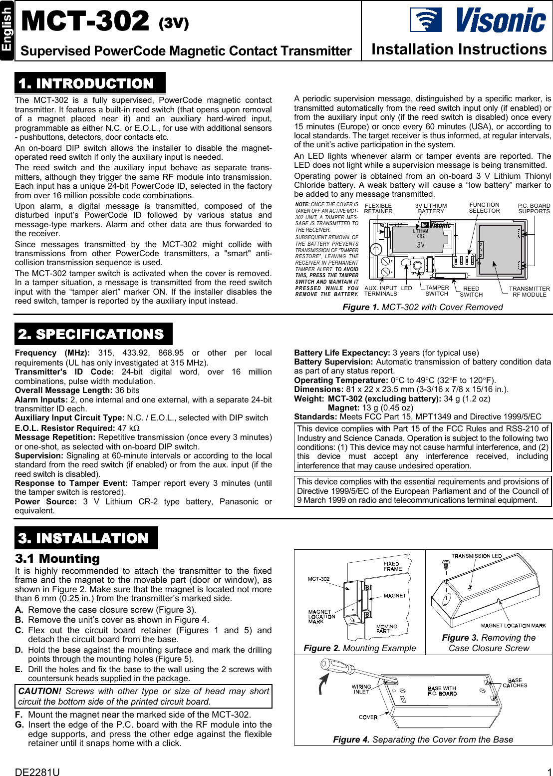
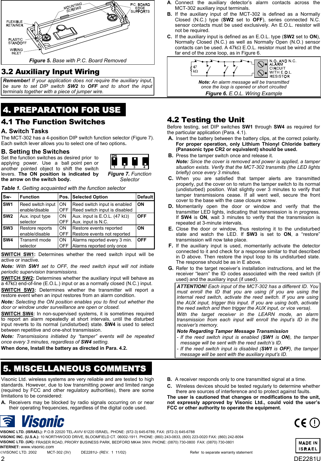
Visonic MCT3023V Supervised PowerCode Magnetic Contact Transmitter User Manual DE2281U1

Visonic Inc. Supervised PowerCode Magnetic Contact Transmitter DE2281U1

Exhibit D Users Manual per 2 1033 b3

DE2281U 1MCTMCTMCTMCT-302-302-302-302    ((((3333V)V)V)V)Supervised PowerCode Magnetic Contact Transmitter Installation Instructions1111. INTRODUCTION. INTRODUCTION. INTRODUCTION. INTRODUCTIONThe MCT-302 is a fully supervised, PowerCode magnetic contacttransmitter. It features a built-in reed switch (that opens upon removalof a magnet placed near it) and an auxiliary hard-wired input,programmable as either N.C. or E.O.L., for use with additional sensors- pushbuttons, detectors, door contacts etc.An on-board DIP switch allows the installer to disable the magnet-operated reed switch if only the auxiliary input is needed.The reed switch and the auxiliary input behave as separate trans-mitters, although they trigger the same RF module into transmission.Each input has a unique 24-bit PowerCode ID, selected in the factoryfrom over 16 million possible code combinations.  Upon alarm, a digital message is transmitted, composed of thedisturbed input’s PowerCode ID followed by various status andmessage-type markers. Alarm and other data are thus forwarded tothe receiver.Since messages transmitted by the MCT-302 might collide withtransmissions from other PowerCode transmitters, a "smart" anti-collision transmission sequence is used.The MCT-302 tamper switch is activated when the cover is removed.In a tamper situation, a message is transmitted from the reed switchinput with the “tamper alert” marker ON.  If the installer disables thereed switch, tamper is reported by the auxiliary input instead.A periodic supervision message, distinguished by a specific marker, istransmitted automatically from the reed switch input only (if enabled) orfrom the auxiliary input only (if the reed switch is disabled) once every15 minutes (Europe) or once every 60 minutes (USA), or according tolocal standards. The target receiver is thus informed, at regular intervals,of the unit’s active participation in the system.An LED lights whenever alarm or tamper events are reported. TheLED does not light while a supervision message is being transmitted.Operating power is obtained from an on-board 3 V Lithium ThionylChloride battery. A weak battery will cause a “low battery” marker tobe added to any message transmitted.FUNCTIONSELECTORTRANSMITTERRF MODULETAMPE RSWITCHAUX. INPUTTERMINALS3V LITHIUMBATTERYREEDSWITCHLEDFLEXIBLERETAINERP. C .  B O A R DSUPPORTSNOTE: ONCE THE COVER ISTAKEN OFF AN ACTIVE MCT-302 UNIT, A TAMPER MES-SAGE IS TRANSMITTED TOTHE RECEIVER.SUBSEQUENT REMOVAL OFTHE BATTERY PREVENTSTRANSMISSION OF “TAMPERRESTORE”, LEAVING THERECEIVER IN PERMANENTTAMPER ALERT. TO AVOIDTHIS, PRESS THE TAMPERSWITCH AND MAINTAIN ITPRESSED WHILE YOUREMOVE THE BATTERY.Figure 1. MCT-302 with Cover Removed2222. SPECIFICATIONS. SPECIFICATIONS. SPECIFICATIONS. SPECIFICATIONSFrequency (MHz): 315, 433.92, 868.95 or other per localrequirements (UL has only investigated at 315 MHz).Transmitter's ID Code: 24-bit digital word, over 16 millioncombinations, pulse width modulation.Overall Message Length: 36 bitsAlarm Inputs: 2, one internal and one external, with a separate 24-bittransmitter ID each.Auxiliary Input Circuit Type: N.C. / E.O.L., selected with DIP switchE.O.L. Resistor Required: 47 kΩMessage Repetition: Repetitive transmission (once every 3 minutes)or one-shot, as selected with on-board DIP switch.Supervision: Signaling at 60-minute intervals or according to the localstandard from the reed switch (if enabled) or from the aux. input (if thereed switch is disabled).Response to Tamper Event: Tamper report every 3 minutes (untilthe tamper switch is restored).Power Source: 3 V Lithium CR-2 type battery, Panasonic orequivalent.Battery Life Expectancy: 3 years (for typical use)Battery Supervision: Automatic transmission of battery condition dataas part of any status report.Operating Temperature: 0°C to 49°C (32°F to 120°F).Dimensions: 81 x 22 x 23.5 mm (3-3/16 x 7/8 x 15/16 in.).Weight: MCT-302 (excluding battery): 34 g (1.2 oz)Magnet: 13 g (0.45 oz)Standards: Meets FCC Part 15, MPT1349 and Directive 1999/5/ECThis device complies with Part 15 of the FCC Rules and RSS-210 ofIndustry and Science Canada. Operation is subject to the following twoconditions: (1) This device may not cause harmful interference, and (2)this device must accept any interference received, includinginterference that may cause undesired operation.This device complies with the essential requirements and provisions ofDirective 1999/5/EC of the European Parliament and of the Council of9 March 1999 on radio and telecommunications terminal equipment.3333. INSTALLATION. INSTALLATION. INSTALLATION. INSTALLATION3.1 MountingIt is highly recommended to attach the transmitter to the fixedframe and the magnet to the movable part (door or window), asshown in Figure 2. Make sure that the magnet is located not morethan 6 mm (0.25 in.) from the transmitter’s marked side.A. Remove the case closure screw (Figure 3).B. Remove the unit’s cover as shown in Figure 4.C. Flex out the circuit board retainer (Figures 1 and 5) anddetach the circuit board from the base.D. Hold the base against the mounting surface and mark the drillingpoints through the mounting holes (Figure 5).E. Drill the holes and fix the base to the wall using the 2 screws withcountersunk heads supplied in the package.CAUTION! Screws with other type or size of head may shortcircuit the bottom side of the printed circuit board.F. Mount the magnet near the marked side of the MCT-302.G. Insert the edge of the P.C. board with the RF module into theedge supports, and press the other edge against the flexibleretainer until it snaps home with a click.Figure 2. Mounting ExampleFigure 3. Removing theCase Closure ScrewFigure 4. Separating the Cover from the Base
2DE2281UFigure 5. Base with P.C. Board Removed3.2 Auxiliary Input WiringRemember! If your application does not require the auxiliary input,be sure to set DIP switch SW2 to OFF and to short the inputterminals together with a piece of jumper wire.A. Connect the auxiliary detector’s alarm contacts across theMCT-302 auxiliary input terminals.B. If the auxiliary input of the MCT-302 is defined as a NormallyClosed (N.C.) type (SW2 set to OFF), series connected N.C.sensor contacts must be used exclusively. An E.O.L. resistor willnot be required.C. If the auxiliary input is defined as an E.O.L. type (SW2 set to ON),Normally Closed (N.C.) as well as Normally Open (N.O.) sensorcontacts can be used. A 47kΩ E.O.L. resistor must be wired at thefar end of the zone loop, as in Figure 6.Note: An alarm message will be transmittedonce the loop is opened or short circuitedFigure 6. E.O.L. Wiring Example4444. PREPARATION FOR USE. PREPARATION FOR USE. PREPARATION FOR USE. PREPARATION FOR USE4.1 The Function SwitchesA. Switch TasksThe MCT-302 has a 4-position DIP switch function selector (Figure 7).Each switch lever allows you to select one of two options.B. Setting the SwitchesSet the function switches as desired prior  to  applying  power.  Use  a  ball point pen oranother pointed object to shift the switchlevers. The ON position is indicated bythe arrow on the switch body.ON1234Figure 7. FunctionSelectorTable 1. Getting acquainted with the function selectorSw- Function Pos. Selected Option DefaultSW1 Reed switch inputenable/disableONOFFReed switch input is enabledReed switch input is disabledONSW2 Aux. input typeselectorONOFFAux. input is E.O.L. (47 kΩ)Aux. input is N.C.OFFSW3 Restore reportsenable/disableONOFFRestore events reportedRestore events not reportedONSW4 Transmit modeselectorONOFFAlarms reported every 3 min.Alarms reported only onceOFFSWITCH SW1: Determines whether the reed switch input will beactive or inactive.Note: With SW1 set to OFF, the reed switch input will not initiateperiodic supervision transmissions.SWITCH SW2: Determines whether the auxiliary input will behave asa 47kΩ end-of-line (E.O.L.) input or as a normally closed (N.C.) input.SWITCH SW3: Determines whether the transmitter will report arestore event when an input restores from an alarm condition.Note: Selecting the ON position enables you to find out whether thedoor or window under surveillance are open or closed.SWITCH SW4: In non-supervised systems, it is sometimes requiredto report an alarm repeatedly at short intervals, until the disturbedinput reverts to its normal (undisturbed) state. SW4 is used to selectbetween repetitive and one-shot transmission.Note: Transmissions initiated by “tamper” events will be repeatedonce every 3 minutes, regardless of SW4 setting.When done, Install the battery as directed in Para. 4.2.4.2 Testing the UnitBefore testing, set DIP switches SW1 through SW4 as required forthe particular application (Para. 4.1).  A .  Insert the battery between the battery clips, at the correct polarity.For proper operation, only Lithium Thionyl Chloride battery(Panasonic type CR2 or equivalent) should be used.  B .  Press the tamper switch once and release it.Note: Since the cover is removed and power is applied, a tampersituation exists. Verify that the MCT-302 transmits (the LED lightsbriefly) once every 3 minutes.  C .  When you are satisfied that tamper alerts are transmittedproperly, put the cover on to return the tamper switch to its normal(undisturbed) position. Wait slightly over 3 minutes to verify thattamper transmissions cease. If all went well, secure the frontcover to the base with the case closure screw.  D .  Momentarily open the door or window and verify that thetransmitter LED lights, indicating that transmission is in progress.If  SW4 is ON, wait 3 minutes to verify that the transmission isrepeated at 3-minute intervals.  E .  Close the door or window, thus restoring it to the undisturbedstate and watch the LED. If SW3 is set to ON, a “restore”transmission will now take place.  F .  If the auxiliary input is used, momentarily activate the detectorconnected to it and check for a response similar to that describedin D above. Then restore the input loop to its undisturbed state.The response should be as in E above.  G .  Refer to the target receiver’s installation instructions, and let thereceiver “learn” the ID codes associated with the reed switch (ifused) and the auxiliary input (if used).ATTENTION! Each input of the MCT-302 has a different ID. Youmust enroll the ID that you are using (if you are using theinternal reed switch, activate the reed switch. If you are usingthe AUX input, trigger this input. If you are using both, activatethe reed switch and then trigger the AUX input, or vice versa).With the target receiver in the LEARN mode, an alarmtransmission from each input will enroll the input’s ID in thereceiver’s memory.Note Regarding Tamper Message Transmission- If the reed switch input is enabled (SW1 is ON), the tampermessage will be sent with the reed switch’s ID.- If the reed switch input is disabled (SW1 is OFF), the tampermessage will be sent with the auxiliary input’s ID.5555. MISCELLANEOUS COMMENTS. MISCELLANEOUS COMMENTS. MISCELLANEOUS COMMENTS. MISCELLANEOUS COMMENTSVisonic Ltd. wireless systems are very reliable and are tested to highstandards. However, due to low transmitting power and limited range(required by FCC and other regulatory authorities), there are somelimitations to be considered:A. Receivers may be blocked by radio signals occurring on or neartheir operating frequencies, regardless of the digital code used.B. A receiver responds only to one transmitted signal at a time.C. Wireless devices should be tested regularly to determine whetherthere are sources of interference and to protect against faults.The user is cautioned that changes or modifications to the unit,not expressly approved by Visonic Ltd., could void the user’sFCC or other authority to operate the equipment.VISONIC LTD. (ISRAEL): P.O.B 22020 TEL-AVIV 61220 ISRAEL. PHONE: (972-3) 645-6789, FAX: (972-3) 645-6788VISONIC INC. (U.S.A.): 10 NORTHWOOD DRIVE, BLOOMFIELD CT. 06002-1911. PHONE: (860) 243-0833, (800) 223-0020 FAX: (860) 242-8094VISONIC LTD. (UK): FRASER ROAD, PRIORY BUSINESS PARK, BEDFORD MK44 3WH. PHONE: (0870) 730-0800  FAX: (0870) 730-0801INTERNET: www.visonic.comVISONIC LTD. 2002          MCT-302 (3V)          DE2281U- (REV.  1  11/02)                                       Refer  to separate warranty statement

Navigation menu