Visonic MCT3023V Supervised PowerCode Magnetic Contact Transmitter User Manual DE2281U1
Visonic Inc. Supervised PowerCode Magnetic Contact Transmitter DE2281U1
Visonic >
Exhibit D Users Manual per 2 1033 b3
DE2281U 1
MCT
MCTMCT
MCT-302
-302-302
-302
(
((
(3
33
3V)
V)V)
V)
Supervised PowerCode Magnetic Contact Transmitter Installation Instructions
1
11
1. INTRODUCTION
. INTRODUCTION. INTRODUCTION
. INTRODUCTION
The MCT-302 is a fully supervised, PowerCode magnetic contact
transmitter. It features a built-in reed switch (that opens upon removal
of a magnet placed near it) and an auxiliary hard-wired input,
programmable as either N.C. or E.O.L., for use with additional sensors
- pushbuttons, detectors, door contacts etc.
An on-board DIP switch allows the installer to disable the magnet-
operated reed switch if only the auxiliary input is needed.
The reed switch and the auxiliary input behave as separate trans-
mitters, although they trigger the same RF module into transmission.
Each input has a unique 24-bit PowerCode ID, selected in the factory
from over 16 million possible code combinations.
Upon alarm, a digital message is transmitted, composed of the
disturbed input’s PowerCode ID followed by various status and
message-type markers. Alarm and other data are thus forwarded to
the receiver.
Since messages transmitted by the MCT-302 might collide with
transmissions from other PowerCode transmitters, a "smart" anti-
collision transmission sequence is used.
The MCT-302 tamper switch is activated when the cover is removed.
In a tamper situation, a message is transmitted from the reed switch
input with the “tamper alert” marker ON. If the installer disables the
reed switch, tamper is reported by the auxiliary input instead.
A periodic supervision message, distinguished by a specific marker, is
transmitted automatically from the reed switch input only (if enabled) or
from the auxiliary input only (if the reed switch is disabled) once every
15 minutes (Europe) or once every 60 minutes (USA), or according to
local standards. The target receiver is thus informed, at regular intervals,
of the unit’s active participation in the system.
An LED lights whenever alarm or tamper events are reported. The
LED does not light while a supervision message is being transmitted.
Operating power is obtained from an on-board 3 V Lithium Thionyl
Chloride battery. A weak battery will cause a “low battery” marker to
be added to any message transmitted.
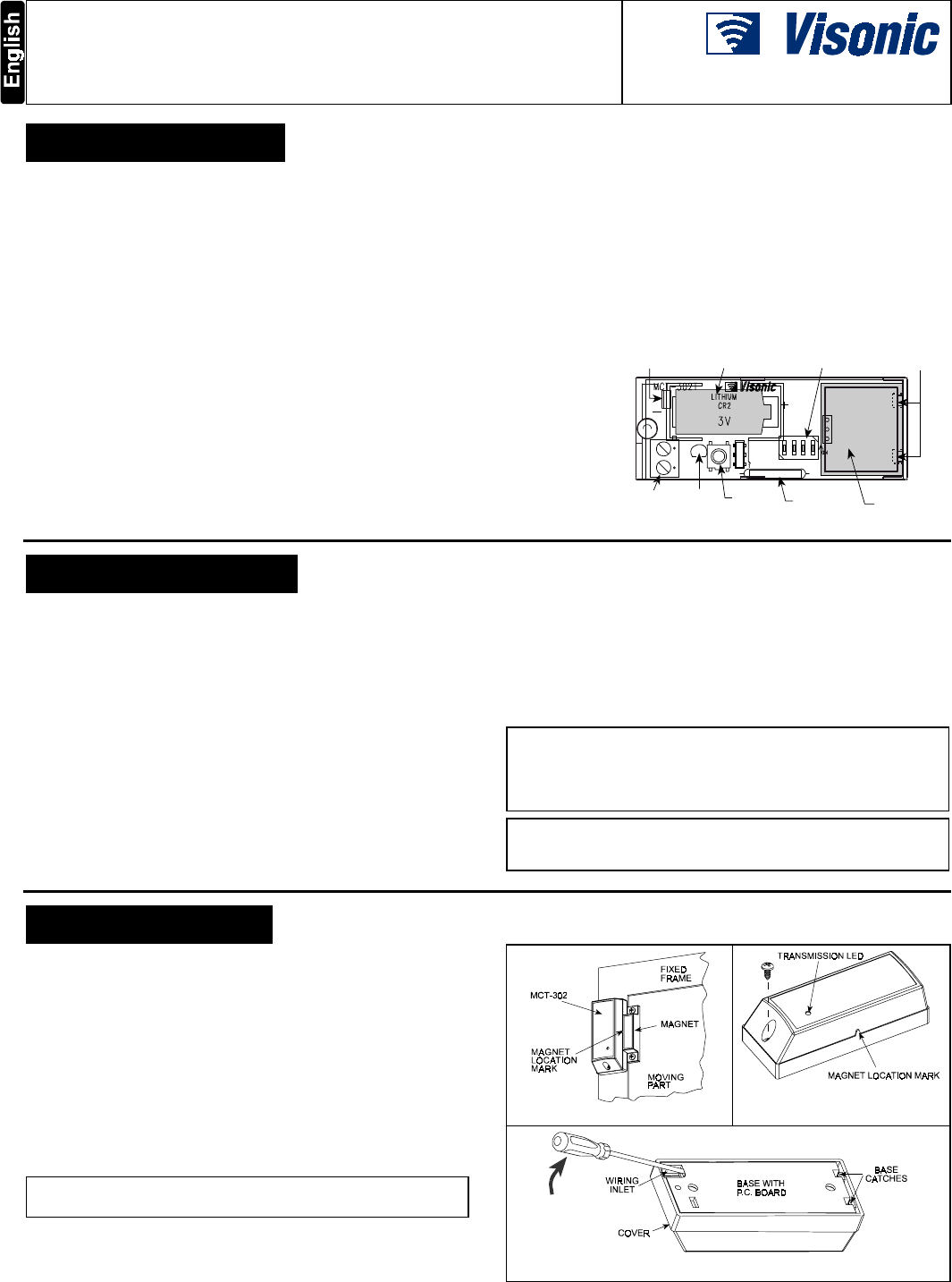
FUNCTION
SELECTOR
TRANSMITTER
RF MODULE
TAMPE R
SWITCH
AUX. INPUT
TERMINALS
3V LITHIUM
BATTERY
REED
SWITCH
LED
FLEXIBLE
RETAINER
P. C . B O A R D
SUPPORTS
NOTE: ONCE THE COVER IS
TAKEN OFF AN ACTIVE MCT-
302 UNIT, A TAMPER MES-
SAGE IS TRANSMITTED TO
THE RECEIVER.
SUBSEQUENT REMOVAL OF
THE BATTERY PREVENTS
TRANSMISSION OF “TAMPER
RESTORE”, LEAVING THE
RECEIVER IN PERMANENT
TAMPER ALERT. TO AVOID
THIS, PRESS THE TAMPER
SWITCH AND MAINTAIN IT
PRESSED WHILE YOU
REMOVE THE BATTERY.
Figure 1. MCT-302 with Cover Removed
2
22
2. SPECIFICATIONS
. SPECIFICATIONS. SPECIFICATIONS
. SPECIFICATIONS
Frequency (MHz): 315, 433.92, 868.95 or other per local
requirements (UL has only investigated at 315 MHz).
Transmitter's ID Code: 24-bit digital word, over 16 million
combinations, pulse width modulation.
Overall Message Length: 36 bits
Alarm Inputs: 2, one internal and one external, with a separate 24-bit
transmitter ID each.
Auxiliary Input Circuit Type: N.C. / E.O.L., selected with DIP switch
E.O.L. Resistor Required: 47 kΩ
Message Repetition: Repetitive transmission (once every 3 minutes)
or one-shot, as selected with on-board DIP switch.
Supervision: Signaling at 60-minute intervals or according to the local
standard from the reed switch (if enabled) or from the aux. input (if the
reed switch is disabled).
Response to Tamper Event: Tamper report every 3 minutes (until
the tamper switch is restored).
Power Source: 3 V Lithium CR-2 type battery, Panasonic or
equivalent.
Battery Life Expectancy: 3 years (for typical use)
Battery Supervision: Automatic transmission of battery condition data
as part of any status report.
Operating Temperature: 0°C to 49°C (32°F to 120°F).
Dimensions: 81 x 22 x 23.5 mm (3-3/16 x 7/8 x 15/16 in.).
Weight: MCT-302 (excluding battery): 34 g (1.2 oz)
Magnet: 13 g (0.45 oz)
Standards: Meets FCC Part 15, MPT1349 and Directive 1999/5/EC
This device complies with Part 15 of the FCC Rules and RSS-210 of
Industry and Science Canada. Operation is subject to the following two
conditions: (1) This device may not cause harmful interference, and (2)
this device must accept any interference received, including
interference that may cause undesired operation.
This device complies with the essential requirements and provisions of
Directive 1999/5/EC of the European Parliament and of the Council of
9 March 1999 on radio and telecommunications terminal equipment.
3
33
3. INSTALLATION
. INSTALLATION. INSTALLATION
. INSTALLATION
3.1 Mounting
It is highly recommended to attach the transmitter to the fixed
frame and the magnet to the movable part (door or window), as
shown in Figure 2. Make sure that the magnet is located not more
than 6 mm (0.25 in.) from the transmitter’s marked side.
A. Remove the case closure screw (Figure 3).
B. Remove the unit’s cover as shown in Figure 4.
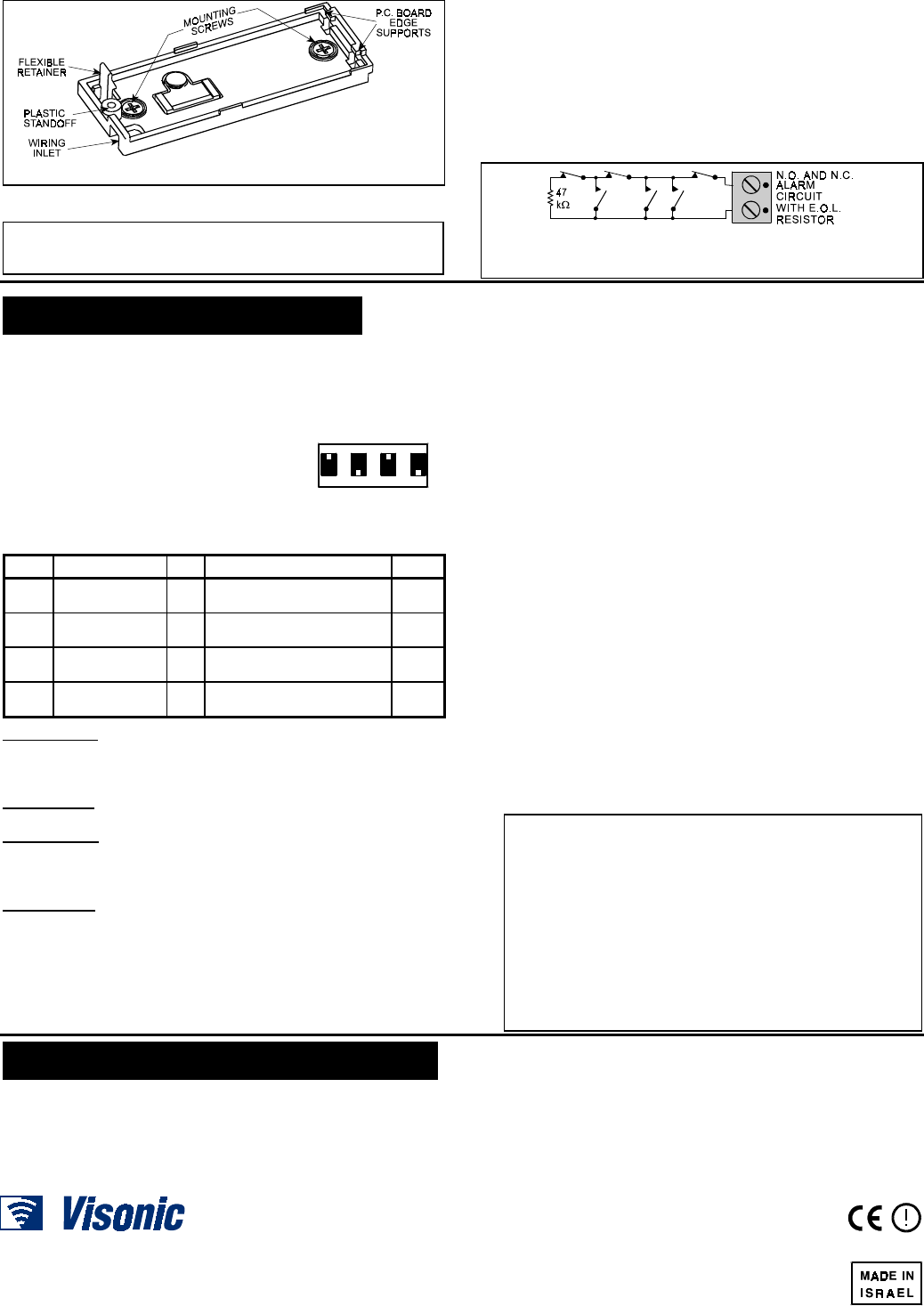
C. Flex out the circuit board retainer (Figures 1 and 5) and
detach the circuit board from the base.
D. Hold the base against the mounting surface and mark the drilling
points through the mounting holes (Figure 5).
E. Drill the holes and fix the base to the wall using the 2 screws with
countersunk heads supplied in the package.
CAUTION! Screws with other type or size of head may short
circuit the bottom side of the printed circuit board.
F. Mount the magnet near the marked side of the MCT-302.
G. Insert the edge of the P.C. board with the RF module into the
edge supports, and press the other edge against the flexible
retainer until it snaps home with a click.
Figure 2. Mounting Example
Figure 3. Removing the
Case Closure Screw
Figure 4. Separating the Cover from the Base
2DE2281U
Figure 5. Base with P.C. Board Removed
3.2 Auxiliary Input Wiring
Remember! If your application does not require the auxiliary input,
be sure to set DIP switch SW2 to OFF and to short the input
terminals together with a piece of jumper wire.
A. Connect the auxiliary detector’s alarm contacts across the
MCT-302 auxiliary input terminals.
B. If the auxiliary input of the MCT-302 is defined as a Normally
Closed (N.C.) type (SW2 set to OFF), series connected N.C.
sensor contacts must be used exclusively. An E.O.L. resistor will
not be required.
C. If the auxiliary input is defined as an E.O.L. type (SW2 set to ON),
Normally Closed (N.C.) as well as Normally Open (N.O.) sensor
contacts can be used. A 47kΩ E.O.L. resistor must be wired at the
far end of the zone loop, as in Figure 6.
Note: An alarm message will be transmitted
once the loop is opened or short circuited
Figure 6. E.O.L. Wiring Example
4
44
4. PREPARATION FOR USE
. PREPARATION FOR USE. PREPARATION FOR USE
. PREPARATION FOR USE
4.1 The Function Switches
A. Switch Tasks
The MCT-302 has a 4-position DIP switch function selector (Figure 7).
Each switch lever allows you to select one of two options.
B. Setting the Switches
Set the function switches as desired prior to
applying power. Use a ball point pen or
another pointed object to shift the switch
levers. The ON position is indicated by
the arrow on the switch body.
ON
1234
Figure 7. Function
Selector
Table 1. Getting acquainted with the function selector
Sw- Function Pos. Selected Option Default
SW1 Reed switch input
enable/disable
ON
OFF
Reed switch input is enabled
Reed switch input is disabled
ON
SW2 Aux. input type
selector
ON
OFF
Aux. input is E.O.L. (47 kΩ)
Aux. input is N.C.
OFF
SW3 Restore reports
enable/disable
ON
OFF
Restore events reported
Restore events not reported
ON
SW4 Transmit mode
selector
ON
OFF
Alarms reported every 3 min.
Alarms reported only once
OFF
SWITCH SW1: Determines whether the reed switch input will be
active or inactive.
Note: With SW1 set to OFF, the reed switch input will not initiate
periodic supervision transmissions.
SWITCH SW2: Determines whether the auxiliary input will behave as
a 47kΩ end-of-line (E.O.L.) input or as a normally closed (N.C.) input.
SWITCH SW3: Determines whether the transmitter will report a
restore event when an input restores from an alarm condition.
Note: Selecting the ON position enables you to find out whether the
door or window under surveillance are open or closed.
SWITCH SW4: In non-supervised systems, it is sometimes required
to report an alarm repeatedly at short intervals, until the disturbed
input reverts to its normal (undisturbed) state. SW4 is used to select
between repetitive and one-shot transmission.
Note: Transmissions initiated by “tamper” events will be repeated
once every 3 minutes, regardless of SW4 setting.
When done, Install the battery as directed in Para. 4.2.
4.2 Testing the Unit
Before testing, set DIP switches SW1 through SW4 as required for
the particular application (Para. 4.1).
A . Insert the battery between the battery clips, at the correct polarity.
For proper operation, only Lithium Thionyl Chloride battery
(Panasonic type CR2 or equivalent) should be used.
B . Press the tamper switch once and release it.
Note: Since the cover is removed and power is applied, a tamper
situation exists. Verify that the MCT-302 transmits (the LED lights
briefly) once every 3 minutes.
C . When you are satisfied that tamper alerts are transmitted
properly, put the cover on to return the tamper switch to its normal
(undisturbed) position. Wait slightly over 3 minutes to verify that
tamper transmissions cease. If all went well, secure the front
cover to the base with the case closure screw.
D . Momentarily open the door or window and verify that the
transmitter LED lights, indicating that transmission is in progress.
If SW4 is ON, wait 3 minutes to verify that the transmission is
repeated at 3-minute intervals.
E . Close the door or window, thus restoring it to the undisturbed
state and watch the LED. If SW3 is set to ON, a “restore”
transmission will now take place.
F . If the auxiliary input is used, momentarily activate the detector
connected to it and check for a response similar to that described
in D above. Then restore the input loop to its undisturbed state.
The response should be as in E above.
G . Refer to the target receiver’s installation instructions, and let the
receiver “learn” the ID codes associated with the reed switch (if
used) and the auxiliary input (if used).
ATTENTION! Each input of the MCT-302 has a different ID. You
must enroll the ID that you are using (if you are using the
internal reed switch, activate the reed switch. If you are using
the AUX input, trigger this input. If you are using both, activate
the reed switch and then trigger the AUX input, or vice versa).
With the target receiver in the LEARN mode, an alarm
transmission from each input will enroll the input’s ID in the
receiver’s memory.
Note Regarding Tamper Message Transmission
- If the reed switch input is enabled (SW1 is ON), the tamper
message will be sent with the reed switch’s ID.
- If the reed switch input is disabled (SW1 is OFF), the tamper
message will be sent with the auxiliary input’s ID.
5
55
5. MISCELLANEOUS COMMENTS
. MISCELLANEOUS COMMENTS. MISCELLANEOUS COMMENTS
. MISCELLANEOUS COMMENTS
Visonic Ltd. wireless systems are very reliable and are tested to high
standards. However, due to low transmitting power and limited range
(required by FCC and other regulatory authorities), there are some
limitations to be considered:
A. Receivers may be blocked by radio signals occurring on or near
their operating frequencies, regardless of the digital code used.
B. A receiver responds only to one transmitted signal at a time.
C. Wireless devices should be tested regularly to determine whether
there are sources of interference and to protect against faults.
The user is cautioned that changes or modifications to the unit,
not expressly approved by Visonic Ltd., could void the user’s
FCC or other authority to operate the equipment.
VISONIC LTD. (ISRAEL): P.O.B 22020 TEL-AVIV 61220 ISRAEL. PHONE: (972-3) 645-6789, FAX: (972-3) 645-6788
VISONIC INC. (U.S.A.): 10 NORTHWOOD DRIVE, BLOOMFIELD CT. 06002-1911. PHONE: (860) 243-0833, (800) 223-0020 FAX: (860) 242-8094
VISONIC LTD. (UK): FRASER ROAD, PRIORY BUSINESS PARK, BEDFORD MK44 3WH. PHONE: (0870) 730-0800 FAX: (0870) 730-0801
INTERNET: www.visonic.com
VISONIC LTD. 2002 MCT-302 (3V) DE2281U- (REV. 1 11/02) Refer to separate warranty statement