Visonic MCT370SMA5 MCT-370 SMA ZigBee Door/Window Contact User Manual
Visonic Ltd. MCT-370 SMA ZigBee Door/Window Contact
Visonic >
User Manual
MCT-370 Installation Instructions
MCT-370 SMA
Door / Window Sensor
Installation Instructions
1. INTRODUCTION
The MCT-370 is a fully supervised, wireless magnetic door / window sensor, for use
with ZigBee enabled home security panels. The sensor includes a built-in reed switch
that opens upon removal of a magnet placed near it.
The MCT-370 tamper switch is activated when the cover is removed.
A periodic supervision message is transmitted automatically. The target receiver is
thus informed, at regular intervals, of the unit’s active participation in the system.
Operating power is obtained from an on-board 3 V Lithium battery. When the battery
voltage is low, a “low battery” message will be sent to the receiver 60 days before
expiration of battery life (for operation in room temperature).
2. SPECIFICATIONS
WIRELESS
Supported Network: ZigBee H.A 1.2
Frequency: 2.4 GHz as per IEEE 802.15.4
Tamper Alert: Reported when a tamper event occurs and in any subsequent
message, until the tamper switch is restored.
ELECTRICAL
Internal Battery: 3V Lithium battery, type CR2. Use Panasonic only.
Nominal Battery Capacity: 850 mAh
Battery Life Expectancy: 5 years (for typical use).
Note: Inability to connect with wireless network, or wireless link quality no higher than
20% may significantly reduce the expected battery life.
Battery Power Test: Performed immediately upon battery insertion and periodically
every several hours.
Battery Supervision: Automatic transmission of battery condition data as part of any
status report.
ENVIRONMENTAL
Operating Temperature: 0C to 50C (32F to 122F)
Humidity: 93% RH, non-condensing
Dimensions: 59.5 x 29 x 11 mm (2-11/32 x 1-9/64 x 7/16 in.)
Weight (including battery): 21.5g (0.8 oz)
3. ACTIVATING AND PAIRING THE SENSOR
To pair the sensor to the security panel, you must set it to pairing mode.
1. Set the panel to pairing mode.
2. To activate pairing mode on the sensor, pull the activation strip from the back of the
sensor (Figure 2).
3. The LED blinks 3 times every 5 seconds (repeated for up to 20 times) to indicate that
the sensor is searching for a security panel.
Note: : If the sensor pairing is not successful during the searching process, restart it
by tripping the reed switch or tamper switch of the door window sensor.
4. Complete the pairing procedure on the security panel. (See the pairing instructions
in the security panel installation guide.)
Note: Pairing should be done before installation.
4. INSTALLATION AND SENSOR TESTING
CAUTION: This equipment shall be installed by Service Personnel in non-
hazardous indoor locations only.
4.1 Mounting
NOTE: It is highly recommended to attach the door / window sensor to the top of the
door / window on the fixed frame and the magnet to the movable part (door or window).
Make sure that the magnet is located not more than 6 mm (0.25 in.) from the sensor’s
marked side.
The sensor should be mounted on the fixed surface and the magnet on the moving
surface (see Figure 3b).
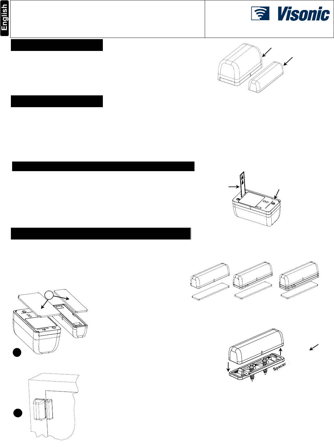
1. Peel away the release liners from the
two strips of double-sided adhesive
tape and attach to the device and
magnet (see Figure 3a).
OR
Secure the device using the screws
provided.
a. Remove the cover by inserting a
screw driver in the opening and
pulling up. (see Figure 2).
b. Attach the mounting plate to the
sensor with the two screws
provided.
c. Place the cover onto the unit
with the mounting plate installed.
Make sure the tabs clear the
cover, and then slide the cover
onto the mounting plate.
2. Align the device with the magnet
according to the location marks and
fasten the device and magnet to the
mounting surface. The sensor should
be mounted on the fixed surface and
magnet on the moving surface (see
Figure 3b).
4.2 Magnet Mounting
The magnet can be mounted with adhesive tape or screws. To mount the magnet with
adhesive tape, it is optional to use one or two spacers (see Figure 4).
To mount the magnet with screws, always use one spacer (see Figure 5).
1. Fasten the spacer to the mounting surface with two screws.
2. Locate the magnet on the spacer at the correct direction and push it
upward.
4.2 Sensor Testing
1. Open and close the door or window and confirm the status is properly updated on
the security panel.
2. Perform the signal strength testing procedure to make sure the device has a good
signal. This procedure is described in the security panel installation manual.
Door / Window Sensor
Magnet
Activation Strip
A
1
2
Magnet
Figure 1 – External View
Figure 2 – Activation Strip
Fig. 5 – Magnet Mounting
Fig. 3b – Mounting on Fixed Surface
A. Double-sided
adhesive tape
Opening to remove cover
Fig. 3a – Attaching the Adhesive
Tape
Fig. 4 – Magnet Mounting with Spacers
2 MCT-370 Installation Instructions
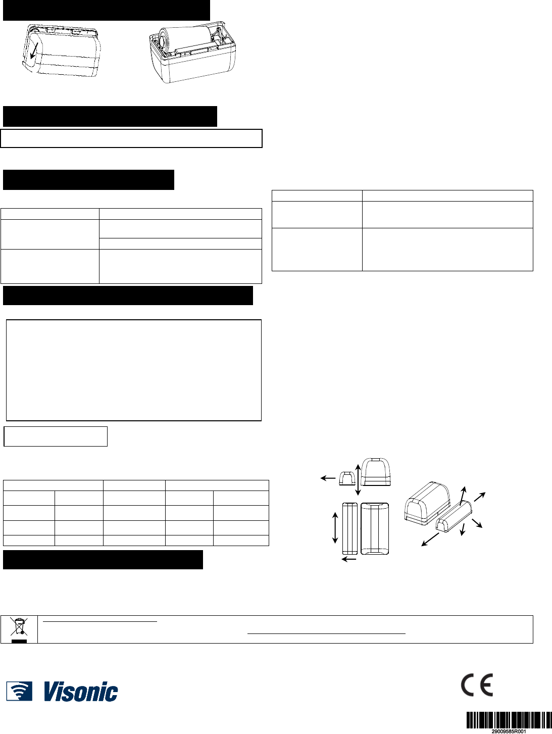
5. BATTERY REPLACEMENT
Fig. 4a – Opening Battery Cover
Fig. 4b –Replacing Battery
1. Press down on the battery cover and slide in the direction shown to open it
(see Figure 4a).
2. Lift the battery from the compartment.
3. Insert the new battery into the sensor while observing battery polarity (see Figure
4b).
4. Close the battery cover.
Note: The required battery is CR2 Lithium 3V, manufactured by Panasonic.
Caution! There is risk of explosion if battery is replaced by an incorrect type. Dispose
of used battery according to the manufacturer's instructions.
6. DEFAULTING THE SENSOR
CAUTION! The defaulting process removes the device from the network and enables
re-pairing.
Open the battery cover and pull back the clip to remove the battery (see Figure 4).
1. Press and hold down the sensor’s tamper switch (see Figure 4b).
2. Insert the battery into the sensor while observing battery polarity (see Figure 4b).
3. Release the tamper switch within 4 seconds. The LED will blink 3 times every 5
seconds to indicate successful default.
4. To re-pair the sensor, follow the instructions in section 3.
7. TROUBLESHOOTING
If you encounter one of the following problems with the MCT-370, do the suggested
remedy:
Problem
Remedy
Attempt to pair the sensor is
unsuccessful.
Make sure that the sensor has been defaulted and is
set to pairing mode (see section 7).
Make sure the security panel supports the MCT-370.
The sensor and the panel do
not communicate.
Perform the signal strength testing procedure
described in the security panel installation manual.
Make sure that the signal is sufficient. If necessary,
replace the sensor’s battery.
Problem
Remedy
The sensor sends a Low
Battery indication.
To ensure continuous proper operation, replace the
battery within two weeks of the first Low Battery
indication (see section 5).
Panel does not arm because
of an unrecognized sensor
malfunction
Consult with your installer or system provider
before you disable a zone.
Disable the detector zone (see the security panel user
manual). Note that disabling a sensor zone lowers the
overall security level of your system.
8. COMPLIANCE WITH STANDARDS
USA/CANADA
FCC USA: CFR 47 part 15, Canada: RSS 247.
This device complies with Part 15 of the FCC Rules and RSS-247 of Industry and
Science Canada. Operation is subject to the following two conditions: (1) This device
may not cause harmful interference, and (2) this device must accept any interference
received, including interference that may cause undesired operation.
This device complies with Industry Canada license-exempt RSS standard(s). Operation is
subject to the following two conditions: (1) this device may not cause interference, and (2)
this device must accept any interference, including interference that may cause undesired
operation of the device.
Le présent appareil est conforme aux CNR d'Industrie Canada applicables aux
appareils radio exempts de licence. L'exploitation est autorisée aux deux conditions
suivantes : (1) l'appareil ne doit pas produire de brouillage, et (2) l'utilisateur de
l'appareil doit accepter tout brouillage radioélectrique subi, même si le brouillage est
susceptible d'en compromettre le fonctionnement.
FCC ID: WP3MCT370SMA5
IC: 1467C-MCT370SMA
USA/CANADA
Complies with:
ANSI/UL 634, ULC/ORD – C634
FCC Compliance Statement
This device has been tested and found to comply with the limits for a Class B digital
device, pursuant to Part 15 of the FCC Rules. These limits are designed to provide
reasonable protection against harmful interference in residential installations. This
equipment generates uses and can radiate radio frequency energy and, if not
installed and used in accordance with the instructions, may cause harmful
interference to radio and television reception.
However, there is no guarantee that interference will not occur in a particular
installation. If this device does cause such interference, which can be verified by
turning the device off and on, the user is encouraged to eliminate the interference by
one or more of the following measures:
– Re-orient or re-locate the receiving antenna.
– Increase the distance between the device and the receiver.
– Connect the device to an outlet on a circuit different from the one that supplies
power to the receiver.
– Consult the dealer or an experienced radio/TV technician.
WARNING! Changes or modifications to this unit not expressly approved by the party
responsible for compliance could void the user’s authority to operate the equipment.
Reed Switch Positions
Note: Dimensions in the following table are typical.
Wood
Supports
Iron
Opening
Closing
Direction
Opening
Closing
15 mm
14 mm
X
13 mm
12 mm
29 mm
24 mm
Y
11 mm
8 mm
37 mm
31 mm
Z
11 mm
8 mm
9. PRODUCT LIMITATIONS
Visonic Ltd. wireless systems are very reliable and are tested to high standards. However,
due to low transmitting power and limited range (required by FCC and other regulatory
authorities), there are some limitations to be considered:
A. Receivers may be blocked by radio signals occurring on or near their operating
frequencies, regardless of the digital code used.
B. A receiver responds only to one transmitted signal at a time.
C. Wireless devices should be tested regularly to determine whether there are sources of
interference and to protect against faults.
The user is cautioned that changes or modifications to the unit, not expressly
approved by Visonic Ltd., could void the user’s FCC or other authority to operate the
equipment.
W.E.E.E. Product Recycling Declaration
For information regarding the recycling of this product you must contact the company from which you orignially purchased it. If you are discarding this product and not returning it for
repair then you must ensure that it is returned as identified by your supplier. This product is not to be thrown away with everyday waste.
Directive 2002/96/EC Waste Electrical and Electronic Equipment.
This device complies with the essential requirements and provisions of Directive 1999/5/EC of the European Parliament and of the Council of 9 March 1999 on radio and telecommunications
terminal equipment.
EMAIL: info@visonic.com
INTERNET: www.visonic.com
VISONIC LTD. 2016 MCT-370 (Rev 1, 1/16) Please refer to the separate Warranty statement
Y
Z
Z
Figure 5 - Range Coverage Directions
X
Y
X
X
Y
Z
RF Exposure Information
This equipment complies with FCC and Industry Canada radiation exposure limits set forth
for an uncontrolled environment. In order to avoid the possibility of exceeding the FCC and
IC radio frequency exposure limits, human proximity to the antenna shall not be less
than 20cm during normal operation.