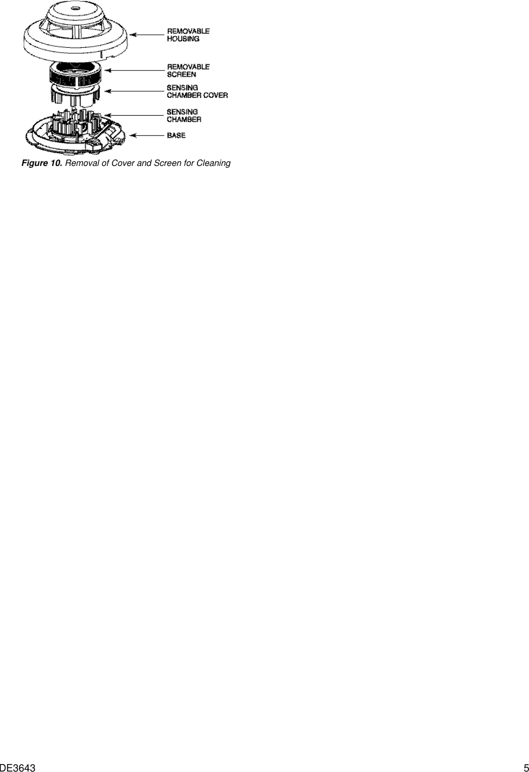
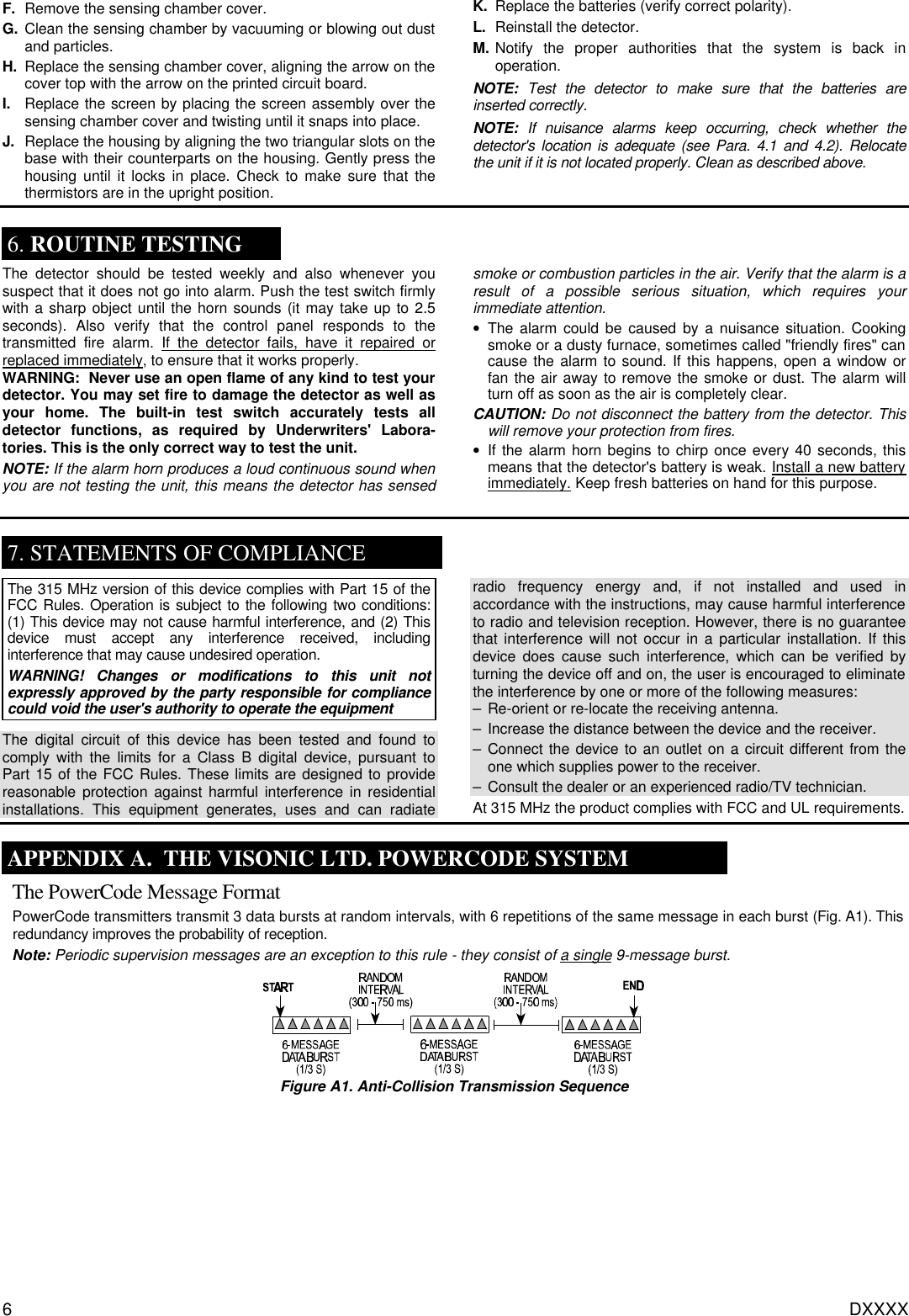
Visonic MCT430 Photoelectric Smoke Detector User Manual Instr

Visonic Inc. Photoelectric Smoke Detector Instr

Users Manual

DE3643 1 MCT-430 Supervised Wireless PowerCode Smoke Detector  Installation Instructions   1. INSTALLATION SUMMARY 1.1 General Description  The MCT-430 is a low profile, battery operated, photoelectric smoke detector which shares its housing with a UHF PowerCode type transmitter. It has a 57°C (135°F) fixed temperature heat detector and a built-in sounder. The detector sends out the following messages to the control panel: • Smoke alarm • Heat alarm • Tamper alert • Low battery alert • Trouble message (when heat sensor malfunctions) • Service alert (degraded smoke detection sensitivity - internal screen requires cleaning). During normal and low battery conditions, the LED flashes approximately once every 40 seconds. The smoke/heat detector will sound its built-in temporal horn when smoke activates the detector (the LED flashes rapidly), or when the air temperature reaches 57°C (135°F). A message is also sent to the wireless control panel. After the horn stops, a RESTORE message is transmitted to the control panel and the ID number can be cleared from the panel. The built-in Drift Compensation algorithm automatically maintains the sensitivity of the detector. Once the detector reaches its limit of compensation, it transmits a maintenance signal to the panel. When maintenance is required, the LED stops flashing. The maintenance signal fully complies with the sensitivity test requirement specified in NFPA 72, 7 - 2.2.  Figure 1. General View 1.2 Power Up and Initial Test The smoke detector is supplied with two 3V batteries seated within their holder but insulated from the battery terminals.  A. Turn the detector upside down and pull out the paper tab that insulates the batteries from one of the terminals.  B. Insert a sharp object into the test switch hole and push the switch in continuously, until the built-in horn sounds (about 2.5 seconds after depressing the button). The sounding sequence is: 3 beeps - short break - 3 beeps ......and so on until you release the switch. In addition, the LED will flash rapidly a few times. This means that the smoke detection section is working properly. 1.3 Enrolling Transmitter’s Power- Code ID The detector includes a tamper switch that causes a tamper alert when the main body is separated from its mounting bracket. This switch protects the unit against unauthorized handling.  The detector has two separate PowerCode IDs: • The first ID is linked to messages containing alarm, low battery and supervision data. • The second ID is linked to messages containing tamper and maintenance data such as “clean” and circuit trouble. Enrolling process to the PowerMax is differennt from the enrolling process to other versions of the PowerMax (PowerMax+, PowerMax GSM....), as described in par. 1.3.1 and 1.3.2. 1.3.1 Enrolling to PowerMax Control Panel It is necessary that the control panel will learn the two IDs before the detector is actually mounted in place. This is best carried out in close proximity to the control panel. Each ID must be enrolled to a separate zone of the control panel.  A. Refer to the control panel’s installation instructions and follow the procedure given there for enrolling transmitter IDs in the control panel's memory.  2nd. When required to initiate a transmission for enrollment of the first ID, activate the test switch (see fig. 1) until the built-in horn sounds (see Para. 1.2B).  C. When you are instructed to initiate a transmission for enrollment of the second ID, separate the detector from the bracket to activate a tamper message.   Important: If the second ID is not learnt by the control panel, the maintenance and tamper messages will not be received. Note:  The PowerMax control panel can not distinguish  between “clean” and circuit trouble data. Upon receiving a maintenance alert, clean the internal screen as described in Para. 5.2. If the maintenance alert persists, the trouble is probably due to a circuit failure.  1.3.2 Enrolling to Other Versions of PowerMax (PowerMax+, PowerMax GSM...) To enroll the transmitters IDs to the PowerMax+, PowerMax GSM and above,  it is necessary to enrol only one ID, the first ID or the second ID (for IDs description refer to par. 1.3). When either ID is enrolled to one zone, the second ID is automatically enrolled. The enrolling process is as follows: A. Refer to the control panel’s installation instructions and follow the procedure given there for enrolling transmitter IDs in the control panel's memory.  2nd. When you are instructed to initiate a transmission for enrollment of the ID, activate the test switch until the built-in horn sounds (see Para. 1.2B), or separate the detector from the bracket to activate a tamper message.   1.4 Mounting the Bracket in Place Read Section 4 in this manual first, then decide where to install the detector. Refer to Figure 2 and proceed according to the following instructions.
2 DE3643  Figure 2. Mounting Bracket 1st.If the detector is attached to the bracket, separate it from the bracket by holding the bracket in one hand and turning the detector slightly counterclockwise with your other hand. Note: Removal of the unit from the bracket will initiate a tamper alert! The LED will flash but the horn will remain silent. 2nd.Press the bracket against the mounting surface and mark the drilling spots through two mounting screw bays.  C. Drill two 5 mm (3/16”) holes at the marked spots. D. Attach the bracket to the wall, using the two screws and plastic wall anchors (supplied). 1.5 Assembly and Test A. Align the marks on the detector’s body with the arrows on the bracket. Push the detector against the bracket and turn it slightly clockwise until it snaps into place. Pull outward to make sure that the detector is securely attached to the bracket. B. Press the test button until the built-in horn sounds. Verify that the transmitted signal has been received at the control panel, and that the control panel responds accordingly by activating the fire alarm siren or any other warning device.  2. MISCELLANEOUS WARNINGS WARNING: This smoke detector is designed for use in a single residential unit only, which means that it should be used inside a single family home or apartment. It is not meant to be used in lobbies, hallways, basements or another apartment in multi-family buildings, unless there are already working detectors in each family unit. Smoke detectors, placed in common areas outside the individual living unit, such as on porches or in hallways, may not provide early warning to residents. In multi-family buildings, each family living unit should set up its own detector. WARNING: This detector is not meant to be used in non- residential buildings. Warehouses, industrial or commercial buildings and special purpose non-residential buildings require special fire detection and alarm systems. This detector alone is not a suitable substitute for complete fire detection systems for places where many people live or work, such as hotels or motels. The same is true of dormitories, hospitals, nursing homes or group homes of any kind, even if they were once single family homes. Please refer to NFPA 101, the Life Safety Code, NFPA71, 72A, 72B, 72C, 72D and 72E for smoke detector requirements for fire protection in buildings not defined as "households". WARNING: This detector, if used as a stand-alone unit, will not alert people who are hard of hearing.   3. SPECIFICATIONS SMOKE AND HEAT DETECTION Activity Indicator: LED flashes once per 40 sec. Nominal Smoke Detection Sensitivity: 2.25% per foot obscuration Heat Detection: Alarm if ambient temperature exceeds 57°C (135°F) Alarm Sound Level: 85 dB min at 3 m (10 ft) at minimum battery voltage TRANSMITTER AND CODING Operating Frequency (MHz): 315 Transmitter's ID Code: 24-bit digital word, over 16 million combinations, pulse width modulation. Overall Message Length: 36 bits Supervision: Automatic signaling at 60-minute intervals. Tamper Alerts: Tamper event (removal of the unit from its bracket) is reported once. Tamper restore is also reported once. Compliance with standards: Designed to meet FCC part 15, MPT 1340 UL 268 recognized component. ELECTRICAL DATA Power Source: Two CR123A lithium batteries in series (6 VDC nominal). Operating Voltage Range:  4.8 - 6.5 VDC Current Drain: 14.5 µA standby (typical), 20 mA typical in operation Battery Life (at room temperature): 3 years typical Battery Supervision: Once every 60 minutes; automatic transmission of battery status data as part of any transmitted message. PHYSICAL DATA Operating Temperature:  0°C to 38°C (32°F to 100°F) Relative Humidity: 10% to 93%, non-condensing Dimensions: 140 mm (5.5") diameter with bracket x 52 mm (2.05") Weight (with batteries): 218 g (7 oz)     4. SMOKE DETECTOR INSTALLATION OVERVIEW 4.1 Where to Install Smoke Detectors Smoke detectors should be installed in accordance with the NFPA (National Fire Protection Association, Batterymarch Park, MA 02269-9101) Standard 72. For complete coverage in residential units, smoke detectors should be installed in all rooms, halls, storage areas, basements and attics in each family living unit. Minimum coverage is one detector on each floor and one in each sleeping area. Here are a few useful tips for you: • Install a smoke detector in the hallway outside every separate bedroom area, as in Figure 3. Two detectors are required in homes with two bedroom areas, as in Figure 4. • Install a smoke detector on every floor of a multi-floor home or apartment, as shown in Figure 5. • Install a minimum of two detectors in any household. • Install a smoke detector inside every bedroom. • Install smoke detectors at both ends of a bedroom hallway if the hallway is more than 12 meters (40 feet) long. • Install a smoke detector inside every room where one sleeps with the door partly or completely closed, since smoke could be blocked by the closed door and a hallway alarm may not wake up the sleeper if the door is closed.
DE3643 3  Figure 3. Placement of a Smoke/Heat Detector in a Single-Floor Residence with Only One Sleeping Area  Figure 4. Placement of Smoke/Heat Detectors in Single-Floor Residence with More than One Sleeping Area  Figure 5. Placing Smoke/Heat Detectors in a Multi-Floor Residence • Install basement detectors at the bottom of the basement stairwell, as shown in Figure 5. • Install second-floor detectors at the top of the first-to-second floor stairwell. • Be sure no door or other obstruction blocks the path of smoke to the detector. • Install additional detectors in your living room, dining room, family room, attic, utility and storage rooms. • Install smoke detectors as close to the center of the ceiling as possible. If this is not practical, put the detector on the ceiling, at least 10 cm (4 inches) away from any wall or corner, as shown in Figure 6. • If ceiling mounting is not possible and wall mounting is permitted by your local and state codes, put wall-mounted detectors between 10 - 15 cm (4 - 6 inches) from the ceiling, also shown in Figure 6. • If some of your rooms have sloped, peaked, or gabled ceilings, try to mount detectors 0.9 meter (3 feet) measured horizontally from the highest point of the ceiling, as shown in Figure 7.  Figure 6. Recommended Best  and Acceptable Locations to  Mount Smoke Detectors   Figure 7. Recommended  Location to Mount Smoke  Detectors in Rooms with Sloped, Gabled or Peaked Ceilings  CAUTION (As required by California State Fire Marshall) "Early warning fire detection is best achieved by the installation of fire detection equipment in all rooms and areas of the household as follows: (1) A smoke detector installed in each separate sleeping area (in the vicinity, but outside the bedrooms), and (2) Heat or smoke detectors in the living rooms, dining rooms, bedrooms, kitchens, hallways, attics, furnace rooms, closets, utility and storage rooms, basements and attached garages." For your information, NFPA Standard 72, Section 2-2.1.1.1 reads as follows: "Smoke detectors shall be installed outside each separate sleeping area in the immediate vicinity of the bedrooms and on each additional story of the family living unit including basements and excluding crawl spaces and unfinished attics. In new construction, a smoke detector also shall be installed in each sleeping room." The above NFPA standard is a minimum requirement for smoke detector installation. For better protection, we also require the installation of a smoke detector inside every bedroom in existing construction. 4.2 Where Not to Install Smoke Detectors False alarms occur when smoke detectors are installed where they will not work properly. To avoid false alarms, do not install smoke detectors in the following situations: • In or near areas where combustion particles are normally present such as kitchens; in garages where there are particles of combustion in vehicle exhausts; near furnaces, hot water heaters, or gas space heaters. Install detectors at least 20 feet (6 meters) away from kitchens and other areas where combustion particles are normally present.  • On the ceiling in rooms next to kitchens where there is no transom between the kitchen and these rooms. Instead, install the smoke detector on an inside wall, furthest from the kitchen. Be sure not to install smoke detectors within 4" of the ceiling or any corner or more than 6" from the ceiling. • In damp or very humid areas, or next to bathrooms with showers. • The moisture in humid air can enter the sensing chamber as water vapor, then cool and condense into droplets that cause a nuisance alarm. Install detectors at least 5 feet (1.5 meters) away from bathrooms. • In very cold or very hot rooms or areas. Operating temperature of the smoke detector is 40°F to 100°F (4°C to 38°C). • In dusty, dirty, or insect-infested areas. Dust and dirt can build up on the detector’s sensing chamber and make it overly sensitive, or can block openings to the sensing chamber and keep the detector from sensing smoke. • Near fresh air inlets or returns or excessively drafty areas. Air conditioners, heaters, fans, and fresh air intakes and returns can drive smoke away from smoke detectors, making the detectors less effective. • In dead air spaces at the top of a peaked ceiling or wall/ceiling intersect. Dead air may prevent smoke from reaching a detector.  • Near fluorescent light fixtures. Install detectors at least 10 feet (3 meters) away from such light fixtures.  Figure 8. Recommended Smoke Detector Locations to Avoid Air Streams with Combustion Particles
4 DE3643 WARNING: Never remove batteries to stop a nuisance alarm. Open a window or fan the air around the detector to get rid of the smoke. The alarm will turn itself off when the smoke is gone. If nuisance alarms persist, attempt to clean the detector as described in this manual.  WARNING: Do not stand close to the detector when the alarm is sounding. The alarm is loud in order to wake you in an emergency. Too much exposure to the horn at close range may be harmful to your hearing. 4.3 Smoke Detector Limitations • Smoke detectors will not sense a fire if the smoke does not reach the sensor or if the air temperature does not reach 57°C (135°F). In order for a smoke detector to sense smoke, it must be installed in the immediate vicinity of the fire. In addition, smoke from fires in chimneys, in walls, on roofs, in remote parts of the building, or on another level from where the smoke detector is located, may not reach the smoke detector quickly enough for occupants to escape unharmed. For this reason, the installer shall install smoke detectors on every level, in every sleeping area, and in every bedroom of the household. • Smoke detectors may not be heard. The alarm horn in this smoke detector meets or exceeds current Underwriter’s Laboratories standards. However, if the smoke detector is not located in the same room as the occupant, or if it is blocked by a closed door or normal noise, the alarm horn may not be heard. In addition, sound sleepers, or persons who are under the influence of drugs or alcohol may not hear the alarm or be able to react to it. Therefore, locate this smoke detector, which has a sounder rated at 85 dB at 10 feet, on every level, in every sleeping area, and in every bedroom of the household.  • In general, detectors may not always warn you about fires caused by carelessness and safety hazards like smoking in bed, violent explosions, escaping gas, improper storage of flammable materials, overloaded electrical circuits, children playing with matches, or arson.  • Smoke detectors are not fool-proof.  Like all electronic devices, smoke detectors have limitations. No type of smoke detector can sense every kind of fire every time. In addition,  smoke from slow, smoldering fires rises slowly and may not reach the smoke detector until actual flame breaks out. This type of smoke may not reach the smoke detector in time for occupants to escape unharmed. • Smoke detectors are not a substitute for life or property insurance. Though smoke detectors have been responsible for saving many lives, they are not warranted or implied to protect lives or property in the event of a fire. • To keep your equipment in excellent working order, ongoing maintenance is required per the manufacturer’s recommen- dations and UL and NFPA standards. At a minimum, the requirements of Chapter 7 of NFPA 72, The National Fire Alarm Code, shall be followed. A preventative maintenance agreement should be arranged through the local manufac- turer’s representative. Though smoke detectors are designed for long life, they may fail at any time. Any smoke detector, fire alarm equipment, or any component of that system which fails shall be repaired or replaced as soon as possible.    5. MAINTENANCE 5.1 Battery Replacement   The detector checks for low batteries at least every 60 minutes. If the batteries are low, the transmitter sends a low battery message to the control panel. This condition will exist for a minimum of seven days, and then the detector's horn will "chirp" about every 40 seconds. The batteries should be replaced before the chirps begin. Be sure to replace both batteries with fresh ones. To replace batteries: A. Remove the detector from its bracket by twisting the detector counterclockwise, remove batteries, and dispose properly. B.  Install two new 3-volt CR123A lithium batteries in the battery compartment. Follow the polarity diagram inside the compartment. C.  Reinstall the smoke detector onto the bracket by turning the detector clockwise. D.  Test the detector as described in Para. 1.2 of this manual. The LED should flash about once every 40 seconds to indicate normal operation. If the batteries are not installed correctly, the smoke detector will not operate and the batteries may be damaged. If the detector does not appear to be sending a signal during any of the tests, check for correct battery installation. 5.2 Cleaning Before removing the detector, notify the proper authorities that the smoke detector system is undergoing maintenance and will be temporarily out of service. Disable the zone or system undergoing maintenance to prevent unwanted alarms. Before removing the detector cover, note the position of the thermistors (see Figure 1). Make sure the thermistors are not bent over when the housing is replaced. Refer to Figure 9 and proceed as follows: A. Grasp the detector’s body with your hands, rotate it slightly counterclockwise and pull it off the wall-mounted bracket. B. Remove the batteries at the bottom. C. Remove the detector housing by gently prying the four housing tabs on the bottom of the base with a small-bladed screwdriver and pull the housing from the base. Use caution to avoid damaging the thermistors.  D. Vacuum the screen carefully without removing it. E. Remove the screen assembly, pulling straight out (see Fig. 10).  Figure 9. Housing Removal
DE3643 5  Figure 10. Removal of Cover and Screen for Cleaning
6 DXXXX F. Remove the sensing chamber cover. G.  Clean the sensing chamber by vacuuming or blowing out dust and particles. H. Replace the sensing chamber cover, aligning the arrow on the cover top with the arrow on the printed circuit board. I. Replace the screen by placing the screen assembly over the sensing chamber cover and twisting until it snaps into place. J. Replace the housing by aligning the two triangular slots on the base with their counterparts on the housing. Gently press the housing until it locks in place. Check to make sure that the thermistors are in the upright position. K. Replace the batteries (verify correct polarity). L. Reinstall the detector. M. Notify the proper authorities that the system is back in operation. NOTE: Test the detector to make sure that the batteries are inserted correctly. NOTE: If nuisance alarms keep occurring, check whether the detector's location is adequate (see Para. 4.1 and 4.2). Relocate the unit if it is not located properly. Clean as described above.  6. ROUTINE TESTING The detector should be tested weekly and also whenever you suspect that it does not go into alarm. Push the test switch firmly with a sharp object until the horn sounds (it may take up to 2.5 seconds). Also verify that the control panel responds to the transmitted fire alarm. If the detector fails, have it repaired or replaced immediately, to ensure that it works properly. WARNING:  Never use an open flame of any kind to test your detector. You may set fire to damage the detector as well as your home. The built-in test switch accurately tests all detector functions, as required by Underwriters' Labora- tories. This is the only correct way to test the unit.  NOTE: If the alarm horn produces a loud continuous sound when you are not testing the unit, this means the detector has sensed smoke or combustion particles in the air. Verify that the alarm is a result of a possible serious situation, which requires your immediate attention.  • The alarm could be caused by a nuisance situation. Cooking smoke or a dusty furnace, sometimes called "friendly fires" can cause the alarm to sound. If this happens, open a window or fan the air away to remove the smoke or dust. The alarm will turn off as soon as the air is completely clear. CAUTION: Do not disconnect the battery from the detector. This will remove your protection from fires. • If the alarm horn begins to chirp once every 40 seconds, this means that the detector's battery is weak. Install a new battery immediately. Keep fresh batteries on hand for this purpose.   7. STATEMENTS OF COMPLIANCE The 315 MHz version of this device complies with Part 15 of the FCC Rules. Operation is subject to the following two conditions: (1) This device may not cause harmful interference, and (2) This device must accept any interference received, including interference that may cause undesired operation. WARNING! Changes or modifications to this unit not expressly approved by the party responsible for compliance could void the user's authority to operate the equipment The digital circuit of this device has been tested and found to comply with the limits for a Class B digital device, pursuant to Part 15 of the FCC Rules. These limits are designed to provide reasonable protection against harmful interference in residential installations. This equipment generates, uses and can radiate radio frequency energy and, if not installed and used in accordance with the instructions, may cause harmful interference to radio and television reception. However, there is no guarantee that interference will not occur in a particular installation. If this device does cause such interference, which can be verified by turning the device off and on, the user is encouraged to eliminate the interference by one or more of the following measures: – Re-orient or re-locate the receiving antenna. – Increase the distance between the device and the receiver. – Connect the device to an outlet on a circuit different from the one which supplies power to the receiver. – Consult the dealer or an experienced radio/TV technician. At 315 MHz the product complies with FCC and UL requirements.  APPENDIX A.  THE VISONIC LTD. POWERCODE SYSTEM The PowerCode Message Format PowerCode transmitters transmit 3 data bursts at random intervals, with 6 repetitions of the same message in each burst (Fig. A1). This redundancy improves the probability of reception.  Note: Periodic supervision messages are an exception to this rule - they consist of a single 9-message burst.  Figure A1. Anti-Collision Transmission Sequence
DE3640 7    WARRANTY  Visonic Ltd. and/or its subsidiaries and its affiliates ("the Manufacturer") warrants its products hereinafter referred to as "the Product" or "Products" to be in conformance with its own plans and specifications and to be free of defects in materials and workmanship under normal use and service for a period of twelve months from the date of shipment by the Manufacturer.  The Manufacturer's obligations shall be limited within the warranty period, at its option, to repair or replace the product or any part thereof. The Manufacturer shall not be responsible for dismantling and/or reinstallation charges. To exercise the warranty the product must be returned to the Manufacturer freight prepaid and insured. This warranty does not apply in the following cases: improper installation, misuse, failure to follow installation and operating instructions, alteration, abuse, accident or tampering, and repair by anyone other than the Manufacturer. This warranty is exclusive and expressly in lieu of all other warranties, obligations or liabilities, whether written, oral, express or implied, including any warranty of merchantability or fitness for a particular purpose, or otherwise.  In no case shall the Manufacturer be liable to anyone for any consequential or incidental damages for breach of this warranty or any other warranties whatsoever, as aforesaid. This warranty shall not be modified, varied or extended, and the Manufacturer does not authorize any person to act on its behalf in the modification, variation or extension of this warranty. This warranty shall apply to the Product only.  All products, accessories or attachments of others used in conjunction with the Product, including  batteries, shall be covered solely by their own warranty, if any.  The Manufacturer shall not be liable for any damage or loss whatsoever, whether directly, indirectly, incidentally, consequentially or otherwise, caused by the malfunction of the Product due to products, accessories, or attachments of others, including batteries, used in conjunction with the Products. The Manufacturer does not represent that its Product may not be compromised and/or circumvented, or that the Product will prevent any death, personal and/or bodily injury and/or damage to property resulting from burglary, robbery, fire or otherwise, or that the Product will in all cases provide adequate warning or protection. User understands that a properly installed and maintained alarm may only reduce the risk of events such as burglary, robbery, and fire without warning, but it is not insurance or a guarantee that such will not occur or that there will be no death, personal damage and/or damage to property as a result. The Manufacturer shall have no liability for any death, personal and/or bodily injury and/or damage to property or other loss whether direct, indirect, incidental, consequential or otherwise, based on a claim that the Product failed to function.  However, if the Manufacturer is held liable, whether directly or indirectly, for any loss or damage arising under this limited warranty or otherwise, regardless of cause or origin, the Manufacturer's maximum liability shall not in any case exceed the purchase price of the Product, which shall be fixed as liquidated damages and not as a penalty, and shall be the complete and exclusive remedy against the Manufacturer. Warning: The user should follow the installation and operation instructions and among other things test the Product and the whole system at least once a week.  For various reasons, including, but not limited to, changes in environmental conditions, electric or electronic disruptions and tampering, the Product may not perform as expected.  The user is advised to take all necessary precautions for his/her safety and the protection of his/her property. 6/91                                                    VISONIC LTD. (ISRAEL):  P.O.B 22020 TEL-AVIV 61220 ISRAEL. PHONE: (972-3) 645-6789, FAX: (972-3) 645-6788 VISONIC INC. (U.S.A.):  10 NORTHWOOD DRIVE, BLOOMFIELD CT. 06002-1911. PHONE: (860) 243-0833, (800) 223-0020 FAX: (860) 242-8094 VISONIC LTD. (UK):  FRASER ROAD, PRIORY BUSINESS PARK, BEDFORD MK44 3WH. PHONE: (0870) 730-0800 FAX: (0870) 730-0801
8 DE3643 INTERNET:    www.visonic.com VISONIC LTD. 2002       MCT-430       DE3643- (REV. 0, 10/02)

Navigation menu