Visonic MKP150 2-Way Wireless Keypad User Manual MKP 150 for Arik
Visonic Inc. 2-Way Wireless Keypad MKP 150 for Arik
UserManual.wiki
>
Visonic
>
MKP150 User Manual
Users Manual
Navigation menu
Upload a User Manual
Namespaces
Wiki Guide
HTML
PDF
Info
Views
User Manual
Discussion / Help
Navigation
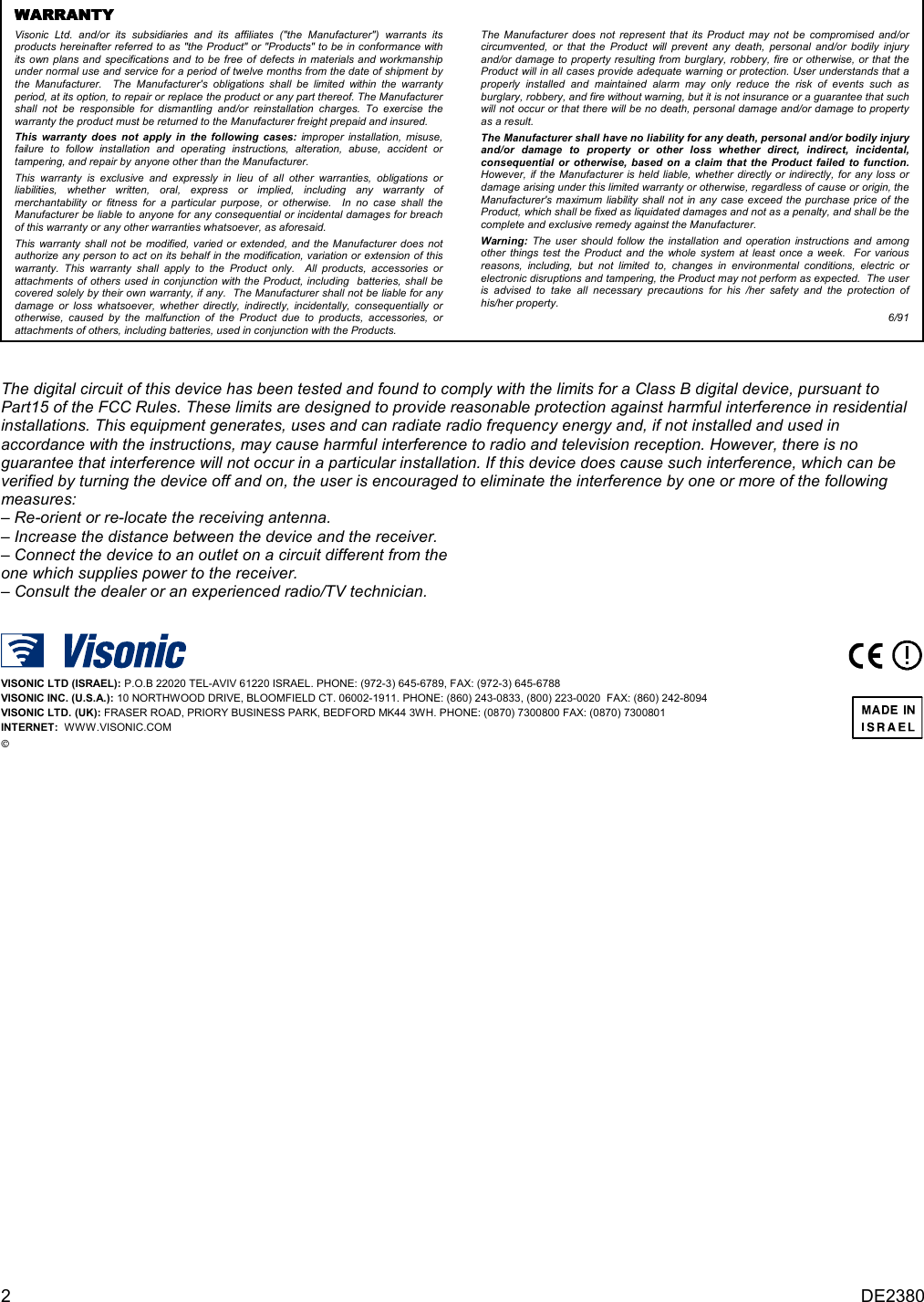
![DE2462U 3 9VACWiringChannelsConnect the 9 VACpower supply to theterminal block. Routethe wiring through thewiring channels.Note: The powersupply is optional Figure 6: Wiring 4. ENROLLING/DELETING THE MKP-150 FROM THE POWERMAX+ MEMORY To enroll all the MKP-150 functions (for complete list see PowerMax+ Installer Guide), enter the PowerMax+ Installer Mode from the PowerMax+ keypad, and proceed as shown in the following illustration. Note: Refer to PowerMax+Installer Guide for details onperforming a diagnostic testOK(First display is READYor NOT READY)READY 00:00USER SETTINGSNORMAL MODEENTER CODE1. NEW INSTL CODE2. ENROLLING[installer code]INSTALLER MODEENROL WL 2WAY KPENROLL WL DEVICEENROLLING TYPE[MKP-150 No. 1 to 2](e.g. 2)2way kp No :2way kp No : 2 2way kp No : 22way kp No: 2Enrolling a wirelessKeypad MKP-150 for next enrolling action<OFF> TO DELETEpress backtamperswitchonce(see Fig. 4)TRANSMIT NOWDeleting a wirelessKeypad MKP-1502way kp No: 2ENROLL KEYFOBBlack rectangle meansthat the MKP-150 No. 2 is already enrolled.AWAYOKNEXTNEXTNEXTNEXTOKOKOKNEXTOKNEXT NEXT NEXTENROL WL 1WAY KP NEXT9. DIAGNOSTICSNEXT Figure 7: Enrolling / Deleting a MKP-150 Device from PowerMax+ Memory 5. DEFINING MKP-150 PARAMETERS5.1 Installer Menu Functions Important: All installer settings affect only the specific keypad on which the settings were performed. The Installer menu enables you to perform three separate functions, as follows: SUPERVISION The keypad transmits supervision reports periodically to the PowerMax+. The options are: 15 minutes, 1 hour and disable. PIEZO BEEP Here you determine whether warning beeps will sound or muted during exit and entry delays. Options: enable beeps, off when home and disable beeps. RECORD SPEECH This mode allows you to record up to 5 custom zone names. SERIAL NUMBER Enables reading the system serial number for support purposes only. 5.1.1 To Set Supervision Time Make sure the system is not in Arm mode. The installer’s menu is accessible only to those who know the installer’s code, which is 9Î9Î9Î9 by factory default. A. Press the next button (►) repeatedly until the display reads: INSTALLER MODE](https://usermanual.wiki/Visonic/MKP150/User-Guide-585821-Page-3.png)
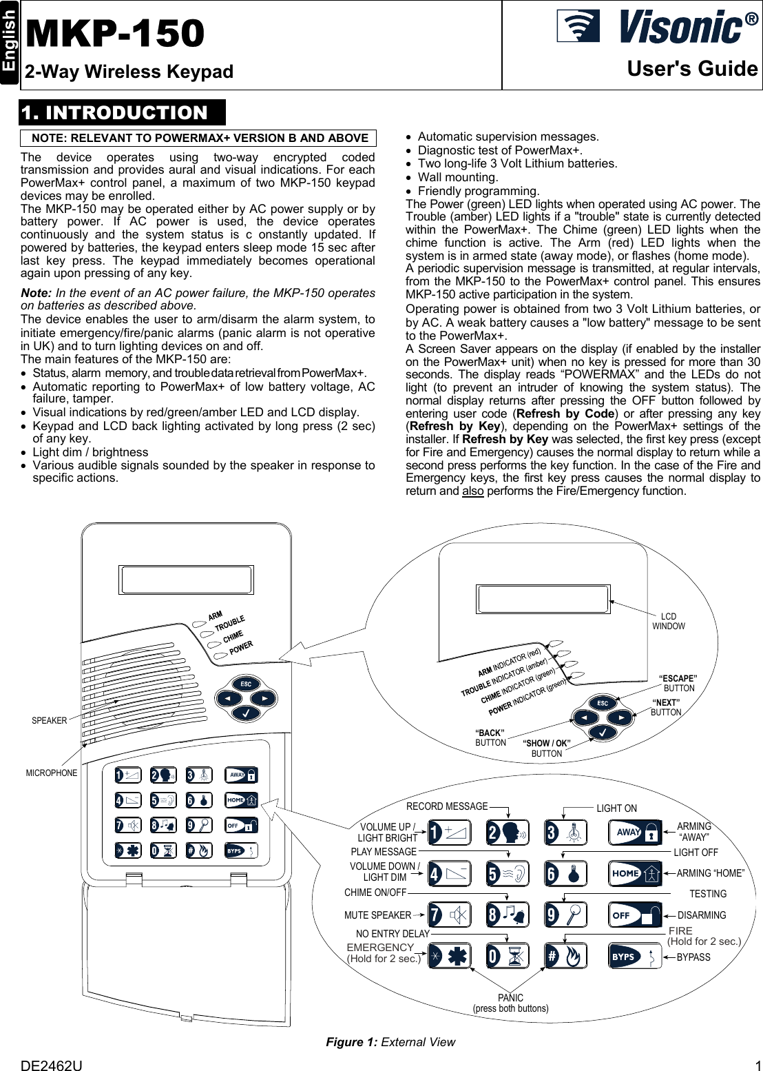
![4 DE2462U B. Press the Show / OK button (√). The display should read: ENTER CODE: ___ Note: For PowerMax+ that has two installer codes, the default INSTALLER code is 8888 and the default MASTER INSTALLER code is 9999. C. Enter the installer code. The display will change to: SUPERVISION D. Press <√>. E. Press <►> repeatedly to select one of the available options. F. Press <√> to set the selected option. 5.1.2 To Activate the Recording Mode A. Upon gaining access to the installer menu (see section 5.1.1 A to C), the display will read “SUPERVISION”. B. Press <►> repeatedly until RECORD SPEECH is displayed: C. Press <√>. The display will change to: USER TERM #1 Note: User Term refers to the name assigned to the recorded zone. Note: It is recommended to assign custom names that are identical to the custom names defined in the PowerMax+. D. Press the key until this is displayed briefly: RECORD A MESSAGE Immediately thereafter, the display will change to: TALK NOW E. Do not release the key and start talking immediately (for example, living room or library), while facing the front panel. The dark square boxes will slowly disappear one by one, from right to left. When the last one disappears (5 seconds later) the following message will be displayed: RECORDING ENDED F. Release the key. To check the message, press the key and listen to the playback. G. Press <►>. The display will change to: USER TERM #2 H. Repeat the procedure for User Terms #2 - 5 to record the names of zones 2 - 5. 5.1.3 To Enable/Disable Piezo Beeps A. Upon gaining access to the installer menu (see section 5.1.1, points A to C), the display will read “SUPERVISION”. B. Press <►>; PIEZO BEEP is displayed: C. Press <√>. D. Press <►> to select between enable beeps, off when home and disable beeps. E. Press <√> to set the selected option. 5.1.4 To Read the Device Serial Number A. Upon gaining access to the installer menu (see section 5.1.1, points A to C), the display will read “SUPERVISION”. B. Press <►> repeatedly until SERIAL NUMBER is displayed. C. Press <√> to read the serial number assigned to the unit. RECORD SPEECHuser term #1user term #2user term #3user term #4user term #5READY 00:00USER SETTINGNORMAL MODEENTER CODE[installer code]INSTALLER MODESUPERVISIONsuperv time 15msuperv time 1hdisablePIEZO BEEPSenable beepsdisable beepsSERIAL NUMBERj-2462-E vxxx.xoff when homeNote: The currently saved options are displayed with a dark box at the right side of the display.To review the options, repeatedly click or until the desired option is displayed, thenclick (a dark box will be displayed at the right side).(*)In Canada, “disable”must be selected.* Figure 8: Defining MKP-150 Functions 5.2 User Setting Functions The user settings on your MKP-150 keypad include the following functions (for instructions see PowerMax+ User Guide): • Set Bypass • Show Bypass • Recall Bypass • Set Phone Number • Set User Codes • Set Voice Option • Auto Arm Option • Auto Arm Time • Squawk Option • Light by Timer (for further details, see PowerMax+ User Guide, Para. 4.5 Automatic ON/OFF Control). • Light by Sensor (for further details, see PowerMax+ User Guide, Para. 4.5 Automatic ON/OFF Control). Make sure the system is not in Arm mode. The display should read: READY TO SET FUNCTIONS The user's menu is accessible only to those who know the master user code, which is 1Î1Î1Î1 by factory default. Use this code for initial access, and replace it with a new code known only to you, (see PowerMax+ User's Guide). A. Press the ► button twice. The display should read: USER SETTING B. Press the √. The display should read: ENTER CODE: ___ C. Enter your code. The display will change to: SET BYPASS Note: If the bypass function is disabled, the display will change to: SET PHONE NUMBER D. Having gained access to the user's menu, you may now select any other item on the User Settings menu as detailed in Figure 9.](https://usermanual.wiki/Visonic/MKP150/User-Guide-585821-Page-4.png)
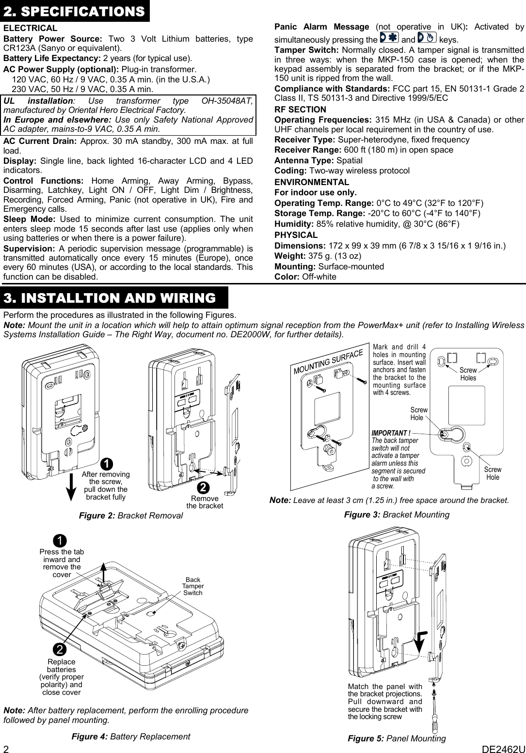
![DE2462U 5 NOTES(1) Function inside black rectangles are accessible only if master user code was entered.(2) Press OK to display the number, state and name of first bypassed zone. Press NEXT/BACK repeatedly to view all the bypassed zones.(3) To enter “A” (AM) press ( or one of the 3 keys above it), to enter “P” (PM) press (or one of the 3 keys above it). (Not functional if the time format has been set to the 24 hour clock via the PowerMax+.)(4) SET/SHOW/RECALL BYPASS menus are accessible only if “manual bypass” has been selected by the installer via the PowerMax+.(5) In the SET VOICE OPTION, if you select “enable prompts”, the PowerMax+ mute speaker button is active.SHOW BYPASSRECALL BYPASSBYPASS LIST<OK> TO RECALL(2)SET BYPASSNORMAL MODEREADY<OK> TO BYPASS Z01: BYPASSEDZ01: OPENKITCHENAlternatingKITCHENAlternating(for checking state of next zone)ENTER CODE _ _ _ _INSTALLER MODE(4)(4)(4) (example)SET PHONE NUMBER)SET USER CODES user code 1 0 0 0 0(for next user code 2, 3....8)[code]user code 1 user code1(example)(1)AUTO ARM OPTION disable autoarm enable autoarm(if it is the current option))[time]AUTO ARM TIME arm time _ _: _ _ASQUAWK OPTION(1)(1)(1)SET VOICE OPTION enable prompts(if it is the current option)(1)(5))[4-digit master/user code]if not satisfied)if not satisfied))disable prompts disable promptsenable autoarm(First display is READYor NOT READY)))))))))))))))))))))))))NEXTBACKMoving one levelup in the menuTo move within the menus, thefollowing keys can be used:SHOW / OKsquawk disablesqwk low volumesqwk mid volumesqwk hi volume(To review options, useNEXT or BACK button)Tel. N o .1st private tel#OKOKTel. No .2nd private tel#OKOKTel. No.3rd private tel#OKOKTel. No.4th private tel#OKOK)))OK OK OK OKLIGHT BY TIMERLIGHT BY SENSORenable disable disable)if not satisfied)enable disable disable)if not satisfiedUSER SETTINGS(1)(3)(1)ESC Figure 9: User Settings Flow Chart](https://usermanual.wiki/Visonic/MKP150/User-Guide-585821-Page-5.png)
![6 DE2462U 6. OPERATION Function Actions Arming HOME (1) (3) Arming HOME INSTANT (1) Arming AWAY AWAY (1) Arming AWAY INSTANT AWAY (1) Forced Arming HOME (1) Forced Arming AWAY AWAY (1) AWAYDisarming (1) X-10 device (1-15) ON unit # [1-15] X-10 device (1-15) OFF unit # [1-15] Light dim / brightness unit # [1-15]oror Emergency alarm (≈ 2 sec.) (5) Fire alarm (≈ 2 sec.) (5) Panic alarm (not operative in UK) Latchkey arming AWAY[user code](1)AWAY AWAY(2) Quick arm / HOME / AWAY AWAY (operates only if enabled in PowerMax+) Chime ON/OFF (press again to select option) Local Recording (press continuously while talking) Playback Local Voice On / Off Testing (1) (3) Bypass (1) Duress [duress code] (2580 by default) Notes 1. The factory default master user code is 1 1 1 1. The code is not required if quick arming has been permitted by the installer. 2. For LATCHKEY arming function, press the AWAY key, and then press the AWAY key again. 3. Pressing a non-valid code combination (not master / user code) causes a long failure beep. 4. If a keying sequence is not completed within a five second period, the desired function will not be executed. 5. Emergency, Fire or Panic buttons become active only if enabled in the PowerMax+. 7. COMPLIANCE WITH STANDARDSThis device complies with the essential requirements and provisions of Directive 1999/5/EC of the European Parliament and of the Council of 9 March 1999 on radio and telecommunications terminal equipment. Frequency Allocations for Wireless Devices in European Countries: • 315 MHz is not allowed in any EU member state. • 433.92 MHz has no restriction in any EU member state. • 868.95 MHz (wide band) is allowed in all EU member states. • 869.2625 MHz (narrow band) is not restricted in any EU member state. The user is cautioned that changes or modifications to the unit, not expressly approved by Visonic Ltd., could void the user's FCC or other authority to operate the equipment. The 315 MHz model of this device complies with Part 15 of the FCC Rules and RSS-210 of Industry and Science Canada. Operation is subject to these two conditions: (1) This device may not cause harmful interference, and (2) this device must accept any interference received, including interference that may cause undesirable operation. W.E.E.E. Product Recycling Declaration For information regarding the recycling of this product you must contact the company from which you orignially purchased it. If you are discarding this product and not returning it for repair then you must ensure that it is returned as identified by your supplier. This product is not to be thrown away with everyday waste. Directive 2002/96/EC Waste Electrical and Electronic Equipment. VISONIC LTD. (ISRAEL): P.O.B 22020 TEL-AVIV 61220 ISRAEL. PHONE: (972-3) 645-6789, FAX: (972-3) 645-6788 VISONIC INC. (U.S.A.): 65 WEST DUDLEY TOWN ROAD, BLOOMFIELD CT. 06002-1376. PHONE: (860) 243-0833, (800) 223-0020. FAX: (860) 242-8094 VISONIC LTD. (UK): FRASER ROAD, PRIORY BUSINESS PARK, BEDFORD MK44 3WH. PHONE: (0870) 7300800 FAX: (0870) 7300801 INTERNET: www.visonic.com VISONIC LTD. 2005 MKP-150 DE2462U (REV. 2, 8/05)](https://usermanual.wiki/Visonic/MKP150/User-Guide-585821-Page-6.png)