Visonic MKP150 2-Way Wireless Keypad User Manual MKP 150 for Arik
Visonic Inc. 2-Way Wireless Keypad MKP 150 for Arik
Visonic >
Users Manual
DE2462U 1
MKP-150
2-Way Wireless Keypad User's Guide
1. INTRODUCTION
NOTE: RELEVANT TO POWERMAX+ VERSION B AND ABOVE
The device operates using two-way encrypted coded
transmission and provides aural and visual indications. For each
PowerMax+ control panel, a maximum of two MKP-150 keypad
devices may be enrolled.
The MKP-150 may be operated either by AC power supply or by
battery power. If AC power is used, the device operates
continuously and the system status is c onstantly updated. If
powered by batteries, the keypad enters sleep mode 15 sec after
last key press. The keypad immediately becomes operational
again upon pressing of any key.
Note: In the event of an AC power failure, the MKP-150 operates
on batteries as described above.
The device enables the user to arm/disarm the alarm system, to
initiate emergency/fire/panic alarms (panic alarm is not operative
in UK) and to turn lighting devices on and off.
The main features of the MKP-150 are:
• Status, alarm memory, and trouble data retrieval from PowerMax+.
• Automatic reporting to PowerMax+ of low battery voltage, AC
failure, tamper.
• Visual indications by red/green/amber LED and LCD display.
• Keypad and LCD back lighting activated by long press (2 sec)
of any key.
• Light dim / brightness
• Various audible signals sounded by the speaker in response to
specific actions.
• Automatic supervision messages.
• Diagnostic test of PowerMax+.
• Two long-life 3 Volt Lithium batteries.
• Wall mounting.
• Friendly programming.
The Power (green) LED lights when operated using AC power. The
Trouble (amber) LED lights if a "trouble" state is currently detected
within the PowerMax+. The Chime (green) LED lights when the
chime function is active. The Arm (red) LED lights when the
system is in armed state (away mode), or flashes (home mode).
A periodic supervision message is transmitted, at regular intervals,
from the MKP-150 to the PowerMax+ control panel. This ensures
MKP-150 active participation in the system.
Operating power is obtained from two 3 Volt Lithium batteries, or
by AC. A weak battery causes a "low battery" message to be sent
to the PowerMax+.
A Screen Saver appears on the display (if enabled by the installer
on the PowerMax+ unit) when no key is pressed for more than 30
seconds. The display reads “POWERMAX” and the LEDs do not
light (to prevent an intruder of knowing the system status). The
normal display returns after pressing the OFF button followed by
entering user code (Refresh by Code) or after pressing any key
(Refresh by Key), depending on the PowerMax+ settings of the
installer. If Refresh by Key was selected, the first key press (except
for Fire and Emergency) causes the normal display to return while a
second press performs the key function. In the case of the Fire and
Emergency keys, the first key press causes the normal display to
return and also performs the Fire/Emergency function.
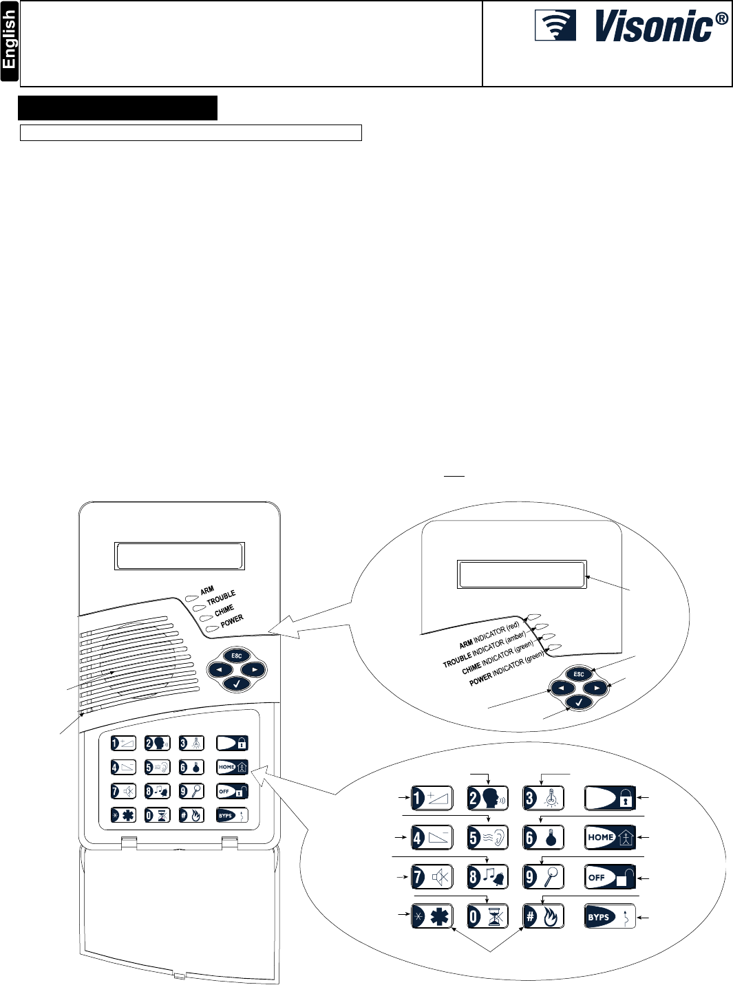
AWAY
MICROPHONE
PLAY MESSAGE
VOLUME UP /
LIGHT BRIGHT
VOLUME DOWN /
LIGHT DIM
CHIME ON/OFF
MUTE SPEAKER
NO ENTRY DELAY
RECORD MESSAGE
LIGHT OFF
TESTING
ARMING
“AWAY”
ARMING “HOME”
DISARMING
BYPASS
LIGHT ON
EMERGENCY
(Hold for 2 sec.)
(Hold for 2 sec.)
FIRE
PANIC
(press both buttons)
“SHOW / OK”
BUTTON
“ESCAPE”
BUTTON
“NEXT”
BUTTON
LCD
WINDOW
“BACK”
BUTTON
SPEAKER
AWAY
Figure 1: External View
2 DE2462U
2. SPECIFICATIONS
ELECTRICAL
Battery Power Source: Two 3 Volt Lithium batteries, type
CR123A (Sanyo or equivalent).
Battery Life Expectancy: 2 years (for typical use).
AC Power Supply (optional): Plug-in transformer.
120 VAC, 60 Hz / 9 VAC, 0.35 A min. (in the U.S.A.)
230 VAC, 50 Hz / 9 VAC, 0.35 A min.
UL installation: Use transformer type OH-35048AT,
manufactured by Oriental Hero Electrical Factory.
In Europe and elsewhere: Use only Safety National Approved
AC adapter, mains-to-9 VAC, 0.35 A min.
AC Current Drain: Approx. 30 mA standby, 300 mA max. at full
load.
Display: Single line, back lighted 16-character LCD and 4 LED
indicators.
Control Functions: Home Arming, Away Arming, Bypass,
Disarming, Latchkey, Light ON / OFF, Light Dim / Brightness,
Recording, Forced Arming, Panic (not operative in UK), Fire and
Emergency calls.
Sleep Mode: Used to minimize current consumption. The unit
enters sleep mode 15 seconds after last use (applies only when
using batteries or when there is a power failure).
Supervision: A periodic supervision message (programmable) is
transmitted automatically once every 15 minutes (Europe), once
every 60 minutes (USA), or according to the local standards. This
function can be disabled.
Panic Alarm Message (not operative in UK): Activated by
simultaneously pressing the and keys.
Tamper Switch: Normally closed. A tamper signal is transmitted
in three ways: when the MKP-150 case is opened; when the
keypad assembly is separated from the bracket; or if the MKP-
150 unit is ripped from the wall.
Compliance with Standards: FCC part 15, EN 50131-1 Grade 2
Class II, TS 50131-3 and Directive 1999/5/EC
RF SECTION
Operating Frequencies: 315 MHz (in USA & Canada) or other
UHF channels per local requirement in the country of use.
Receiver Type: Super-heterodyne, fixed frequency
Receiver Range: 600 ft (180 m) in open space
Antenna Type: Spatial
Coding: Two-way wireless protocol
ENVIRONMENTAL
For indoor use only.
Operating Temp. Range: 0°C to 49°C (32°F to 120°F)
Storage Temp. Range: -20°C to 60°C (-4°F to 140°F)
Humidity: 85% relative humidity, @ 30°C (86°F)
PHYSICAL
Dimensions: 172 x 99 x 39 mm (6 7/8 x 3 15/16 x 1 9/16 in.)
Weight: 375 g. (13 oz)
Mounting: Surface-mounted
Color: Off-white
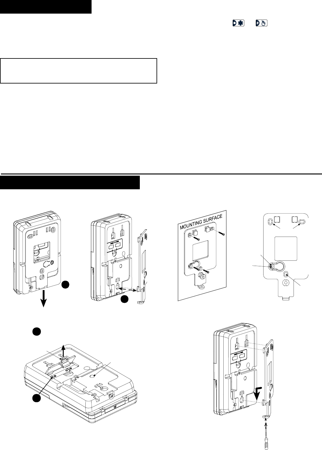
3. INSTALLTION AND WIRING
Perform the procedures as illustrated in the following Figures.
Note: Mount the unit in a location which will help to attain optimum signal reception from the PowerMax+ unit (refer to Installing Wireless
Systems Installation Guide – The Right Way, document no. DE2000W, for further details).
After removing
the screw,
pull down the
bracket fully
1
Remove
the bracket
2
Figure 2: Bracket Removal
Mark and drill 4
holes in mounting
surface. Insert wall
anchors and fasten
the bracket to the
mounting surface
with 4 screws.
Screw
Holes
Screw
Hole
IMPORTANT !
The back tamper
switch will not
activate a tamper
alarm unless this
segment is secured
to the wall with
a screw.
Screw
Hole
Note: Leave at least 3 cm (1.25 in.) free space around the bracket.
Figure 3: Bracket Mounting
2
1
Press the tab
inward and
remove the
cover
Replace
batteries
(verify proper
polarity) and
close cover
Back
Ta m p e r
Switch
Note: After battery replacement, perform the enrolling procedure
followed by panel mounting.
Figure 4: Battery Replacement
Match the panel with
the bracket projections.
Pull downward and
secure the bracket with
the locking screw
Figure 5: Panel Mounting
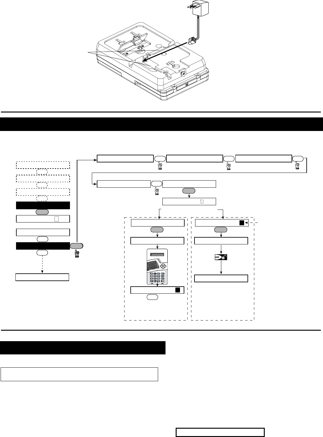
DE2462U 3
9
VAC
Wiring
Channels
Connect the 9 VAC
power supply to the
terminal block. Route
the wiring through the
wiring channels.
Note: The power
supply is optional
Figure 6: Wiring
4. ENROLLING/DELETING THE MKP-150 FROM THE POWERMAX+ MEMORY
To enroll all the MKP-150 functions (for complete list see PowerMax+ Installer Guide), enter the PowerMax+ Installer Mode from the
PowerMax+ keypad, and proceed as shown in the following illustration.
Note: Refer to PowerMax+
Installer Guide for details on
performing a diagnostic test
OK
(First display is READY
or NOT READY)
READY 00:00
USER SETTINGS
NORMAL MODE
ENTER CODE
1. NEW INSTL CODE
2. ENROLLING
[installer code]
INSTALLER MODE
ENROL WL 2WAY KP
ENROLL WL DEVICEENROLLING TYPE
[MKP-150 No. 1 to 2]
(e.g. 2)
2way kp No :
2way kp No : 2 2way kp No : 2
2way kp No: 2
Enrolling a wireless
Keypad MKP-150
for next
enrolling action
<OFF> TO DELETE
press back
tamper
switch
once
(see Fig. 4)
TRANSMIT NOW
Deleting a wireless
Keypad MKP-150
2way kp No: 2
ENROLL KEYFOB
Black rectangle means
that the MKP-150 No. 2
is already enrolled.
AWAY
OK
NEXT
NEXT
NEXT
NEXT
OK
OK
OK
NEXT
OK
NEXT NEXT NEXT
ENROL WL 1WAY KP NEXT
9. DIAGNOSTICS
NEXT
Figure 7: Enrolling / Deleting a MKP-150 Device from PowerMax+ Memory
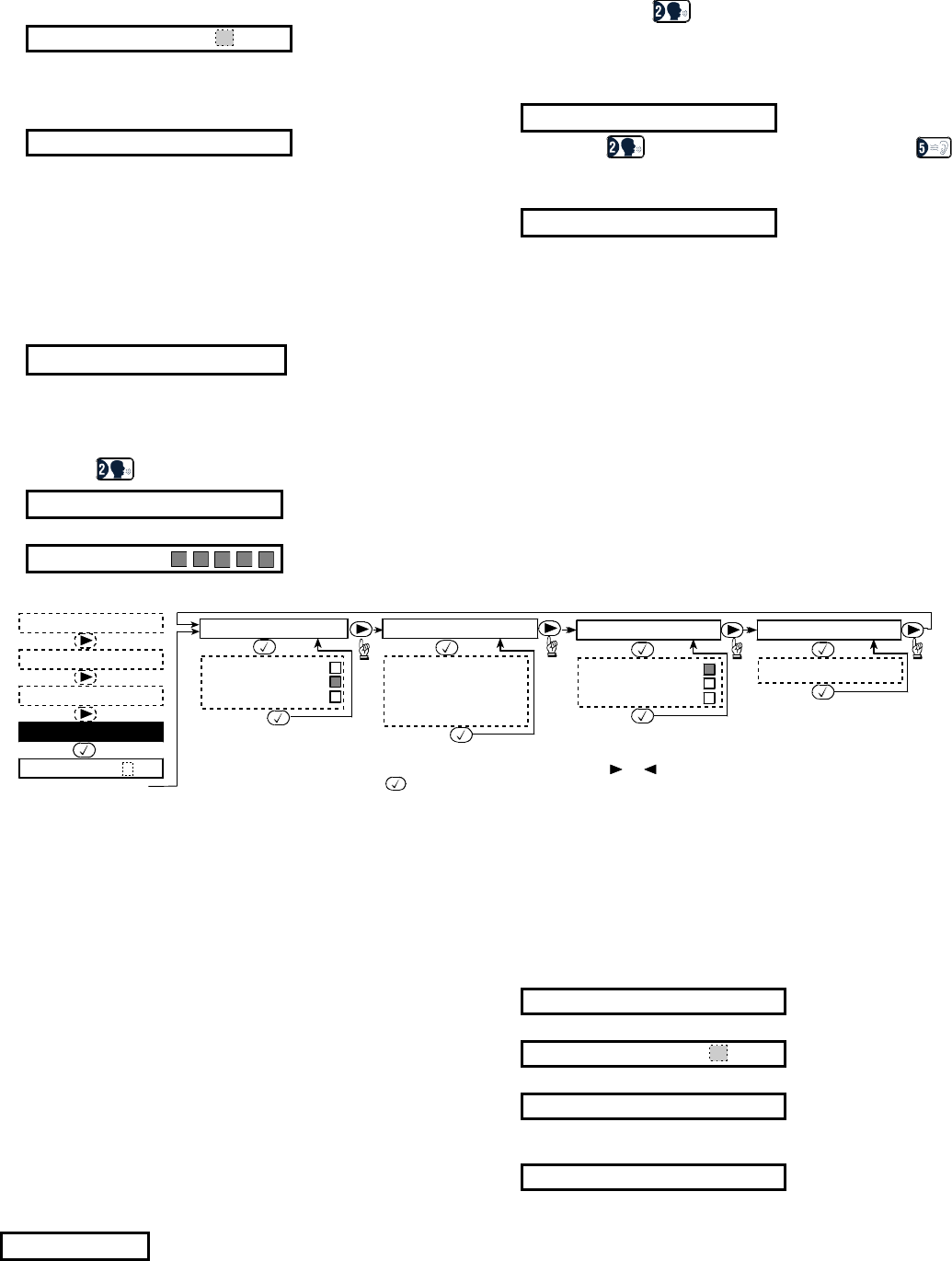
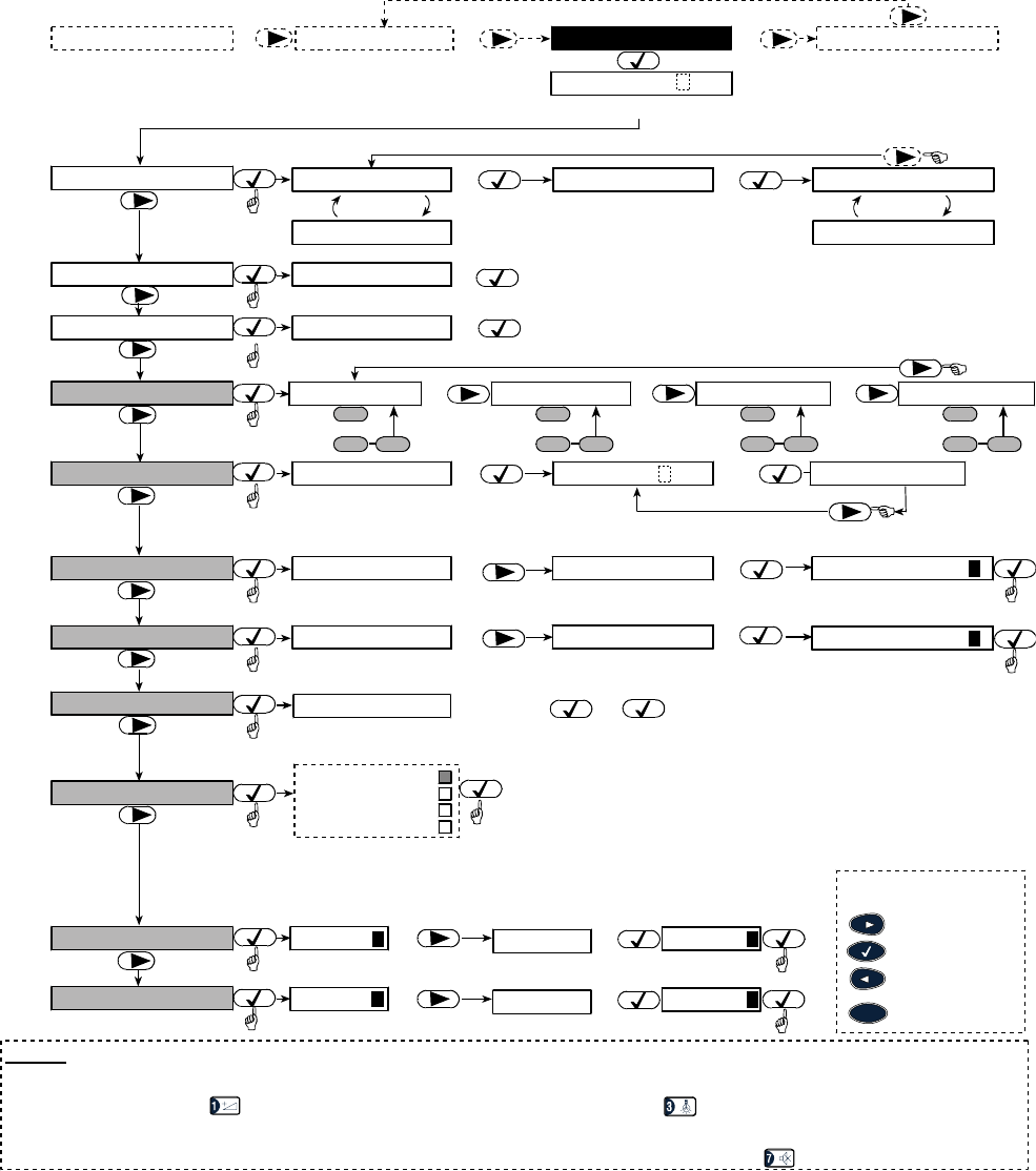
5. DEFINING MKP-150 PARAMETERS
5.1 Installer Menu Functions
Important: All installer settings affect only the specific keypad on
which the settings were performed.
The Installer menu enables you to perform three separate
functions, as follows:
SUPERVISION
The keypad transmits supervision reports periodically to the
PowerMax+.
The options are: 15 minutes, 1 hour and disable.
PIEZO BEEP
Here you determine whether warning beeps will sound or muted
during exit and entry delays.
Options: enable beeps, off when home and disable beeps.
RECORD SPEECH
This mode allows you to record up to 5 custom zone names.
SERIAL NUMBER
Enables reading the system serial number for support purposes
only.
5.1.1 To Set Supervision Time
Make sure the system is not in Arm mode.
The installer’s menu is accessible only to those who know the
installer’s code, which is 9Î9Î9Î9 by factory default.
A. Press the next button (►) repeatedly until the display reads:
INSTALLER MODE
4 DE2462U
B. Press the Show / OK button (√). The display should read:
ENTER CODE: ___
Note: For PowerMax+ that has two installer codes, the default
INSTALLER code is 8888 and the default MASTER
INSTALLER code is 9999.
C. Enter the installer code. The display will change to:
SUPERVISION
D. Press <√>.
E. Press <►> repeatedly to select one of the available options.
F. Press <√> to set the selected option.
5.1.2 To Activate the Recording Mode
A. Upon gaining access to the installer menu (see section 5.1.1
A to C), the display will read “SUPERVISION”.
B. Press <►> repeatedly until RECORD SPEECH is displayed:
C. Press <√>. The display will change to:
USER TERM #1
Note: User Term refers to the name assigned to the recorded
zone.
Note: It is recommended to assign custom names that are
identical to the custom names defined in the PowerMax+.
D. Press the key until this is displayed briefly:
RECORD A MESSAGE
Immediately thereafter, the display will change to:
TALK NOW
E. Do not release the key and start talking immediately (for
example, living room or library), while facing the front panel.
The dark square boxes will slowly disappear one by one, from
right to left. When the last one disappears (5 seconds later)
the following message will be displayed:
RECORDING ENDED
F. Release the key. To check the message, press the
key and listen to the playback.
G. Press <►>. The display will change to:
USER TERM #2
H. Repeat the procedure for User Terms #2 - 5 to record the
names of zones 2 - 5.
5.1.3 To Enable/Disable Piezo Beeps
A. Upon gaining access to the installer menu (see section 5.1.1,
points A to C), the display will read “SUPERVISION”.
B. Press <►>; PIEZO BEEP is displayed:
C. Press <√>.
D. Press <►> to select between enable beeps, off when home
and disable beeps.
E. Press <√> to set the selected option.
5.1.4 To Read the Device Serial Number
A. Upon gaining access to the installer menu (see section 5.1.1,
points A to C), the display will read “SUPERVISION”.
B. Press <►> repeatedly until SERIAL NUMBER is displayed.
C. Press <√> to read the serial number assigned to the unit.
RECORD SPEECH
user term #1
user term #2
user term #3
user term #4
user term #5
READY 00:00
USER SETTING
NORMAL MODE
ENTER CODE
[installer code]
INSTALLER MODE
SUPERVISION
superv time 15m
superv time 1h
disable
PIEZO BEEPS
enable beeps
disable beeps
SERIAL NUMBER
j-2462-E vxxx.x
off when home
Note: The currently saved options are displayed with a dark box at the right side of the display.
To review the options, repeatedly click or until the desired option is displayed, then
click (a dark box will be displayed at the right side).
(*)
In Canada, “disable”
must be selected.
*
Figure 8: Defining MKP-150 Functions
5.2 User Setting Functions
The user settings on your MKP-150 keypad include the following
functions (for instructions see PowerMax+ User Guide):
• Set Bypass
• Show Bypass
• Recall Bypass
• Set Phone Number
• Set User Codes
• Set Voice Option
• Auto Arm Option
• Auto Arm Time
• Squawk Option
• Light by Timer (for further details, see PowerMax+ User Guide,
Para. 4.5 Automatic ON/OFF Control).
• Light by Sensor (for further details, see PowerMax+ User
Guide, Para. 4.5 Automatic ON/OFF Control).
Make sure the system is not in Arm mode. The display should read:
READY
TO SET FUNCTIONS
The user's menu is accessible only to those who know the master
user code, which is 1Î1Î1Î1 by factory default.
Use this code for initial access, and replace it with a new code
known only to you, (see PowerMax+ User's Guide).
A. Press the ► button twice.
The display should read:
USER SETTING
B. Press the √. The display should read:
ENTER CODE: ___
C. Enter your code. The display will change to:
SET BYPASS
Note: If the bypass function is disabled, the display will
change to:
SET PHONE NUMBER
D. Having gained access to the user's menu, you may now select
any other item on the User Settings menu as detailed in Figure 9.
DE2462U 5
NOTES
(1) Function inside black rectangles are accessible only if master user code was entered.
(2) Press OK to display the number, state and name of first bypassed zone. Press NEXT/BACK repeatedly to view all the bypassed zones.
(3) To enter “A” (AM) press ( or one of the 3 keys above it), to enter “P” (PM) press (or one of the 3 keys above it). (Not
functional if the time format has been set to the 24 hour clock via the PowerMax+.)
(4) SET/SHOW/RECALL BYPASS menus are accessible only if “manual bypass” has been selected by the installer via the PowerMax+.
(5) In the SET VOICE OPTION, if you select “enable prompts”, the PowerMax+ mute speaker button is active.
SHOW BYPASS
RECALL BYPASS
BYPASS LIST
<OK> TO RECALL
(2)
SET BYPASS
NORMAL MODEREADY
<OK> TO BYPASS Z01: BYPASSED
Z01: OPEN
KITCHEN
Alternating
KITCHEN
Alternating
(for checking state of next zone)
ENTER CODE _ _ _ _
INSTALLER MODE
(4)
(4)
(4) (example)
SET PHONE NUMBER
)
SET USER CODES user code 1 0 0 0 0
(for next user code 2, 3....8)
[code]
user code 1 user code1
(example)
(1)
AUTO ARM OPTION disable autoarm enable autoarm
(if it is the current option)
)[time]
AUTO ARM TIME arm time _ _: _ _A
SQUAWK OPTION
(1)
(1)
(1)
SET VOICE OPTION enable prompts
(if it is the current option)
(1)(5)
)[4-digit master/user code]
if not satisfied
)
if not satisfied
)
)
disable prompts disable prompts
enable autoarm
(First display is READY
or NOT READY)
)
)
)
)
)
)
)
)
)
)
)
)
)
)
)
)
)
)))
)
))
)
NEXT
BACK
Moving one level
up in the menu
To move within the menus, the
following keys can be used:
SHOW / OK
squawk disable
sqwk low volume
sqwk mid volume
sqwk hi volume
(To review options, use
NEXT or BACK button)
Tel. N o .
1st private tel#
OK
OK
Tel. No .
2nd private tel#
OK
OK
Tel. No.
3rd private tel#
OK
OK
Tel. No.
4th private tel#
OK
OK
)))
OK OK OK OK
LIGHT BY TIMER
LIGHT BY SENSOR
enable disable disable
)
if not satisfied
)
enable disable disable
)
if not satisfied
USER SETTINGS
(1)
(3)
(1)
ESC
Figure 9: User Settings Flow Chart
6 DE2462U
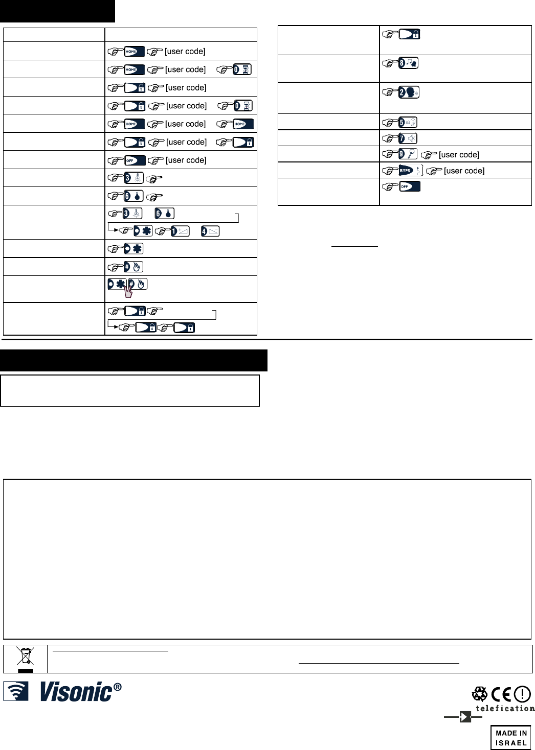
6. OPERATION
Function Actions
Arming HOME (1) (3)
Arming HOME INSTANT (1)
Arming AWAY
AWAY
(1)
Arming AWAY INSTANT
AWAY
(1)
Forced Arming HOME (1)
Forced Arming AWAY
AWAY
(1)
AWAY
Disarming (1)
X-10 device (1-15) ON unit # [1-15]
X-10 device (1-15) OFF unit # [1-15]
Light dim / brightness unit # [1-15]
or
or
Emergency alarm (≈ 2 sec.) (5)
Fire alarm (≈ 2 sec.) (5)
Panic alarm (not
operative in UK)
Latchkey arming
AWAY
[user code](1)
AWAY AWAY
(2)
Quick arm / HOME /
AWAY
AWAY
(operates only if enabled in
PowerMax+)
Chime ON/OFF (press again to select
option)
Local Recording (press continuously while
talking)
Playback
Local Voice On / Off
Testing (1) (3)
Bypass (1)
Duress [duress code] (2580 by
default)
Notes
1. The factory default master user code is 1 1 1 1. The code is not
required if quick arming has been permitted by the installer.
2. For LATCHKEY arming function, press the AWAY key, and
then press the AWAY key again.
3. Pressing a non-valid code combination (not master / user
code) causes a long failure beep.
4. If a keying sequence is not completed within a five second
period, the desired function will not be executed.
5. Emergency, Fire or Panic buttons become active only if
enabled in the PowerMax+.
7. COMPLIANCE WITH STANDARDS
This device complies with the essential requirements and provisions of
Directive 1999/5/EC of the European Parliament and of the Council of 9
March 1999 on radio and telecommunications terminal equipment.
Frequency Allocations for Wireless Devices in European
Countries:
• 315 MHz is not allowed in any EU member state.
• 433.92 MHz has no restriction in any EU member state.
• 868.95 MHz (wide band) is allowed in all EU member states.
• 869.2625 MHz (narrow band) is not restricted in any EU
member state.
The user is cautioned that changes or modifications to the unit,
not expressly approved by Visonic Ltd., could void the user's FCC
or other authority to operate the equipment.
The 315 MHz model of this device complies with Part 15 of the
FCC Rules and RSS-210 of Industry and Science Canada.
Operation is subject to these two conditions: (1) This device may
not cause harmful interference, and (2) this device must accept
any interference received, including interference that may cause
undesirable operation.
W.E.E.E. Product Recycling Declaration
For information regarding the recycling of this product you must contact the company from which you orignially purchased it. If you are discarding this product and not
returning it for repair then you must ensure that it is returned as identified by your supplier. This product is not to be thrown away with everyday waste.
Directive 2002/96/EC Waste Electrical and Electronic Equipment.
VISONIC LTD. (ISRAEL): P.O.B 22020 TEL-AVIV 61220 ISRAEL. PHONE: (972-3) 645-6789, FAX: (972-3) 645-6788
VISONIC INC. (U.S.A.): 65 WEST DUDLEY TOWN ROAD, BLOOMFIELD CT. 06002-1376. PHONE: (860) 243-0833, (800) 223-0020. FAX: (860) 242-8094
VISONIC LTD. (UK): FRASER ROAD, PRIORY BUSINESS PARK, BEDFORD MK44 3WH. PHONE: (0870) 7300800 FAX: (0870) 7300801
INTERNET: www.visonic.com
VISONIC LTD. 2005 MKP-150 DE2462U (REV. 2, 8/05)

2 DE2380
WARRANTY
WARRANTYWARRANTY
WARRANTY
Visonic Ltd. and/or its subsidiaries and its affiliates ("the Manufacturer") warrants its
products hereinafter referred to as "the Product" or "Products" to be in conformance with
its own plans and specifications and to be free of defects in materials and workmanship
under normal use and service for a period of twelve months from the date of shipment by
the Manufacturer. The Manufacturer's obligations shall be limited within the warranty
period, at its option, to repair or replace the product or any part thereof. The Manufacturer
shall not be responsible for dismantling and/or reinstallation charges. To exercise the
warranty the product must be returned to the Manufacturer freight prepaid and insured.
This warranty does not apply in the following cases: improper installation, misuse,
failure to follow installation and operating instructions, alteration, abuse, accident or
tampering, and repair by anyone other than the Manufacturer.
This warranty is exclusive and expressly in lieu of all other warranties, obligations or
liabilities, whether written, oral, express or implied, including any warranty of
merchantability or fitness for a particular purpose, or otherwise. In no case shall the
Manufacturer be liable to anyone for any consequential or incidental damages for breach
of this warranty or any other warranties whatsoever, as aforesaid.
This warranty shall not be modified, varied or extended, and the Manufacturer does not
authorize any person to act on its behalf in the modification, variation or extension of this
warranty. This warranty shall apply to the Product only. All products, accessories or
attachments of others used in conjunction with the Product, including batteries, shall be
covered solely by their own warranty, if any. The Manufacturer shall not be liable for any
damage or loss whatsoever, whether directly, indirectly, incidentally, consequentially or
otherwise, caused by the malfunction of the Product due to products, accessories, or
attachments of others, including batteries, used in conjunction with the Products.
The Manufacturer does not represent that its Product may not be compromised and/or
circumvented, or that the Product will prevent any death, personal and/or bodily injury
and/or damage to property resulting from burglary, robbery, fire or otherwise, or that the
Product will in all cases provide adequate warning or protection. User understands that a
properly installed and maintained alarm may only reduce the risk of events such as
burglary, robbery, and fire without warning, but it is not insurance or a guarantee that such
will not occur or that there will be no death, personal damage and/or damage to property
as a result.
The Manufacturer shall have no liability for any death, personal and/or bodily injury
and/or damage to property or other loss whether direct, indirect, incidental,
consequential or otherwise, based on a claim that the Product failed to function.
However, if the Manufacturer is held liable, whether directly or indirectly, for any loss or
damage arising under this limited warranty or otherwise, regardless of cause or origin, the
Manufacturer's maximum liability shall not in any case exceed the purchase price of the
Product, which shall be fixed as liquidated damages and not as a penalty, and shall be the
complete and exclusive remedy against the Manufacturer.
Warning: The user should follow the installation and operation instructions and among
other things test the Product and the whole system at least once a week. For various
reasons, including, but not limited to, changes in environmental conditions, electric or
electronic disruptions and tampering, the Product may not perform as expected. The user
is advised to take all necessary precautions for his /her safety and the protection of
his/her property.
6/91
The digital circuit of this device has been tested and found to comply with the limits for a Class B digital device, pursuant to
Part15 of the FCC Rules. These limits are designed to provide reasonable protection against harmful interference in residential
installations. This equipment generates, uses and can radiate radio frequency energy and, if not installed and used in
accordance with the instructions, may cause harmful interference to radio and television reception. However, there is no
guarantee that interference will not occur in a particular installation. If this device does cause such interference, which can be
verified by turning the device off and on, the user is encouraged to eliminate the interference by one or more of the following
measures:
– Re-orient or re-locate the receiving antenna.
– Increase the distance between the device and the receiver.
– Connect the device to an outlet on a circuit different from the
one which supplies power to the receiver.
– Consult the dealer or an experienced radio/TV technician.
VISONIC LTD (ISRAEL): P.O.B 22020 TEL-AVIV 61220 ISRAEL. PHONE: (972-3) 645-6789, FAX: (972-3) 645-6788
VISONIC INC. (U.S.A.): 10 NORTHWOOD DRIVE, BLOOMFIELD CT. 06002-1911. PHONE: (860) 243-0833, (800) 223-0020 FAX: (860) 242-8094
VISONIC LTD. (UK): FRASER ROAD, PRIORY BUSINESS PARK, BEDFORD MK44 3WH. PHONE: (0870) 7300800 FAX: (0870) 7300801
INTERNET: WWW.VISONIC.COM