Visonic MP802PG2 Wireless Digital Pet Immune PIR Detector User Manual MP 802 K9 85 PG2 Installation Instructions
Visonic Ltd. Wireless Digital Pet Immune PIR Detector MP 802 K9 85 PG2 Installation Instructions
Visonic >
Contents
- 1. Users Manual
- 2. Users Manual_1
- 3. Users Manual_2
Users Manual
D-306133 MP-802 K9-85 PG2 Installation Instructions 1
1. INTRODUCTION
The MP-802 K9-85 PG2 (pet immune) is a microprocessor-controlled wireless digital PIR detector
supported by the PowerMaster alarm system using PowerG two-way communication protocol.
The detector's features are as follows:
lFresnel and cylindrical lenses with uniform detection sensitivity throughout its operating range, up to 12
meters (39 ft).
lTarget Specific Imaging™ (TSI) technology is used for distinction between humans and pets weighing
up to 38 kg (85lb).
lThe advanced True Motion Recognition™ algorithm (patented) allows distinguishing between the true
motion of an intruder and any other disturbances which may cause false alarms.
lNo vertical adjustment is needed.
lMotion event counter determines whether 1 or 2 consecutive motion events trigger an alarm.
lVery low current consumption.
lMicroprocessor-controlled temperature compensation. Sealed black chamber provides white light
protection.
lFront and back tamper protection.
lThe device supports temperature and light level reports according to the PowerG panel.
For UL installations: The detector is for use with UL listed control unit only. Pet immunity has not been
evaluated by UL.
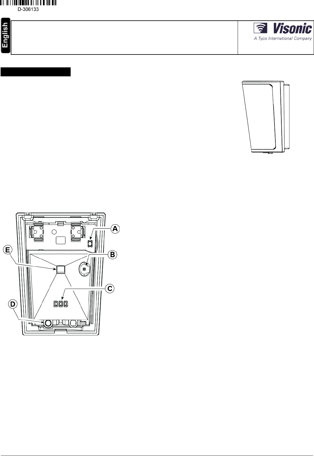
............. ........Figure 2 - Internal View
Figure 1: MP-802 K9-85 PG2
A. Enroll button
B. Light sensor
C. LEDs
D. Tamper switch
E. PIR sensor
MP-802 K9-85 PG2
Wireless Digital Pet Immune PIR Detector
Installation Instructions
2. INSTALLATION
2.1. General Guidance
1. Keep away from heat sources.
2. Do not expose to air drafts.
3. Do not install outdoors.
4. Avoid direct sunshine.
5. Do not install near high-voltage electrical line.
6. Do not install behind partitions.
7. Mount on solid stable surface.
Warning! Do not obscure partially or completely the detector's field of
view.
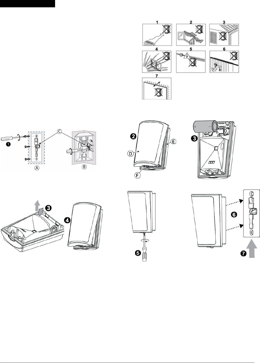
Figure 3 - General Guidelines
2.2. Installation Procedure
Figure 4 - Bracket Mounting
Figure 5 - Opening the Unit Figure 6a - Battery Insertion
Figure 6b - Battery Activation Figure 7 - Closing the Cover
Figure 8 - Securing with Screw Figure 9 - Mounting Detector on
Bracket
1. Mount the bracket on the wall.
2. Press in the point marked "F" in the drawing and separate the cover from the base.
3. Insert the battery while observing polarity-OR- If battery is already installed, pull the activation strip that
protrudes from the front of the detector.
4. Return the cover to the base until a click is heard (the snap is closed).
5. Secure detector with screw.
6. Align the detector with the bracket.
7. Slide the detector upward until a click is heard.
A. Surface mounting
B. Corner mounting
C. For back tamper
..................... .D. Cover
........ ............E. Base
F. Press in this point
Note: The detector transmits a low battery signal upon detection of low voltage. It is recommended to wait about 1 minute after battery removal, before
inserting the new battery.
MP-802 K9-85 shall be installed in accordance with the Standard for Installation and Classification of Burglar and Holdup Alarm Systems, UL 681.
Caution! Risk of explosion if battery is replaced by an incorrect type. Dispose of used battery according to the manufacturer's instructions.
D-306133 MP-802 K9-85 PG2 Installation Instructions 2
2.3. Removing the Pet Mask
Remove the plastic (pet mask) if you do not require pet immunity.
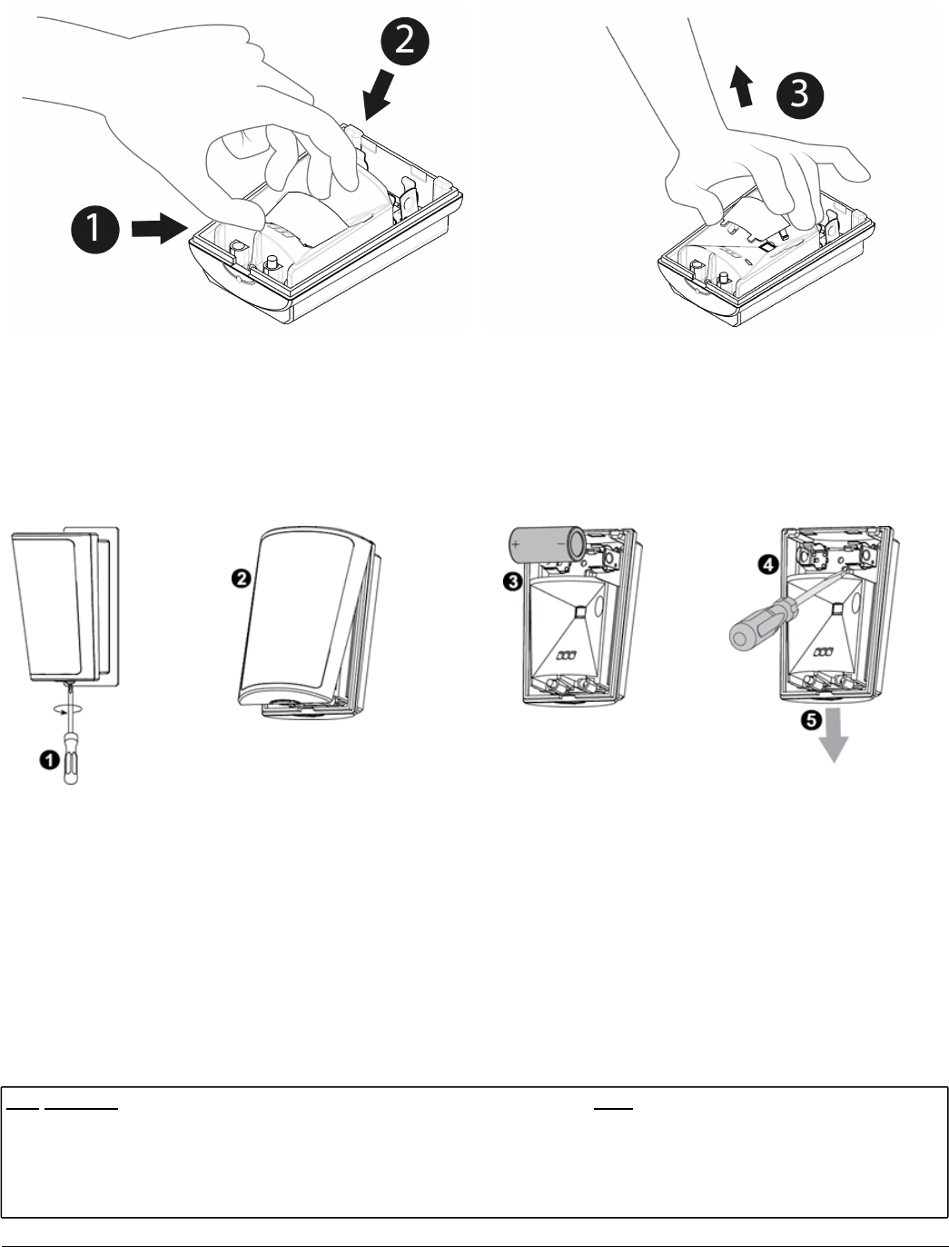
Figure 10 - Removing the Pet Mask
1. Place your thumb at the base of the Pet Mask.
2. Place your fingers at the top of the Pet Mask.
3. Lift the Pet Mask to remove.
2.4. Disassembly from Bracket
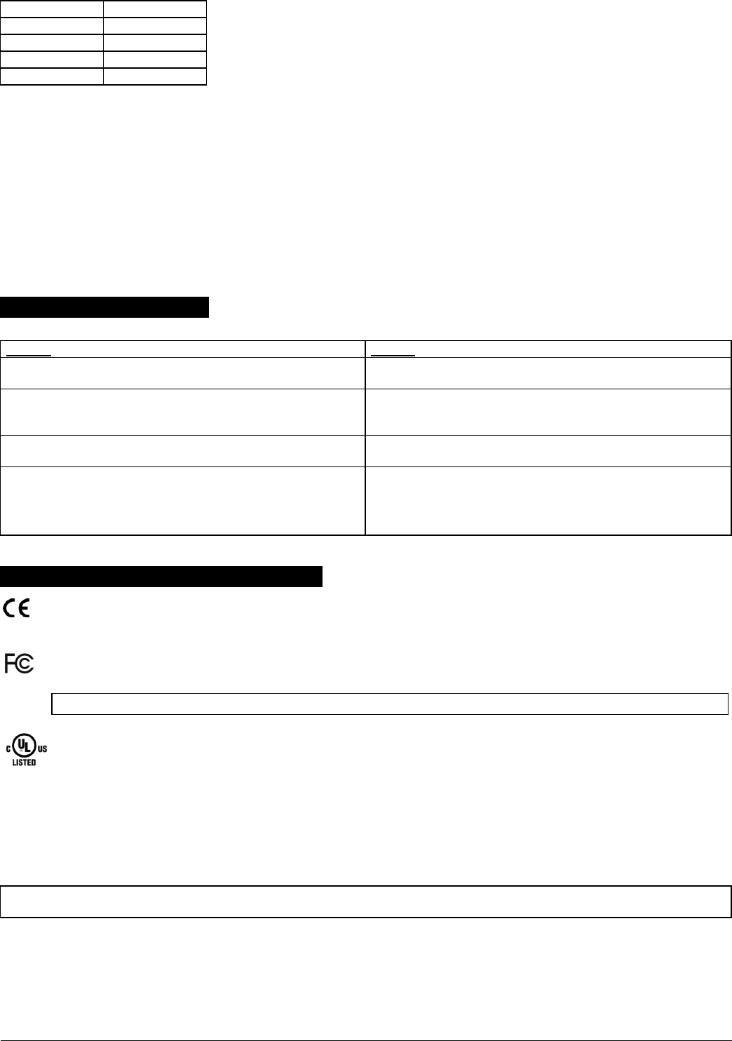
Figure 11 - Disassembly from Bracket
1. Release screw.
2. Separate the cover from the base.
3. Remove battery.
4. Press on the stopper snap to release the base from the bracket.
5. Slide the base downward to remove.
2.5. Enrollment
Refer to the PowerMaster panel's Installer Guide and follow the procedure under the "02:ZONES/DEVICES" option of the Installer Menu. A general
description of the procedure is provided in the following flow chart.
Step Procedure Menu
1 Enter the installer menu and select “02:ZONES/DEVICES” 02:ZONES/DEVICES
2 Select “ADD NEW DEVICES” Option – See Note [1]
ADD NEW DEVICES
↓
MODIFY DEVICES
D-306133 MP-802 K9-85 PG2 Installation Instructions 3

3Select “ADD NEW DEVICES” Option – See Note [1] Enroll the device or enter the
device ID ENROLL NOW or ENTR ID:XXX-XXXX
4 Select the desired Zone Number
Z14:Motion Sens (with panels PowerG V19.2 and
lower)
ID No. 120-XXXX (with panels PowerG V19.2 and
lower)
Z14:S.Motion (with panels PowerG V19.3 and higher)
ID No. 126-XXXX (with panels PowerG V19.3 and
higher)
5 Configure Location, Zone Type & Chime Parameters
Z14:LOCATION
Z14:ZONE TYPE
Z14:SET CHIME
Z14 :DEV SETTINGS
6 Configure the detector See Note 2
Notes:
[1] If the detector is already enrolled, you can configure the detector parameters via the modify devices option – see step 2.
[2] Select the “Device Settings” option and refer to section 3 to configure the detector parameters.
3. Temperature Display
For instructions on displaying the temperature of zones on the control panel as measured by MP-802 PG2 detectors, refer to the PowerMaster Installer
Guide, section 4.2 “Conducting a Periodic Test”.
4. Configuring the Detector Parameters
Enter the DEVICE SETTINGS menu and follow the configuration instructions for the MCP-802 K9-85 PG2 detector as described in the following table.
Option Configuring Instructions
Alarm LED Define whether or not the alarm LED indication will be activated. Optional settings: LED ON (default) and LED OFF.
Event
Counter
Define whether an alarm will be activated upon continued motion (low sensitivity) or upon a single alarm event (high sensitivity).
Optional settings: LOW sensitive (default) and HIGH sensitive.
DISARM
Activity
Define whether or not to set the activity time during disarm. Optional settings: NOT Active (default), YES – no delay, YES + 5s delay,
YES + 15s delay, YES + 30s delay, YES + 1m delay, YES + 2m delay, YES + 5m delay, YES + 10m delay, YES + 20m delay and YES +
60m delay.
VERY HOT
> 35°C [
>95°F]
Define whether or not the control panel will report a "very hot" alert when the temperature rises above 35°C (95°F) for at least 10
minutes. Alert restore will occur when the temperature drops below 34°C (93°F) for the duration of 10 minutes. Optional settings:
Disable (default) or Enable
COLD <
19°C [
<66°F]*
Define whether or not the control panel will report a "cold" alert when the temperature drops below 19°C (66°F) for at least 10
minutes. Alert restore will occur when the temperature rises above 20°C (68°F) for the duration of 10 minutes. Optional settings:
Disable (default) or Enable
FREEZING
< 7°C [
<45°F]*
Define whether or not the control panel will report a "freezing" alert when the temperature drops below 7°C (45°F) for at least 10
minutes. Alert restore will occur when the temperature rises above 8°C (48°F) for the duration of 10 minutes. Optional settings:
Disable (default) or Enable
FREEZER
> -10°C [
<14°F]*
Define whether or not the control panel will report a "freezer" alert when the temperature rises above -10°C (14°F) for at least 30
minutes. Alert restore will occur when the temperature drops below -11°C (12°F) for the duration of 10 minutes. Optional settings:
Disable (default) or Enable
Note: The temperature must pass beyond the threshold for the required duration in order to generate an alarm or restore transmission.
5. LOCAL DIAGNOSTICS TEST
Note: Run a diagnostic test at least once a year to ensure that the detector is working correctly.
1. Separate the base from the cover (see Figure 5).
2. Replace the cover to return the tamper switch to its normal (undisturbed) position, and then secure the front cover to the base with the case closure
screw.
3. The MP-802 K9-85 PG2 detector will enter a 2 min. stability period. During this time the red LED blinks.
4. Walk-test the coverage area – see Figure 12. Walk across the far end of the coverage pattern in both directions. The red LED lights each time your
motion is detected followed by 3 LED blinks.
The following table outlines received signal strength indication:
D-306133 MP-802 K9-85 PG2 Installation Instructions 4
LED response Reception
Green LED blinks Strong
Orange LED blinks Good
Red LED blinks Poor
No blinks No communication
Important! Instruct the user to walk test at least once a week to verify proper function of the detector.
Important! Reliable reception must be assured. Therefore, poor signal strength is not acceptable. If you receive a poor signal from the device, re-
locate it and re-test until a good or strong signal strength is received (in regions requiring UL-compliant installation, only strong signal strength is
permitted).
Notes:
[1] For detailed diagnostics test instructions, refer to the control panel Installer Guide.
**This menu appears in PowerMaster V19.3 or above only. In earlier versions, this menu will appear only after completing the following procedure:
a. Upgrade the PowerMaster control panel to V19.3 or above.
b. Delete the MP-802 K9-85 PG2 detector from the PowerMaster control panel.
c. Enroll the detector to the PowerMaster control panel again.
6. TROUBLESHOOTING
If you encounter one of the following problemswith the MP-802 K9-85 PG2, perform the suggested remedy from the following table:
Problem Remedy
Attempt to enroll the sensor is unsuccessful. Ensure that the sensor has been defaulted and is set to enroll mode (see
section 2.5)
The sensor and the panel do not communicate. Perform the signal strength testing procedure described in the control
panel installation manual. Make sure that the signal is sufficient. If
necessary, replace the sensor's battery.
The sensor sends a low battery indication. To ensure continuous proper operation, replace the battery within two
weeks of the first low battery indication.
Panel does not arm because of an unrecognized sensor malfunction. Consult with your installer or system provider before you
disable a zone.
Disable the sensor zone (see the control panel user manual). Note that
disabling a sensor zone lowers the overall security level of your system.
7. COMPLIANCE WITH STANDARDS
The MP-802 K9-85 PG2 complies with the following standards:
Europe:EN 300220, EN 301489, EN 60950-1, EN 50130-4, EN 50131-1, EN 50131-2-2 Grade 2 Class II, EN 50130-5, EN 50131-6 Type C
UK: The MP-802 K9-85 PG2 is suitable for use in systems installed to conform to PD6662:2010 at Grade 2 and environmental CLASS II. DD243 and BS8243
Certified by Applica Test & Certification AS in accordance with EN 50131-2-2, EN 50131-5-3, EN 50131-6, EN 50130-4, EN 50130-5 Applica T&C has certified
only the 868 MHz variant of this product.
The MP-802 K9-85 PG2 is compatible with the RED Directive 2014/53/EU of the European Parliament and of the Council of 16 April 2014
USA: FCC-CFR 47 Part 15, UL- UL 639
Canada:IC-RSS 247, ULC – S306
This device complies with Part 15 of the FCC Rules and RSS-247 of Industry and Science Canada. Operation is subject to the following two conditions:
(1) This device may not cause harmful interference, and (2) this device must accept any interference received, including interference that may cause
undesired operation.
Le présent appareil est conforme aux CNR d'Industrie Canada applicables aux appareils radio exempts de licence. L'exploitation est autorisée aux deux
conditions suivantes : (1) l'appareil ne doit pas produire de brouillage, et (2) l'utilisateur de l'appareil doit accepter tout brouillage radioélectrique subi,
même si le brouillage est susceptible d'en compromettre le fonctionnement.
WARNING! Changes or modifications to this unit not expressly approved by the party responsible for compliance could void the user’s authority to
operate the equipment.
To comply with FCC and IC RF exposure compliance requirements, the device should be located at a distance of at least 20 cm from all persons during
normal operation. The antennas used for this product must not be co-located or operated in conjunction with any other antenna or transmitter.
Le dispositif doit être placé à une distance d'au moins 20 cm à partir de toutes les personnes au cours de son fonctionnement normal. Les antennes
utilisées pour ce produit ne doivent pas être situés ou exploités conjointement avec une autre antenne ou transmetteur.
D-306133 MP-802 K9-85 PG2 Installation Instructions 5
NOTE: This equipment has been tested and found to comply with the limits for a Class B digital device, pursuant to part 15 of the FCC Rules. These
limits are designed to provide reasonable protection against harmful interference in a residential installation. This equipment generates, uses and can
radiate radio frequency energy and, if not installed and used in accordance with the instructions, may cause harmful interference to radio
communications. However, there is no guarantee that interference will not occur in a particular installation. If this equipment does cause harmful
interference to radio or television reception, which can be determined by turning the equipment off and on, the user is encouraged to try to correct the
interference by one or more of the following measures:
-Reorient or relocate the receiving antenna.
-Increase the separation between the equipment and receiver.
-Connect the equipment into an outlet on a circuit different from that to which the receiver is connected.
-Consult the dealer or an experienced radio/TV technician for help.
Cet équipement a été testé et jugé conforme aux limites s’appliquant à un appareil numérique de classe B, conformément à la Partie 15 des
réglementations de la FCC. Ces limites ont été élaborées pour offrir une protection raisonnable contre les interferences nuisibles dans une installation
résidentille.
Cet équipement génère, utilize et peut émettre de l’énergie de fréquence radio et, s’il n’est pas installé et utilize conformément aux instructions du
fabricant, peut provoquer des interférences dangereuses pour les communications radio. Toutefois, rien ne garantit l’absence d’interférences dans une
installation particuliére. Si cet équipement provoque des interférences nuisibles au niveau de la réception radio ou television, ce qui peut étre determine
par la mise hors, puis sous tension de l’équipment, vous étes invite à essayer de corriger les interferences en pregnant les mesures suivantes:
• Réorientez ou déplaces l’antenne réceptrice.
• Augmentez la distance qui sépare l’équipement et le récepteur.
• Branchez l’équipement à une prise d’un circuit different de celui auquel est branché le récepteur.
• Consultez le revendeur ou un technician radio/television expérimenté pour obtenir de l’aide
8. Special Comments
Even the most sophisticated detectors can sometimes be defeated or may fail to warn due to: DC power failure / improper connection, malicious
masking of the lens, tampering with the optical system, decreased sensitivity in ambient temperatures close to that of the human body and unexpected
failure of a component part.
The above list includes the most common reasons for failure to detect intrusion, but is by no means comprehensive. It is therefore recommended that
the detector and the entire alarm system be checked weekly, to ensure proper performance.
An alarm system should not be regarded as a substitute for insurance. Home and property owners or renters should be prudent enough to continue
insuring their lives and property, even though they are protected by an alarm system.
W.E.E.E. Product Recycling Declaration
For information regarding the recycling of this product you must contact the company from which you originally purchased it. If you are discarding this product and not returning it for repair then you
must ensure that it is returned as identified by your supplier. This product is not to be thrown away with everyday waste.
Directive 2002/96/EC Waste Electrical and Electronic Equipment.
9. SPECIFICATIONS
GENERAL
Detector Type Dual element low-noise pyroelectric sensor
OPTICAL
Lens Data
27 Fresnel “far” lenses (54 sensitivity “beams”)
18 cylinder “mid” curtain lenses (36 sensitivity
“curtains”)
10 cylinder “close” curtain lenses (20 sensitivity
“creep curtains”)
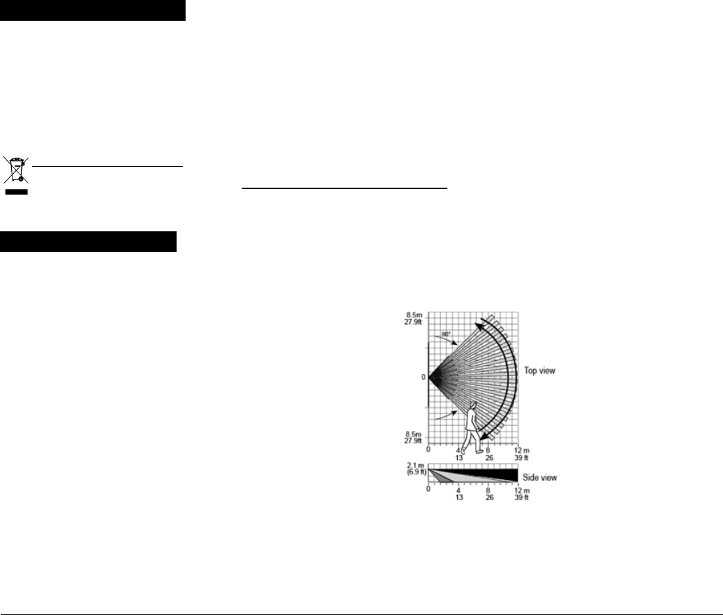
Figure 12 – Coverage Pattern
Walk Test
Max. coverage 12 x 12 m (39 x 39 ft) / 90°
Pet Immunity Up to 38 kg (85 lb)
D-306133 MP-802 K9-85 PG2 Installation Instructions 6

ELECTRICAL
Power Supply Type C.
Internal Battery 3V Lithium battery, type CR-123A. For UL installations, use Panasonic and GP only
Nominal Battery
Capacity
1450 mAh
Battery Life (typical use) 6 to 8 years
Low Battery Threshold 2.4 V
Note: Inability to connect with wireless network, or wireless link quality no higher than 20% may significantly reduce the
expected battery life
Battery Power Test Performed immediately upon battery insertion and periodically after every several hours.
The power supply is type C in accordance with EN 50131-6 Documentation – Clause 6.
FUNCTIONALITY
True Motion Event
Verification
2 remote selections at panel – LOW, HIGH
Alarm Period 2 seconds
LED Switch LED Enable (red LED lights for 2 sec. upon alarm detection)
WIRELESS
Frequency Europe and rest of world: 433-434, 868-869 USA: 912-919
Note: Only devices in frequency band 915 MHz are UL/ULC listed
Communication Protocol PowerG
Supervision Signaling at 4-min. intervals
Tamper Alert Reported when a tamper event occurs and in any subsequent message, until the tamper switch is restored
MOUNTING
Height 1.8-2.4 m (6 - 8 ft.). For pet rejection, the optimal height is 2.1 m (7 ft.) for a detection distance in a room up to 9 m (29.5
ft.) and at height 2.4 m (8 ft.) for a detection distance in a room between 9 – 12 m (29.5 – 39 ft.)
Installation Options Surface or corner
ENVIRONMENTAL
RF Immunity 20 V/m up to 1000 MHz, 10 V/m up to 2700 MHz
Operating Temperatures -10°C to 50°C (14°F to 122°F)
Storage Temperatures -20°C to 60°C (-4°F to 140°F)
Humidity Average relative humidity of up to approximately 75% non-condescending. For 30 days per year the relative humidity
may vary between 85% and 95% non-condescending.
For UL installations: 5 % to 93 % with no condensation
PHYSICAL
Size (H x W x D) 83 x 61 x 42 mm (3.27 x 2.4 x 1.66")
Weight (with battery) 90 g (3.17 oz)
Color White
PATENTS U.S. Patents 5,693,943 ● 6,211,522
WARRANTY
Visonic Limited (the “Manufacturer") warrants this product only (the "Product") to the original purchaser only (the
“Purchaser”)against defective workmanship and materials under normal use of the Product for a period of twelve
(12) months from the date of shipment bythe Manufacturer.
ThisWarrantyis absolutelyconditionalupon the Product having been properly installed, maintained and operated
under conditions of normal use in accordance with the Manufacturers recommended installation and operation
instructions. Products which have become defective for any other reason, according to the Manufacturers
discretion, such as improper installation, failure to follow recommended installation and operational instructions,
neglect, willful damage, misuse or vandalism, accidental damage, alteration or tampering, or repair by anyone
otherthan the manufacturer, are not covered by thisWarranty.
The Manufacturer does not represent that this Product may not be compromised and/or circumvented or that the
Product willprevent anydeath and/or personalinjury and/or damage to property resulting from burglary, robbery,
fire or otherwise, or that the Product will in allcases provide adequate warning or protection. The Product, properly
installed and maintained, onlyreducesthe riskof such events without warning and it isnot a guarantee or insurance
that such events willnot occur.
THIS WARRANTY IS EXCLUSIVE AND EXPRESSLY IN LIEU OF ALL OTHER WARRANTIES, OBLIGATIONS
OR LIABILITIES, WHETHER WRITTEN, ORAL, EXPRESS OR IMPLIED, INCLUDING ANY WARRANTY OF
MERCHANTABILITY OR FITNESS FOR A PARTICULAR PURPOSE, OR OTHERWISE. IN NO CASE SHALL
THE MANUFACTURER BE LIABLE TO ANYONE FOR ANY CONSEQUENTIAL OR INCIDENTAL DAMAGES
FOR BREACH OF THIS WARRANTY OR ANY OTHER WARRANTIES WHATSOEVER, AS AFORESAID.
THE MANU FACTURER SHALL I N NO EVENT BE LI ABLE FOR ANY SPECIAL, IND IRECT, IN CIDENTA L,
CONSEQUEN TIAL OR PUNITIVE DAMAGES O R FOR LOSS, DAMAGE, OR EXPENSE, INCLU DING LOSS
OF USE, PR OF I TS, REVEN U E, O R G OOD W ILL, D I RE C TL Y O R IN D IR E CT L Y A RI S IN G F R OM
PURCHASER’S USE OR INABILITY TO USE THE PRODUCT, OR FOR LOSS OR DESTRUCTION OF OTHER
PROPERTY O R FRO M AN Y OTH ER CA USE, EVEN IF MA NUFAC TURER HAS BEEN ADVI SED O F TH E
POSSIBILITY OF SUCH DAMAGE.
THE M ANUF ACTUR ER SHALL HAVE NO LIABI LITY FOR ANY DEAT H, PER SONA L AND/ OR B ODIL Y
IN JU R Y A ND/ OR DA M AG E T O PRO PER TY OR OTH ER L OSS WH ET H ER DI R EC T, I ND I REC T,
INCIDENTAL, CONSEQUENTIAL OR OTHERWISE, BASED ON A CLAIM THAT THE PRODUCT FAILED T O
FUNCTION.
However, if the Manufacturer is held liable, whether directly or indirectly, for any loss or damage arising under this
limited warranty, THE MANUFACTURER’S MAXIMUM LIABILITY (IF ANY) SHALL NOT IN ANY CASE EXCEED
THE PURCHASE PRICE OF THE PRODUCT, which shall be fixed as liquidated damages and not asa penalty, and
shallbe the complete and exclusive remedy against the Manufacturer.
When accepting the deliveryof the Product, the Purchaser agrees to the said conditions of sale and warranty and he
recognizeshaving been informed of.
Some jurisdictions do not allow the exclusion or limitation of incidental or consequentialdamages, so these limitations
maynot apply under certain circumstances.
The Manufacturer shall be under no liability whatsoever arising out of the corruption and/or malfunctioning of any
telecommunication or electronic equipment or any programs.
The Manufacturers obligations under this Warranty are limited solely to repairand/or replace at the Manufacturer’s
discretion any Product or part thereof that may prove defective. Any repair and/or replacement shallnot extend the
original Warranty period. The Manufacturer shall not be responsible for dismantling and/or reinstallation costs. To
exercise this Warranty the Product must be returned to the Manufacturer freight pre-paid and insured. Allfreight and
insurance costsare the responsibility of the Purchaser and are not included in this Warranty.
Thiswarranty shall not be modified, varied orextended, and the Manufacturer doesnot authorize any person to act
on itsbehalf in the modification, variation or extension of thiswarranty. This warranty shall applyto the Product only. All
products, accessories or attachments of others used in conjunction with the Product, including batteries, shall be
covered solelyby their own warranty, if any. The Manufacturer shallnot be liable for any damage or loss whatsoever,
whether directly, indirectly, incidentally, consequentiallyor otherwise, caused by the malfunction of the Product due to
products, accessories, or attachments of others, including batteries, used in conjunction with the Products. This
Warranty isexclusive to the originalPurchaserand is not assignable.
ThisWarrantyisin addition to and does not affect yourlegalrights. Any provision in this warranty which iscontraryto the
Law in the state or countrywere the Product issupplied shall not apply.
Warning: The user must follow the Manufacturer’s installation and operational instructions including testing the
Product and its whole system at least once a week and to take all necessary precautionsfor his/her safety and the
protection of his/her property.
1/08
Email: info@visonic.com
Internet: www.visonic.com
© VISONIC LTD. 2016 MP-802 K9-85 PG2 D-306133 (Rev.1 8/16)
D-306133 MP-802 K9-85 PG2 Installation Instructions 7