Visonic MP841 PIR detector with ZigBee protocol User Manual
Visonic Ltd. PIR detector with ZigBee protocol Users Manual
UserManual.wiki
>
Visonic
>
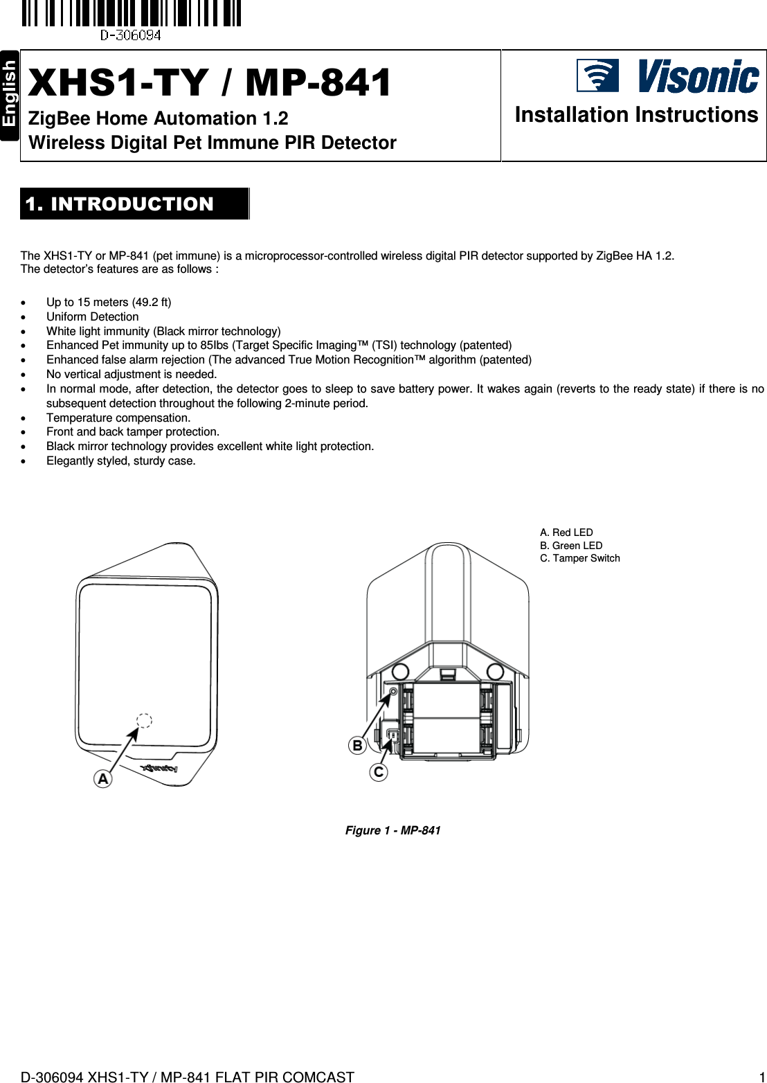
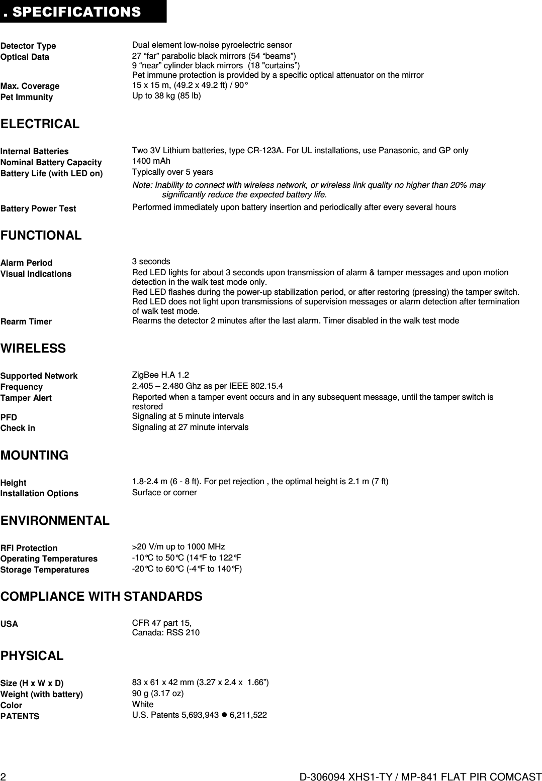
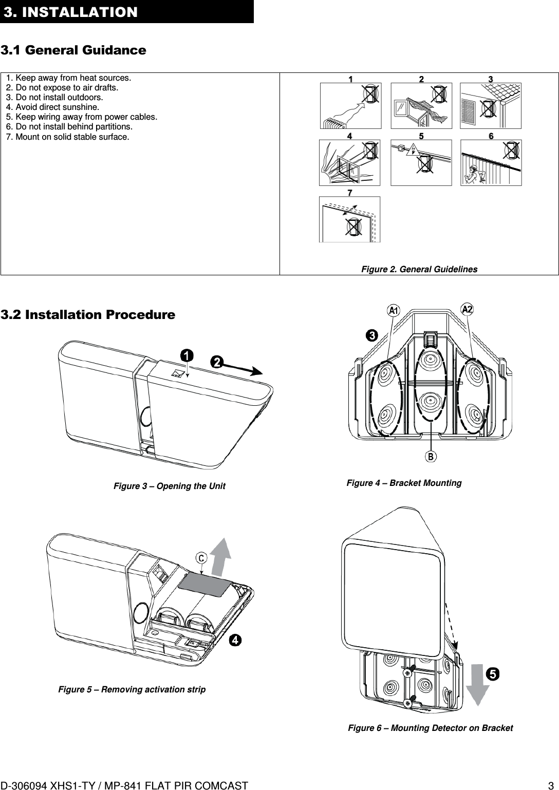
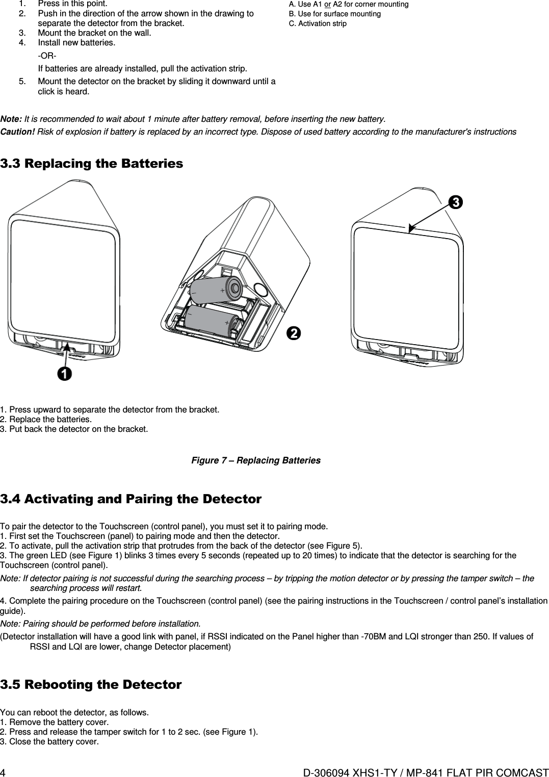
MP841 User Manual
>
Users Manual
Contents
1.
Users Manual
2.
User manual
Users Manual
Navigation menu
Upload a User Manual
Namespaces
Wiki Guide
HTML
PDF
Info
Views
User Manual
Discussion / Help
Navigation