Visonic MP841 PIR detector with ZigBee protocol User Manual
Visonic Ltd. PIR detector with ZigBee protocol Users Manual
Visonic >
Contents
- 1. Users Manual
- 2. User manual
Users Manual
D-306094 XHS1-TY / MP-841 FLAT PIR COMCAST 1
XHS1-TY / MP-841
ZigBee Home Automation 1.2
Wireless Digital Pet Immune PIR Detector
Installation Instructions
1. INTRODUCTION
The XHS1-TY or MP-841 (pet immune) is a microprocessor-controlled wireless digital PIR detector supported by ZigBee HA 1.2.
The detector’s features are as follows :
• Up to 15 meters (49.2 ft)
• Uniform Detection
• White light immunity (Black mirror technology)
• Enhanced Pet immunity up to 85Ibs (Target Specific Imaging™ (TSI) technology (patented)
• Enhanced false alarm rejection (The advanced True Motion Recognition™ algorithm (patented)
• No vertical adjustment is needed.
• In normal mode, after detection, the detector goes to sleep to save battery power. It wakes again (reverts to the ready state) if there is no
subsequent detection throughout the following 2-minute period.
• Temperature compensation.
• Front and back tamper protection.
• Black mirror technology provides excellent white light protection.
• Elegantly styled, sturdy case.
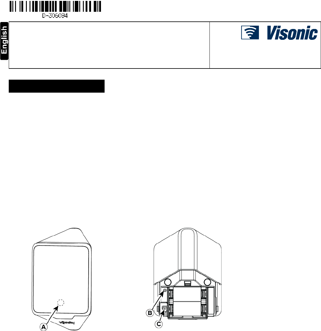
Figure 1 - MP-841
A. Red LED
B. Green LED
C. Tamper Switch

2 D-306094 XHS1-TY / MP-841 FLAT PIR COMCAST
. SPECIFICATIONS
Detector Type Dual element low-noise pyroelectric sensor
Optical Data 27 “far” parabolic black mirrors (54 “beams”)
9 “near” cylinder black mirrors (18 "curtains”)
Pet immune protection is provided by a specific optical attenuator on the mirror
Max. Coverage 15 x 15 m, (49.2 x 49.2 ft) / 90°
Pet Immunity Up to 38 kg (85 lb)
ELECTRICAL
Internal Batteries Two 3V Lithium batteries, type CR-123A. For UL installations, use Panasonic, and GP only
Nominal Battery Capacity 1400 mAh
Battery Life (with LED on) Typically over 5 years
Note: Inability to connect with wireless network, or wireless link quality no higher than 20% may
significantly reduce the expected battery life.
Battery Power Test Performed immediately upon battery insertion and periodically after every several hours
FUNCTIONAL
Alarm Period 3 seconds
Visual Indications Red LED lights for about 3 seconds upon transmission of alarm & tamper messages and upon motion
detection in the walk test mode only.
Red LED flashes during the power-up stabilization period, or after restoring (pressing) the tamper switch.
Red LED does not light upon transmissions of supervision messages or alarm detection after termination
of walk test mode.
Rearm Timer Rearms the detector 2 minutes after the last alarm. Timer disabled in the walk test mode
WIRELESS
Supported Network ZigBee H.A 1.2
Frequency 2.405 – 2.480 Ghz as per IEEE 802.15.4
Tamper Alert Reported when a tamper event occurs and in any subsequent message, until the tamper switch is
restored
PFD Signaling at 5 minute intervals
Check in Signaling at 27 minute intervals
MOUNTING
Height 1.8-2.4 m (6 - 8 ft). For pet rejection , the optimal height is 2.1 m (7 ft)
Installation Options Surface or corner
ENVIRONMENTAL
RFI Protection >20 V/m up to 1000 MHz
Operating Temperatures -10°C to 50°C (14°F to 122°F
Storage Temperatures -20°C to 60°C (-4°F to 140°F)
COMPLIANCE WITH STANDARDS
USA CFR 47 part 15,
Canada: RSS 210
PHYSICAL
Size (H x W x D) 83 x 61 x 42 mm (3.27 x 2.4 x 1.66”)
Weight (with battery) 90 g (3.17 oz)
Color White
PATENTS U.S. Patents 5,693,943 6,211,522
D-306094 XHS1-TY / MP-841 FLAT PIR COMCAST 3
3. INSTALLATION
3.1 General Guidance
1. Keep away from heat sources.
2. Do not expose to air drafts.
3. Do not install outdoors.
4. Avoid direct sunshine.
5. Keep wiring away from power cables.
6. Do not install behind partitions.
7. Mount on solid stable surface.
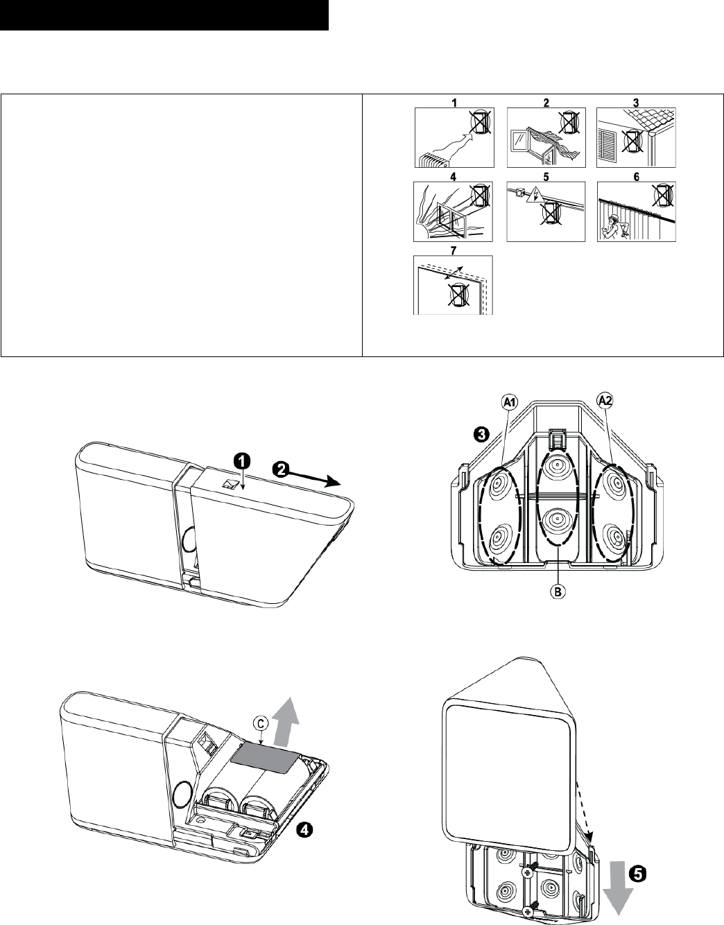
Figure 2. General Guidelines
3.2 Installation Procedure
Figure 3 – Opening the Unit Figure 4 – Bracket Mounting
Figure 5 – Removing activation strip
Figure 6 – Mounting Detector on Bracket
4 D-306094 XHS1-TY / MP-841 FLAT PIR COMCAST
1. Press in this point.
2. Push in the direction of the arrow shown in the drawing to
separate the detector from the bracket.
3. Mount the bracket on the wall.
4. Install new batteries.
-OR-
If batteries are already installed, pull the activation strip.
5. Mount the detector on the bracket by sliding it downward until a
click is heard.
A. Use A1 or A2 for corner mounting
B. Use for surface mounting
C. Activation strip
Note: It is recommended to wait about 1 minute after battery removal, before inserting the new battery.
Caution! Risk of explosion if battery is replaced by an incorrect type. Dispose of used battery according to the manufacturer's instructions
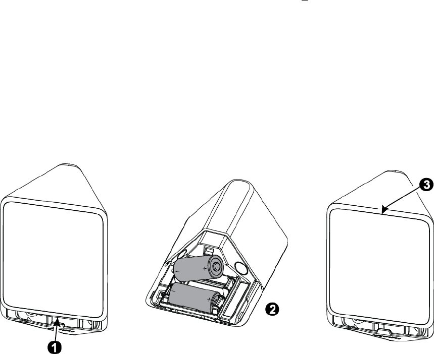
3.3 Replacing the Batteries
1. Press upward to separate the detector from the bracket.
2. Replace the batteries.
3. Put back the detector on the bracket.
Figure 7 – Replacing Batteries
3.4 Activating and Pairing the Detector
To pair the detector to the Touchscreen (control panel), you must set it to pairing mode.
1. First set the Touchscreen (panel) to pairing mode and then the detector.
2. To activate, pull the activation strip that protrudes from the back of the detector (see Figure 5).
3. The green LED (see Figure 1) blinks 3 times every 5 seconds (repeated up to 20 times) to indicate that the detector is searching for the
Touchscreen (control panel).
Note: If detector pairing is not successful during the searching process – by tripping the motion detector or by pressing the tamper switch – the
searching process will restart.
4. Complete the pairing procedure on the Touchscreen (control panel) (see the pairing instructions in the Touchscreen / control panel’s installation
guide).
Note: Pairing should be performed before installation.
(Detector installation will have a good link with panel, if RSSI indicated on the Panel higher than -70BM and LQI stronger than 250. If values of
RSSI and LQI are lower, change Detector placement)
3.5 Rebooting the Detector
You can reboot the detector, as follows.
1. Remove the battery cover.
2. Press and release the tamper switch for 1 to 2 sec. (see Figure 1).
3. Close the battery cover.
D-306094 XHS1-TY / MP-841 FLAT PIR COMCAST 5
3.6 Defaulting the Detector
CAUTION! The defaulting process removes the device from the network and enables re-pairing.
Separate the detector from the bracket to remove both batteries. (see Figure 7).
1. Press and hold down the detector’s tamper switch.
2. Insert one of the two batteries into the detector while observing battery polarity.
3. Release the tamper switch within 4 seconds (the LED blinks 3 times every 5 seconds).
4. To re-pair the detector, follow the instructions in section 3.4.
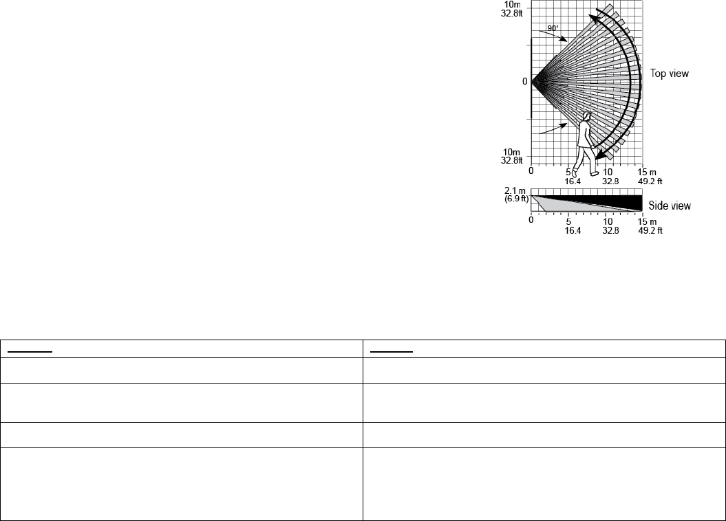
3.7 Walk Testing
Walk across the far end of coverage pattern in both directions. The LED should light for 2-3
seconds each time your motion is detected.
Important! Instruct the user to walk test at least once a week to verify proper function of the
detector.
Note: Upon battery insertion or closing the cover (which results in closing the tamper switch)
the LED flashes for 2 minutes and the detector goes into walk-test mode for 15
minutes. In walk-test mode the LED lights upon every motion detection. After 15
minutes the detector automatically enters normal mode in which the LED will not
blink after detection.
Figure 8 - Coverage Pattern Walk-Test
TROUBLESHOOTING
If you encounter one of the following problems with the MP-841, perform the suggested remedy:
Problem
Remedy
Attempt to pair the sensor is unsuccessful. Make sure that the sensor has been defaulted and is set to pairing
mode (see section 3.4).
The sensor and the Touchscreen (panel) do not communicate. Perform the signal strength testing procedure described in the control
panel installation manual. Make sure that the signal is sufficient. If
necessary, replace the sensor’s battery.
The sensor sends a Low Battery indication. To ensure continuous proper operation, replace both batteries within
two weeks of the first Low Battery indication.
Panel does not arm because of an unrecognized sensor malfunction Consult with your installer or system provider before you disable
a zone.
Disable the sensor zone (see the control panel user manual). Note that
disabling a sensor zone lowers the overall security level of your
system.
6 D-306094 XHS1-TY / MP-841 FLAT PIR COMCAST
SPECIAL COMMENTS
Even the most sophisticated detectors can sometimes be defeated or may fail to warn due to: DC power failure / improper connection, malicious
masking of the lens, tampering with the optical system, decreased sensitivity in ambient temperatures close to that of the human body and
unexpected failure of a component part.
The above list includes the most common reasons for failure to detect intrusion, but is by no means comprehensive. It is therefore recommended
that the detector and the entire alarm system be checked weekly, to ensure proper performance.
An alarm system should not be regarded as a substitute for insurance. Home and property owners or renters should be prudent enough to
continue insuring their lives and property, even though they are protected by an alarm system.
This device has been tested and found to comply with the limits for a Class B digital device, pursuant to Part 15 of the FCC Rules. These limits
are designed to provide reasonable protection against harmful interference in residential installations. This equipment generates, uses and can
radiate radio frequency energy and, if not installed and used in accordance with the instructions, may cause harmful interference to radio and
television reception. However, there is no guarantee that interference will not occur in a particular installation. If this device does cause such
interference, which can be verified by turning the device off and on, the user is encouraged to eliminate the interference by one or more of the
following measures:
Re-orient or re-locate the receiving antenna.
Increase the distance between the device and the receiver.
Connect the device to an outlet on a circuit different from the one that supplies power to the receiver.
Consult the dealer or an experienced radio/TV technician.
Even the most sophisticated detectors can sometimes be defeated or may fail to warn due to: DC power failure / improper connection, malicious
masking of the lens, tampering with the optical system, decreased sensitivity in ambient temperatures close to that of the human body and
unexpected failure of a component part.
COMPLIANCE WITH STANDARDS
FCC
This device complies with Part 15 of the FCC Rules and RSS-210 of Industry and Science Canada. Operation is subject to the following two
conditions: (1) This device may not cause harmful interference, and (2) this device must accept any interference received, including interference
that may cause undesired operation.
This device complies with Industry Canada license-exempt RSS standard(s). Operation is subject to the following two conditions: (1) this device
may not cause interference, and (2) this device must accept any interference, including interference that may cause undesired operation of the
device.
Le présent appareil est conforme aux CNR d'Industrie Canada applicables aux appareils radio exempts de licence. L'exploitation est autorisée
aux deux conditions suivantes : (1) l'appareil ne doit pas produire de brouillage, et (2) l'utilisateur de l'appareil doit accepter tout brouillage
radioélectrique subi, même si le brouillage est susceptible d'en compromettre le fonctionnement.
WARNING! Changes or modifications to this unit not expressly approved by the party responsible for compliance could void the user’s authority to
operate the equipment.
To comply with FCC Section 1.1310 for human exposure to radio frequency electromagnetic fields and IC requirements, implement the following
instruction: A distance of at least 20cm. between the equipment and all persons should be maintained during the operation of the equipment.
Europe (CE): EN 300328, EN 301489, EN 60950, EN 50130-4, EN 50131-1,
The MP-840 is compatible with the RTTE requirements - Directive 1999/5/EC of the European Parliament and of the Council of 9 March 1999
USA: CFR 47 Part 15
Canada: RSS 210
EMAIL: info@visonic.com
INTERNET: www.visonic.com
VISONIC LTD. 2016 XHS1-TY / MP-841 FLAT PIR COMCAST D-306094 ( Rev. 0, 04/16)