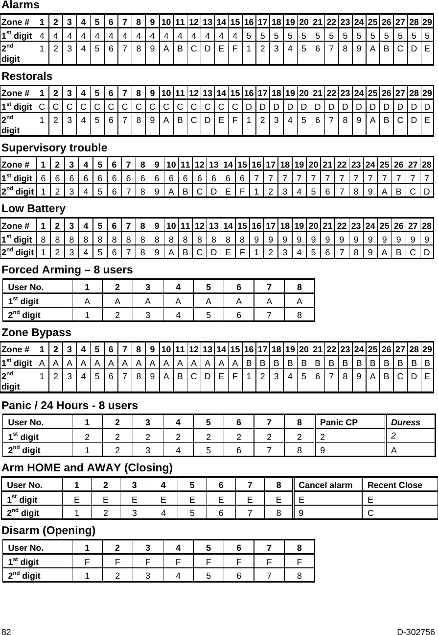
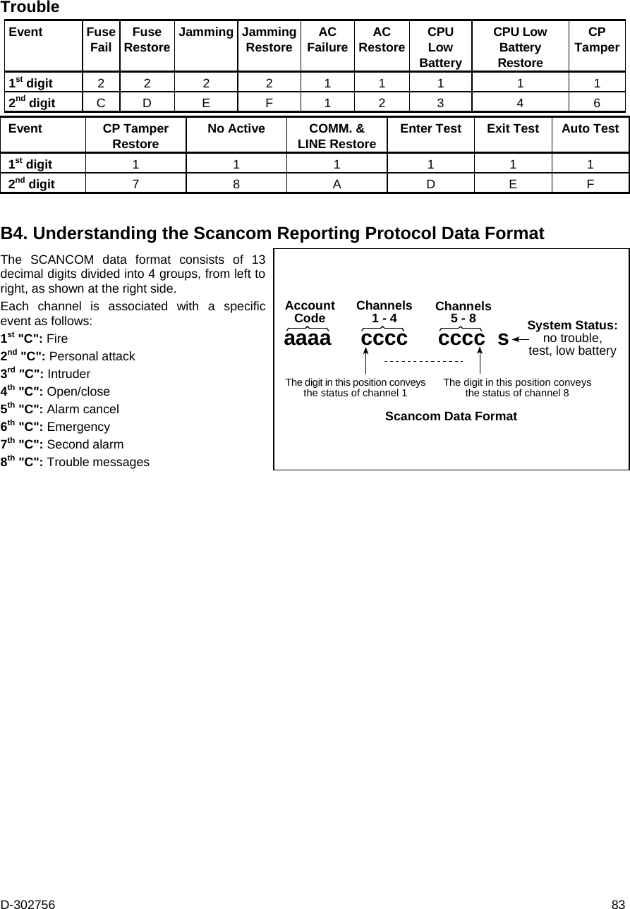
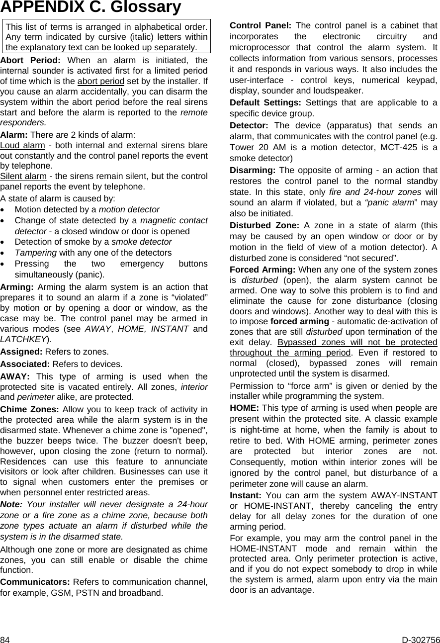
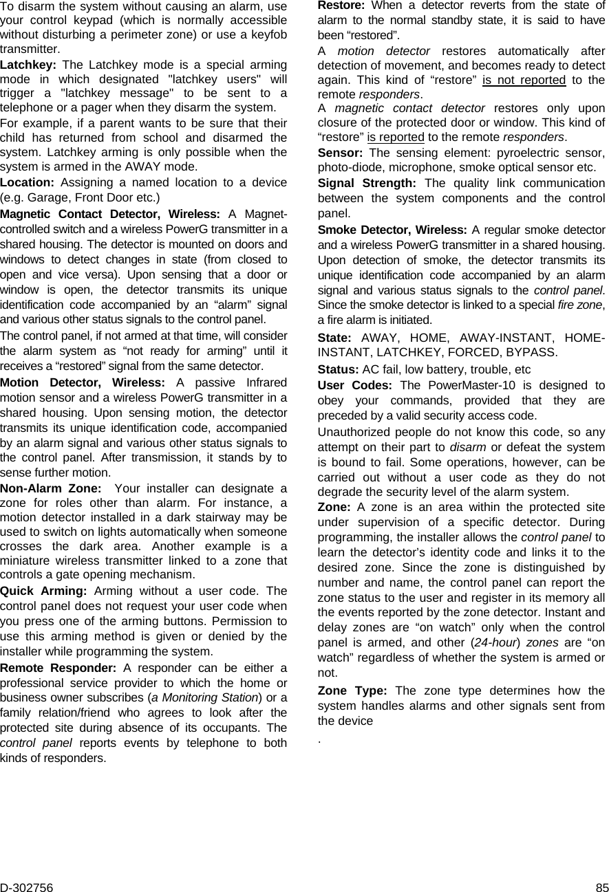
Visonic PMASTER10G2 Burglar alarm control panel User Manual User manual 21096
Visonic Ltd. Burglar alarm control panel User manual 21096
UserManual.wiki
>
Visonic
>
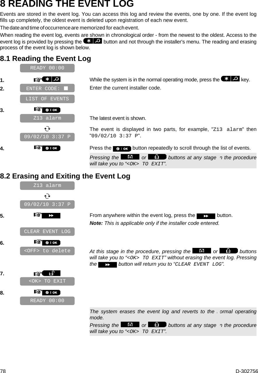
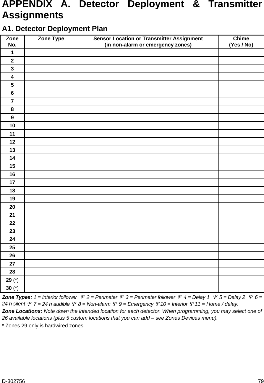
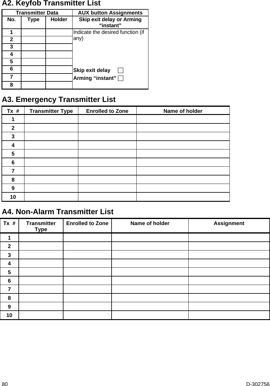
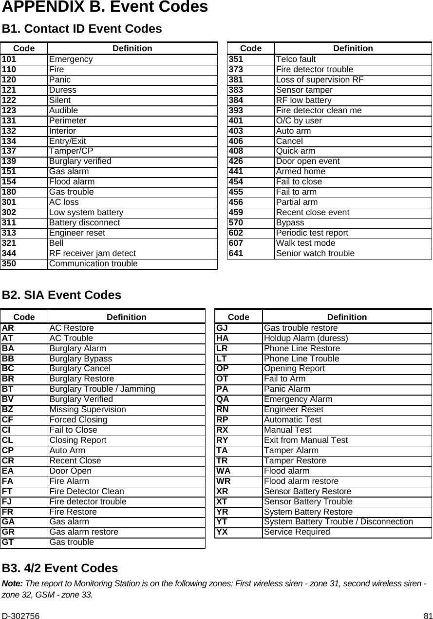
PMASTER10G2 User Manual
manual
Navigation menu
Upload a User Manual
Namespaces
Wiki Guide
HTML
PDF
Info
Views
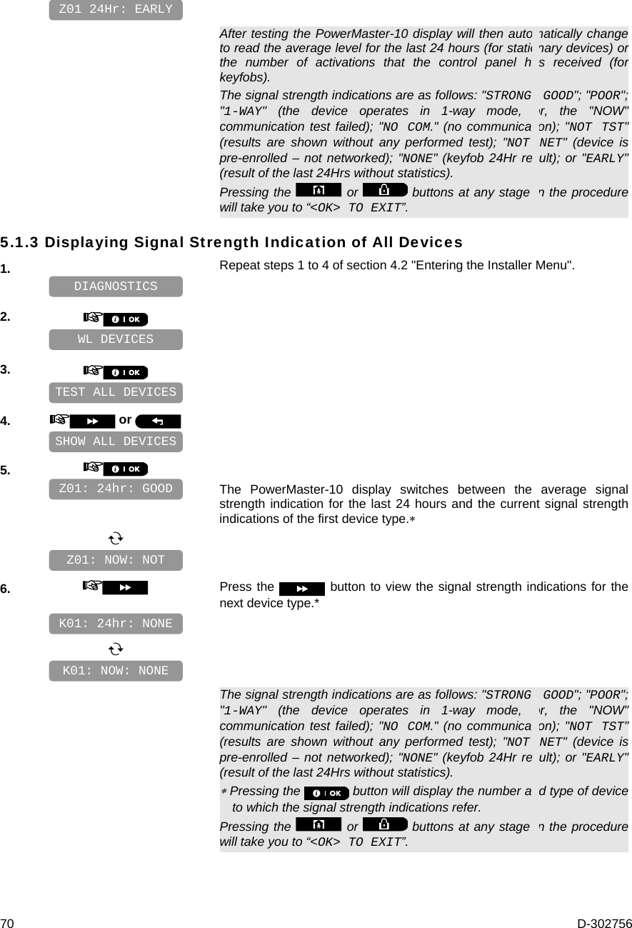
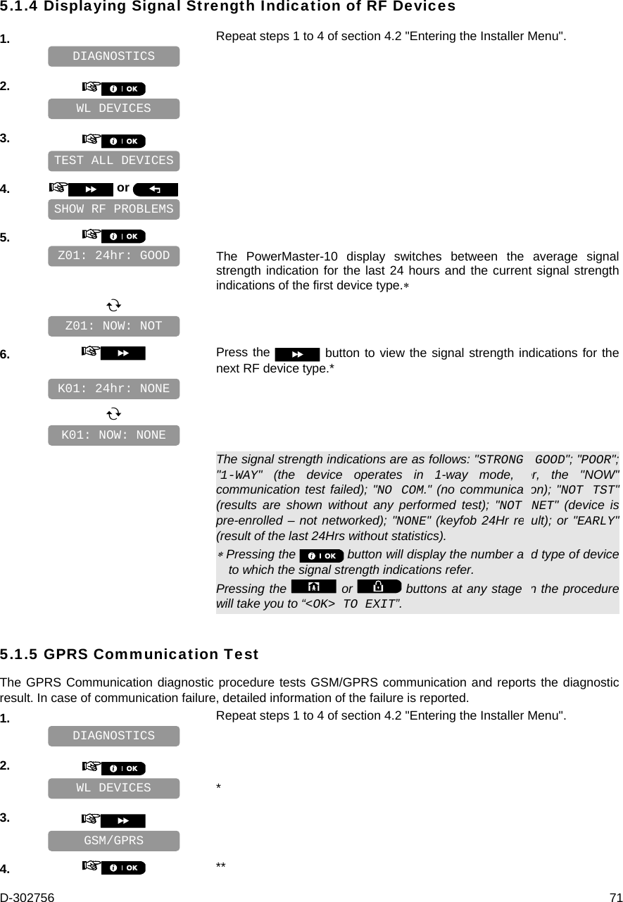
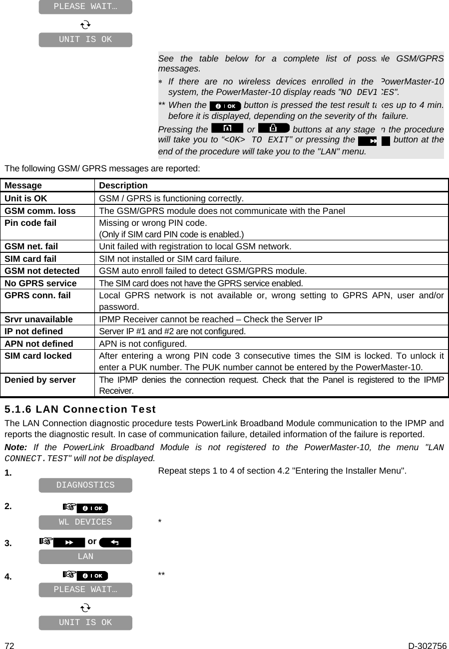
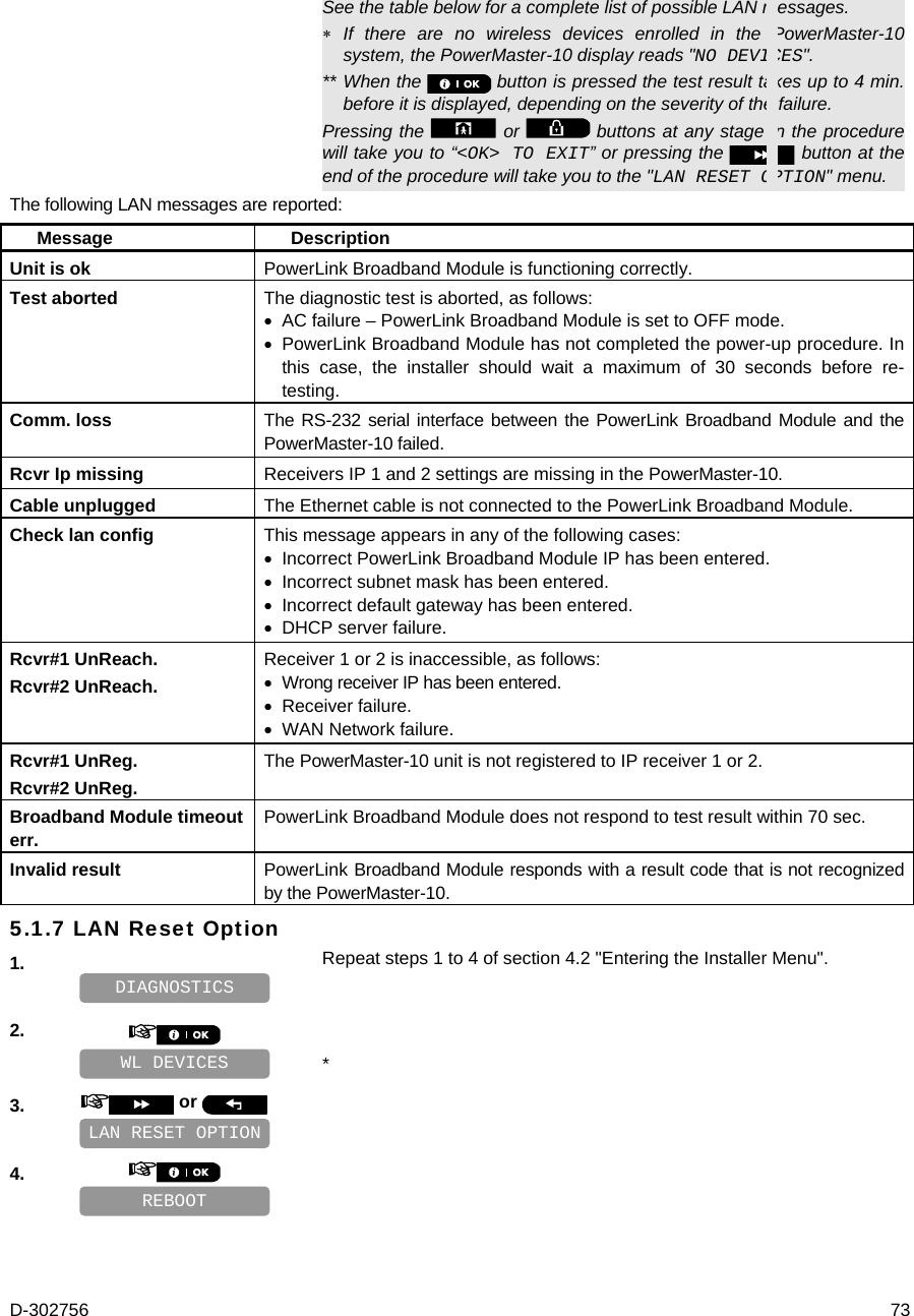
User Manual
Discussion / Help
Navigation