Visonic PMASTER10G2 Burglar alarm control panel User Manual User manual 21096
Visonic Ltd. Burglar alarm control panel User manual 21096
Visonic >
manual
D-302756 1
PowerMaster-10 Installer Guide
TABLE OF CONTENTS
1. INTRODUCTION .......................................................4
PowerG Technology is easy to install and
maintain ................................................................4
2. SPECIFICATIONS.....................................................5
Functional.............................................................5
Wireless ................................................................6
Electrical...............................................................6
Communication....................................................6
Physical Properties .............................................7
Peripherals and Accessory Devices..................7
3. INSTALLATION.........................................................7
3.1 Choosing the Mounting Location ................7
3.2 Mounting the Unit ..........................................8
Opening the Control Panel and Bracket
Mounting..............................................................8
Closing the Control Panel..................................8
3.3 Supplying Power to the Unit.........................9
Inserting Backup Battery ...................................9
Connecting Power to Panel.............................10
3.4 Connecting to the Telephone Line.............10
3.5 System Planning & Programming..............12
3.6 Extension Modules GSM Installation.........12
PowerLink Broadband Module Installation....12
3.7 Annual System Check.................................13
4. PROGRAMMING.....................................................14
4.1 General Guidance........................................14
4.2 Entering the Installer Menu ........................14
Installer Mode Options Menu..........................14
Programming User Settings............................15
4.3 Navigation.....................................................16
4.4 Permissions and User Codes.....................16
4.4.1 Setting a New Installer Code.................16
4.4.2 Setting the Master Installer Code.........17
4.4.3 Setting User Codes................................ 18
4.4.4 Enabling User Permit for Installer
Access............................................................... 18
4.4.5 Configuring Permissions for System
Reset after Alarm Event.................................. 18
4.4.6 Configuring a Duress Code.................. 19
4.5 Zones / Devices........................................... 20
4.5.1 General Guidance.................................. 20
4.5.2 Adding a Wireless Device..................... 20
4.5.3 Adding Wired Zones.............................. 24
4.5.4 Deleting a Device................................... 25
4.5.5 Modifying a Device ................................ 26
4.5.6 Replacing a Device................................ 27
4.5.7 Defining Defaults.................................... 28
4.6 Siren Configuration .................................... 29
4.6.1 Configuring the Length of Time the Bell
is allowed to Function...................................... 29
4.6.2 Enabling the Internal Siren ................... 29
4.6.3 Configuring the Period of Strobe Light
Activation .......................................................... 30
4.6.4 Enabling Siren Activation upon
Telephone Line Failure ................................... 30
4.7 Event Reporting Configuration ................. 31
4.7.1 General.................................................... 31
4.7.2 Setup Report Communicators.............. 31
4.7.3 Configuring Event Reporting to
Monitoring Station............................................ 34
4.7.4 Configuring Event Reporting to Users.43
4.8 Security System Configuration ................. 46
4.8.1 Enable Cross Zoning............................. 46
4.8.2 Configuring Swinger Stop..................... 47
4.8.3 Enable Monitoring of Activity at Home 47
4.8.4 Configuring Alarm Cancel Period ........ 48
4.8.5 Configuring Power Failure Threshold
Period ................................................................ 48
4.8.6 Configuring Abort Time ......................... 49
4.8.7 Configuring a Confirmed Alarm............ 50
4.8.8 Enable Alarm upon Detection of
Jammed or Missing Device ............................ 50
4.8.9 Configuring the Jamming Detection .... 51
4.8.10 Configuring Whether a Missing Device
Causes the System to Become "NOT READY"
............................................................................ 51
4.8.11 Configuring the Time Period by which a
Device is considered Missing......................... 52
2 D-302756
4.9 Arming/Disarming Options And Exit/Entry
Delay ...................................................................53
4.9.1 Configuring Exit Modes......................... 53
4.9.2 Configuring Entry Delays Duration ...... 53
4.9.3 Configuring Exit Delay Duration........... 54
4.9.4 Enabling Quick Arm............................... 54
4.9.5 Configuring Bypassing Zones .............. 55
4.9.6 Configuring Panic Alarm Activation..... 56
4.9.7 Enabling Latchkey Arming.................... 56
4.10 User Interface Customization...................57
4.10.1 Enabling Trouble Beeps...................... 57
4.10.2 Enabling Piezo Beeps......................... 57
4.10.3 Enabling the Back Light ...................... 58
4.10.4 Configuring the Disarm Option........... 58
4.10.5 Configuring the Screen Saver Options
............................................................................ 59
4.10.6 Enabling the Memory Prompt............. 60
4.10.7 Enabling Keyfob Low Battery
Acknowledgement ........................................... 60
4.11 DEFINE CUSTOM LOCATIONS.................61
4.12 CONFIGURING OUTPUT PARAMETERS.61
4.12.1 Preliminary Guidance.......................... 61
4.12.2 Define PGM .......................................... 62
4.13 Configuring Remote Programming Access
Permissions........................................................66
5 DIAGNOSTIC TEST ................................................ 68
5.1 Testing Devices ...........................................68
5.1.1 Testing all Devices................................. 68
5.1.2 Testing One Device ............................... 69
5.1.3 Displaying Signal Strength Indication of
All Devices........................................................ 70
5.1.4 Displaying Signal Strength Indication of
RF Devices ....................................................... 71
5.1.5 GPRS Communication Test ................. 71
5.1.6 LAN Connection Test ............................ 72
5.1.7 LAN Reset Option.................................. 73
6 CALLING UPLOAD/DOWNLOAD SERVER....... 74
7. MAINTENANCE ......................................................75
7.1 Handling System Troubles ........................ 75
7.2 Dismounting the Control Panel................. 76
7.3 Replacing the Backup Battery................... 76
7.4 Fuse Replacement ...................................... 76
7.5 Replacing/Relocating Detectors................ 77
7.6 Restoring Factory Defaults........................ 77
7.7 Viewing the Serial Number ........................ 77
8 READING THE EVENT LOG..................................78
8.1 Reading the Event Log............................... 78
8.2 Erasing and Exiting the Event Log ........... 78
APPENDIX A. Detector Deployment & Transmitter
Assignments...............................................................79
A1. Detector Deployment Plan ........................ 79
A2. Keyfob Transmitter List............................. 80
A3. Emergency Transmitter List...................... 80
A4. Non-Alarm Transmitter List....................... 80
APPENDIX B. Event Codes......................................81
B1. Contact ID Event Codes............................. 81
B2. SIA Event Codes......................................... 81
B3. 4/2 Event Codes.......................................... 81
B4. Understanding the Scancom Reporting
Protocol Data Format ....................................... 83
APPENDIX C. Glossary.............................................84
APPENDIX D. DEFAULT AND PROGRAMMED
ZONE DEFINITIONS...................................................86

D-302756 3
MESSAGE TO THE INSTALLER
The PowerMaster-10 control panel is supplied with 3 instruction manuals:
Installer Guide (this manual - for your exclusive use)
User’s Guide (for your use during installation only - Must be handed over to the master user after testing the
system)
Accessories Guide (includes a full description of devices that are supported by the PowerMaster-10 system)
Appendices A.1 and A.2 of the Installer Guide will help you prepare an installation plan. Please take time to fill
out the forms - your job will become much easier and confusion will be prevented. Filling out the forms will also
help you create a list of detectors and transmitters that must be obtained for the particular application.
Compatible detectors and transmitters are listed in the Accessories Guide.
Remember - it is advisable to power up the control panel temporarily after unpacking and program it on the work
bench, in accordance with the installation plan.
Although setting the correct time and date is one of the user tasks, we recommend that you set the time and
date in the course of programming. Access to the “User Settings” for the installer is possible through the
installer‘s menu or through the user menu (see User’s Guide section 2).
After programming, proceed to install the system as detailed in the Installation Instructions, from paragraph
Error! Reference source not found..
The installer should verify line seizure. Be aware of other phone line services such as DSL. If DSL service is
present on the phone line, you must install a filter. It is suggested to use the DSL alarm filter model Z-
A431PJ31X manufactured by Excelsus Technologies, or equivalent. This filter simply plugs into the RJ-31X jack
and allows alarm reporting without breaking the internet connection.
Compliance Statement
Hereby, Visonic Group declares that the PowerG series of central units and accessories are designed to comply
with:
U.S. Standards: USA: (FCC) CFR 47part 15 and part 68
Canada Standards: RSS 210
European CE Standards
The PowerMaster-10 is compatible with the RTTE requirements - Directive 1999/5/EC of the European Parliament
and of the Council of 9 March 1999.
According to the European standard EN50131-1, the PowerMaster-10 security grading is 2 – "low to medium risk"
and environmental classification is II – "indoor general" and the power supply type is A. EN 50131-6
GSM standards:
Europe: Complies with CE standards 3GPP TS 51.010-1, EN 301 511, EN301489-7
USA: CFR 47 Part 22 (GSM850) and Part 24 (GSM 1900).
EMC standard: CFR 47 Part 15
4 D-302756
1. INTRODUCTION
The PowerMaster-10 is a user and installer-friendly, 29-zone fully-supervised wireless control system using
Visonic's new revolutionary PowerG™ two-way Time Division Multiple Access (TDMA) Frequency Hopping
Spread Spectrum (FHSS) technology.
The system is designed to function in an appealing way to the user and also offers features that make installers’
life easier than ever before:
PowerG Technology is easy to install and maintain
Quick and easy installation and on-site diagnostics:
Choosing the ideal location to install a wireless device or testing it at a later stage can be very strenuous
and frustrating. With PowerMaster-10 there is no need to run back and forth to the panel to read the link
quality because PowerG devices have a quality link indicator built-into the device itself which enables
choosing the ideal location quickly and easily without using the panel. See Chapter 3.
Quick and easy on-site and remote configuration of sensors and system peripherals:
PowerMaster-10 devices (sensors, PIR cameras, sirens, keypads etc) can be configured from the control
panel or from remote locations (installation or monitoring company's offices) with the option for using
configurable defaults providing a collective device configuration.
This saves time since there is no need to travel to the installation site, to climb ladders and open devices.
See – Chapter 4.
Cost-saving advanced remote diagnostics and walk testing:
Many of the problems associated with wireless systems are due to invisible RF phenomena, such as
interferences, changes in the premises and unstable link quality. Having a professional diagnostic tool in
the RF network is critical for cost saving servicing of wireless alarm systems. The PowerMaster-10
performs continuous diagnostic tests on the RF environment and on interferences at the site and provides
you (locally and remotely) with pertinent information that helps you to understand and resolve the problems.
In addition, PowerMaster-10 provides you with remote real time testing and walk testing of the system sensors
and peripherals – saving you time and money in not needing to visit the site. See Chapter 5.
Main Benefits and Features:
Two-way communication ensures there are no lost alarms
Multiple channels (up to 50) and frequency hopping technology overcomes interferences to wireless
communication
Transmission range is by far greater than the industry standard (2000m, 6000ft), enabling repeater-
free installations even in large premises
Message collisions are eliminated by using the same technologies used in WiMAX, GSM and
Bluetooth
Devices dynamically start and stop using available repeaters according to need
Smart mechanism enables adjacent systems to co-exist without disturbing one another
Short keep-alive period provides reliable supervision of any vandalism attempts or device failure
Communication is protected by the proven AES-128 encryption algorithm to protect against
sophisticated intruders
Two-way communication eliminates all unnecessary re-transmissions
5-8 years battery life for all peripherals*
Minimum power consumption and "air pollution" due to:
- Adaptive transmission power which is determined according to the level of RF interferences
- Devices dynamically change wireless signal routing to utilize the most reliable communication
pathway available
All devices are configured from the panel – no hardware switches and no need to re-open the
peripherals once closed
7-digit code on each device is used for easy local or remote enrollment
Configuration templates enable to configure the devices collectively instead of individually
Special button on each device prevents RF activity from interfering with enrollment procedures
Wireless signal quality indication visible on all devices – enables to choose the ideal location for
installation without using the panel during mounting of peripherals
Powerful diagnostic tool indicates RF link quality to show abrupt problems and to verify installation in
house setup.
D-302756 5
Remotely review and/or change configuration and status of all peripherals
Initiate remote walk test with assistance by anyone in the house
Remote diagnostics of wireless signal quality for all peripherals - measure all wireless connections and
reports back
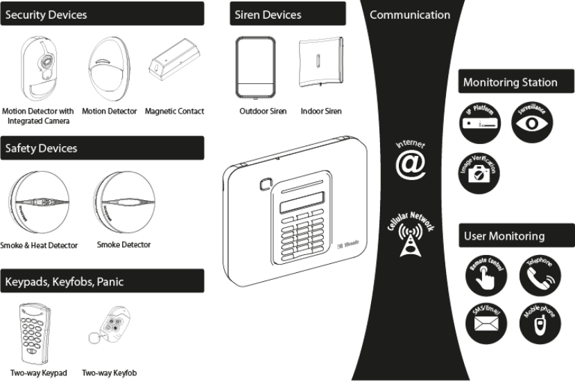
System Architecture:
2. SPECIFICATIONS
Functional
Zones Number 28 wireless zones, 1 hardwired input.
Hardwired Zone Requirements 2.2 kE.O.L. resistance (max. resistance of wires 220
Installer and User Codes 1 master installer (9999 by default)*
1 installer (8888 by default)*
1 master user, no. 1 (1111 by default)
Users nos. 2 - 8
* Codes must not be identical
Control Facilities - Integral keypad, wireless keyfobs and keypads
- SMS commands via optional GSM/GPRS module.
- Remote control by telephone.
Note: For SIA CP-01 compliance, when using KF-234 PG2 an external
siren must also be used.
Display Single line, backlit 16-large character LCD.
Arming Modes AWAY, HOME, AWAY-INSTANT, HOME-INSTANT, LATCHKEY,
FORCED, BYPASS.
Alarm Types Silent alarm, personal emergency alarm, burglary alarm and fire alarm.

6 D-302756
Siren Signals Continuous (intrusion / 24 hours / panic); triple pulse - pause - triple
pulse... (fire).
Siren (bell) Timeout Programmable (4 min. by default)
Internal Sounder Output At least 85 dBA at 10 ft (3 m)
Supervision Programmable time frame for inactivity alert
Special Functions - Chime zones
- Diagnostic test and event log.
- Local and Remote Programming over Telephone, GSM /GPRS connections.
- Calling for help by using an emergency transmitter.
- Tracking inactivity of elderly, physically handicapped and infirm people.
Data Retrieval Alarm memory, trouble, event log
Real Time Clock (RTC) The control panel keeps and displays time and date. This feature is also used
for the log file by providing the date and time of each event
Wireless
RF Network PowerG – 2-way synchronized Frequency Hopping (TDMA / FHSS)
Frequency bands (Mhz) 433 – 434 868 - 869 912 - 918
Hopping frequencies 8 4 50
Encryption AES-128
Electrical
External AC/AC adapter Europe: 230VAC 50Hz input, 9VAC 700mA output.
USA: 120VAC 60Hz input, 9VAC 1000mA output.
Internal AC/DC Switching power supply:
Input: 100-240V AC, 0.12 A Max.
Output: 7.5V DC, 1.2A Max.
Current Drain Approx. 70 mA standby, 1600 mA peak at full load.
Backup Battery Pack 4.8V 1300 mAh, rechargeable NiMH battery pack, p/n GP130AAM4YMX,
manufactured by GP or equivalent
Note: For compliance with UL standards the battery backup period shall
exceed 24 hours and 12 hours for compliance with CE standards.
Time to Charge 80 % ( 13 Hrs)
Optional Backup Battery Pack 4.8V 2200 mAh, rechargeable NiMH battery pack, p/n GP230AAHC4YMX,
manufactured by GP
Low Voltage Alarm 4.8V
Communication
Communication PSTN; GSM; GPRS; IP (for future use)
Built-in Modem 300 baud, Bell 103 protocol
Data Transfer to Local
Computer Via RS232 serial port
Report Destinations 2 Monitoring Stations, 4 private telephones
Reporting Format Options SIA, Pulse 4/2 1900/1400 Hz, Pulse 4/2 1800/2300 Hz, Contact ID,
Scancom, SIA IP, Visonic PowerNet.

D-302756 7
Pulse Rate 10, 20, 33 and 40 pps - programmable
Message to Private Phones Tone
Ring Detection The unit does not support ring detection without DC voltage present on the
telephone lines.
Physical Properties
Operating Temp. Range 14°F to 120°F (-10°C to 49°C)
Storage Temp. Range -4°F to 140°F (-20°C to 60°C)
Humidity 85% relative humidity, @ 30°C (86°F)
Size 196 x 180 x 55 mm (7-5/8 x 7 x 2 in.)
Weight 658g (23 Oz) (with battery)
Color White
Peripherals and Accessory Devices
Modules GSM/GPRS, IP (future use)
Additional wireless devices 30 detectors, 8 keyfobs, 2 keypads, 2 sirens, 4 repeaters
Wireless Devices and
peripherals (*):
(*) Visonic is currently developing
many more devices and
peripherals that will be available
during 2011.
Magnetic Contact: MC-302 PG2
Motion Detectors: Next PG2; Next K9 PG2
PIR Camera Detectors: Next CAM PG2; Next-K9 CAM PG2
Smoke Detector: SMD-426 PG2/ SMD-427 PG2
Keyfob: KF-234 PG2
Keypad: KP-140 PG2
Outdoor Siren: SR-730 PG2
Repeater: RP-610 PG2
3. INSTALLATION
3.1 Choosing the Mounting Location
To ensure the best possible mounting location of the PowerMaster-10 control panel, the following points should
be observed:
Mount the system approximately in the center of the installation site between all the transmitters
In close proximity to an AC source and a telephone line connection (if PSTN is used)
Far from sources of interference, such as:
Electrical noise and strong electromagnetic sources, such as computers, television, power conductors,
cordless phones, light dimmers, etc.
Large metal objects (such as metal doors and metal closets)
Note: A distance of at least 1 meter (3 ft) is recommended.
Make sure that the signal reception level for each transmitter's signal, shown during the Diagnostics test of
the PowerMaster-10, is "Strong" or "Good".
The alarm can be heard during HOME mode.
Wireless magnetic contacts should be installed in a vertical position and as high up the door or window as
possible.
Wireless detectors should be installed at the height specified in their Installation Instructions
Repeaters should be located high on the wall in mid-distance between the transmitters and the control
panel.
WARNING! To comply with FCC RF exposure compliance requirements, the control panel should be located at
a distance of at least 20 cm from all persons during normal operation. The antennas used for this product must
not be co-located or operated in conjunction with any other antenna or transmitter.
8 D-302756
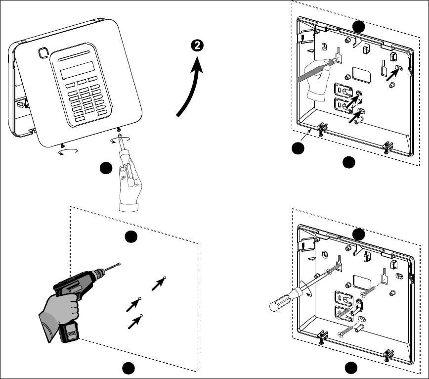
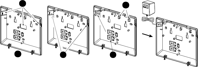
3.2 Mounting the Unit
Required tool: Philips screwdriver #2.
PowerMaster-10 mounting process is shown in Figure 3.1 - 3.2.
Opening the Control Panel and Bracket Mounting
4
3
5
1
A
A
A
B
A. Mounting surface
B. Back unit
To Mount the Unit:
1. Release the screws
2. Remove the front cover
3. Mark 4 drilling points on the mounting surface
4. Drill 4 holes and insert wall anchors
5. Fasten the back unit with 4 screws
Figure 3.1 – Back Unit Mounting
WARNING! When plugging SIREN & ZONE terminals back into place, be sure to align them carefully with the
pins on the PCB. Misaligned or reverse insertion of terminals may damage internal PowerMaster-10 circuits!
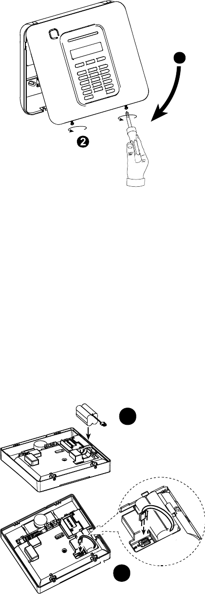
Closing the Control Panel
Control panel final closure is shown below.
D-302756 9
1
To Close the Control Panel:
1. Close the front cover
2. Fasten the screws
Figure 3.2 - Final Closure
3.3 Supplying Power to the Unit
Connect power to the PowerMaster-10 temporarily (see Figure 3.4). Alternatively, you may power up from the
backup battery, as shown in Figure 3.3.
Disregard any “trouble” indications pertaining to lack of battery or lack of telephone line connection.
For Europe Safety Compliance:
a. The model shall be installed according to the local electrical code.
b. The circuit breaker shall be readily accessible.
c. The rating of the external circuit breaker shall be 16A or less.
d. The cables for the AC mains connection shall have an overall diameter of 13mm and 16mm conduit.
Please refer to Figure 3.4 "Power Cable Connection".
Inserting Backup Battery
Connect battery pack as shown in the next drawing.
1
2
10 D-302756
1. Battery insertion
2. Battery connection
Figure 3.3 – Connecting Power to the Control Panel
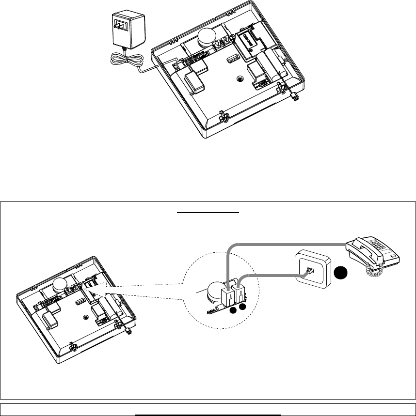
Connecting Power to Panel
Connect the power cable and close the control panel as shown below. Electrical socket-outlet shall be installed
near the equipment and shall be easily accessible.
WARNING! DO NOT USE AN OUTLET CONTROLLED BY A WALL SWITCH.
Note: This equipment should be installed in accordance with Chapter 2 of the National Fire Alarm Code, ANSI/NFPA
72, (National Fire Protection Association).
Connect the power adapter to the power connector.
Figure 3.4 - Power Cable Connection
3.4 Connecting to the Telephone Line
PHONE WIRING
Connect the telephone cable to the SET connector and connect the telephone line cable to the LINE connector
(through the desired wiring cable entry). Note: The telephone cable should be no longer than 3 meters.
AB
C
A. SET
B. LINE
C. Tel line wall jack
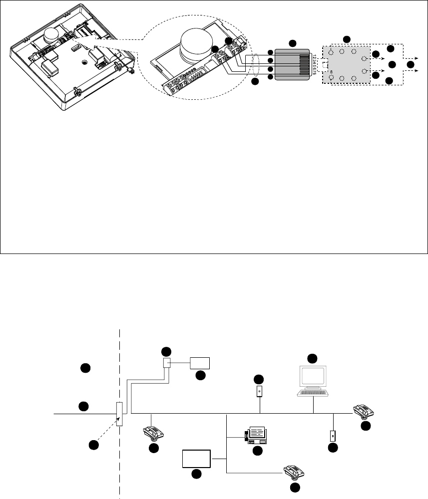
PHONE WIRING IN NORTH AMERICA
D-302756 11
RJ-31X
123
4
5
6
7
A
B
C
D
E
E
F
F
G
G
H
H
I
J K
A. SET
B. LINE
C. RJ-31X cord
D. 8-position RJ-31X plug
E. Gray
F. Red
G. Green
H. Brown
I. RJ-31X jack
J. Line from street
K. House phones
Figure 3.5 – Phone Wiring
This equipment is designed to be connected to the
telephone network using RJ11 connector which
complies with Part 68 rules and requirements adopted
by ACTA and properly installed RJ31X connector. See
drawing below for details.
In the case that RJ31X is not available (consult your
telephone company or a qualified installer), the
telephone line should be connected to the
PowerMaster-10 unit first and then all other home
equipment should be connected to PowerMaster-10
"Phone" outlet.
Customer Premises Equipment And Wiring
A
B
C
D
E
F
G
H
I
E
E
H
J
A. Network Service Provider's Facilities
B. Telephone Line
C. Network Demarcation Point
D. RJ-31X Jack
E. Telephone
F. Alarm Dialing Equipment
G. Answering System
H. Unused RJ-11 Jack
I. Fax Machine
J. Computer

12 D-302756
Note: The REN is used to determine the number of devices that may be connected to a telephone line. Excessive
RENs on a telephone line may result in the devices not ringing in response to an incoming call. In most but not all
areas, the sum of RENs should not exceed five (5.0). To be certain of the number of devices that may be
connected to a line, as determined by the total RENs, contact the local telephone company.
Connection to telephone company provided coin service is prohibited. Connection to party lines service is
subject to state tariffs.
The installer should verify line seizure. Be aware of other phone line services such as DSL. If DSL service is
present on the phone line, you must install a filter. It is suggested to use the DSL alarm filter model Z-
A431PJ31X manufactured by Excelsus Technologies, or equivalent. This filter simply plugs into the RJ-31X jack
and allows alarm reporting without breaking the internet connection.
3.5 System Planning & Programming
It pays to plan ahead - use the tables in appendices A and B at the end of this guide to register the intended
location of each detector, the holder and assignment of each transmitter.
Gather up all transmitters and detectors used in the system and mark each one in accordance with your
deployment plan.
Program the system now, before mounting, as instructed in the programming section.
3.6 Extension Modules GSM Installation
The internal GSM 350 module enables the PowerMaster-10 system to operate over a GSM/GPRS cellular
network (for further details, see the GSM 350 PG2 Installation Instructions).
The GSM modem auto detection feature enables automatic enrollment of the GSM modem into the
PowerMaster-10 control panel memory. GSM modem auto detection is activated in one of two ways: after
tamper restore and after reset (power-up or after exiting the installer menu). This causes the PowerMaster-10 to
automatically scan GSM COM ports for the presence of the GSM modem.
In the event that the GSM modem auto detection fails and the modem was previously enrolled in the
PowerMaster-10.
G2 control panel, the message "Cel Rmvd Cnfrm" will be displayed. This message will disappear from the
display only after the user presses the button. The modem is then considered as not enrolled and no
GSM trouble message will be displayed.
Note: A message is displayed only when the PowerMaster-10 alarm system is disarmed.
PowerLink Broadband Module Installation
The PowerLink broadband module enables viewing the PowerMaster-10 system over the internet (for further
details, see the PLINK PRO Installation Instructions).
The PowerLink Broadband Module modem auto detection feature enables automatic enrollment of the
PowerLink Broadband Module modem into the PowerMaster-10 control panel memory. The PowerLink
Broadband Module modem auto detection is activated in one of two ways: after tamper restore and after reset
(power-up or after exiting the installer menu). This causes the PowerMaster-10 to automatically scan the
PowerLink Broadband Module COM ports for the presence of the PowerLink Broadband Module modem.
In the event that the PowerLink Broadband Module modem auto detection fails and the modem was previously
enrolled in the PowerMaster-10 control panel, the message "PLNK Remvd Cnfrm" will be displayed. This message will
disappear from the display only after the user presses the button. The modem is then considered as not
enrolled and no PowerLink Broadband Module trouble message will be displayed.
Notes:
A message is displayed only when the PowerMaster-10 alarm system is disarmed.
In the event of a power failure the PowerLink Broadband Module will not operate. Power (AC or battery) must be
disconnected from the circuit before connecting / disconnecting the PowerLink Broadband Module.
D-302756 13
3.7 Annual System Check
Note: This system must be checked by a qualified technician at least once every three (3) years (preferably
every year).
The annual system check is designed to ensure proper operation of the alarm system by performing the
following checks:
Periodic test
Arm/disarm function
No trouble messages are displayed on control panel
The clock displays the correct time
Reporting: generating an event to be transmitted to the central station and to the user.
14 D-302756
4. PROGRAMMING
4.1 General Guidance
We recommend programming the PowerMaster-10 on the work bench before actual installation. Operating
power may be obtained from the backup battery or from the AC power supply.
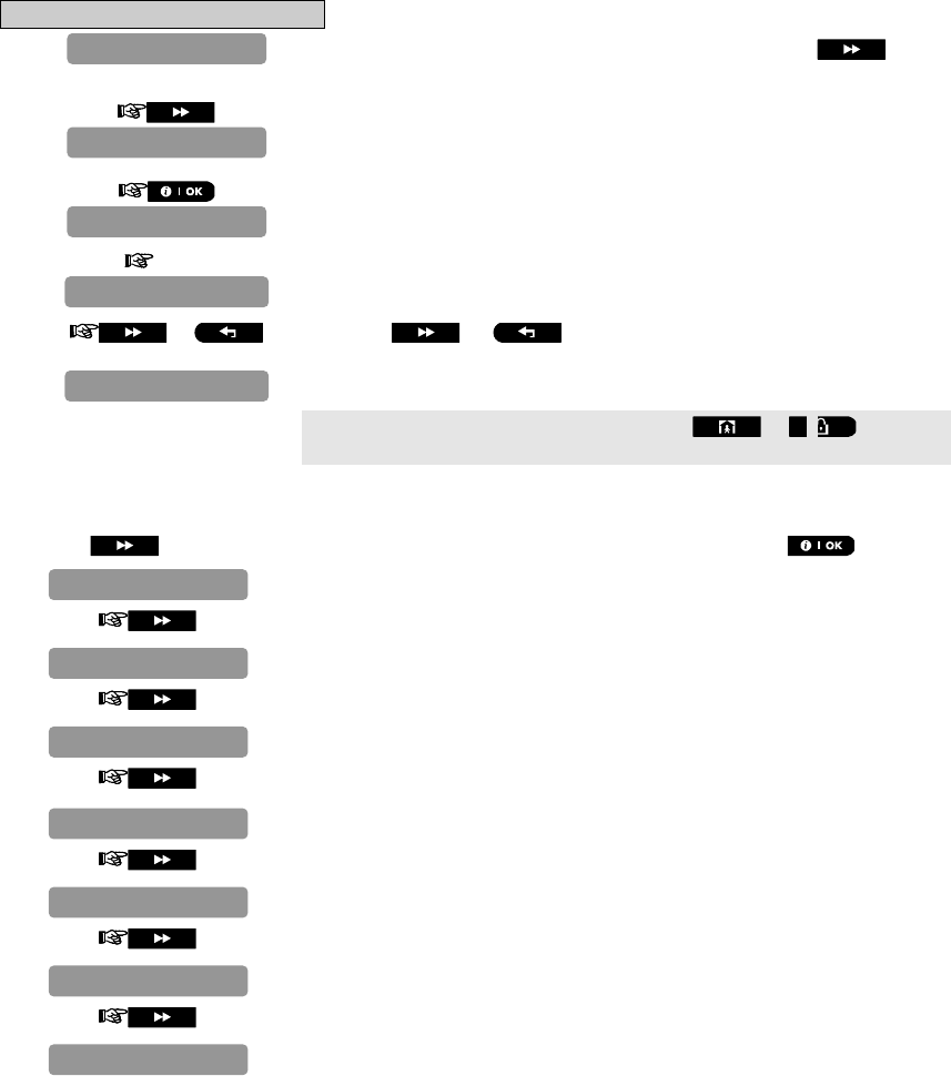
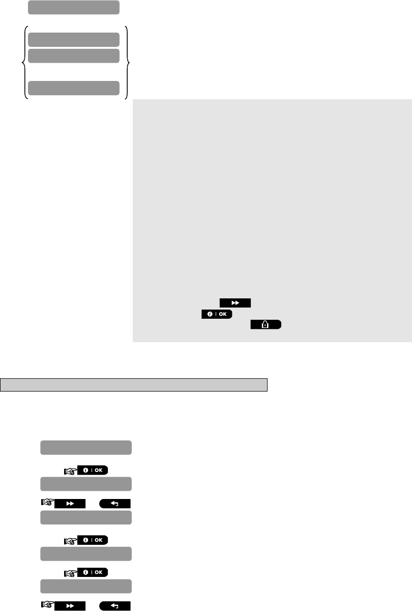
4.2 Entering the Installer Menu
The following procedure describes how to enter the Installer Menu.
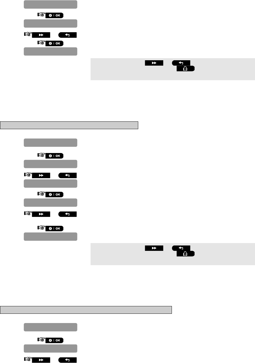
To Enter the Installer Menu
1. Make sure the system is disarmed and then press the button
repeatedly until the PowerMaster-10 display reads "INSTALLER MODE".
2.
3. CODE Enter your Installer Code.
4. or Press the or button repeatedly until the display reads the
desired setting option, for example, "ZONES/DEVICES".
You can program any other menu or press the or buttons to
take you to "<OK> TO EXIT".
Installer Mode Options Menu
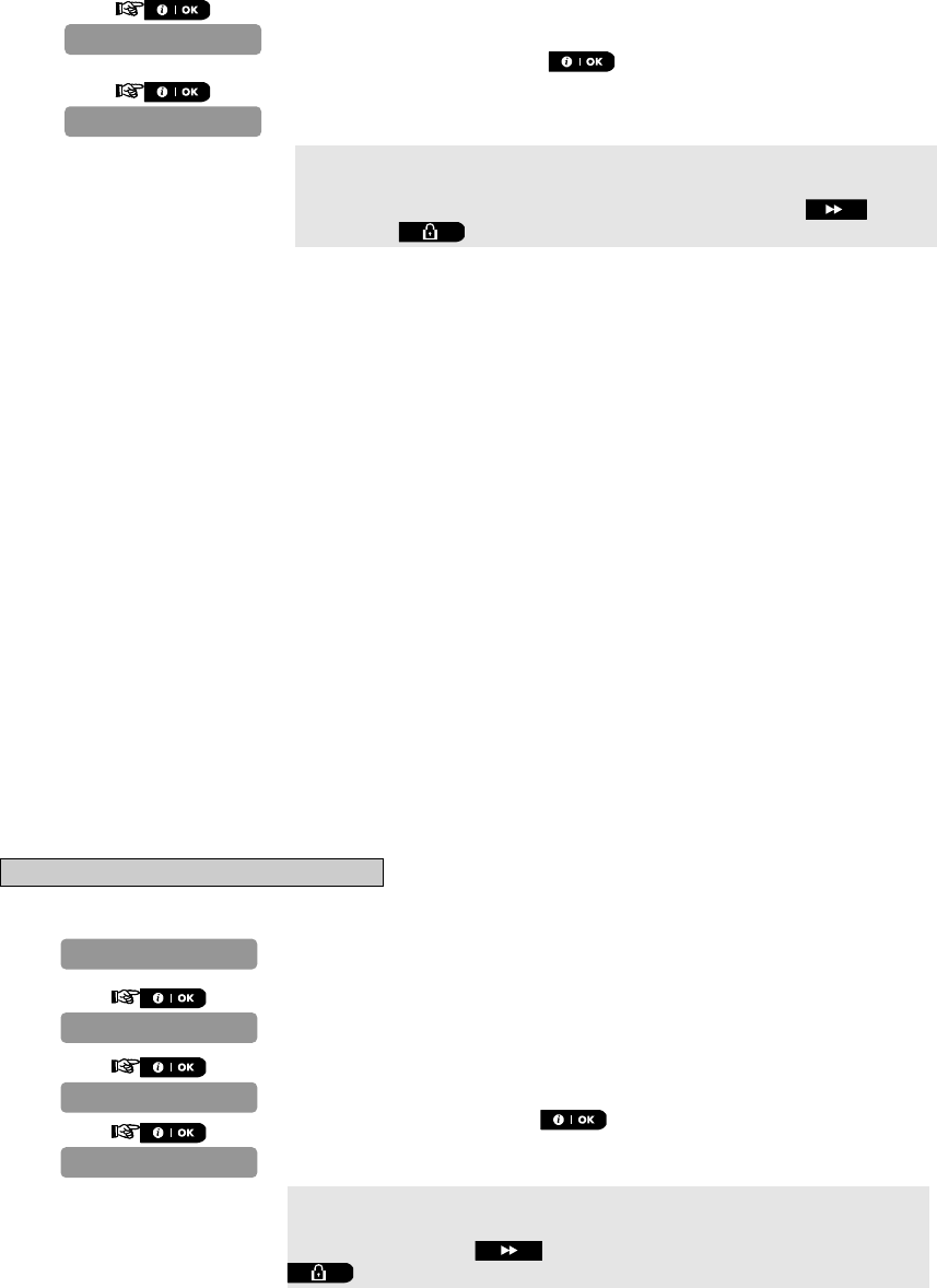
Click the button until the display reads the desired setting option and then press the button.
Use to program the Installer Code and the Master Installer Code. See
section 4.4.1
Use to Add, Delete, Configure, Replace and Configure devices and also to
define your personal set of Defaults for device configuration. See section 4.5.
Use to define control panel parameters. See sections 4.6, 4.8, 4.9 and 4.10.
Use to define control panel communication parameters. See section 4.7.
Use to define the PGM output. See section 4.12.
Use to define custom zone names. See section 4.11.
Use to test and identify devices and wireless communication link quality. See
Chapter 5
DIAGNOSTICS
DEFINE CUSTOM
DEFINE OUTPUTS
DEFINE COMM.
DEFINE PANEL
ZONES/DEVICES
NEW INSTL CODE
ZONES DEVICES
NEW INSTL CODE
ENTER CODE:
INSTALLER MODE
READY 00:00
D-302756 15
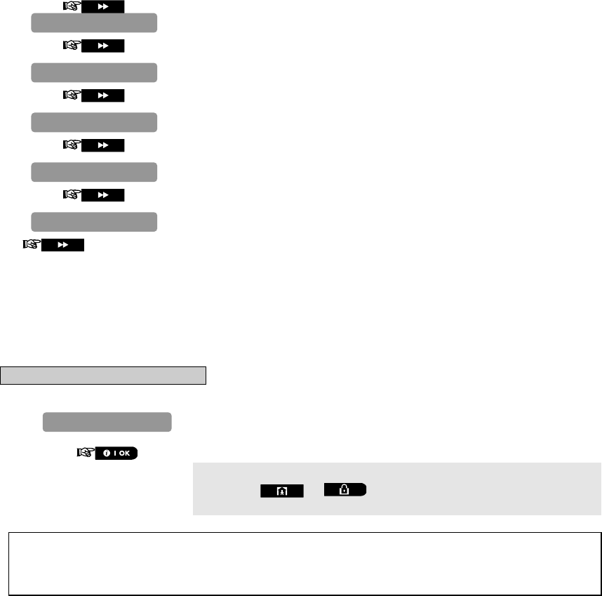
Chapter 5.
Use to enter the USER SETTINGS menu to perform user settings. See
section 4.2.
Use to restore the control panel to factory defaults. See section 7.6.
Use to read the serial number of the control panel. See section 7.7.
Use to initiate the upload/download process. See Chapter 6.
Returns to first
option
Use to exit from the “INSTALLER MODE” menu back to Main Menu. See
section 4.3.
Programming User Settings
This mode provides you with a gateway to the user functions through the regular user programming menu.
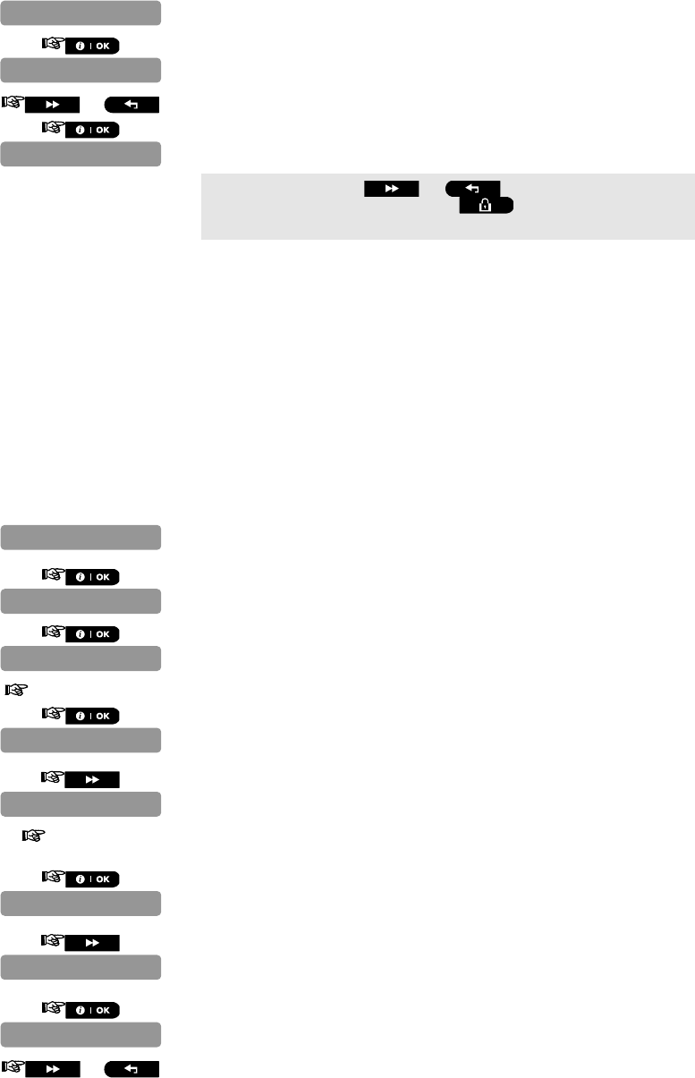
To Enter the User Settings Menu
1. Repeat steps 1 to 4 of section 4.2 "Entering the Installer Menu".
2.
Refer to the PowerMaster-10 User Guide for detailed procedures
Clicking the or buttons at any stage in the procedure will
take you to “<OK> TO EXIT”.
Caution! If after having programmed the user codes the system does not recognize your installer code,
this indicates you must have programmed a user code that is identical with your installer code. If so,
access the user menu and change the code that is identical with your installer code. This will re-validate
your installer code.
<OK> TO EXIT
START UL/DL
SERIAL NUMBER
FACTORY DEFLT
USER SETTINGS
USER SETTINGS
16 D-302756
4.3 Navigation
This mode allows you to customize the control panel and adapt its characteristics and behavior to the requirements
of the particular user. To review the options within the control panel menus, repeatedly press the or
button, until the desired option is displayed, then press the button.
You will mainly use 5 control pushbuttons during the entire programming process:
- to move one step forward in a menu.
- to move one step backward in a menu.
- to enter the relevant menu or confirm data.
- to move one level up in a menu.
- to return to the "OK TO EXIT" state.
The sounds you will hear while programming are:
- Single beep, heard whenever a key is pressed.
- Double beep, indicates automatic return to the normal operating mode (by timeout).
- Happy Melody (- - - –––), indicates successful completion of an operation.
- Sad Melody (–––––), indicates a wrong move or rejection.
If you enter an invalid installer code 5 times, the keypad will be automatically disabled for 90 seconds and the
message WRONG PASSWORD will be displayed.
4.4 Permissions and User Codes
The PowerMaster-10 system includes four code levels, as follows:
Installer Code: By using the installer code, the menu enables changing the installer code.
Master Installer Code: By using the master installer code, the menu enables changing both master installer
code and installer code.
User Code: See PowerMaster-10 User Guide
Master User Code: See PowerMaster-10 User Guide
Not every system includes a MASTER INSTALLER code. In a system with an INSTALLER code only, the installer
can use all the functions in the system.
The following actions can be done only by using the master installer code:
Changing master installer code.
Resetting the PowerMaster-10 parameters to the default parameters,
Defining specific communication parameters.
You are expected to use this code only once for gaining initial access, and replace it with a secret code known
only to yourself.
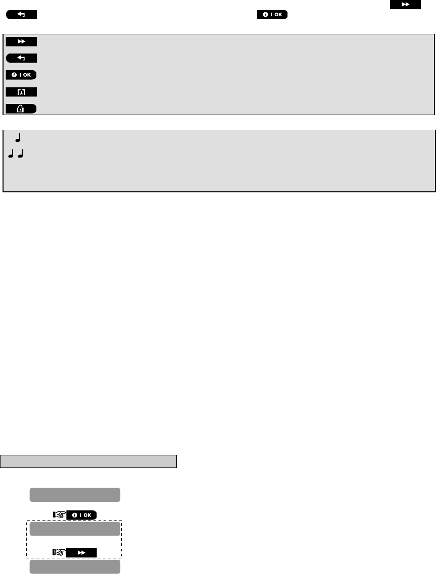
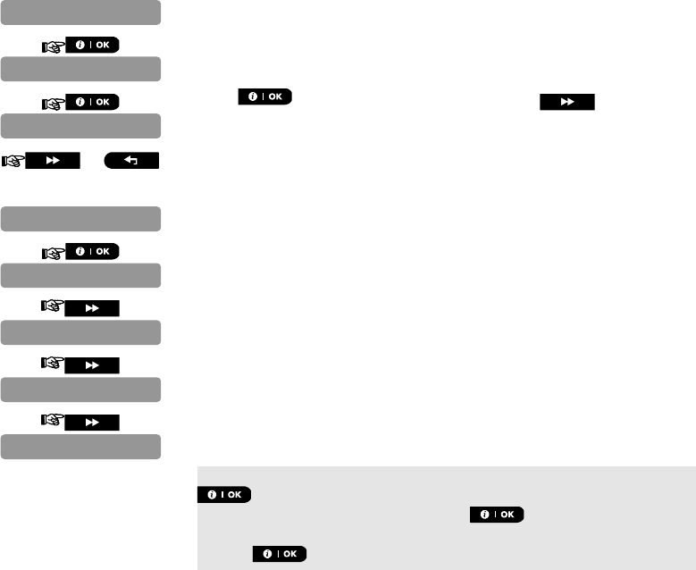
4.4.1 Setting a New Installer Code
To set an installer code, perform the actions that are presented below. When you are instructed to enter code,
enter a 4-digit code.
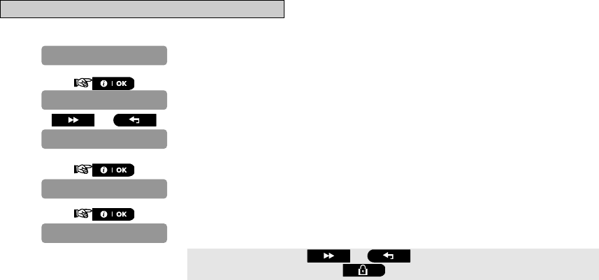
A. To Set a New Installer Code
1. Repeat steps 1 to 4 of section 4.2 "Entering the Installer Menu".
2.
Note: The menu displayed within the dashed box appears only if the control panel
includes the Master Installer Code.
3.
4.
NEW INST. CODE
NEW MASTER CODE
NEW INSTL CODE
D-302756 17
5. Enter the new 4-digit Installer Code (8888 or 9999) at the position of the
blinking cursor and then press .*
* The default Installer Code is 9999.
If your system uses MASTER CODE, you should proceed to setting the
MASTER INSTALLER code in section 4.4.2 by pressing the button,
or press the button to take you to "<OK> TO EXIT".
Note: Installer Code should never be programmed as “0000”. Doing so will lock the user out of the installer
menu!
4.4.2 Setting the Master Installer Code
For PowerMaster-10 with MASTER INSTALLER code, set a new INSTALLER code as described in section
4.3.1 "Setting a New Installer Code" and set the MASTER INSTALLER code as described in this section.
Note: For Control Panel that has installer code & master installer code, the following functions are available only
if the MASTER INSTALLER code is entered:
PSTN/GSM RCVR1
RCVR 1 ACCOUNT#
PSTN/GSM RCVR2
RCVR 2 ACCOUNT#
PSTN RPRT FORMAT
4/2 PLS RATE
REPORT EVENTS
RPRT CNFRM ALRM
SEND 2WV CODE
RINGBACK TIME
PSTN RPRT RETRY
GSM RPRT RETRY
MAST. DL CODE
By using the master installer code, the menu enables changing both master installer code and installer code.
By using the installer code, the menu enables changing the installer code only.
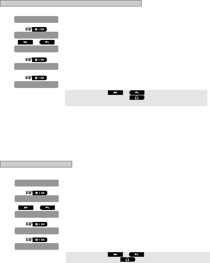
B. To Set a New Master Installer Code
1. Repeat steps 1 to 4 of section 4.2 "Entering the Installer Menu".
2.
3.
Enter the new 4-digit Installer Code (8888 or 9999) at the position of the
blinking cursor and then press .*
* Master Installer Code should never be programmed as “0000”. Doing so
will lock the user out of the installer menu!
You can now press the button to set the INSTALLER code or press the
button to take you to "<OK> TO EXIT".
NEW MASTER CODE
MASTER CODE 999
NEW MASTER CODE
NEW INSTL CODE
NEW INST. CODE
INST. CODE 888
18 D-302756
4.4.3 Setting User Codes
For detailed instructions on setting user codes, refer to the PowerMaster-10 user guide "Menus and Functions".
4.4.4 Enabling User Permit for Installer Access
User Permission enables you to determine whether access to the INSTALLER MODE requires user permission.
Access to the installer menu, in PowerMaster-10 that has "User Permission" enabled (for example, in UK) is via the
last menu in the user menu. This option can be changed, if necessary. Here you determine whether the access to
the INSTALLER MODE requires user permission. If you select ENABLE, the installer mode will be accessible only
through the user menu after entering the user code.
Options: Enable (default in UK), Disable (default).
Note: To comply with EN requirements, "Enable" must be selected.
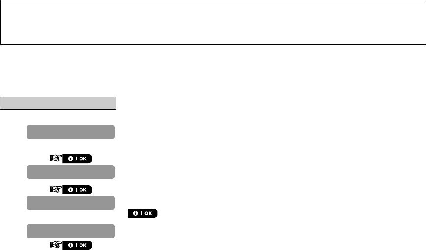
To Enable User Permit for Installer Access
1. Repeat steps 1 to 4 of section 4.2 "Entering the Installer Menu".
2.
3.
4. or
5.
Select between "Disable" (default) and "Enable".
You can now press the or button to program any other menu in
"DEFINE PANEL" or press the button to take you to "<OK> TO EXIT".
4.4.5 Configuring Permissions for System Reset after Alarm Event
(Not applicable in the USA)
Here you determine whether the system can be rearmed (after an event) by the user or only by the installer.
Options: user reset (default), engineer reset, or anti code reset.
If Engineer Reset is selected, the system can be rearmed only by the installer; by entering and exiting the installer
menu, by entering and exiting the event log (see section 8), or by remote telephone. To perform Engineer Reset via
the telephone, establish communication with the PowerMaster-10 (see user guide, Chapter 5) and continue as
follows:
a. "*", "installer code", "#"
b. Wait for 2 beeps
c. "*", "1", "#"
d. "*", "99", "#"
Visonic uses Technistore anti code reset. Installers should check with their Monitoring Station for a code version
(seed code) which needs to be entered.
36:USER PERMIT
01:ENTRY DELAY 1
36:USER PERMIT
Disable
DEFINE PANEL
D-302756 19
To Configure Permissions for System Reset after an Alarm Event
1. Repeat steps 1 to 4 of section 4.2 "Entering the Installer Menu".
2.
3.
4. or
5.
Select between "user reset" (default), "engineer reset" and "anti
code reset".
You can now press the or button to program any other menu
in "DEFINE PANEL" or press the button to take you to "<OK> TO
EXIT".
4.4.6 Configuring a Duress Code
A duress alarm (ambush) message can be sent to the Monitoring Station if the user is forced to disarm the system
under violence or menace. To initiate a duress message, the user must disarm the system with the duress code
(2580 by default). Here you can change the code digits or enter "0000" to disable the duress feature. The system
does not allow the user to program the duress code saved in this memory location as an existing user
code.
Note: Duress Code is not applicable in the UK.
To Configure a Duress Code
1. Repeat steps 1 to 4 of section 4.2 "Entering the Installer Menu".
2.
3.
4. or
5.
Change the code or enter 0000 to disable the duress function.
You can now press the or button to program any other menu in
"DEFINE PANEL" or press the button to take you to "<OK> TO EXIT".
01:ENTRY DELAY 1
25:RESET OPTION
23:DURESS
DURESS CODE 2580
23:DURESS
01:ENTRY DELAY 1
DEFINE PANEL
25:RESET OPTION
user reset
DEFINE PANEL
20 D-302756
4.5 Zones / Devices
4.5.1 General Guidance
The ZONES / DEVICES mode enables the following functions:
- Defining default parameters common for each devices family.
- Adding new devices (enrolling) and defining their zones name, zone type and chime zone.
- Deleting devices.
- Modifying devices parameters.
- Reviewing devices parameters.
Enrolling can be performed for Keyfobs (multi-button), wireless detectors, wireless sirens and repeaters.
The control panel enables entering a device identification (ID) instead of enrolling an actual device. This enables pre-
enrolling off site.
Upon boot up, the control panel checks if there are pre-enrolled devices that have not yet been registered (ID of the
devices are entered but the devices have not communicated with the control panel). In this case, the control panel will
display "SYNC WITH DEV" on the LCD and the trouble LED will be on until all the devices have registered or the pre-
enrolled devices that have not registered will be deleted from the enrollment menu.
Refer to sections 4.4.3 and 4.4.4 for detailed instructions on Enrolling/Deleting a device.
Notes
- Keyfob enrolling can be performed also by the user (via USER SETTINGS menu).
- Wired magnetic contact or any other contact can be enrolled in zones 29 & 30.
- Wireless detectors can be enrolled in zones 01-28.
Before beginning, gather all the devices that you intend to enroll and make sure they all have batteries installed.
Your control panel must recognize the unique identification code (ID) of each such detector in order to supervise
them, receive their signals and respond accordingly.
Before enrolling, the lens at the front of PIR and dual-technology sensors should be masked to prevent inadvertent
transmission.
Make sure that magnetic contact transmitters are together with their magnets, to prevent them from sending
out alarm transmissions.
4.5.2 Adding a Wireless Device
This section describes how to add a new device to the PowerMaster-10 control panel.
Note: It is much easier to enroll the device while holding the device in your hand, close to the control panel.
A. To Add a Device
1. Repeat steps 1 to 4 of section 4.2 "Entering the Installer Menu".
2.
3.
4. You are now instructed to enroll the device.
5.
Enter the 7-digit number printed on the back side of the device and press
.*
or
Perform the enrollment sequence for the specific device:
For most devices: Remove the device bracket or cover and press the
device's Enroll button continuously until the red & green LEDs turn ON
and then release. The PowerMaster-10 will indicate the result on its LCD
display.
For Keyfobs: Press the '*' button until the red LED blinks rapidly and then
release (the LED will continue blinking) then press the same button again.
The LED lights green and the PowerMaster-10 will indicate the result on its
LCD display.
ZONES/DEVICES
ENTR ID: XXX-
ENROLL NOW or
ADD NEW DEVICES
D-302756 21
………..
The PowerMaster-10 display reads "DEVICE ENROLLED" (or "ID
accepted" if the device was enrolled manually by entering the ID number)
and the PowerMaster-10 display will then change to "K01:Keyfob /
Z01:Motion Sens / S01:Siren depending on the type of enrolled
device".
However, if the device was previously enrolled in the system, the
PowerMaster-10 display reads "ALREADY ENROLLED".
Repeat the above procedure for each device to be enrolled in the
PowerMaster-10 system.
Continue to section 4.4.2.1 Assigning a Location, Zone Type and Chime
Option.
When exiting "ZONES / DEVICES" menu the PowerMaster-10 system
displays the number of devices that need to be updated, as follows: DEV
UPDATING NNN.
* If you enter the 7-digit number, you must physically install the device
to complete the procedure. If the device is not installed, the system will
display the device as "NOT NET" (device is pre-enrolled – not
networked).
You can now press the button to enroll the next device of the same
type or press the button to move to the "LOCATION" menu (see
section 4.4.2.1) or press the button to take you to "<OK> TO
EXIT".
4.5.2.1 Assigning a Location, Zone type and Chime Option
B. To Assign a Location, Zone Type and Chime Option
The PowerMaster-10 system behavior is defined according to one of 11 zone types assigned to each of the
system's 30 (wireless & wired) zones.
Note: This step is applicable to detectors only.
Continue below from the previous section.
1.
2. or
3.
4.
5. or Select a zone type, or, enter the zone type number, for example, pressing
03 selects "3. Home Delay".
12.Non-Alarm
Master Bdrm
Z01:ZONE TYPE
Front door
Z01:LOCATION
S01:Siren
Z01:Motion Sens
K01:Keyfob
DEVICE ENROLLED
22 D-302756
To understand the behavior of each zone, see section 4.5.2.3 Zone
Types.
6.
7. Press to change chime settings or press the button to skip.
8. or Select between "Chime off" and "melody-chime".
Note: In "melody chime" mode when a chime zone is triggered, chime
melody is heard.
9.
10.
*
11.
*
12.
*
* When the PowerMaster-10 will read "NEXT device" you can click the
button to enroll the next device. When the PowerMaster-10 will read
"MODIFY SAME Dev." you can click the button to modify the same
device. When the PowerMaster-10 will read "EXIT Enrollment" you can
click the button to revert to "ADD NEW DEVICES".
4.5.2.2 Configuring Device Parameters
Refer to the PowerMaster-10 Accessories Guide for detailed instructions on how to modify specific device
settings for each device
4.5.2.3 Zone Types
Upon enrollment of a new detector (marked "Zxx") you must select the proper zone type. The zone type determines
how the system handles alarms and other signals sent from the device.
A list of factory defaults is printed in Appendix D. You may fill out the blank columns even before you start and
proceed to program according to your own list.
Zone types are fully explained below:
Delay Zones:
A delay zone has exit and entry delays set by you in the course of programming the system. Warning beeps will
sound throughout these delays, unless you choose to mute them.
Exit Delay - The exit delay begins once the user arms the system. It allows him to leave via interior zones and a
doorway before arming actually takes effect. When the exit delay starts, the buzzer beeps slowly and maintains a
slow beeping rate until the last 10 seconds, during which it beeps rapidly. The PowerMaster-10 has two types of
delay zones, for which different delay times may be set.
Entry Delay - The entry delay begins once the user enters the protected area via a specific doorway (his
entry is sensed by a delay zone detector). To avoid an alarm, he must reach the keypad via interior zones
(which become "follower zones" during the entry delay) and disarm the system before the delay expires.
When the entry delay starts, the buzzer beeps slowly until the last 10 seconds, during which it beeps rapidly.
Remember!
A delay zone is also a perimeter zone by definition.
EXIT Enrollment
MODIFY SAME Dev.
NEXT device
Z01:DEV SETTINGS
melody-chime
Chime off….
Z01:SET CHIME
3.Home Delay

D-302756 23
Emergency Zones:
You can provide incapacitated, sick or elderly people with a miniature single-button transmitter to be carried on
the neck like a pendant or to be worn on the wrist like a watch. In distress situations, they can press the button
on their transmitter, causing the PowerMaster-10 to send an emergency call to the Monitoring Station or to
private telephones designated by the installer.
To make this possible, define the required number of zones as emergency zones and enroll a portable
transmitter to each one of these zones. When completed, ask the master user to distribute these transmitters to
their potential users.
Interior Zone:
Interior zones are zones within the protected premises that have nothing to do with perimeter protection. Their
most important feature is that they allow free movement within the protected area without initiating an alarm,
provided that the system is armed in the "HOME" mode. People can therefore stay at home and move about
freely, as long as they do not disturb a PERIMETER zone.
Once the system is armed in the AWAY mode (all zones are protected), interior zones will initiate an alarm if violated.
Interior Follower Zones:
"Interior Follower" zone is a zone that is located between entry/exit zone and the alarm system control panel.
This zone is temporarily ignored by the alarm system during entry/exit delay periods, to enable you to walk
(without causing an alarm) in front of a motion detector that is associated with the Interior Follower zone, after
you enter through an entry zone on the way to the control panel, or when leaving the protected premises after
system arming.
Home/Delay Zones:
A zone type which functions as a delay zone when the system is armed HOME and as a perimeter-follower zone
when the system is armed AWAY.
Non-Alarm Zones:
A non-alarm zone does not directly participate in the alarm system. It can be used for chime or for optional KEY
ON-OFF feature (when enabled).
You can define the desired number of non-alarm zones and enroll a portable transmitter or a wireless device
(detector) to this type of zone.
Perimeter Zones:
Perimeter zones rely on detectors designed to protect doors, windows and walls. An immediate alarm is initiated
when such a zone is violated by opening the door/window or by trying to break the wall.
Perimeter Follower Zones:
A non-entry/exit zone, typically a perimeter zone located on an entry/exit path, that is treated as an entry/exit
zone during an entry/exit time.
24-Hour Zones:
24 hour zones are mainly used for PANIC buttons, perimeter detectors and anti-tamper protection. They therefore
trigger an alarm in both armed and disarmed states.
24 Hour Zone - Silent. - Upon detection, this zone initiates a silent alarm, meaning that the sirens do not
function. Instead the PowerMaster-10 dials telephone numbers and reports the event to Monitoring Stations
and/or to private telephones, as programmed.
24 Hour Zone - Audible. - Upon detection, this zone initiates a siren alarm. The PowerMaster-10 also dials
telephone numbers and reports the event to Monitoring Stations and/or to private telephones, as
programmed.
4.5.2.4 Locations
You can select or assign a named location to a device (e.g. Garage, Front Door etc.). 31 locations can be
selected, 26 fixed names and 5 custom names (defined by the installer).
Note: Custom Locations can be defined via the DEFINE CUSTOM menu, and these custom names will also
appear on your location list in addition to the default names.
Note: To facilitate assigning a location name to a device, a shortcut procedure may be used by entering the
location number which takes you directly to the location name.
Selectable Locations:
Attic
Back door
Basement
Bathroom
Bedroom
24 D-302756
Child room
Closet (UK: Conservatory)
Den (UK: Playroom)
Dining room
Downstairs
Emergency
Fire
Front door
Garage
Garage door
Guest room
Hall
Kitchen
Laundry room
Living room
Master bath
Master bdrm
Office (UK: Study)
Upstairs
Utility room
Yard (UK: Garden)
Custom 1
Custom 2
Custom 3
Custom 4
Custom 5
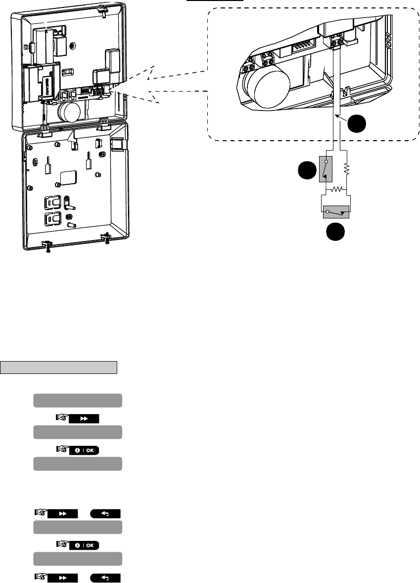
4.5.3 Adding Wired Zones
Required tools: Cutter and slotted screwdriver - 3 mm blade.
PowerMaster-10 wiring is shown in Figure 4.1.
CABLES ROUTING GUIDE
1 2
A
B
C
A. Cables entry options
B. Back unit
C. Cable clips
To Route the Cable:
1. Remove the left or right side cables entry knockout(s) and enter the required cable(s)
2. Remove and use as cable clamp(s)
D-302756 25
ZONE WIRING
2.2k
2.2k
A
B
C
A. ZONE
B. TAMPER
C. ALARM
Note: Do not use mains cable other than that supplied by the manufacturer (3 m long).
Figure 4.1 - Wiring
4.5.4 Deleting a Device
C. To Delete a Device
1. Repeat steps 1 to 3 in section 4.5.2 "Adding a Wireless Device".
2.
3.
4.
or
Select the type of device to be deleted. Select between "CONTACT
SENSORS", "MOTION SENSORS", "SMOKE SENSORS", "WIRED SENSORS",
"KEYFOBS", "SIRENS" and "REPEATERS" for example, "MOTION
SENSORS".
5.
6. or Select the motion sensor to be deleted, for example, "Z03:Motion
Sens".
Z01:Motion Sens
MOTION SENSORS
CONTACT SENSORS
DELETE DEVICES
ADD NEW DEVICES
26 D-302756
7.
8.
The device is deleted from the PowerMaster-10 system.
When exiting "ZONES / DEVICES" menu the PowerMaster-10 system
displays the number of devices that need to be updated, as follows: DEV
UPDATING NNN.
You can now press the button to delete the device of the same
type, or press the button to delete a different device, or press the
button to take you to "<OK> TO EXIT".
4.5.5 Modifying a Device
D. To Modify a Device
Note: This procedure is applicable to detectors only.
1. Repeat steps 1 to 3 in section 4.5.2 "Adding a Wireless Device".
2. or
3.
Select the desired sensor to be modified. Select between "CONTACT
SENSORS", "MOTION SENSORS", "SMOKE SENSORS" and "WIRED
SENSORS", for example, "MOTION SENSORS".
4. or
5.
6.
The PowerMaster-10 display will read "Front door".
7. or Select a location, or, enter the location number, for example,
"Master Bdrm".
8.
9.
10
or
Select a zone type, or, enter the zone type number, for example,
pressing 03 selects "3. Home Delay".
To understand the behavior of each zone, see section 4.5.2.3 Zone
Types.
12.Non-Alarm
Z01:ZONE TYPE
Master Bdrm
Front door
Z01:LOCATION
Z01:Motions Sens
CONTACT SENSORS
MODIFY DEVICES
ADD NEW DEVICES
MOTION SENSORS
(OFF) to delete
Z03:Motion Sens
D-302756 27
11.
12. Press to change chime settings or press the button to
skip.
13. or Select between "CHIME OFF" and "melody-chime".
Note: In "melody chime" mode when a chime zone is triggered, chime
melody is heard
14.
You can now press the button to modify the next device of the
same type, or press the button to configure the parameters of the
device (see the Accessories Guide for instructions), or press the
button to take you to "<OK> TO EXIT".
4.5.6 Replacing a Device
This feature is used for replacing a device that is enrolled in the system with another device of the same type
while keeping the same parameters of the original device. This can save valuable time, since instead of having
to delete the original device from the control panel, then to enroll the new device and then to set the device
parameters again – all this can now be performed in one short procedure.
To Replace a Device
1. Repeat steps 1 to 4 of section 4.2 "Entering the Installer Menu".
2.
3. or
4.
5. or Select the desired device type to be replaced. Select between "CONTACT
SENSORS", "MOTION SENSORS", "SMOKE SENSORS", "KEYFOBS",
"SIRENS" or "REPEATERS", for example, "CONTACT SENSORS".
6.
The PowerMaster-10 display will read the name of the first enrolled
device of the selected type to be replaced alternating with the ID number
of the device.
7 or At this stage you can select another device of the same type (in this
example, contact sensor) to be replaced.
ID No. 100-2340
Z01: Contact
CONTACT SENSORS
CONTACT SENSORS
REPLACE DEVICES
ADD NEW DEVICES
ZONES/DEVICES
Chime off….
melody-chime
Z01: SET CHIME
3. Home Delay
28 D-302756
8.
9. Enroll the new device, or, enter the last 4 digits of the ID number of the
new device.*
The PowerMaster-10 display will read the result.**
* If the device was previously enrolled in the system, the PowerMaster-
10 display reads "ALREADY ENROLLED" and then switches to the
name of the device alternating with the ID number of the device.
If the device ID number is invalid the PowerMaster-10 display reads
"WRONG ID No".
If the new device type is different from the existing device to be
replaced, the PowerMaster-10 display reads "WRONG DEV.TYPE".
** If the device was enrolled manually, by entering the ID number, the
PowerMaster-10 display reads "ID ACCEPTED".
At the end of the procedure you can press the button and perform
the same procedure for a different device of the same type, or you can
press the button to select a different device type to be replaced,
or you can press the button to take you to “<OK> TO EXIT”.
4.5.7 Defining Defaults
Attention! When changing the default parameters of one device in Define Defaults, all new devices of the same
device type that are enrolled in the PowerMaster-10 system will have the same defaults. Devices that were
already enrolled in the PowerMaster-10 system before the procedure was performed will not be affected by the
new default settings.
To Define Device Defaults
1. Repeat steps 1 to 4 of section 4.2 "Entering the Installer Menu".
2.
3. or
4.
Select the desired device whose defaults you wish to define. Select
between "CONTACT SENSORS", "MOTION SENSORS", "SMOKE SENSORS",
"KEYFOBS" and "SIRENS", for example, "KEYFOBS".
5. or
ID No. 100-2332
DEVICE ENROLLED
Z01: Contact
ENTR ID:100-xxxx
ENROLL NOW or
KEYFOBS
CONTACT SENSORS
DEFINE DEFAULTS
ADD NEW DEVICES
ZONES/DEVICES
D-302756 29
6.
For reviewing parameter configurations refer to the PowerMaster-10
Accessories Guide in section "MODIFY DEVICE SETTINGS" of the
desired device.
At the end of the procedure you can press the button and
perform the same procedure for a different device or you can press the
button to take you to “<OK> TO EXIT”.
4.6 Siren Configuration
4.6.1 Configuring the Length of Time the Bell is allowed to Function
Here you select the length of time the bell (or siren) is allowed to function upon alarm. The bell time starts upon
activation of the siren. Once the bell time expires, the siren is automatically shut down.
Available options are: 1, 3, 4 (default), 8, 10, 15 and 20 minutes.
Note: To comply with EN requirements, the Bell Time should be set to 15 min. max.
To Configure the Length of Time the Bell is Allowed to Function
1. Repeat steps 1 to 4 of section 4.2 "Entering the Installer Menu".
2.
3. or
4.
5. or Select between "bell time 1m", "bell time 3m", "bell time 4m",
"bell time 8m", "bell time 10m", "bell time 15m" and "bell
time 20m".
6.
You can now press the or button to program any other
menu in "DEFINE PANEL" or press the button to take you to "<OK>
TO EXIT".
4.6.2 Enabling the Internal Siren
Here you determine whether the internal siren will sound or remain silent upon alarm (according to the user
preference). Options: piezo siren on (default), piezo siren off.
To Enable the Internal Siren
1. Repeat steps 1 to 4 of section 4.2 "Entering the Installer Menu".
2.
3. or
01:ENTRY DELAY 1
DEFINE PANEL
4:BELL TIME
bell time 4m
4:BELL TIME
01:ENTRY DELAY 1
DEFINE PANEL
30 D-302756
4.
5. or Select between "piezo siren ON" and "piezo siren OFF".
6.
You can now press the or button to program any other
menu in "DEFINE PANEL" or press the button to take you to "<OK>
TO EXIT".
4.6.3 Configuring the Period of Strobe Light Activation
Here you can define the period of strobe light activation when the siren is in alarm state.
Options: 5 minutes, 10 minutes, 20 minutes (default), 40 minutes and 60 minutes.
To Configure the Period of Strobe Light Activation
1. Repeat steps 1 to 4 of section 4.2 "Entering the Installer Menu".
2.
3. or
4.
5. or Select between "5 minutes", "10 minutes", "20 minutes", "
4
0
minutes" and "60 minutes".
6.
You can now press the or button to program any other
menu in "DEFINE PANEL" or press the button to take you to "<OK>
TO EXIT".
4.6.4 Enabling Siren Activation upon Telephone Line Failure
Here you determine whether the siren will be activated or not when the telephone line fails during system armed
state. Available options are: enable on fail, disable on fail (default).
To Enable Siren Activation upon Telephone Line Failure
1. Repeat steps 1 to 4 of section 4.2 "Entering the Installer Menu".
2.
3. or
01:ENTRY DELAY 1
DEFINE PANEL
40:STROBE TIME
20 minutes
40:STROBE TIME
01:ENTRY DELAY 1
DEFINE PANEL
24:PIEZO SIREN
piezo siren ON
24:PIEZO SIREN
D-302756 31
4.
5. or Select between "disable on fail" and "enable on fail".
6.
You can now press the or button to program any other
menu in "DEFINE PANEL" or press the button to take you to "<OK>
TO EXIT".
4.7 Event Reporting Configuration
4.7.1 General
The PowerMaster-10 system uses an IP platform that supports GSM and GPRS cellular communication and
broadband to forward all events received at the control panel to the monitoring station.
4.7.2 Setup Report Communicators
4.7.2.1 Configuring PSTN / GSM Communicators
1. Repeat steps 1 to 4 of section 4.2 "Entering the Installer Menu".
2.
3.
4. TEL. AREA CODE Enter the system tel. area code (up to 4 digits).
5.
6.
7. LINE PREFIX Enter the number that is used as a prefix to access an outside telephone
line (if exists).
8.
9.
Here you determine the dialing method used by the automatic dialer built
into the PowerMaster-10 control panel.
10.
11. or Select between "Pulse" and "tone (dtmf)".
27:SIREN ON LINE
disable on fail
27:SIREN ON LINE
Pulse
DIAL METHOD
LINE PREFIX
LINE PREFIX
AREA CODE
AREA CODE
1:PSTN/GSM
DEFINE COMM.

32 D-302756
12.
13.
Here you prevent the GSM Service provider from disconnecting the GSM
line if the user has not initiated any outgoing telephone calls during the
last 28 days.
14.
15. or Select between "disable" and "every 28 days".
16.
You can now press the button to revert to the "AREA CODE" menu,
or press the button to take you to "<OK> TO EXIT".
4.7.2.2 Configuring GPRS / BB Communicators
The GSM/GPRS module is capable of communicating with the Monitoring station receiver by GPRS, GSM Voice
and SMS Channels. Each of the channels can be separately enabled or disabled in order to allow or prohibit the
module from using it for the event reporting. If all channels are enabled, the GSM/GPRS module will always try
GPRS first. If fails, it will try GSM voice. If fails, it will try any other possible method (PSTN Broadband) and only
then it will try SMS. This is due to the fact that SMS the most unreliable option of communication. Disabling any
of the GSM Module channels will cause the module to use a different sequence than the one described above.
1. Repeat steps 1 to 4 of section 4.2 "Entering the Installer Menu".
2.
3.
4.
Here you determine whether the alarm system will report events to the
Monitoring Station via the GPRS Channel.
5.
6. or Select between "disable" and "enable".
7.
8.
Here you determine whether the alarm system will report events to the
Monitoring Station via the GSM Voice channel.
9.
10. or Select between "disable" and "enable".
11.
GPRS REPORT
disable
disable
GSM REPORT
GPRS REPORT
2:GSM/GPRS
1:PSTN/GSM
DEFINE COMM.
GSM KEEP ALIVE
disable
GSM KEEP ALIVE
DIAL METHOD

D-302756 33
12.
Here you determine whether the alarm system will report events to the
Monitoring Station via the SMS Channel.
13.
14. or Select between "disable" and "enable".
15.
16.
17.
18. APN NAME Enter the name of the APN Access Point used for the internet settings for
the GPRS (up to 40 digits).
Note: The table at the end of this section provides a list of the keys used
by the PowerMaster-10 editor.
19.
20.
21.
22. APN USERNAME Enter the username of the APN used for GPRS communications (up to
30 digits).
Note: The table at the end of this section provides a list of the keys used
by the PowerMaster-10 editor.
23.
24.
25.
26. APN PASSWORD Enter the password of the APN used for GPRS communications (up to 16
digits).
Note: The table at the end of this section provides a list of the keys used
by the PowerMaster-10 editor.
27.
28.
29.
30. PIN CODE Enter the PIN code of the SIM card installed in the PowerMaster-10 unit
(up to 16 digits).
31.
GPRS PASSWORD
GPRS USERNAME
GPRS USERNAME
GPRS APN
GPRS PASSWORD
PIN CODE
GPRS APN
SMS REPORT
GSM REPORT
disable
SMS REPORT
34 D-302756
32.
Here you determine whether to force the SIM card to use the home
network only and not to select another network in case the home
network cannot be found.
33.
34. or Select between "disable" and "enable".
35.
36.
Here you determine whether the control panel will stay continuously
connected via GPRS communication, or, temporarily connected to receive
event reports only.
37.
38. or Select between "off on timeout" and "always ON".
39.
You can now press the button to take you to the "
G
PRS
REPORT" menu, or press the button to take you to "<OK> TO
EXIT".
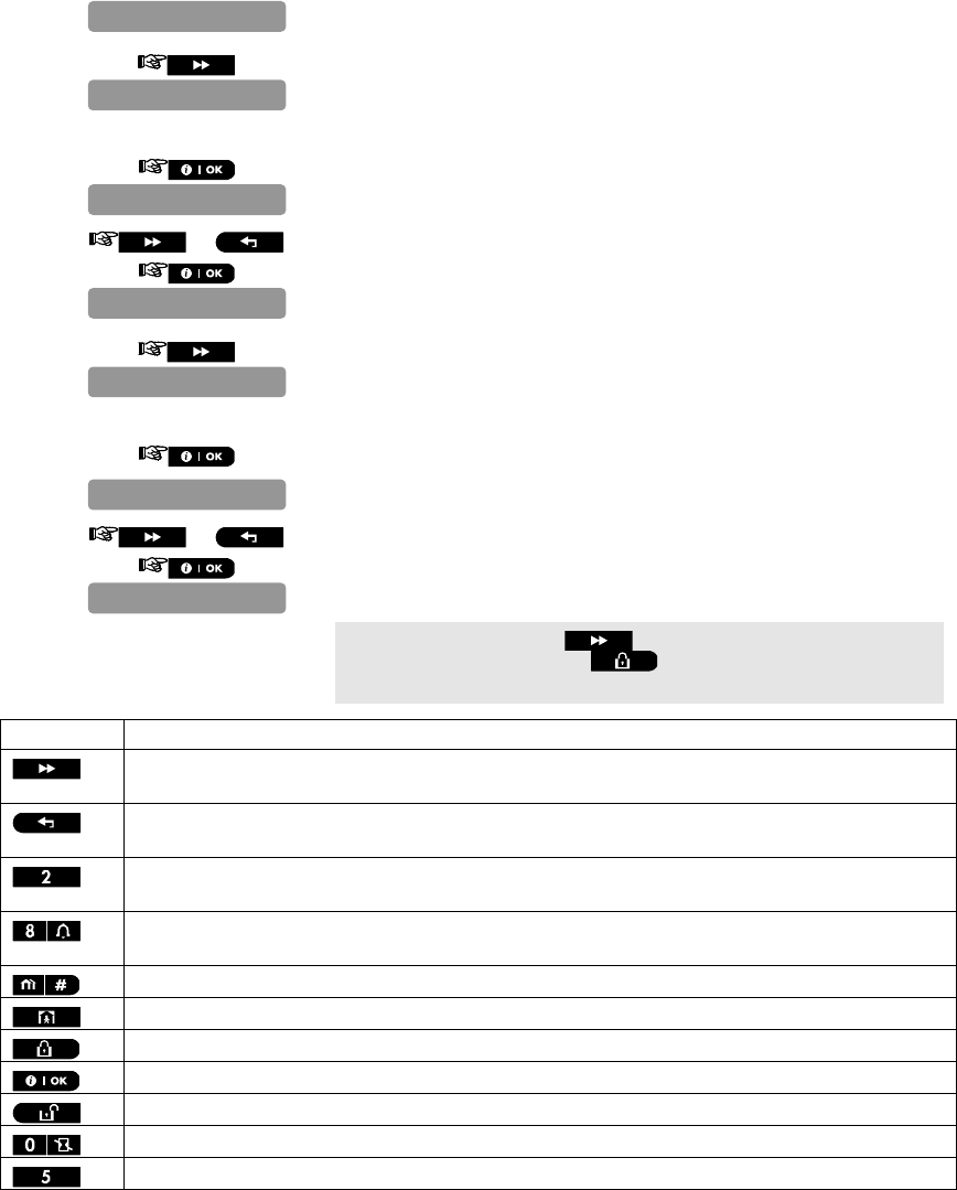
Key Functionality
Moves the cursor from left to right.
Long press for speed.
Moves the cursor from right to left.
Long press for speed.
Scrolls upward the sequence of inserted digits.
Long press for speed.
Scrolls downward the sequence of inserted digits.
Long press for speed.
Places cursor to extreme right position of edit string and shows the last 16 digits of edit string.
Reverts to previous or top menu without saving the edit string.
Reverts to "<OK> TO EXIT" without saving the edit string.
Saves and reverts to previous menu.
Clears all digits to the right of cursor.
Clears one digit by cursor.
Selects between uppercase or lowercase digits.
4.7.3 Configuring Event Reporting to Monitoring Station.
Here you determine which types of event will be reported to Monitoring Stations. Due to lack of space in the
display, abbreviations are used: alarm is “alrm”, alert is “alrt” and open/close is “o/c”. The asterisk () is a
SESSION TIMEOUT
FORCE HOME NTWK.
off on timeout
SESSION TIMEOUT
disable
FORCE HOME NTWK.
PIN CODE
D-302756 35
separator between events reported to Monitoring Station 1 and events reported to Monitoring Station 2.
Messages are divided by type into the following groups:
Group Abbr. Events Reported
Alarms alrm Fire, Burglary, Panic, Tamper
Open/close o/c Arming AWAY, Arming HOME, Disarming
Alerts Alrt No-activity, Emergency, Latchkey
Maintenance - Low-battery AC failure
"Alarm" group has the highest priority and "Alert" group has the lowest priority.
The selectable options are as follows:
Plan name Sent to center 1 Sent to center 2
"all -o/c backup" All but open/close All but open/close if center 1 doesn’t respond
"all all" All All
"all-o/c all -o/c " All but open/close All but open/close
"all –o/c o/c " All but open/close Open/close
"all (–alrt) alrt" All but alerts Alerts
"alrm all (–alrm)" Alarms All but alarms
"disable report" Nothing Nothing
"all backup" All All if cent. 1 doesn’t respond
Note: “All” means that all 4 groups are reported and also trouble messages - sensor / system low battery, sensor
inactivity, power failure, jamming, communication failure etc.
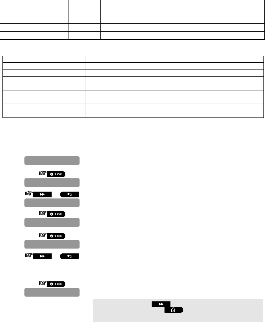
4.7.3.1 Configuring the Types of Events to be Reported
1. Repeat steps 1 to 4 of section 4.2 "Entering the Installer Menu".
2.
3. or
4.
5.
6. or Select between "all-o/c* backup", "all *all", "all-
o/c*all-o/c", "all-o/c*o/c", "all(-alrt)*alrt",
"alrm*all(-alrm)", "disable report" and "
a
ll
*backup".
7.
You can now press the button to take you to the "1st RPRT
METHOD" menu, or press the button to take you to "<OK> TO
EXIT".
4.7.3.2 Configuring the Communicators Report Sequence
Continue below from the previous section or repeat steps 1 to 4 of section 4.7.3.1 before continuing with the
REPORT EVENTS
all-o/c*backup
REPORT EVENTS
3:C.S. REPORTING
1:PSTN/GSM
DEFINE COMM.

36 D-302756
following instructions:
1.
Here you define the 1st priority of method used to report events.
2.
3. or Select between "disable", "cellular", "broadband" and "PSTN".
4.
5.
Here you define the 2nd priority method used to report events. If the
method defined to report events in the 1st priority fails, the control panel
will attempt to report using the method defined in the 2nd priority.
6.
7. or Select between "disable", "cellular", "broadband" and "PSTN".
8.
9.
Here you define the 3rd priority method used to report events. If the
method defined to report events in the 2nd priority fails, the control panel
will attempt to report using the method defined in the 3rd priority.
10.
11. or Select between "disable", "cellular", "broadband" and "PSTN".
12.
13.
Here you determine whether to report events using PSTN and cellular at
the same time instead of waiting for the 1st method to fail before trying
the 2nd method.
14.
15. or Select between "disable", "PSTN & broadband", and "PSTN &
cellular".
16.
You can now press the button to take you to the "
R
CVR 1
ACCOUNT#" menu, or press the button to take you to "<OK> TO
EXIT".
DUAL REPORTING
disable
3rd RPRT METHOD
3rd RPRT METHOD
2nd RPRT METHOD
2nd RPRT METHOD
1st RPRT METHOD
DUAL REPORTING
disable
REPORT EVENTS
disable
disable
1st RPRT METHOD
D-302756 37
4.7.3.3 Configuring Account Numbers to be Reported to the Monitoring Station
Continue below from the previous section or repeat steps 1 to 4 of section 4.7.3.1 before continuing with the
following instructions:
1. or
Here you enter the number that will identify your specific alarm control
system to the 1st Monitoring Station. The number consists of 6
hexadecimal digits.
2.
3. 1st RCVR ACC. NO. Enter the first receiver account number.
4.
5.
Here you enter the number that will identify your system to the 2nd
Monitoring Station. The account number consists of 6 hexadecimal digits.
6.
7. 2nd RCVR ACC. NO. Enter the second receiver account number.
8.
You can now press the button to take you to the "PSTN/GSM
RCVR 1" menu, or press the button to take you to "<OK> TO
EXIT".
4.7.3.4 Configuring the Monitoring Station's Telephone Numbers and IP Addresses
This mode allows you to adapt the telephone communication parameters to the local requirements.
Continue below from the previous section or repeat steps 1 to 4 of section 4.7.3.1 before continuing with the
following instructions:
1. or
Here you program the telephone number of the 1st Monitoring Station
(including area code, 16 digit max.) to which the system will report the
event groups defined in Report Events.
2.
Enter the telephone number of the first PSTN/GSM receiver (for further
details see the table at the end of this section).
3.
4.
Here you program the telephone number of the 2nd Monitoring Station
(including area code, 16 digit max.) to which the system will report the event
groups defined in Report Events.
5.
PSTN/GSM RCVR 2
PSTN/GSM RCVR 1
REPORT EVENTS
PSTN/GSM RCVR 1
RCV 2 ACCOUNT#
RCV 2 ACCOUNT#
RCV 1 ACCOUNT#
REPORT EVENTS
2nd acc. #001234
1st acc. #001234
RCVR 1 ACCOUNT#
38 D-302756
Enter the telephone number of the second PSTN/GSM receiver (for
further details see the table at the end of this section).
6.
7.
Here you enter the IP address of the IP receiver that is located in the 1st
Monitoring Station.
8.
Enter the IP address of the first IP receiver (for further details see the
table at the end of this section).
9.
10.
Here you enter the IP address of the IP receiver that is located in the 2nd
Monitoring Station.
11.
Enter the IP address of the second IP receiver (for further details see the
table at the end of this section).
12.
13.
Here you enter the telephone number of the SMS receiver that is located
in the 1st Monitoring Station.
14.
Enter the telephone number of the first SMS receiver (for further details
see the table at the end of this section).
15.
16.
Here you enter the telephone number of the SMS receiver that is located
in the 2nd Monitoring Station.
17.
Enter the telephone number of the second SMS receiver (for further
details see the table at the end of this section).
18.
You can now press the button to take you to the "PSTN RPRT
FORMAT" menu, or press the button to take you to "<OK> TO
EXIT".
Compatible Monitoring Station receivers are:
Osborne-Hoffman model 2000, Ademco Model 685, FBII Model CP220, Radionics Model D6500, Sur-
Gard Model SG-MLR2-DG and Silent Knight Model 9500.
IMPORTANT: In telephone number locations and account number locations, you may be required to enter
hexadecimal digits. In telephone number locations, these digits are used as codes to control the dialer:
SMS RCVR2
SMS RCVR2
SMS RCVR1
SMS RCVR1
IP RCVR 2
000.000.000.000
IP RCVR 2
IP RCVR 1
IP RCVR 1
000.000.000.000
PSTN/GSM RCVR 2
D-302756 39
Hex.Digit Keying
Sequence Code
Significance
A <#>
<0> Applicable only at the beginning of a number - the dialer waits 10
seconds or waits for dial tone, whichever comes first and then dials.
D <#>
<3> Applicable only at the beginning of a number - the dialer waits 5 seconds
for dial tone and goes on hook if none is received.
E <#>
<4> Applicable only in the middle of the number - the dialer waits 5 seconds
F <#>
<5> Not applicable in phone numbers
Note: A "+" can be entered at the beginning of the line by pressing and then .
To enter a series of digits, use the following keys:
<Numeric keypad> - to enter the number
- moves the cursor from left to right
- moves the cursor from right to left
- deletes everything after the cursor (to the right)
4.7.3.5 Configuring the Report Method (Protocol) to Monitoring Station
Continue below from the previous section or repeat steps 1 to 4 of section 4.7.3.1 before continuing with the
following instructions:
1. or
Here you select the reporting format used by the control panel to report
events to Monitoring Stations.
2.
3. or Select between "SIA", "4/2 1900/1400", "4/2 1800/2300",
"Scancom", "SIA text" and "contact ID".
4.
5.
Here you select the pulse rate at which data will be sent to Monitoring
Stations if any one of the 4/2 formats has been selected in PSTN Report
Format.
6.
7. or Select between "10 pps", "20 pps", "33 pps" and "40 pps".
8.
You can now press the button to take you to the "PSTN RPRT
RETRY" menu, or press the button to take you to "<OK> TO
EXIT".
4.7.3.6 Configuring the Number of Retry Attempts
Continue below from the previous section or repeat steps 1 to 4 of section 4.7.3.1 before continuing with the
following instructions:
REPORT EVENTS
4/2 PULSE RATE
4/2 PULSE RATE
PSTN RPRT FORMAT
REPORT EVENTS
20 pps
SIA
PSTN RPRT FORMAT

40 D-302756
1. or
Here you determine the number of times the communicator will dial the
Monitoring Station’s number via PSTN.
2.
3. or Select between "2 attempts", "4 attempts", "8 attempts", "
1
2
attempts" and "16 attempts".
4.
5.
Here you determine the number of times the communicator will try to
report via a cellular group (GPRS, GSM and SMS) to the Monitoring
Station.
6.
7. or Select between "2 attempts", "4 attempts", "8 attempts", "
1
2
attempts" and "16 attempts".
8.
9.
Here you determine the number of times the communicator will try to
report via the PowerLink Broadband Module communication to the
Monitoring Station.
10.
11. or Select between "2 attempts", "4 attempts", "8 attempts", "
1
2
attempts" and "16 attempts".
12.
You can now press the button to take you to the "AUTO TEST
TIME" menu, or press the button to take you to "<OK> TO
EXIT".
4.7.3.7 Configuring the Auto Test Report
Continue below from the previous section or repeat steps 1 to 4 of section 4.7.3.1 before continuing with the
following instructions:
1. or
Here you determine the time at which the telephone line will be tested
and reported to the Monitoring Station.
2.
Enter the auto test time.
3.
AUTO TEST TIME
REPORT EVENTS
test time 12:00P
AUTO TEST TIME
LAN RPRT RETRY
LAN RPRT RETRY
4 attempts
GSM RPRT RETRY
GSM RPRT RETRY
PSTN RPRT RETRY
4 attempts
4 attempts
PSTN RPRT RETRY
D-302756 41
4.
Here you determine the time interval between consecutive telephone line
test messages sent to the Monitoring Station. The control panel performs
this at regular intervals to verify proper communications.
5.
6. or Select between "test OFF", "test every 1 d", "test every 2 d",
"test every 5 d", "test every 7 d", "test every 14 d", "test
every 30 d" and "test every 5 h".
7.
8.
9.
Here you determine if the PSTN telephone line disconnection will be
reported or not and determine the delay between detection of line
disconnection and the failure reporting. If the telephone line is
disconnected, the event "tel line fail" will be stored in the event log.
10.
11. or Select between "immediately", "5 minutes", "30 minutes", "
6
0
minutes", "180 minutes" and "don't report".
12.
13.
Here you determine if the GSM/GPRS line disconnection will be reported
or not and determine the delay between detection of line disconnection
and report failure. If the telephone line is disconnected, the event "GSM
line fail" will be stored in the event log.
14.
15. or Select between "2 minutes", "5 minutes", "30 minutes", "
6
0
minutes", "180 minutes" and "don't report".
16.
17.
Here you determine if the PowerLink Broadband Module line
disconnection will be reported or not and determine the delay between
detection of line disconnection and report failure. If the telephone line is
disconnected, the event "PLNK line fail" will be stored in the event log.
18.
19. or Select between "2 minutes", "5 minutes", "30 minutes", "
6
0
minutes", "180 minutes" and "don't report".
broadband
don’t report
GSM/GPRS
GSM/GPRS
don’t report
PSTN
PSTN
AUTO TEST CYCLE
AUTO TEST CYCLE
LINE FAIL REPORT
immediately
test OFF

42 D-302756
20.
21.
You can now press the button to take you to the "PSTN UP/DOWN"
menu (see Configuring Remote Programming Access Permissions), or
press the button to take you to "<OK> TO EXIT".
4.7.3.8 Configuring the Event Types to be Reported to the Monitoring Station
Continue below from the previous section or repeat steps 1 to 4 of section 4.7.3.1 before continuing with the
following instructions:
1. or
Here you determine whether the system will report whenever 2 or more
events (confirmed alarm) occur during a specific period.
2.
3. or Select between "disable report", "enable + bypass" and
"enable report".
4.
5.
Here you enable or disable the “recent closing” report, that is sent to the
Monitoring Station if an alarm occurs within 2 minutes from the expiry of
the exit delay.
6.
7. or Select between "recent cl. OFF" and "recent cl. ON".
8.
9.
Here you determine whether a zone restore will be reported or not.
10.
11. or Select between "report restore" and "don't report".
12.
13.
Here you determine whether the Monitoring Station will receive a
message if the system is inactive (not armed) during a defined period
(days).
SYS INACT REPORT
ZONE RESTORE
RECENT CLOSE
recent cl. OFF
RPRT CNFRM ALARM
ZONE RESTORE
report restore
RECENT CLOSE
REPORT EVENTS
disable report
RPRT CNFRM ALARM
LINE FAIL REPORT
broadband
D-302756 43
14.
15. or Select between "disable", "rep. after 7d", " rep. after 14d ",
" rep. after 30d", and "rep. after 90d".
16.
You can now press the button to take you to the "REPORT
EVENTS" menu (see section 4.7.2.1), or press the button to take
you to "<OK> TO EXIT".
4.7.4 Configuring Event Reporting to Users
A. To Enable Report to Users
1. Repeat steps 1 to 4 of section 4.2 "Entering the Installer Menu".
2.
3. or
4.
5.
B. To Configure Event Types to be Reported to User
Here you determine which event groups will be reported to private telephone subscribers.
Term Description
"all" All messages
"all (-op/cl)" All messages, except open/close
"all (-alerts)" All messages, except alerts
"alarms" Alarm messages
"alerts" Alert messages
"op/cl" Open/close
"disable report" No message will be reported
Note: “All” means all events including the L. BAT and AC FAIL trouble messages.
Note: All the above options can be reported to private telephone subscribers by SMS. When Voice Report is
enabled alarms and alerts only can be reported.
The following siren signal will be sent to private telephone upon event reporting:
FIRE: ON - ON - ON - pause.... (- - - - - - ......).
BURGLAR: ON continuously ( ...)
EMERGENCY/LATCHKEY: 2-tone siren; like an ambulance.
6. or Select between "disable report", "all", "all (-op/cl)", "all(-
alerts)", "alarms", "alerts" and "op/cl".
7.
REPORT TO PRVT
disable report
REPORT TO PRVT
4:PRIVATE REPORT
1:PSTN/GSM
DEFINE COMM.
SYS INACT REPORT
disable
44 D-302756
You can now press the button to take you to the "
V
OICE
REPORT" menu, or press the button to take you to "<OK> TO
EXIT".
C. To Configure Event Types to be Reported to User
8.
9.
10.
11. 1st PRIVATE TEL.
NO. Enter the first private telephone number (including area code, if required)
of the private subscriber to which the system will report the event groups
defined in Report To Private.
12.
13.
14.
15. 2nd PRIVATE TEL.
NO. Enter the second private telephone number (including area code, if
required) of the private subscriber to which the system will report the event
groups defined in Report To Private.
16.
17.
18.
19. 3rd PRIVATE TEL.
NO. Enter the third private telephone number (including area code, if required)
of the private subscriber to which the system will report the event groups
defined in Report To Private.
20.
21.
22.
23. 4th PRIVATE TEL.
NO. Enter the fourth private telephone number (including area code, if required)
of the private subscriber to which the system will report the event groups
defined in Report To Private.
24.
25.
Here you determine the number of times the communicator will dial the
called party’s number (private telephone).
26.
4th private tel#
4th private tel#
3rd private tel#
2nd private tel#
2nd private tel#
1st private tel#
Redial attempts
3rd private tel#
1st private tel#
VOICE REPORT
D-302756 45
27. or Select between "1 attempt", "2 attempts", "3 attempts" and "
4
attempts".
Attention! A maximum of 2 dialing attempts is permitted by the
Australian Telecommunication Authority.
28.
29.
Here you determine whether the system will use the single acknowledge
or the all acknowledge mode when reporting to private telephones.
Note: In the single acknowledge mode, receiving an acknowledge signal
from a single telephone is sufficient to consider the current event closed
and call off the communication session. The remaining telephones serve
for backup purposes only. In the all acknowledge mode, an acknowledge
signal must be received from each telephone before the current event is
considered reported.
30.
31. or Select between "single ack" and "all ack".
32.
33.
You can now press the button to take you to the "SMS REPORT
TEL#" menu (see the next section), or press the button to take
you to "<OK> TO EXIT".
D. To Configure Reports to User by SMS
34.
35.
36.
37. 1st SMS TEL. NO. Enter the first SMS phone number (including area code, 16 digits max.)
to which pre-selected event types will be reported.
38.
39.
40.
41. 2nd SMS TEL. NO. Enter the second SMS phone number (including area code, 16 digits
max.) to which pre-selected event types will be reported.
2nd SMS tel#
1st SMS tel#
VOICE REPORT
1st SMS tel#
SMS REPORT TEL#
VOICE REPORT
Tel. acknowledge
Redial attempts
single ack
Tel. acknowledge
3 attempts
46 D-302756
42.
43.
44. 3rd SMS TEL. NO. Enter the third SMS phone number (including area code, 16 digits max.)
to which pre-selected event types will be reported.
45.
46.
47.
48. 4th SMS TEL. NO. Enter the fourht SMS phone number (including area code, 16 digits max.)
to which pre-selected event types will be reported.
49.
You can now press the button to take you to the "1st private
tel#" menu (see step C. To Configure Event Types to be Reported to
User), or press the button to take you to "<OK> TO EXIT".
4.8 Security System Configuration
4.8.1 Enable Cross Zoning
Here you determine whether cross zoning will be active or inactive. Cross zoning is a method used to counteract
false alarms - an alarm will not be initiated unless two adjacent zones are violated within a 30-second time limit.
This feature is active only when arming AWAY and only with zone couples from zone No. 18 to 27 (18 and 19,
20 and 21, etc.). You may use any one of these zone couples to create a “cross-zoned” area.
Note: If one of two crossed zones is bypassed (see Para. 4.3.5), the remaining zone will function independently.
Note: Every 2 crossed zones must be of the allowed zone type (Interior, Perimeter, Perimeter follower).
The options are: cross zone ON and cross zone OFF (default).
Cross zoning is not applicable in Entry/ Exit zones and 24h zones (Fire, Emergency, 24h audible, 24h silent).
To Enable Cross Zoning
1. Repeat steps 1 to 4 of section 4.2 "Entering the Installer Menu".
2.
3. or
4.
5. or Select between "cross zone OFF" and "cross zone ON".
6.
cross zone OFF
14:CROSS ZONING
01:ENTRY DELAY 1
DEFINE PANEL
4th SMS tel#
4th SMS tel#
3rd SMS tel#
3rd SMS tel#
2nd SMS tel#
D-302756 47
You can now press the or button to program any other
menu in "DEFINE PANEL" or press the button to take you to "<OK>
TO EXIT".
4.8.2 Configuring Swinger Stop
Here you determine the number of times each zone is allowed to initiate an alarm within a single
arming/disarming period (including tamper & power failure events of detectors, PowerMaster-10, wireless siren,
etc.). If the alarms number from a specific zone exceeds the programmed number, the control panel
automatically bypasses the zone to prevent recurrent siren noise and nuisance reporting to the Monitoring
Station. The zone will be reactivated upon disarming, or 48 hours after having been bypassed (if the system
remains armed).
Available options are: shut after 1 (default), shut after 2 (default in USA), shut after 3 and no shutdown.
Note: To comply with EN requirements, the swinger stop should be set to 3.
To Configure Swinger Stop
1. Repeat steps 1 to 4 of section 4.2 "Entering the Installer Menu".
2.
3. or
4.
5. or Select between "shut after 1", "shut after 2", "shut after 3"
and "no shutdown".
6.
You can now press the or button to program any other
menu in "DEFINE PANEL" or press the button to take you to "<OK>
TO EXIT".
4.8.3 Enable Monitoring of Activity at Home
Here you determine the time limit for reception of signals from sensors used to monitor the activity of sick,
elderly or disabled people. If no sensor detects and reports movement at least once within the defined time limit,
a “not-active” alert is initiated.
Options: 3, 6, 12, 24, 48, 72 hours and no act disable (default).
To Configure Monitoring of Activity at Home
1. Repeat steps 1 to 4 of section 4.2 "Entering the Installer Menu".
2.
01:ENTRY DELAY 1
DEFINE PANEL
13:SWINGER STOP
shut after 1
13:SWINGER STOP
01:ENTRY DELAY 1
DEFINE PANEL
14:CROSS ZONING
48 D-302756
3. or
4.
5. or Select between "no act disable", "3 h", "6 h", "12 h", "24 h", "
4
8
h", and "72 h".
6.
You can now press the or button to program any other
menu in "DEFINE PANEL" or press the button to take you to "<OK>
TO EXIT".
4.8.4 Configuring Alarm Cancel Period
Here you determine the ”cancel alarm” period that starts upon reporting an alarm to the Monitoring Station. If the
user disarms the system within that time period, a “cancel alarm” message is sent to the Monitoring Station.
Available options are: cancel time 1 m, cancel time 5 m (default), cancel time 15 m, cancel time 60 m,
cancel time 4 hours and also cancel inactive (default in USA).
Note: To comply with CP-01 requirements, "1 minute" option is not available .
To Configure the Alarm Cancel Period
1. Repeat steps 1 to 4 of section 4.2 "Entering the Installer Menu".
2.
3. or
4.
5. or Select between "cancel time 1 m", "cancel time 5 m", "
c
ancel
time 15 m", "cancel time 60 m", "cancel time 4 h", and
"cancel inactive".
6.
You can now press the or button to program any other
menu in "DEFINE PANEL" or press the button to take you to "<OK>
TO EXIT".
4.8.5 Configuring Power Failure Threshold Period
Here you determine the time interval between AC power failure occurrence and the failure reporting.
Options: 5 minutes (default), 30 minutes, 60 minutes or 180 minutes.
Note: To comply with EN requirements, set to 60 min. max.
06:ALARM CANCEL
cancel time 5 m
06:ALARM CANCEL
01:ENTRY DELAY 1
DEFINE PANEL
21:NOT ACTIVE
no act disable
21:NOT ACTIVE
D-302756 49
To Configure the Power Failure Threshold Period
1. Repeat steps 1 to 4 of section 4.2 "Entering the Installer Menu".
2.
3. or
4.
5. or Select between "5 minutes", "30 minutes", "60 minutes", and "180
minutes".
6.
You can now press the or button to program any other
menu in "DEFINE PANEL" or press the button to take you to "<OK>
TO EXIT".
4.8.6 Configuring Abort Time
Here you select the length of time allowed by the system to abort an alarm (not applicable to alarms from FIRE, 24H
SILENT and EMERGENCY zones). The PowerMaster-10 is programmed to provide an “abort interval” that starts upon
detection of an event. During this interval, the buzzer sounds a warning but the siren remains inactive and the alarm is
not reported. If the user disarms the system within the allowed abort interval, the alarm is aborted.
Available options are: 00s (default in USA), 15s, 30s (default), 45s, 60s, 2m, 3m and 4m.
Note: To comply with CP-01 requirements, "60s", "3m" and "4m" options are not available.
Note: To comply with UL requirements, the abort time must not exceed 45 sec.
To Configure the Abort Time
1. Repeat steps 1 to 4 of section 4.2 "Entering the Installer Menu".
2.
3. or
4.
5. or Select between "abort time 00s", "abort time 15s", "abort
time 30s", "abort time 45s", "abort time 60s", "abort time
2m", "abort time 3m" and "abort time 4m".
6.
You can now press the or button to program any other
menu in "DEFINE PANEL" or press the button to take you to "<OK>
TO EXIT".
05:ABORT TIME
abort time 30s
05:ABORT TIME
01:ENTRY DELAY 1
DEFINE PANEL
34:AC FAIL REP
5 minutes
34:AC FAIL REP
01:ENTRY DELAY 1
DEFINE PANEL
50 D-302756
4.8.7 Configuring a Confirmed Alarm
Here you determine that if 2 successive alarms will occur during a specific period, the second alarm will be
considered as a confirmed alarm for confirmed alarm reporting, (see par. 4.6.3.2 "Configuring the Event Types
to be Reported").
Options: disable (default in USA), 30 min., 45 min., 60 min. (default), or 90 min.
To Configure a Confirmed Alarm
1. Repeat steps 1 to 4 of section 4.2 "Entering the Installer Menu".
2.
3. or
4.
5. or Select between "disable", "30 minutes", "45 minutes", "
6
0
minutes", and "90 minutes".
6.
You can now press the or button to program any other
menu in "DEFINE PANEL" or press the button to take you to "<OK>
TO EXIT".
4.8.8 Enable Alarm upon Detection of Jammed or Missing Device
Here you determine whether an alarm will be initiated (siren / report) when there is a supervision / jamming
failure during AWAY arming state.
Available options are: EN standard and other (default). When "EN standard" is selected, if there is
supervision / jamming failure during AWAY arming, the siren is activated and the events are reported as
tamper events. When "Other" is selected, there is no such activity during AWAY arming.
To Enable an Alarm Upon Detection of a Jammed or Missing Device
1. Repeat steps 1 to 4 of section 4.2 "Entering the Installer Menu".
2.
3. or
4.
5. or Select between "EN standard", and "other".
6.
30:BELL/REP.OPT
other
30:BELL/REP.OPT
01:ENTRY DELAY 1
DEFINE PANEL
33:CONFIRM TIME
60 minutes
33:CONFIRM TIME
01:ENTRY DELAY 1
DEFINE PANEL
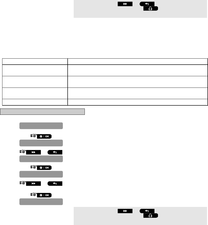
D-302756 51
You can now press the or button to program any other
menu in "DEFINE PANEL" or press the button to take you to "<OK>
TO EXIT".
4.8.9 Configuring the Jamming Detection
Here you determine whether jamming (interfering transmissions, on the radio channel used by the system) will
be detected and reported or not.
If a jam detection option is selected, the system does not allow arming under the relevant jamming conditions.
Jam Detection Options
Option Detection and Reporting when
UL 20/20
(USA standard) There is continuous 20 seconds of jamming
EN 30/60
(Europe standard) There is an accumulated 30 seconds of jamming within 60 sec.
class 6 (30/60)
(British standard) Like EN (30/60) but the event will be reported only if the jamming
duration exceeds 5 minutes.
Disable (default) (No jamming detection and reporting).
To Configure the Jamming Detection
1. Repeat steps 1 to 4 of section 4.2 "Entering the Installer Menu".
2.
3. or
4.
5. or Select between "UL 20/20", "EN 30/60", "class 6 (30/60)" and
"disable".
6.
You can now press the or button to program any other
menu in "DEFINE PANEL" or press the button to take you to "<OK>
TO EXIT".
4.8.10 Configuring Whether a Missing Device Causes the System to Become
"NOT READY"
Here you determine if the system will be in NOT READY status when there is a supervision failure. In the "in
supervision" mode, the system will be in NOT READY status if during the last 20 minutes a supervision
message was not received. Options: normal (default) and in supervision.
Note: To comply with EN requirements, "in supervision" must be selected.
19:JAM DETECT
disable
19:JAM DETECT
01:ENTRY DELAY 1
DEFINE PANEL
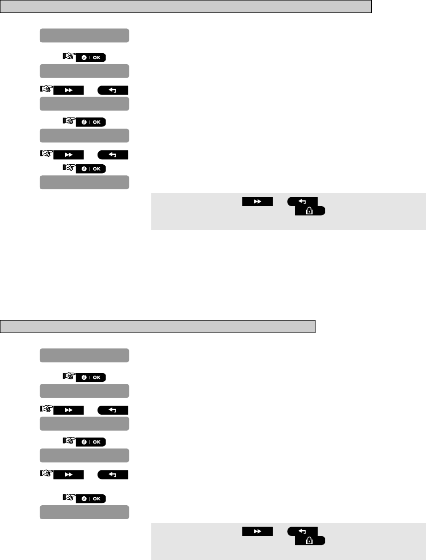
52 D-302756
To Configure whether a missing device causes the system to become "NOT READY"
1. Repeat steps 1 to 4 of section 4.2 "Entering the Installer Menu".
2.
3. or
4.
5. or Select between "normal", and "in supervision".
6.
You can now press the or button to program any other
menu in "DEFINE PANEL" or press the button to take you to "<OK>
TO EXIT".
4.8.11 Configuring the Time Period by which a Device is considered Missing
Here you determine the time limit for reception of supervision reports from various supervised wireless devices.
If any device does not report at least once within the selected time limit, an “INACTIVITY” alert is initiated.
The options are: 1, 2, 4, 8, 12 hours (default) and disable.
Note: To comply with EN requirements, 1 or 2 hours must be selected.
To Configure the Time Period by which a Device is Considered Missing
1. Repeat steps 1 to 4 of section 4.2 "Entering the Installer Menu".
2.
3. or
4.
5. or Select between "superv time 1h", "superv time 2h", "
s
uperv
time 4h", "superv time 8h", "superv time 12h" and "disable".
6.
You can now press the or button to program any other
menu in "DEFINE PANEL" or press the button to take you to "<OK>
TO EXIT".
15:SUPERVISION
superv time 12h
15:SUPERVISION
01:ENTRY DELAY 1
DEFINE PANEL
16:NOT READY
normal
16:NOT READY
01:ENTRY DELAY 1
DEFINE PANEL
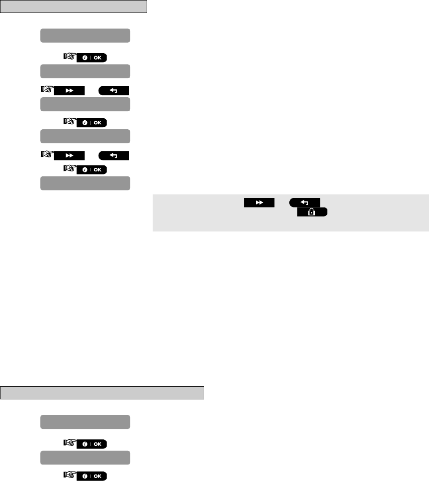
D-302756 53
4.9 Arming/Disarming Options And Exit/Entry Delay
4.9.1 Configuring Exit Modes
Here you determine exit delay mode options. Three types of exit delay modes are available:
restart exit - Exit delay restarts when the door is reopened during exit delay. The restart occurs once only.
Restarting the exit delay is helpful if the user re-enters immediately after going out to retrieve an item that he left
behind.
off by door - When the door is closed, the exit delay is automatically terminated (even if the defined exit delay
was not completed).
normal (default) - The exit delay is exactly as defined, regardless of whether the door is open or closed.
To Configure the Exit Modes
1. Repeat steps 1 to 4 of section 4.2 "Entering the Installer Menu".
2.
3. or
4.
5. or Select between "restart exit", "off by door", and "normal".
6.
You can now press the or button to program any other
menu in "DEFINE PANEL" or press the button to take you to "<OK>
TO EXIT".
4.9.2 Configuring Entry Delays Duration
Two different entry delays allow the user to enter the protected site (while the system is in the armed state) via 2
specific doors and routes without causing an alarm.
Following entry, the user must disarm the control panel before the entry delay expires. Slow-rate warning beeps
start sounding once the door is opened, until the last 10 seconds of the delay, during which the beeping rate
increases. Locations No. 1 (entry delay 1) and 2 (entry delay 2) allow you to program the length of these delays.
Available options for each delay are: "00s", "15s" (default for entry delay 2), "30s" (default for entry delay 1),
"45s", "60s", "3m" and "4m".
Note: To comply with CP-01 requirements, "00s" and "15s" options are not available.
Note: To comply with EN requirements, the entry delay must not exceed 45 sec.
Note: To comply with UL requirements, the entry delay must not exceed 45 sec.
To Configure the Duration of the Entry Delays
1. Repeat steps 1 to 4 of section 4.2 "Entering the Installer Menu".
2.
*
3.
01:ENTRY DELAY 1
DEFINE PANEL
09:EXIT MODE
normal
09:EXIT MODE
01:ENTRY DELAY 1
DEFINE PANEL

54 D-302756
4. or Select between "entry dly1 00s", "entry dly1 15s", "
e
ntry
dly1 30s", "entry dly1 45s", "entry dly1 60s", "entry dly1
3m" and "entry dly1 4m".**
5.
* Press the button for "02:ENTRY DELAY 2".
** In the "02:ENTRY DELAY 2" menu, the PowerMaster-10 display will
read "entry dly2…".
You can now press the or button to program any other
menu in "DEFINE PANEL" or press the button to take you to "<OK>
TO EXIT".
4.9.3 Configuring Exit Delay Duration
An exit delay allows the user to arm the system and leave the protected site via specific routes and doors
without causing an alarm. Slow-rate warning beeps start sounding once the arming command has been given,
until the last 10 seconds of the delay, during which the beeping rate increases. Location No. 3 allows
programming of the exit delay length. Available options are: 30s, 60s (default), 90s, 120s, 3m, and 4m.
Note: To comply with CP-01 requirements, "30s" option is not available.
Note: To comply with UL requirements, the exit delay must not exceed 120 sec.
To Configure the Exit Delay Duration
1. Repeat steps 1 to 4 of section 4.2 "Entering the Installer Menu".
2.
3. or
4.
5. or Select between "exit delay 30s", "exit delay 60s", "
e
xit
delay 90s", "exit delay 120s", "exit delay 3m"and "
e
xit
delay 4m".
6.
You can now press the or button to program any other
menu in "DEFINE PANEL" or press the button to take you to "<OK>
TO EXIT".
4.9.4 Enabling Quick Arm
Here you determine whether the user will be allowed to perform quick arming or not. Once quick arming is
permitted, the control panel does not request a user code before it arms the system.
The two options are: quick arm ON (default in USA) and quick arm OFF (default).
To Enable Quick Arm
03:EXIT DELAY
exit delay 60s
03:EXIT DELAY
01:ENTRY DELAY 1
DEFINE PANEL
09:EXIT MODE
entry dly1 30s
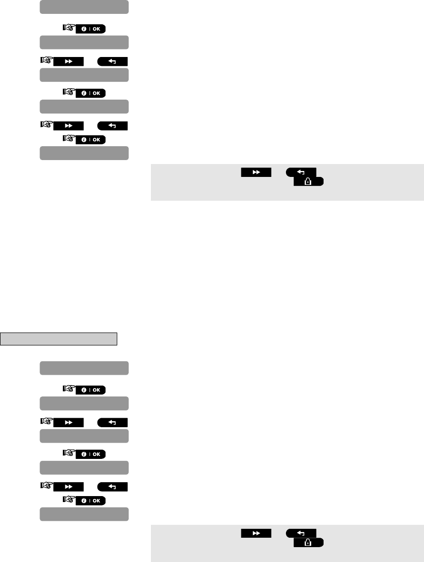
D-302756 55
1. Repeat steps 1 to 4 of section 4.2 "Entering the Installer Menu".
2.
3. or
4.
5. or Select between "quick arm ON", and "quick arm OFF".
6.
You can now press the or button to program any other
menu in "DEFINE PANEL" or press the button to take you to "<OK>
TO EXIT".
4.9.5 Configuring Bypassing Zones
Here you permit either manual bypassing of individual zones (through the USER SETTINGS menu), or allow the
system to "force arm" (perform automatic bypassing) of open zones during the exit delay. If desired, press the
arming key again if you want to eliminate the protest tone that sounds during forced arming. If a zone is open
and forced arming is not permitted, “NOT READY” is displayed and the system does not arm (the “Sad Melody”
will sound). If "no bypass" is selected, neither manual bypassing nor force arming is allowed.
Options: manual bypass (default in USA), force arm and no bypass (default).
Note: To comply with EN requirements, "manual bypass" or "force arm" must be selected.
Note: The option "force arm" is not applicable in the UK.
To Configure Bypass
1. Repeat steps 1 to 4 of section 4.2 "Entering the Installer Menu".
2.
3. or
4.
5. or Select between "manual bypass", "force arm" and "no bypass".
6.
You can now press the or button to program any other
menu in "DEFINE PANEL" or press the button to take you to "<OK>
TO EXIT".
08:BYPASS
no bypass
08:BYPASS
01:ENTRY DELAY 1
DEFINE PANEL
07:QUICK ARM
quick arm OFF
07:QUICK ARM
01:ENTRY DELAY 1
DEFINE PANEL
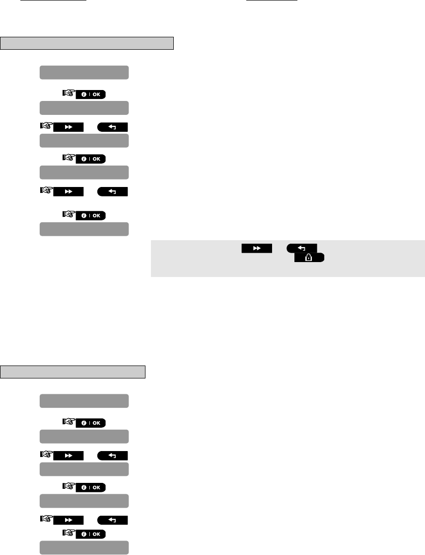
56 D-302756
4.9.6 Configuring Panic Alarm Activation
Here you determine whether the user will be allowed to initiate a panic alarm by simultaneous pressing of either
the two panic buttons (on the keypad / wireless commander) or away + home (on a keyfob transmitter). Audible
panic activates the siren and simultaneously transmits a message via telephone. Silent panic only transmits a
message via telephone.
The options are: silent panic, audible panic (default) and disable panic.
To Configure Panic Alarm Activation
1. Repeat steps 1 to 4 of section 4.2 "Entering the Installer Menu".
2.
3. or
4.
5. or Select between "silent panic", "audible panic" and "disable
panic".
6.
You can now press the or button to program any other
menu in "DEFINE PANEL" or press the button to take you to "<OK>
TO EXIT".
4.9.7 Enabling Latchkey Arming
Here you determine whether the system can be armed in the latchkey mode. If the system is armed this way, a
“latchkey” message will be sent to specific telephones upon disarming by a “latchkey user” (users 5-8 or keyfob
transmitters 5-8). This mode is useful when parents at work want to be informed of a child’s return from school.
The options are: Latchkey ON and Latchkey OFF (default).
To Enable Latchkey Arming
1. Repeat steps 1 to 4 of section 4.2 "Entering the Installer Menu".
2.
3. or
4.
5. or Select between "Latchkey ON", and "Latchkey OFF".
6.
20:LATCHKEY
Latchkey OFF
20:LATCHKEY
01:ENTRY DELAY 1
DEFINE PANEL
12:PANIC ALARM
audible panic
12:PANIC ALARM
01:ENTRY DELAY 1
DEFINE PANEL
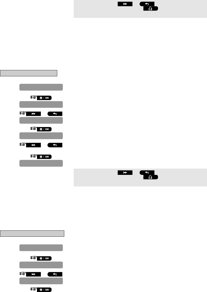
D-302756 57
You can now press the or button to program any other
menu in "DEFINE PANEL" or press the button to take you to "<OK>
TO EXIT".
4.10 User Interface Customization
4.10.1 Enabling Trouble Beeps
Under trouble conditions, the sounder emits a series of 3 short beeps once per minute. Here you determine
whether this special beeping sequence will be active, inactive, or just inactive at night (the range of “night” hours
is defined in the factory but is usually from 8 PM until 7 AM).
The 3 options are: enable beeps (default in USA), off at night (default) and disable beeps.
To Enable Trouble Beeps
1. Repeat steps 1 to 4 of section 4.2 "Entering the Installer Menu".
2.
3. or
4.
5. or Select between "enable beeps", "off at night" and "disable
beeps".
6.
You can now press the or button to program any other
menu in "DEFINE PANEL" or press the button to take you to "<OK>
TO EXIT".
4.10.2 Enabling Piezo Beeps
Here you determine whether warning beeps will sound or muted during exit and entry delays. An additional
option is to mute the warning beeps only when the system is armed “HOME”.
Options: enable beeps (default), off when home (default in USA) and disable beeps.
Note: When exit beeps are disabled toward the end of a delay, the happy (success) melody will sound.
To Enable Piezo Beeps
1. Repeat steps 1 to 4 of section 4.2 "Entering the Installer Menu".
2.
3. or
4.
10:PIEZO BEEPS
01:ENTRY DELAY 1
DEFINE PANEL
11:TROUBLE BEEPS
off at night
11:TROUBLE BEEPS
01:ENTRY DELAY 1
DEFINE PANEL
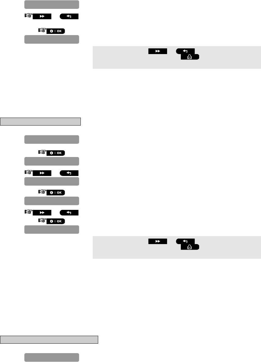
58 D-302756
5. or Select between "enable beeps", "off when home" and "disable
beeps".
6.
You can now press the or button to program any other
menu in "DEFINE PANEL" or press the button to take you to "<OK>
TO EXIT".
4.10.3 Enabling the Back Light
Here you determine whether the keypad back lighting will remain on at all times or will turn on when a key is
pressed and turn off within 10 seconds if no further keystrokes are sensed.
The two options are: always ON and OFF after 10 s (default).
To Enable the Back Light
1. Repeat steps 1 to 4 of section 4.2 "Entering the Installer Menu".
2.
3. or
4.
5. or Select between "OFF after 10s", and "always ON".
6.
You can now press the or button to program any other
menu in "DEFINE PANEL" or press the button to take you to "<OK>
TO EXIT".
4.10.4 Configuring the Disarm Option
Here you determine when it is possible to disarm the system:
A. Any time.
B. In AWAY mode, during entry delay, by using the PowerMaster-10 keypad or wireless sensor (keyfob).
C. In AWAY mode, during entry delay, by using a wireless device (keyfob) only (this is set as a default in UK to
comply with DD243).
D. During entry delay, or by using the PowerMaster-10 keypad in AWAY mode.
Options: any time (default), on entry wireless, entry + away kp (default in UK), or on entry all.
To Configure the Disarm Option
1. Repeat steps 1 to 4 of section 4.2 "Entering the Installer Menu".
DEFINE PANEL
22:BACK LIGHT
OFF after 10s
22:BACK LIGHT
01:ENTRY DELAY 1
DEFINE PANEL
10:PIEZO BEEPS
enable beeps
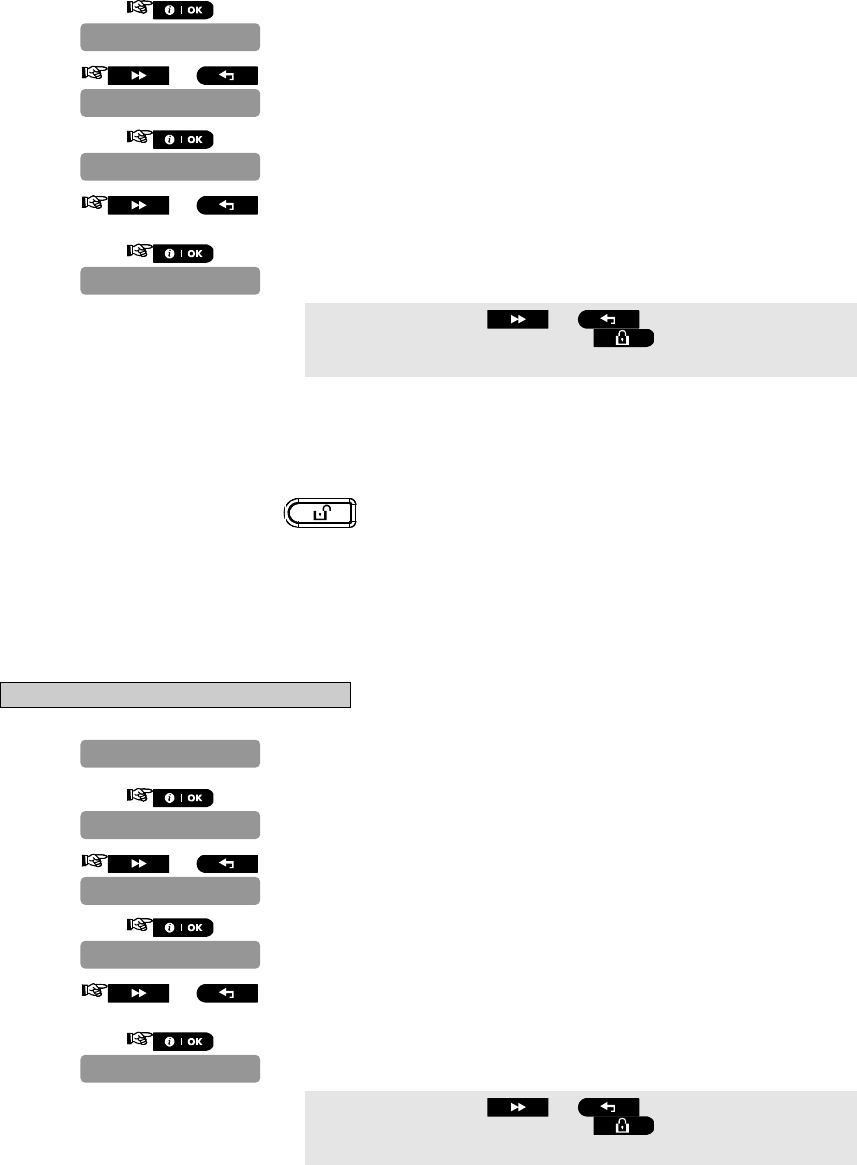
D-302756 59
2.
3. or
4.
5. or Select between "any time", "on entry wrless", "entry + away
kp" and "on entry all".
6.
You can now press the or button to program any other
menu in "DEFINE PANEL" or press the button to take you to "<OK>
TO EXIT".
4.10.5 Configuring the Screen Saver Options
Here you can determine that if no key is pressed during more than 30 seconds the display will read
“PowerMaster-10” (to prevent a possible intruder of knowing the system status). You can determine that normal
display will return after pressing the button followed by entering user code (Refresh by Code) or after
pressing any key (Refresh by Key).
If Refresh by Key is selected, the first pressing of any key (except Fire and Emergency) will cause normal display
return and the second press will perform the key function. Regarding the Fire and Emergency keys, the first key
press will cause normal display return and also will perform the Fire/Emergency function.
Options: scrn saver OFF (default), refresh by code, refresh by key.
Note: To comply with EN requirements, "refresh by code" must be selected.
To Configure the Screen Saver Option
1. Repeat steps 1 to 4 of section 4.2 "Entering the Installer Menu".
2.
3. or
4.
5. or Select between "scrn saver OFF", "refresh by Code", and
"refresh by Key".
6.
You can now press the or button to program any other
menu in "DEFINE PANEL" or press the button to take you to "<OK>
TO EXIT".
32:SCREEN SAVER
scrn saver OFF
32:SCREEN SAVER
01:ENTRY DELAY 1
DEFINE PANEL
29:DISARM OPTION
any time
29:DISARM OPTION
01:ENTRY DELAY 1
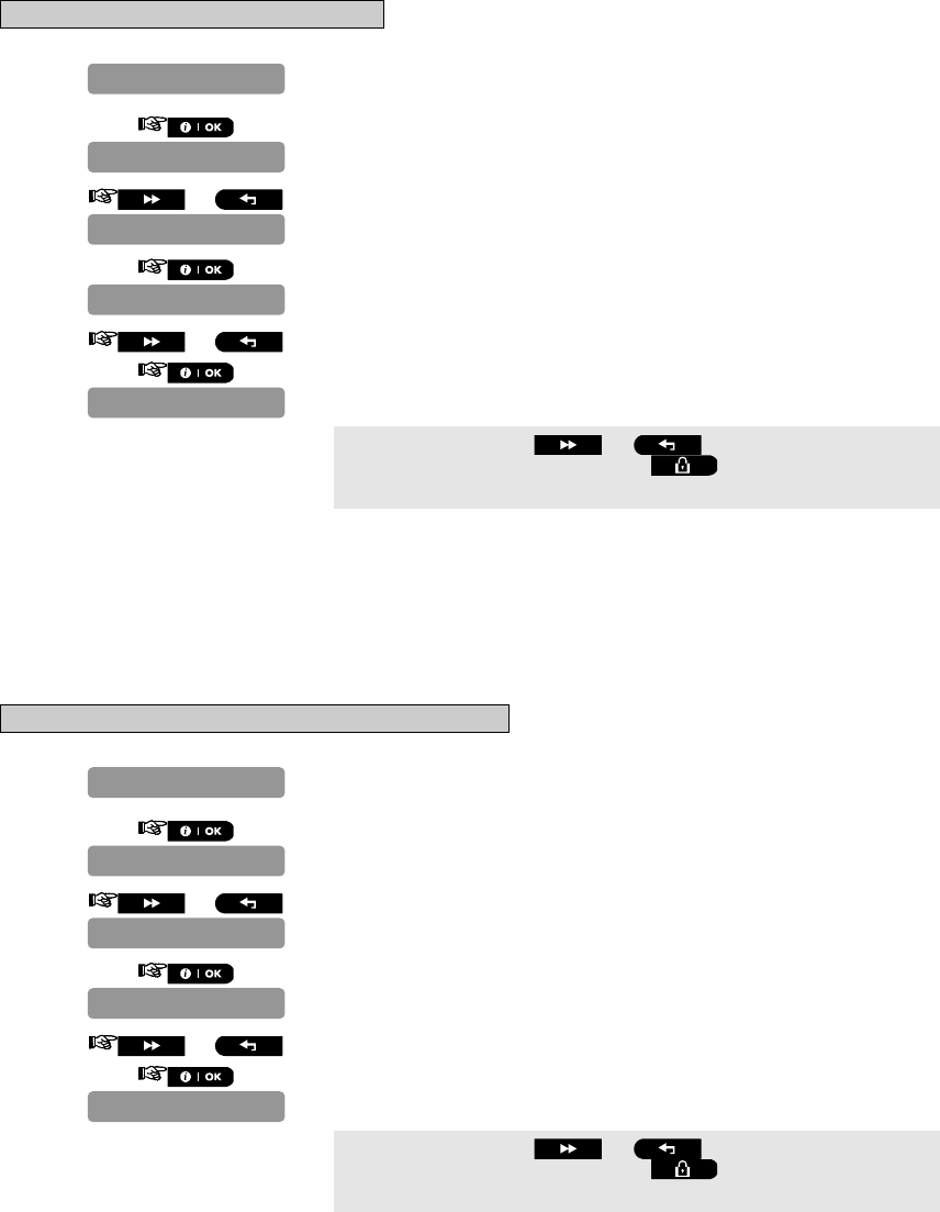
60 D-302756
4.10.6 Enabling the Memory Prompt
Here you determine whether the user will receive indication that an alarm has been activated.
Available options are: enable (default) and disable.
To Enable the Memory Prompt
1. Repeat steps 1 to 4 of section 4.2 "Entering the Installer Menu".
2.
3. or
4.
5. or Select between "enable" and "disable".
6.
You can now press the or button to program any other
menu in "DEFINE PANEL" or press the button to take you to "<OK>
TO EXIT".
4.10.7 Enabling Keyfob Low Battery Acknowledgement
Here you determine whether the user will hear or will not hear low battery sound when he tries to disarm the
system with a keyfob whose battery voltage is low.
Available options are: keyfob L-B on - the user has to acknowledge the keyfob low battery message, or, keyfob
L-B off (default) - the user does not have to acknowledge the keyfob low battery message.
To Enable Keyfob Low Battery Acknowledgement
1. Repeat steps 1 to 4 of section 4.2 "Entering the Installer Menu".
2.
3. or
4.
5. or Select between "keyfob L-B on" and "keyfob L-B off".
6.
You can now press the or button to program any other
menu in "DEFINE PANEL" or press the button to take you to "<OK>
TO EXIT".
31:LOW-BAT ACK
keyfob L-B off
31:LOW-BAT ACK
01:ENTRY DELAY 1
DEFINE PANEL
28:MEMORY PROMPT
enable
28:MEMORY PROMPT
01:ENTRY DELAY 1
DEFINE PANEL
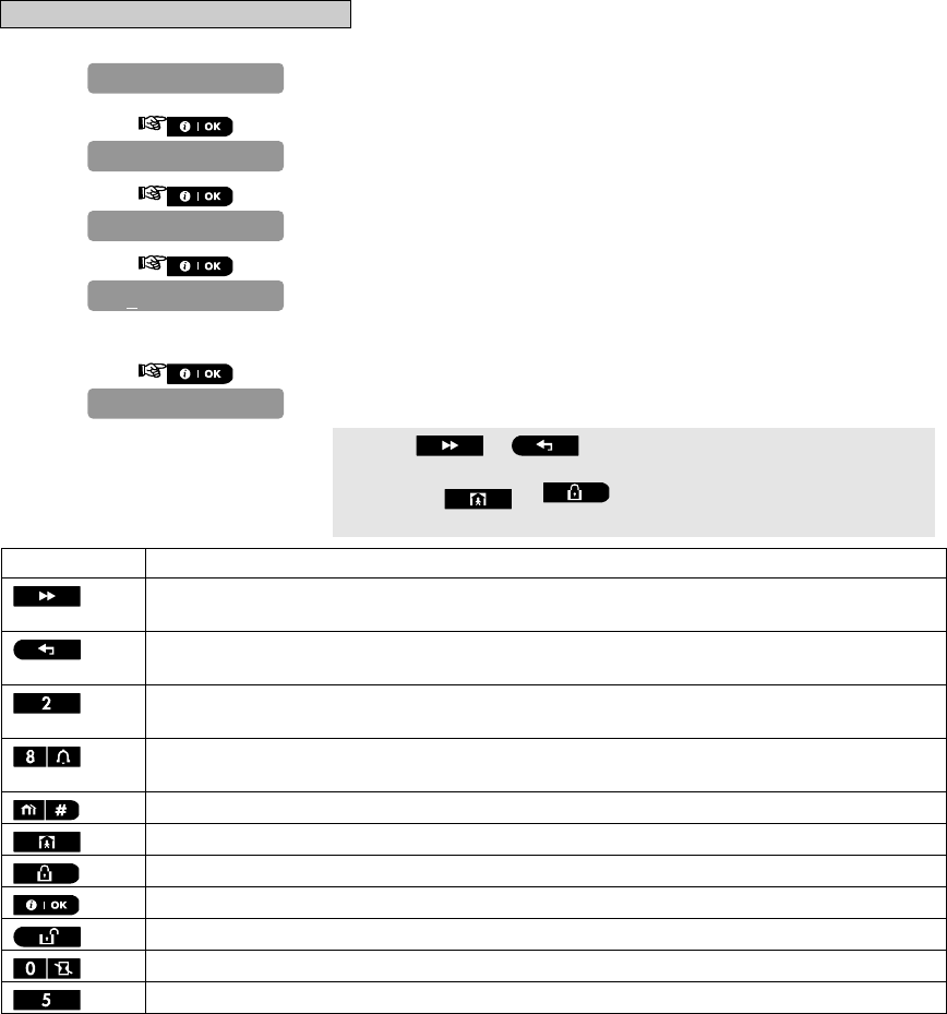
D-302756 61
4.11 DEFINE CUSTOM LOCATIONS
This mode allows you to define up to 5 locations (in addition to the locations that can be defined in the ZONES /
DEVICES mode - see par. 4.4).
To Define Custom Locations
1. Repeat steps 1 to 4 of section 4.2 "Entering the Installer Menu".
2.
3.
4.
Enter the first custom location.
Note: The table at the end of this section provides a list of the keys used
by the PowerMaster-10 editor.
5.
Press the or button and repeat the procedure for "EDIT
USER TERM 2" - –EDIT USER TERM 5", as required.
Pressing the or buttons at any stage in the procedure
will take you to “<OK> TO EXIT”.
Key Functionality
Moves the cursor from left to right.
Long press for speed.
Moves the cursor from right to left.
Long press for speed.
Scrolls upward the sequence of inserted digits.
Long press for speed.
Scrolls downward the sequence of inserted digits.
Long press for speed.
Places cursor to extreme right position of edit string and shows the last 16 digits of edit string.
Reverts to previous or top menu without saving the edit string.
Reverts to "<OK> TO EXIT" without saving the edit string.
Saves and reverts to previous menu.
Clears all digits to the right of cursor.
Clears one digit by cursor.
Selects between uppercase or lowercase digits.
4.12 CONFIGURING OUTPUT PARAMETERS
4.12.1 Preliminary Guidance
This mode allows you:
a. Events/conditions selection under which PGM (programmable) output will function.
b. Selection of the internal siren or STROBE light (that will be activated according to system programming).
EDIT USER TERM 1
Custom 1
EDIT USER TERM 1
CUST. ZONES NAME
DEFINE CUSTOM
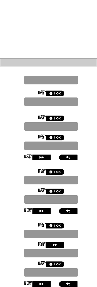
62 D-302756
4.12.2 Define PGM
For the PGM output, you can select disable, turn on, turn off or pulse active (turn on for predefined period,
selected by PULSE TIME), as follows:
ARM AWAY (upon AWAY arming).
ARM HOME (upon HOME arming).
DISARM (upon disarming).
MEMORY (activated upon registration of an alarm in the memory, turned off upon memory clearing).
DELAY (during exit / entry delays).
KEYFOB (upon AUX button pressing in the keyfob transmitter).
ZONES (by disturbance in each of 3 selected zones, irrespective of arming / disarming). If you select toggle,
the PGM output will be turned on upon event occurrence in these zones and will be turned off upon next
event occurrence, alternately.
LINE FAIL: PGM output is ON if telephone line is disconnected.
For PGM devices, you can select the following actions:
FLASH ON ALARM - you can select no flash or all light flash, to control PGM lighting devices in alarm
conditions.
LOCKOUT TIME - you can enter daytime limits between which PGM lighting devices controlled by sensors will
be off, even when the associated sensors are triggered.
A. To Configure Output Parameters
1. Repeat steps 1 to 4 of section 4.2 "Entering the Installer Menu".
2.
There are two sub-menus "DEFINE PGM" and "PGM GENERAL DEF".
The PowerMaster-10 display will first read "DEFINE PGM".
3.
4.
5. or Select between "pulse time 2s", "pulse time 30s", "pulse time
2m" and "pulse time 4m"
6.
7.
8. or Select between "disable", "turn ON", "turn OFF" and "
p
ulse
active".
9.
10.
11.
12. or Select between "disable", "turn ON", "turn OFF" and "
p
ulse
active".
disable
PGM: BY ARM HOME
PGM: BY ARM AWAY
disable
PGM: BY ARM AWAY
pulse time 2s
PGM: PULSE TIME
DEFINE PGM
DEFINE OUTPUTS

D-302756 63
13.
14.
15.
16. or Select between "disable", "turn ON", "turn OFF" and "pulse
active".
17.
18.
19.
20. or Select between "disable", "turn ON", "turn OFF" and "pulse
active".
21.
22.
23.
24. or Select between "disable", "turn ON", "turn OFF" and "pulse
active".
25.
26.
27.
28. or Select between "disable", "turn ON", "turn OFF", "pulse active"
and "toggle".
29.
30.
31.
32.
Enter the number of the first zone that you designate for activating this
output
a – zone Z:00
a - zone
PGM: BY KEYFOB
PGM: BY ZONES
disable
PGM: BY DELAY
PGM: BY KEYFOB
disable
PGM: BY MEMORY
PGM: BY DELAY
disable
PGM: BY DISARM
PGM: BY MEMORY
disable
PGM: BY DISARM
PGM: BY ARM HOME

64 D-302756
output.
33.
34. or Select between "disable", "turn ON", "turn OFF", "pulse active"
and "toggle".
35.
36.
37.
Enter the number of the second zone that you designate for activating
this output.
38.
39. or Select between "disable", "turn ON", "turn OFF", "pulse active"
and "toggle".
40.
41.
42.
Enter the number of the third zone that you designate for activating this
output.
43.
44. or Select between "disable", "turn ON", "turn OFF", "pulse active"
and "toggle".
45.
46.
47.
48.
49. or Select between "by line fail NO" and "by line failYES".
50.
Pressing the or buttons at any stage in the procedure
will take you to “<OK> TO EXIT”.
PGM: BY LINE
by line fail NO
PGM: BY LINE
PGM: BY ZONES
c - zone
c - zone
disable
c – zone Z:00
b - zone
b - zone
a - zone
disable
b – zone Z:00
disable
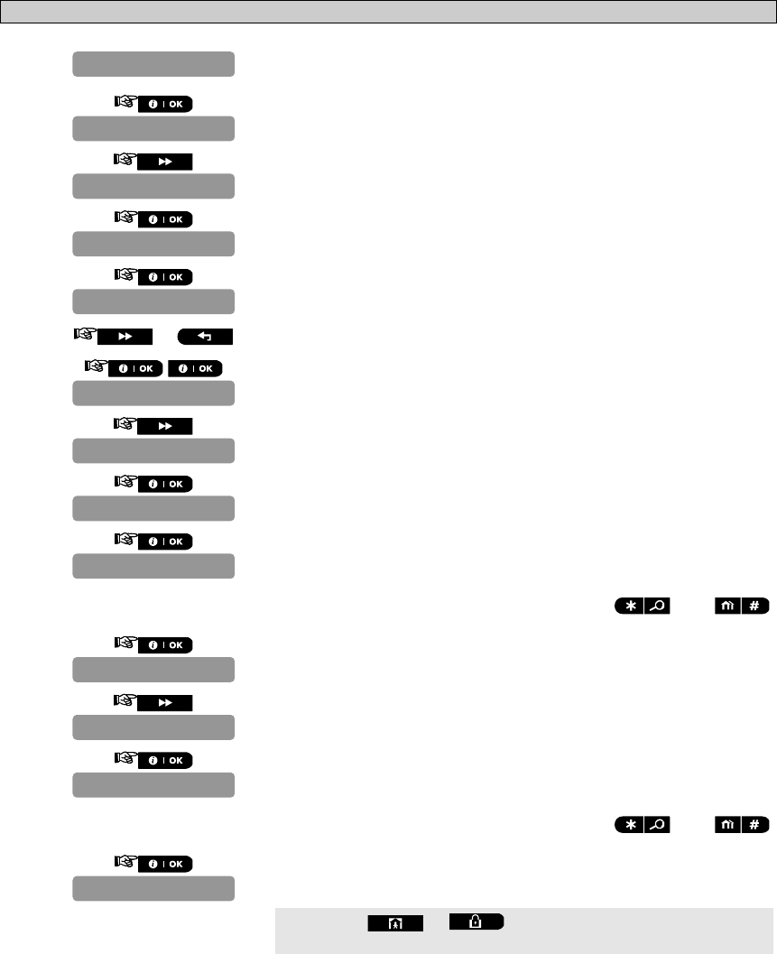
D-302756 65
B. To Configure PGM Lighting Devices in Alarm Conditions and To Set Daytime Limits of Lighting Devices
1. Repeat steps 1 to 4 of section 4.2 "Entering the Installer Menu".
2.
3.
4.
5.
6. or Select between "no flash" and "all light flash".
7.
8.
9.
10.
Enter the time at which you wish the lockout state to begin (usually at
dawn).
Note: AM and PM are selected by pressing and ,
respectively.
11.
12.
13.
Enter the time at which you wish the lockout state to end (usually in the
evening).
Note: AM and PM are selected by pressing and ,
respectively.
14.
Pressing the or buttons at any stage in the procedure
will take you to “<OK> TO EXIT”.
stop – HH:MM
TIME 07:00P
stop – HH:MM
start – HH:MM
FLASH ON ALARM
FLASH ON ALARM
TIME 07:00A
start – HH:MM
LOCKOUT TIME
no flash
PGM: GENERAL DEF
DEFINE PGM
DEFINE OUTPUTS

66 D-302756
4.13 Configuring Remote Programming Access Permissions
1. Repeat steps 1 to 4 of section 4.2 "Entering the Installer Menu".
2.
3.
4.
5. or
6.
Here you give or deny permission to access the system and exercise
control from a remote telephone.
7.
8. or Select between "rem. access ON" and "rem. access OFF"
9.
10.
Here you set the master installer 4-digit password for downloading/
uploading data to/from the PowerMaster-10 memory.
11.
Enter the 4-digit master download code ("0000" is not a valid code).
12.
13.
Here you set the installer 4-digit password for downloading data into the
PowerMaster-10 memory.
Attention! If "0000" is used, it will not enable connection of the
PowerMaster-10 to the PC for upload/download purpose.
14.
Enter the 4-digit installer download code ("0000" is not a valid code).
15.
16.
Here you determine whether the PowerMaster-10 data can be uploaded
into a computer while the system is in disarm state or at any time (in
HOME/AWAY arming & disarm state).
Inst. Downl code
Mast. Downl code
Remote access
REPORT EVENTS
Upload option
Remote access
rem. access ON
downl.code BBBB
Inst. Downl code
downl.code AAAA
Mast. downl code
PSTN UP / DOWN
3:C.S. REPORTING
1:PSTN/GSM
DEFINE COMM.

D-302756 67
17.
18. or Select between "any time" and "when system OFF".
19.
20.
Here you enter the telephone number (up to 16 digits) of the UL/DL server.
Note: Only for use of control panels monitored by compatible Monitoring
Stations. Leave empty if not used.
21.
Enter the upload/download software telephone number.
22.
23.
24.
25.
Here you enter the PowerMaster-10 SIM card telephone number. The
Monitoring Station dials this number when it needs to connect to the
PowerMaster-10 for uploading / downloading data.
26.
Enter the SIM card telephone number.
27.
28.
Here you determine the 1st IPMP receiver telephone number. When the
PowerMaster-10 responds to an incoming call from the telephone number
defined here, it creates a connection to the IPMP for uploading /
downloading data.
Note: Caller ID#1 / ID#2 should be 6 or more digits for wake-up by IPMP
to work.
29.
Enter the first IP receiver telephone number.
30.
31.
Here you determine the 2nd IPMP receiver telephone number. When the
PowerMaster-10 responds to an incoming call from the telephone
number defined here, it creates a connection to the IPMP for uploading /
downloading data.
32
1st caller ID#
2nd caller ID#
My SIM Tel.#
My SIM Tel.#
PSTN UP / DOWN
Up/Download tel#
Upload option
any time
1st caller ID#
Up/Download tel#
GPRS UP / DOWN

68 D-302756
Enter the second IP receiver telephone number.
33.
34.
You can now press the button to take you to the "RPRT CNFRM
ALARM" menu (see section 4.7.3.8), or press the button to take
you to "<OK> TO EXIT".
5 DIAGNOSTIC TEST
This mode allows you to test the functionality of all devices of the system and to receive / review information
regarding the received signal strength. Communication between system components can also be tested and
detailed information is reported.
The wireless signal strength measured and reported (see details in the drawing below).
IMPORTANT! Reliable reception must be assured during the initial testing and also throughout subsequent
system maintenance. A device should not be installed in location where signal strength is "poor". If you
get a "poor" signal strength from a certain device, simply re-locate it and re-test until a "good" or "strong" signal
strength is received. This principle should be followed throughout the diagnostic test procedure.
The diagnostic test process is shown below.
5.1 Testing Devices
This section describes how to test or review a device enrolled to the PowerMaster-10 control panel.
Note:
It is much easier to test the device while holding the device in your hand, close to the control panel.
5.1.1 Testing all Devices
1. Repeat steps 1 to 4 of section 4.2 "Entering the Installer Menu".
2.
3.
4. (or press the button for "TEST ONE DEVICE".)
or
The PowerMaster-10 system will now perform automatic testing of all
enrolled devices in the following order: repeaters, sirens, detectors,
keypads.
The PowerMaster-10 system will perform automatic testing of keyfobs (if
enrolled) at the end of testing all other devices.
ACTIVATE NOW Uxx
TEST KEYFOBS NN
TESTING Zxx NNN
TEST ALL DEVICES
WL DEVICES
DIAGNOSTICS
2nd caller ID#
GPRS UP / DOWN
D-302756 69
Note: "Zxx" indicates the type of device and device number that is being
tested. "NNN" indicates the number of devices that have not yet been
tested.
At this stage if any key is pressed the PowerMaster-10 display will read
"<NEXT> TO END" alternating with "<OK> TO CONTINUE". Press the
button to stop the current test and jump to the next test, or,
press the button to continue the test, or, press the
button to exit.
At the end of the testing procedure the PowerMaster-10 display will read
"SHOW ALL DEVICES".
If there are no wireless devices enrolled in the PowerMaster-10
system, the PowerMaster-10 display reads "NO DEVICES".
Pressing the or buttons at any stage in the procedure
will take you to "<NEXT> TO END" or “<OK> TO EXIT”.
5.1.2 Testing One Device
1. Repeat steps 1 to 4 of section 4.2 "Entering the Installer Menu".
2.
3.
4.
5.
6. or Select between "CONTACT SENSORS", "MOTION SENSORS", "SMOKE
SENSORS", "KEYFOBS", "SIRENS" or "REPEATERS", for example, "MOTION
SENSORS".
7.
The PowerMaster-10 display will read the device name alternating with
the location.
or (press the or button to select another enrolled device.)
8. The PowerMaster-10 display will read "TESTING Zxx 001" or
"ACTIVATE NOW Uxx" for keyfobs.
or
ACTIVATE NOW Uxx
Front door
Zxx:Motion Sens
MOTION SENSORS
CONTACT SENSORS
TEST ONE DEVICE
Z01 NOW: STRONG
TESTING Zxx 001
TEST ALL DEVICES
WL DEVICES
DIAGNOSTICS
70 D-302756
After testing the PowerMaster-10 display will then automatically change
to read the average level for the last 24 hours (for stationary devices) or
the number of activations that the control panel has received (for
keyfobs).
The signal strength indications are as follows: "STRONG"; GOOD"; "POOR";
"1-WAY" (the device operates in 1-way mode, or, the "NOW"
communication test failed); "NO COM." (no communication); "NOT TST"
(results are shown without any performed test); "NOT NET" (device is
pre-enrolled – not networked); "NONE" (keyfob 24Hr result); or "EARLY"
(result of the last 24Hrs without statistics).
Pressing the or buttons at any stage in the procedure
will take you to “<OK> TO EXIT”.
5.1.3 Displaying Signal Strength Indication of All Devices
1. Repeat steps 1 to 4 of section 4.2 "Entering the Installer Menu".
2.
3.
4. or
5.
The PowerMaster-10 display switches between the average signal
strength indication for the last 24 hours and the current signal strength
indications of the first device type.
6. Press the button to view the signal strength indications for the
next device type.*
The signal strength indications are as follows: "STRONG"; GOOD"; "POOR";
"1-WAY" (the device operates in 1-way mode, or, the "NOW"
communication test failed); "NO COM." (no communication); "NOT TST"
(results are shown without any performed test); "NOT NET" (device is
pre-enrolled – not networked); "NONE" (keyfob 24Hr result); or "EARLY"
(result of the last 24Hrs without statistics).
Pressing the button will display the number and type of device
to which the signal strength indications refer.
Pressing the or buttons at any stage in the procedure
will take you to “<OK> TO EXIT”.
K01: NOW: NONE
Z01: NOW: NOT
K01: 24hr: NONE
Z01: 24hr: GOOD
SHOW ALL DEVICES
TEST ALL DEVICES
WL DEVICES
DIAGNOSTICS
Z01 24Hr: EARLY

D-302756 71
5.1.4 Displaying Signal Strength Indication of RF Devices
1. Repeat steps 1 to 4 of section 4.2 "Entering the Installer Menu".
2.
3.
4. or
5.
The PowerMaster-10 display switches between the average signal
strength indication for the last 24 hours and the current signal strength
indications of the first device type.
6. Press the button to view the signal strength indications for the
next RF device type.*
The signal strength indications are as follows: "STRONG"; GOOD"; "POOR";
"1-WAY" (the device operates in 1-way mode, or, the "NOW"
communication test failed); "NO COM." (no communication); "NOT TST"
(results are shown without any performed test); "NOT NET" (device is
pre-enrolled – not networked); "NONE" (keyfob 24Hr result); or "EARLY"
(result of the last 24Hrs without statistics).
Pressing the button will display the number and type of device
to which the signal strength indications refer.
Pressing the or buttons at any stage in the procedure
will take you to “<OK> TO EXIT”.
5.1.5 GPRS Communication Test
The GPRS Communication diagnostic procedure tests GSM/GPRS communication and reports the diagnostic
result. In case of communication failure, detailed information of the failure is reported.
1. Repeat steps 1 to 4 of section 4.2 "Entering the Installer Menu".
2.
*
3.
4. **
GSM/GPRS
WL DEVICES
DIAGNOSTICS
K01: NOW: NONE
Z01: NOW: NOT
K01: 24hr: NONE
Z01: 24hr: GOOD
SHOW RF PROBLEMS
TEST ALL DEVICES
WL DEVICES
DIAGNOSTICS
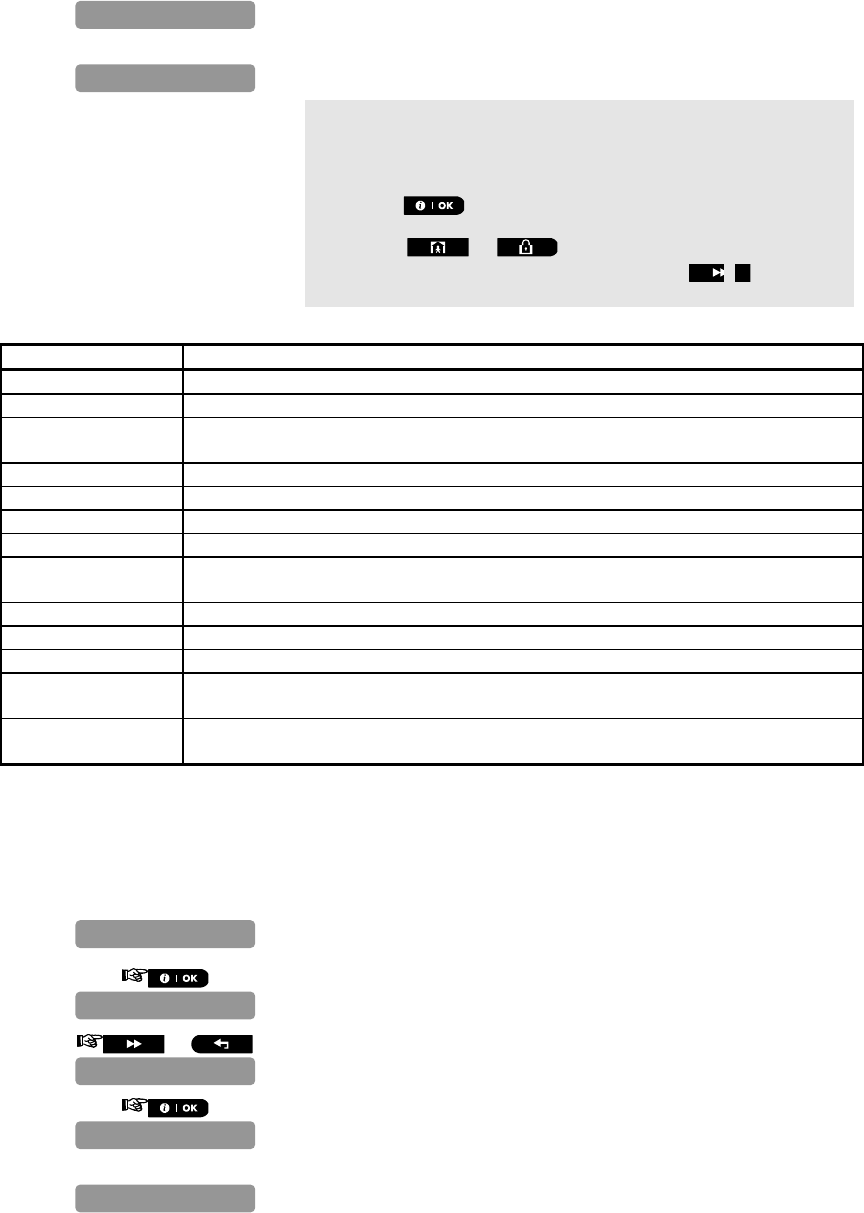
72 D-302756
See the table below for a complete list of possible GSM/GPRS
messages.
If there are no wireless devices enrolled in the PowerMaster-10
system, the PowerMaster-10 display reads "NO DEVICES".
** When the button is pressed the test result takes up to 4 min.
before it is displayed, depending on the severity of the failure.
Pressing the or buttons at any stage in the procedure
will take you to “<OK> TO EXIT” or pressing the button at the
end of the procedure will take you to the "LAN" menu.
The following GSM/ GPRS messages are reported:
Message Description
Unit is OK GSM / GPRS is functioning correctly.
GSM comm. loss The GSM/GPRS module does not communicate with the Panel
Pin code fail Missing or wrong PIN code.
(Only if SIM card PIN code is enabled.)
GSM net. fail Unit failed with registration to local GSM network.
SIM card fail SIM not installed or SIM card failure.
GSM not detected GSM auto enroll failed to detect GSM/GPRS module.
No GPRS service The SIM card does not have the GPRS service enabled.
GPRS conn. fail Local GPRS network is not available or, wrong setting to GPRS APN, user and/or
password.
Srvr unavailable IPMP Receiver cannot be reached – Check the Server IP
IP not defined Server IP #1 and #2 are not configured.
APN not defined APN is not configured.
SIM card locked After entering a wrong PIN code 3 consecutive times the SIM is locked. To unlock it
enter a PUK number. The PUK number cannot be entered by the PowerMaster-10.
Denied by server The IPMP denies the connection request. Check that the Panel is registered to the IPMP
Receiver.
5.1.6 LAN Connection Test
The LAN Connection diagnostic procedure tests PowerLink Broadband Module communication to the IPMP and
reports the diagnostic result. In case of communication failure, detailed information of the failure is reported.
Note: If the PowerLink Broadband Module is not registered to the PowerMaster-10, the menu "LAN
CONNECT.TEST" will not be displayed.
1. Repeat steps 1 to 4 of section 4.2 "Entering the Installer Menu".
2.
*
3. or
4. **
UNIT IS OK
PLEASE WAIT…
LAN
WL DEVICES
DIAGNOSTICS
UNIT IS OK
PLEASE WAIT…
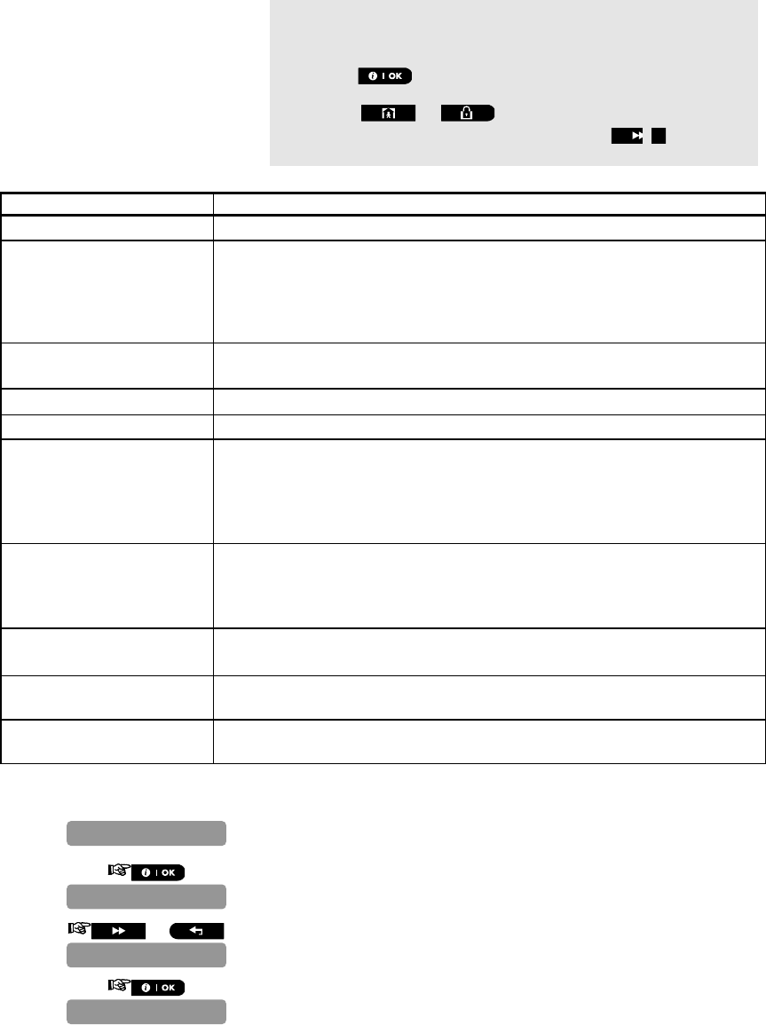
D-302756 73
See the table below for a complete list of possible LAN messages.
If there are no wireless devices enrolled in the PowerMaster-10
system, the PowerMaster-10 display reads "NO DEVICES".
** When the button is pressed the test result takes up to 4 min.
before it is displayed, depending on the severity of the failure.
Pressing the or buttons at any stage in the procedure
will take you to “<OK> TO EXIT” or pressing the button at the
end of the procedure will take you to the "LAN RESET OPTION" menu.
The following LAN messages are reported:
Message Description
Unit is ok PowerLink Broadband Module is functioning correctly.
Test aborted The diagnostic test is aborted, as follows:
AC failure – PowerLink Broadband Module is set to OFF mode.
PowerLink Broadband Module has not completed the power-up procedure. In
this case, the installer should wait a maximum of 30 seconds before re-
testing.
Comm. loss The RS-232 serial interface between the PowerLink Broadband Module and the
PowerMaster-10 failed.
Rcvr Ip missing Receivers IP 1 and 2 settings are missing in the PowerMaster-10.
Cable unplugged The Ethernet cable is not connected to the PowerLink Broadband Module.
Check lan config This message appears in any of the following cases:
Incorrect PowerLink Broadband Module IP has been entered.
Incorrect subnet mask has been entered.
Incorrect default gateway has been entered.
DHCP server failure.
Rcvr#1 UnReach.
Rcvr#2 UnReach.
Receiver 1 or 2 is inaccessible, as follows:
Wrong receiver IP has been entered.
Receiver failure.
WAN Network failure.
Rcvr#1 UnReg.
Rcvr#2 UnReg.
The PowerMaster-10 unit is not registered to IP receiver 1 or 2.
Broadband Module timeout
err.
PowerLink Broadband Module does not respond to test result within 70 sec.
Invalid result PowerLink Broadband Module responds with a result code that is not recognized
by the PowerMaster-10.
5.1.7 LAN Reset Option
1. Repeat steps 1 to 4 of section 4.2 "Entering the Installer Menu".
2.
*
3. or
4.
REBOOT
LAN RESET OPTION
WL DEVICES
DIAGNOSTICS
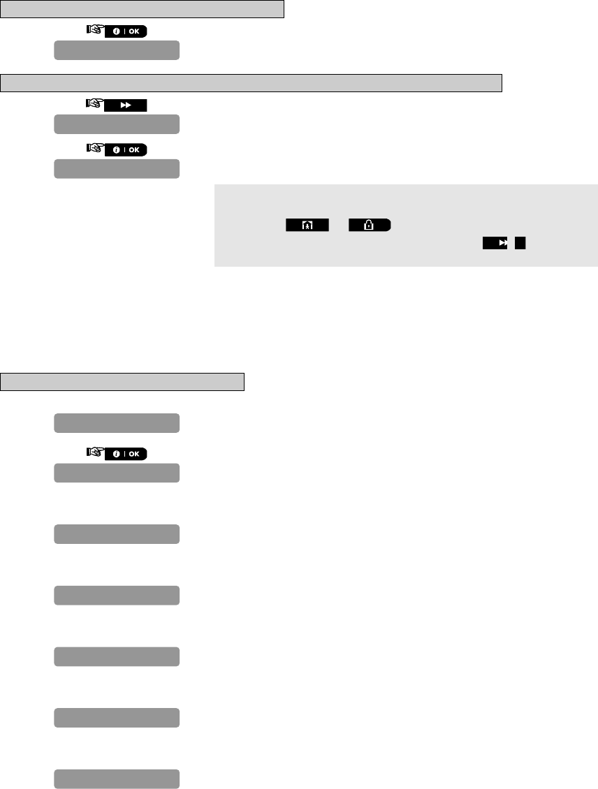
74 D-302756
To reset the PowerLink Broadband Module
5.
To reset all LAN setting definitions (does not reset Monitoring Station IP definitions)
6.
7.
If there are no wireless devices enrolled in the PowerMaster-10
system, the PowerMaster-10 display reads "NO DEVICES".
Pressing the or buttons at any stage in the procedure
will take you to “<OK> TO EXIT” or pressing the button at the
end of the procedure will take you to the "WL DEVICES" menu.
6 CALLING UPLOAD/DOWNLOAD SERVER
Note:
This option is only used during the installation of panels monitored by compatible Monitoring Stations.
This option allows the installer to initiate a call to the upload/download server. The server uploads the
PowerMaster-10 configuration to its data base and can unload predefined parameters to the PowerMaster-10.
To Perform Server Upload/Download
1. Repeat steps 1 to 4 of section 4.2 "Entering the Installer Menu".
2.
If the UL/DL server telephone number was already defined (see section
4.7.3.1 "Configuring the Types of Events to be Reported"), the
PowerMaster-10 display will read "COMMUNICATING" which is displayed
during the dialing process.
If the UL/DL server telephone number was not defined (see section
4.7.3.1 "Configuring the Types of Events to be Reported"), the
PowerMaster-10 display will read "TEL# NOT DEFINED" which is
displayed for approx. 30 sec. and is followed by a sad (failure) tune.
If communication has been established between the PowerMaster-10
control panel and the upload/download server, the PowerMaster-10
display will read "DOWNLOADING" which is displayed during the dialing
process.
If communication has failed between the PowerMaster-10 control panel
and the upload/download server, the PowerMaster-10 display will read
"DIAL ATTEMPT FAIL" which is displayed for approx. 30 sec. and is
followed by a sad (failure) tune.
After the downloaded/uploaded process has been completed
successfully, the PowerMaster-10 display will read "DOWNLOAD OK"
which is displayed for approx. 30 sec. and is followed by a happy
(success) tune.
If communication has been established between the PowerMaster-10
control panel and the upload/download server but the
downloaded/uploaded process has failed, the PowerMaster-10 display
will read "DOWNLOAD FAILED" which is displayed for approx. 30 sec.
and is followed by a sad (failure) tune.
DOWNLOAD FAILED
DOWNLOAD OK
DIAL ATTEMPT
DOWNLOADING
TEL# NOT DEFINED
COMMUNICATING
START UL/DL
FACTORY DEFIN.
FACTORY DEFIN.
REBOOT

D-302756 75
Pressing the or buttons at any stage in the procedure
will take you to “<OK> TO EXIT”.
7. MAINTENANCE
7.1 Handling System Troubles
Fault What it means Solution
1-WAY The control panel cannot configure or
control the device.
Battery consumption increases.
i) Make sure the device is physically
present.
ii) Check the display for device faults, for
example, low battery.
iii) Use RF diagnostics to check the current
signal strength and during the last 24
hours.
iv) Open the device cover and replace the
battery or press the tamper switch.
v) Install the device in a different location.
vi) Replace the device.
NOT
NETWORKED A device was not installed or not installed
correctly, or, cannot establish
communication with the control panel after
installation.
i) Make sure the device is physically
present.
ii) Use RF diagnostics to check the current
signal strength and during the last 24
hours.
iii) Open the device cover and replace the
battery or press the tamper switch.
iv) Enroll the device again.
MISSING A device or detector has not reported for
some time to the control panel. i) Make sure the device is physically
present.
ii) Check the display for device faults, for
example, low battery.
iii) Use RF diagnostics to check the current
signal strength and during the last 24
hours.
iv) Replace the battery.
v) Replace the device.
JAMMING A radio-frequency signal which is blocking
communication channel of sensors and
control panel is detected.
Locate the source of interference by
switching off any wireless devices
(cordless telephones, wireless ear plugs,
etc.) in the house for 2 minutes then check
if trouble continues.
Use also RF diagnostics to check signal
strength.
LOW BATTERY The battery in a sensor, keyfob or wireless
commander is near the end of its useful life. i) For AC powered devices, check AC
power is available and connected to the
device.
ii) Replace the device battery.
CLEAN ME The fire detector must be cleaned Use a vacuum cleaner to clean the
detector air vents occasionally to keep
them free of dust.
GAS TROUBLE Gas detector failure Gas detector: Disconnect and then put
back the AC power supply connector
CO Gas detector: Replace the detector

76 D-302756
Fault What it means Solution
SIREN AC
FAILURE There is no power to the siren Make sure that the AC power supply is
connected properly
AC FAILURE There is no power to gas sensor Make sure that the AC power supply is
connected properly
GSM NET FAIL The GSM communicator is not able to
connect to the cellular network. i) Move the Panel and GSM unit to
another location.
ii) Enter and exit the installer menu
iii) Disconnect GSM unit and install it again
iv) Replace SIM card
v) Replace the GSM unit
RSSI LOW The GSM communicator has detected that
GSM network signal is weak Move the Panel and GSM unit to another
location.
AC SUPPLY
FAILURE There is no power and the system is working
on backup battery power Make sure that the AC power supply is
connected properly
COMM. FAILURE A message could not be sent to the
monitoring station or to a private telephone
(or a message was sent but was not
acknowledged)
i) Check telephone cable connection
ii) Check that correct telephone number
has been dialed.
iii) Dial Monitoring Station to check
whether or not events are received.
CPU LOW
BATTERY The backup battery within the control panel
is weak and must be replaced (see
Chapter 7 - Replacing Backup Battery).
i) Check for AC power is available in the
Panel.
ii) If trouble exists for more than 72 hours,
replace the battery pack
CPU TAMPER The control panel was physically tampered
with or its cover was opened, or it was
removed from wall.
The control panel is not closed properly.
Open the control panel and then close it.
FUSE TROUBLE The PGM fuse is burnt out or overloaded. Make sure that the connection load
conforms to that specified in the
Specifications.
LINE FAILURE There is a problem with the telephone line i) Lift the telephone receiver and make
sure a telephone line can be heard
ii) Check the telephone connection to the
control panel
7.2 Dismounting the Control Panel
A. Remove the screw that fastens the front unit to the back unit (see Figure 3.3).
B. Remove the 4 screws that fasten the back unit to the mounting surface (see Figure 3.3) and remove the
control panel.
7.3 Replacing the Backup Battery
Replacement and first-time insertion of battery pack is similar (see Figure 3.1).
With fresh battery pack, correct insertion and tightened battery compartment lid, the TROUBLE indicator should
extinguish. However, the “MEMORY” message will now blink in the display (caused by the “tamper” alarm you
triggered when opening the battery compartment lid). Clear it by arming the system and immediately disarming.
7.4 Fuse Replacement
The PowerMaster-10 has an internal fuse that has automatic reset. Therefore, there is no need to replace the
fuse.
When over current condition occurs, the fuse cuts off the circuit current. Upon fault current being removed for
several seconds, the fuse is automatically reset and allows current flow through the circuit again.
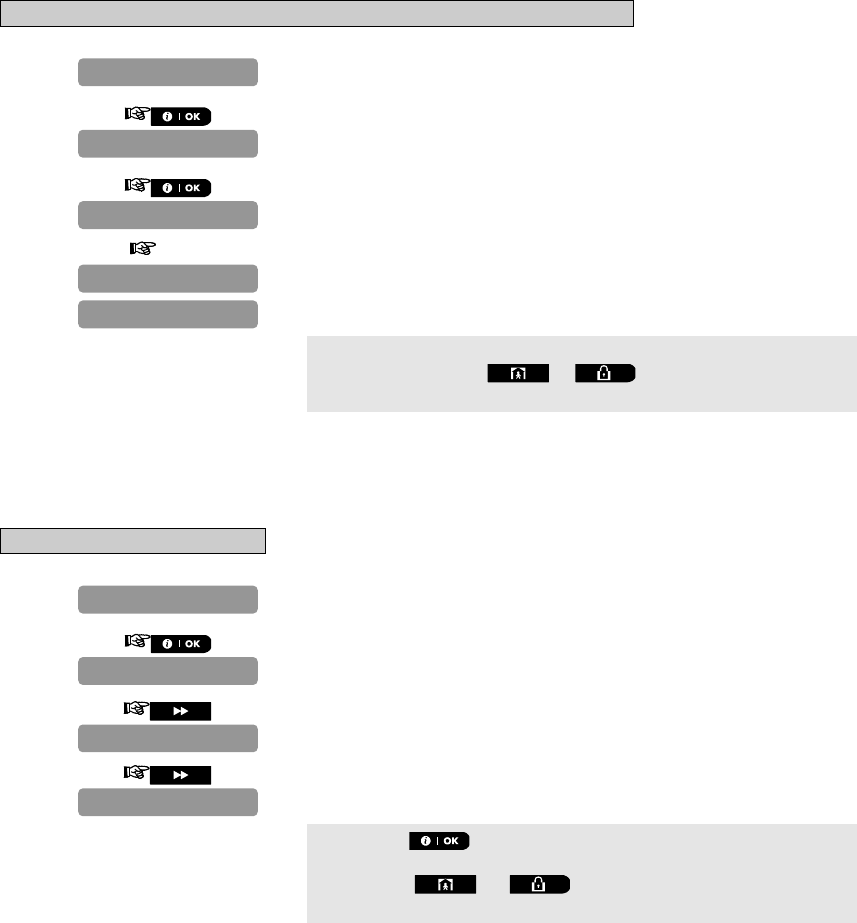
D-302756 77
7.5 Replacing/Relocating Detectors
Whenever maintenance work involves replacement or re-location of detectors, always perform a full diagnostic
test according to section 5.
Remember! A "poor" signal is not acceptable, as stated at the end of the introduction to the test procedure.
7.6 Restoring Factory Defaults
If you want to reset the PowerMaster-10 parameters to the factory default parameters, you should enter the
installer menu and perform the "FACTORY DEFLT" function, as detailed below. To get the relevant parameters
defaults, contact the PowerMaster-10 dealer.
Note: For PowerMaster-10 with 2 installer codes, INSTALLER code and MASTER INSTALLER code, only the
master installer code enables to perform factory default function.
To Reset PowerMaster-10 Parameters to the Factory Default Parameters
1. Repeat steps 1 to 4 of section 4.2 "Entering the Installer Menu".
2.
3.
The screen will now prompt you to enter your installer code.
4. CODE
The factory defaults are now restored.
You can now press the or buttons to take you to “<OK>
TO EXIT”.
7.7 Viewing the Serial Number
The menu "SERIAL NUMBER" allows reading the system serial number and panel ID for support purposes only.
Panel ID is a unique number of the control panel that is used for registering the PowerMaster-10 to IPMP when
using GPRS.
To View the Serial Number
1. Repeat steps 1 to 4 of section 4.2 "Entering the Installer Menu".
2.
The PowerMaster-10 display will read serial number of the unit.
3.
The PowerMaster-10 display will read the version of the unit.
4.
The PowerMaster-10 display will read the panel ID of the unit.
Pressing the button at any stage in the procedure will take you
to "SERIAL NUMBER".
Pressing the or buttons will take you to “<OK> TO
EXIT”.
FACTORY DEFLT
PLEASE WAIT…
ENTER CODE:
<OK> to restore
FACTORY DEFLT
Panel ID:
JSMivory 0.2.22
0907030000.
SERIAL NUMBER
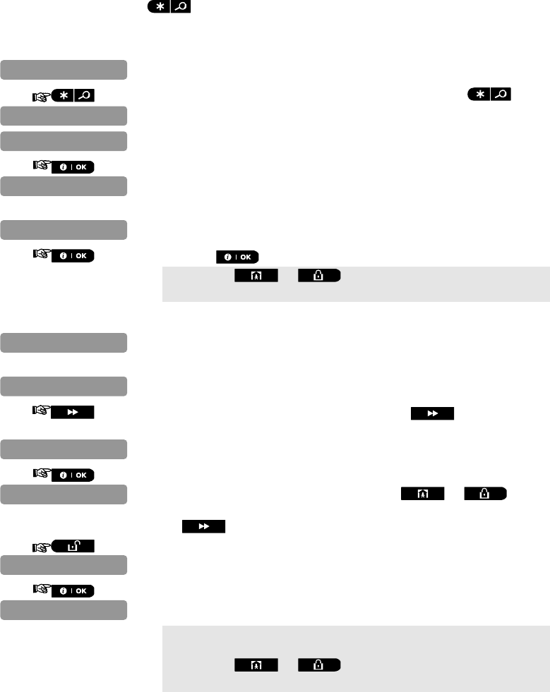
78 D-302756
8 READING THE EVENT LOG
Events are stored in the event log. You can access this log and review the events, one by one. If the event log
fills up completely, the oldest event is deleted upon registration of each new event.
The date and time of occurrence are memorized for each event.
When reading the event log, events are shown in chronological order - from the newest to the oldest. Access to the
event log is provided by pressing the button and not through the installer’s menu. The reading and erasing
process of the event log is shown below.
8.1 Reading the Event Log
1. While the system is in the normal operating mode, press the key.
2. Enter the current installer code.
3.
The latest event is shown.
The event is displayed in two parts, for example, "Z13 alarm" then
"09/02/10 3:37 P".
4. Press the button repeatedly to scroll through the list of events.
Pressing the or buttons at any stage in the procedure
will take you to “<OK> TO EXIT”.
8.2 Erasing and Exiting the Event Log
5. From anywhere within the event log, press the button.
Note: This is applicable only if the installer code entered.
6.
At this stage in the procedure, pressing the or buttons
will take you to “<OK> TO EXIT” without erasing the event log. Pressing
the button will return you to “CLEAR EVENT LOG”.
7.
8.
The system erases the event log and reverts to the normal operating
mode.
Pressing the or buttons at any stage in the procedure
will take you to “<OK> TO EXIT”.
READY 00:00
<OK> TO EXIT
<OFF> to delete
CLEAR EVENT LOG
09/02/10 3:37 P
Z13 alarm
09/02/10 3:37 P
Z13 alarm
LIST OF EVENTS
READY 00:00
ENTER CODE:

D-302756 79
APPENDIX A. Detector Deployment & Transmitter
Assignments
A1. Detector Deployment Plan
Zone
No. Zone Type Sensor Location or Transmitter Assignment
(in non-alarm or emergency zones) Chime
(Yes / No)
1
2
3
4
5
6
7
8
9
10
11
12
13
14
15
16
17
18
19
20
21
22
23
24
25
26
27
28
29 (*)
30 (*)
Zone Types: 1 = Interior follower
2 = Perimeter
3 = Perimeter follower
4 = Delay 1
5 = Delay 2
6 =
24 h silent
7 = 24 h audible
8 = Non-alarm
9 = Emergency
10 = Interior
11 = Home / delay.
Zone Locations: Note down the intended location for each detector. When programming, you may select one of
26 available locations (plus 5 custom locations that you can add – see Zones Devices menu).
* Zones 29 only is hardwired zones.

80 D-302756
A2. Keyfob Transmitter List
Transmitter Data AUX button Assignments
No. Type Holder Skip exit delay or Arming
“instant”
1
2
3
4
5
Indicate the desired function (if
any)
6 Skip exit delay
7 Arming “instant”
8
A3. Emergency Transmitter List
Tx # Transmitter Type Enrolled to Zone Name of holder
1
2
3
4
5
6
7
8
9
10
A4. Non-Alarm Transmitter List
Tx # Transmitter
Type Enrolled to Zone Name of holder Assignment
1
2
3
4
5
6
7
8
9
10

D-302756 81
APPENDIX B. Event Codes
B1. Contact ID Event Codes
Code Definition Code Definition
101 Emergency 351 Telco fault
110 Fire 373 Fire detector trouble
120 Panic 381 Loss of supervision RF
121 Duress 383 Sensor tamper
122 Silent 384 RF low battery
123 Audible 393 Fire detector clean me
131 Perimeter 401 O/C by user
132 Interior 403 Auto arm
134 Entry/Exit 406 Cancel
137 Tamper/CP 408 Quick arm
139 Burglary verified 426 Door open event
151 Gas alarm 441 Armed home
154 Flood alarm 454 Fail to close
180 Gas trouble 455 Fail to arm
301 AC loss 456 Partial arm
302 Low system battery 459 Recent close event
311 Battery disconnect 570 Bypass
313 Engineer reset 602 Periodic test report
321 Bell 607 Walk test mode
344 RF receiver jam detect 641 Senior watch trouble
350 Communication trouble
B2. SIA Event Codes
Code Definition Code Definition
AR AC Restore GJ Gas trouble restore
AT AC Trouble HA Holdup Alarm (duress)
BA Burglary Alarm LR Phone Line Restore
BB Burglary Bypass LT Phone Line Trouble
BC Burglary Cancel OP Opening Report
BR Burglary Restore OT Fail to Arm
BT Burglary Trouble / Jamming PA Panic Alarm
BV Burglary Verified QA Emergency Alarm
BZ Missing Supervision RN Engineer Reset
CF Forced Closing RP Automatic Test
CI Fail to Close RX Manual Test
CL Closing Report RY Exit from Manual Test
CP Auto Arm TA Tamper Alarm
CR Recent Close TR Tamper Restore
EA Door Open WA Flood alarm
FA Fire Alarm WR Flood alarm restore
FT Fire Detector Clean XR Sensor Battery Restore
FJ Fire detector trouble XT Sensor Battery Trouble
FR Fire Restore YR System Battery Restore
GA Gas alarm YT System Battery Trouble / Disconnection
GR Gas alarm restore YX Service Required
GT Gas trouble
B3. 4/2 Event Codes
Note: The report to Monitoring Station is on the following zones: First wireless siren - zone 31, second wireless siren -
zone 32, GSM - zone 33.

82 D-302756
Alarms
Zone # 1 2 3 4 5 6 7 8 9 10 11 12 13 14 15 16 17 18 19 20 21 22 23 24 25 26 27 28 29
1st digit 4 4 4 4 4 4 4 4 444444455555555 5 5 5 555
2nd
digit 1 2 3 4 5 6 7 8 9ABCDEF12345678 9 A B CDE
Restorals
Zone # 1 2 3 4 5 6 7 8 9 10 11 12 13 14 15 16 17 18 19 20 21 22 23 24 25 26 27 28 29
1st digit C C C C C C C C CCCCCCCDDDDDDDD D D D DDD
2nd
digit 1 2 3 4 5 6 7 8 9ABCDEF12345678 9 A B CDE
Supervisory trouble
Zone # 1 2 3 4 5 6 7 8 9 10 11 12 13 14 15 16 17 18 19 20 21 22 23 24 25 26 27 28
1st digit 6 6 6 6 6 6 6 6 6 6 6 6 6 6 6 7 7 7 7 7 7 7 7 7 7 7 7 7
2nd digit 1 2 3 4 5 6 7 8 9 A B C D E F 1 2 3 4 5 6 7 8 9 A B C D
Low Battery
Zone # 1 2 3 4 5 6 7 8 9 10 11 12 13 14 15 16 17 18 19 20 21 22 23 24 25 26 27 28
1st digit 8 8 8 8 8 8 8 8 8 8 8 8 8 8 8 9 9 9 9 9 9 9 9 9 9 9 9 9
2nd digit 1 2 3 4 5 6 7 8 9 A B C D E F 1 2 3 4 5 6 7 8 9 A B C D
Forced Arming – 8 users
User No. 1 2 3 4 5 6 7 8
1st digit A A A A A A A A
2nd digit 1 2 3 4 5 6 7 8
Zone Bypass
Zone # 1 2 3 4 5 6 7 8 9 10 11 12 13 14 15 16 17 18 19 20 21 22 23 24 25 26 27 28 29
1st digit A A A A A A A A AAAAAAABBBBBBBB B B B BBB
2nd
digit 1 2 3 4 5 6 7 8 9ABCDEF12345678 9 A B CDE
Panic / 24 Hours - 8 users
User No. 1 2 3 4 5 6 7 8 Panic CP Duress
1st digit 2 2 2 2 2 2 2 2 2 2
2nd digit 1 2 3 4 5 6 7 8 9 A
Arm HOME and AWAY (Closing)
User No. 1 2 3 4 5 6 7 8 Cancel alarm Recent Close
1st digit E E E E E E E E E E
2nd digit 1 2 3 4 5 6 7 8 9 C
Disarm (Opening)
User No. 1 2 3 4 5 6 7 8
1st digit F F F F F F F F
2nd digit 1 2 3 4 5 6 7 8
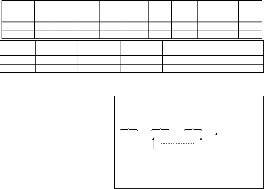
D-302756 83
Trouble
Event Fuse
Fail Fuse
Restore Jamming Jamming
Restore AC
Failure AC
Restore CPU
Low
Battery
CPU Low
Battery
Restore
CP
Tamper
1st digit 2 2 2 2 1 1 1 1 1
2nd digit C D E F 1 2 3 4 6
Event CP Tamper
Restore No Active COMM. &
LINE Restore Enter Test Exit Test Auto Test
1st digit 1 1 1 1 1 1
2nd digit 7 8 A D E F
B4. Understanding the Scancom Reporting Protocol Data Format
The SCANCOM data format consists of 13
decimal digits divided into 4 groups, from left to
right, as shown at the right side.
Each channel is associated with a specific
event as follows:
1st "C": Fire
2nd "C": Personal attack
3rd "C": Intruder
4th "C": Open/close
5th "C": Alarm cancel
6th "C": Emergency
7th "C": Second alarm
8th "C": Trouble messages
aaaa cccc cccc s
Account
Code Channels
1 - 4 Channels
5 - 8 System Status:
no trouble,
test, low battery
The digit in this position conveys
the status of channel 1 The digit in this position conveys
the status of channel 8
Scancom Data Format

84 D-302756
APPENDIX C. Glossary
This list of terms is arranged in alphabetical order.
Any term indicated by cursive (italic) letters within
the explanatory text can be looked up separately.
Abort Period: When an alarm is initiated, the
internal sounder is activated first for a limited period
of time which is the abort period set by the installer. If
you cause an alarm accidentally, you can disarm the
system within the abort period before the real sirens
start and before the alarm is reported to the remote
responders.
Alarm: There are 2 kinds of alarm:
Loud alarm - both internal and external sirens blare
out constantly and the control panel reports the event
by telephone.
Silent alarm - the sirens remain silent, but the control
panel reports the event by telephone.
A state of alarm is caused by:
Motion detected by a motion detector
Change of state detected by a magnetic contact
detector - a closed window or door is opened
Detection of smoke by a smoke detector
Tampering with any one of the detectors
Pressing the two emergency buttons
simultaneously (panic).
Arming: Arming the alarm system is an action that
prepares it to sound an alarm if a zone is “violated”
by motion or by opening a door or window, as the
case may be. The control panel may be armed in
various modes (see AWAY, HOME, INSTANT and
LATCHKEY).
Assigned: Refers to zones.
Associated: Refers to devices.
AWAY: This type of arming is used when the
protected site is vacated entirely. All zones, interior
and perimeter alike, are protected.
Chime Zones: Allow you to keep track of activity in
the protected area while the alarm system is in the
disarmed state. Whenever a chime zone is "opened",
the buzzer beeps twice. The buzzer doesn't beep,
however, upon closing the zone (return to normal).
Residences can use this feature to annunciate
visitors or look after children. Businesses can use it
to signal when customers enter the premises or
when personnel enter restricted areas.
Note: Your installer will never designate a 24-hour
zone or a fire zone as a chime zone, because both
zone types actuate an alarm if disturbed while the
system is in the disarmed state.
Although one zone or more are designated as chime
zones, you can still enable or disable the chime
function.
Communicators: Refers to communication channel,
for example, GSM, PSTN and broadband.
Control Panel: The control panel is a cabinet that
incorporates the electronic circuitry and
microprocessor that control the alarm system. It
collects information from various sensors, processes
it and responds in various ways. It also includes the
user-interface - control keys, numerical keypad,
display, sounder and loudspeaker.
Default Settings: Settings that are applicable to a
specific device group.
Detector: The device (apparatus) that sends an
alarm, that communicates with the control panel (e.g.
Tower 20 AM is a motion detector, MCT-425 is a
smoke detector)
Disarming: The opposite of arming - an action that
restores the control panel to the normal standby
state. In this state, only fire and 24-hour zones will
sound an alarm if violated, but a “panic alarm” may
also be initiated.
Disturbed Zone: A zone in a state of alarm (this
may be caused by an open window or door or by
motion in the field of view of a motion detector). A
disturbed zone is considered “not secured”.
Forced Arming: When any one of the system zones
is disturbed (open), the alarm system cannot be
armed. One way to solve this problem is to find and
eliminate the cause for zone disturbance (closing
doors and windows). Another way to deal with this is
to impose forced arming - automatic de-activation of
zones that are still disturbed upon termination of the
exit delay. Bypassed zones will not be protected
throughout the arming period. Even if restored to
normal (closed), bypassed zones will remain
unprotected until the system is disarmed.
Permission to “force arm” is given or denied by the
installer while programming the system.
HOME: This type of arming is used when people are
present within the protected site. A classic example
is night-time at home, when the family is about to
retire to bed. With HOME arming, perimeter zones
are protected but interior zones are not.
Consequently, motion within interior zones will be
ignored by the control panel, but disturbance of a
perimeter zone will cause an alarm.
Instant: You can arm the system AWAY-INSTANT
or HOME-INSTANT, thereby canceling the entry
delay for all delay zones for the duration of one
arming period.
For example, you may arm the control panel in the
HOME-INSTANT mode and remain within the
protected area. Only perimeter protection is active,
and if you do not expect somebody to drop in while
the system is armed, alarm upon entry via the main
door is an advantage.

D-302756 85
To disarm the system without causing an alarm, use
your control keypad (which is normally accessible
without disturbing a perimeter zone) or use a keyfob
transmitter.
Latchkey: The Latchkey mode is a special arming
mode in which designated "latchkey users" will
trigger a "latchkey message" to be sent to a
telephone or a pager when they disarm the system.
For example, if a parent wants to be sure that their
child has returned from school and disarmed the
system. Latchkey arming is only possible when the
system is armed in the AWAY mode.
Location: Assigning a named location to a device
(e.g. Garage, Front Door etc.)
Magnetic Contact Detector, Wireless: A Magnet-
controlled switch and a wireless PowerG transmitter in a
shared housing. The detector is mounted on doors and
windows to detect changes in state (from closed to
open and vice versa). Upon sensing that a door or
window is open, the detector transmits its unique
identification code accompanied by an “alarm” signal
and various other status signals to the control panel.
The control panel, if not armed at that time, will consider
the alarm system as “not ready for arming” until it
receives a “restored” signal from the same detector.
Motion Detector, Wireless: A passive Infrared
motion sensor and a wireless PowerG transmitter in a
shared housing. Upon sensing motion, the detector
transmits its unique identification code, accompanied
by an alarm signal and various other status signals to
the control panel. After transmission, it stands by to
sense further motion.
Non-Alarm Zone: Your installer can designate a
zone for roles other than alarm. For instance, a
motion detector installed in a dark stairway may be
used to switch on lights automatically when someone
crosses the dark area. Another example is a
miniature wireless transmitter linked to a zone that
controls a gate opening mechanism.
Quick Arming: Arming without a user code. The
control panel does not request your user code when
you press one of the arming buttons. Permission to
use this arming method is given or denied by the
installer while programming the system.
Remote Responder: A responder can be either a
professional service provider to which the home or
business owner subscribes (a Monitoring Station) or a
family relation/friend who agrees to look after the
protected site during absence of its occupants. The
control panel reports events by telephone to both
kinds of responders.
Restore: When a detector reverts from the state of
alarm to the normal standby state, it is said to have
been “restored”.
A motion detector restores automatically after
detection of movement, and becomes ready to detect
again. This kind of “restore” is not reported to the
remote responders.
A magnetic contact detector restores only upon
closure of the protected door or window. This kind of
“restore” is reported to the remote responders.
Sensor: The sensing element: pyroelectric sensor,
photo-diode, microphone, smoke optical sensor etc.
Signal Strength: The quality link communication
between the system components and the control
panel.
Smoke Detector, Wireless: A regular smoke detector
and a wireless PowerG transmitter in a shared housing.
Upon detection of smoke, the detector transmits its
unique identification code accompanied by an alarm
signal and various status signals to the control panel.
Since the smoke detector is linked to a special fire zone,
a fire alarm is initiated.
State: AWAY, HOME, AWAY-INSTANT, HOME-
INSTANT, LATCHKEY, FORCED, BYPASS.
Status: AC fail, low battery, trouble, etc
User Codes: The PowerMaster-10 is designed to
obey your commands, provided that they are
preceded by a valid security access code.
Unauthorized people do not know this code, so any
attempt on their part to disarm or defeat the system
is bound to fail. Some operations, however, can be
carried out without a user code as they do not
degrade the security level of the alarm system.
Zone: A zone is an area within the protected site
under supervision of a specific detector. During
programming, the installer allows the control panel to
learn the detector’s identity code and links it to the
desired zone. Since the zone is distinguished by
number and name, the control panel can report the
zone status to the user and register in its memory all
the events reported by the zone detector. Instant and
delay zones are “on watch” only when the control
panel is armed, and other (24-hour) zones are “on
watch” regardless of whether the system is armed or
not.
Zone Type: The zone type determines how the
system handles alarms and other signals sent from
the device
.

86 D-302756
APPENDIX D. DEFAULT AND PROGRAMMED ZONE
DEFINITIONS
Zone Zone Type Location Chime (melody
No. Default Programmed Default Programmed Location or Off) (*)
1 Delay 1 Front Door
2 Delay 1 Garage
3 Delay 2 Garage Door
4 Perimeter Back Door
5 Perimeter Child Room
6 Interior Office
7 Interior Dining Room
8 Perimeter Dining Room
9 Perimeter Kitchen
10 Perimeter Living Room
11 Interior Living Room
12 Interior Bedroom
13 Perimeter Bedroom
14 Perimeter Guest Room
15 Interior Master Bedroom
16 Perimeter Master Bedroom
17 Perimeter Laundry Room
18 Perimeter Master Bathroom
19 Perimeter Basement
20 24 h /
audible Fire
21 24 h /
audible Fire
22 Emergency Emergency
23 Emergency Emergency
24 24 h / silent Basement
25 24 h / silent Office
26 24 h /
audible Attic
27 24 h /
audible Den
28 non-alarm Yard
29 non-alarm Hall
30 non-alarm Utility room
* Note: All zones are CHIME OFF by default. Enter your own choice in the last column and program
accordingly.

D-302756 87
Industry Canada Declaration
This product meets the applicable Industry Canada technical specifications/Le présent materiel est conforme aux specifications
techniques appliables d’Industrie Canada.
The Ringer Equivalence Number is an indication of the maximum number of devices allowed to be connected to a telephone
interface. The termination on an interface may consist of any combination of devices subject only to the requirement that the
sum of the RENs of all the devices does not exceed five/L’indice d’équivalence de la sonnerie (IES) sert à indiquer le nombre
maximal de terminaux qui peuvent être raccordés à une interface téléphonique. La terminaison d’une interface peut consister
en une combinaison quelconque de dispositifs, à la seule condition que la somme d’indices d’équivalence de la sonnerie de
tous les dispositifs n’excède pas 5.
The Ringer Equivalence Number (REN) for this terminal equipment is 0.3B.
This device complies with FCC Rules Part 15. Operation is subject to two conditions: (1) This device may not cause harmful
interference, and (2) this device must accept any interference that may be received or that may cause undesired operation.
This device has been tested and found to comply with the limits for a Class B digital device, pursuant to Part 15 of the
FCC Rules. These limits are designed to provide reasonable protection against harmful interference in residential
installations. This equipment generates uses and can radiate radio frequency energy and, if not installed and used in
accordance with the instructions, may cause harmful interference to radio and television reception.
However, there is no guarantee that interference will not occur in a particular installation. If this device does cause such
interference, which can be verified by turning the device off and on, the user is encouraged to eliminate the interference by one or
more of the following measures:
– Re-orient or re-locate the receiving antenna.
– Increase the distance between the device and the receiver.
– Connect the device to an outlet on a circuit different from the one that supplies power to the receiver.
– Consult the dealer or an experienced radio/TV technician.
WARNING! Changes or modifications to this unit not expressly approved by the party responsible for compliance could void the
user’s authority to operate the equipment.

88 D-302756
WARRANTY
Visonic Limited (the “Manufacturer") warrants this product only (the "Product") to the original
purchaser only (the “Purchaser”) against defective workmanship and materials under normal
use of the Product for a period of twelve (12) months from the date of shipment by the
Manufacturer.
This Warranty is absolutely conditional upon the Product having been properly installed,
maintained and operated under conditions of normal use in accordance with the
Manufacturers recommended installation and operation instructions. Products which have
become defective for any other reason, according to the Manufacturers discretion, such as
improper installation, failure to follow recommended installation and operational instructions,
neglect, willful damage, misuse or vandalism, accidental damage, alteration or tampering, or
repair by anyone other than the manufacturer, are not covered by this Warranty.
The Manufacturer does not represent that this Product may not be compromised and/or
circumvented or that the Product will prevent any death and/or personal injury and/or damage
to property resulting from burglary, robbery, fire or otherwise, or that the Product will in all
cases provide adequate warning or protection. The Product, properly installed and
maintained, only reduces the risk of such events without warning and it is not a guarantee or
insurance that such events will not occur.
THIS WARRANTY IS EXCLUSIVE AND EXPRESSLY IN LIEU OF ALL OTHER
WARRANTIES, OBLIGATIONS OR LIABILITIES, WHETHER WRITTEN, ORAL, EXPRESS
OR IMPLIED, INCLUDING ANY WARRANTY OF MERCHANTABILITY OR FITNESS FOR A
PARTICULAR PURPOSE, OR OTHERWISE. IN NO CASE SHALL THE MANUFACTURER
BE LIABLE TO ANYONE FOR ANY CONSEQUENTIAL OR INCIDENTAL DAMAGES FOR
BREACH OF THIS WARRANTY OR ANY OTHER WARRANTIES WHATSOEVER, AS
AFORESAID.
THE MANUFACTURER SHALL IN NO EVENT BE LIABLE FOR ANY SPECIAL, INDIRECT,
INCIDENTAL, CONSEQUENTIAL OR PUNITIVE DAMAGES OR FOR LOSS, DAMAGE, OR
EXPENSE, INCLUDING LOSS OF USE, PROFITS, REVENUE, OR GOODWILL, DIRECTLY
OR INDIRECTLY ARISING FROM PURCHASER’S USE OR INABILITY TO USE THE
PRODUCT, OR FOR LOSS OR DESTRUCTION OF OTHER PROPERTY OR FROM ANY
OTHER CAUSE, EVEN IF MANUFACTURER HAS BEEN ADVISED OF THE POSSIBILITY
OF SUCH DAMAGE.
THE MANUFACTURER SHALL HAVE NO LIABILITY FOR ANY DEATH, PERSONAL
AND/OR BODILY INJURY AND/OR DAMAGE TO PROPERTY OR OTHER LOSS
WHETHER DIRECT, INDIRECT, INCIDENTAL, CONSEQUENTIAL OR OTHERWISE,
BASED ON A CLAIM THAT THE PRODUCT FAILED TO FUNCTION.
However, if the Manufacturer is held liable, whether directly or indirectly, for any loss or
damage arising under this limited warranty, THE MANUFACTURER'S MAXIMUM
LIABILITY (IF ANY) SHALL NOT IN ANY CASE EXCEED THE PURCHASE PRICE OF
THE PRODUCT, which shall be fixed as liquidated damages and not as a penalty, and shall
be the complete and exclusive remedy against the Manufacturer.
When accepting the delivery of the Product, the Purchaser agrees to the said conditions of
sale and warranty and he recognizes having been informed of.
Some jurisdictions do not allow the exclusion or limitation of incidental or consequential
damages, so these limitations may not apply under certain circumstances.
The Manufacturer shall be under no liability whatsoever arising out of the corruption and/or
malfunctioning of any telecommunication or electronic equipment or any programs.
The Manufacturers obligations under this Warranty are limited solely to repair and/or replace
at the Manufacturer’s discretion any Product or part thereof that may prove defective. Any
repair and/or replacement shall not extend the original Warranty period. The Manufacturer
shall not be responsible for dismantling and/or reinstallation costs. To exercise this
Warranty the Product must be returned to the Manufacturer freight pre-paid and insured. All
freight and insurance costs are the responsibility of the Purchaser and are not included in
this Warranty.
This warranty shall not be modified, varied or extended, and the Manufacturer does not
authorize any person to act on its behalf in the modification, variation or extension of this
warranty. This warranty shall apply to the Product only. All products, accessories or
attachments of others used in conjunction with the Product, including batteries, shall be
covered solely by their own warranty, if any. The Manufacturer shall not be liable for any
damage or loss whatsoever, whether directly, indirectly, incidentally, consequentially or
otherwise, caused by the malfunction of the Product due to products, accessories, or
attachments of others, including batteries, used in conjunction with the Products. This
Warranty is exclusive to the original Purchaser and is not assignable.
This Warranty is in addition to and does not affect your legal rights. Any provision in this
warranty which is contrary to the Law in the state or country were the Product is supplied
shall not apply.
Warning: The user must follow the Manufacturer’s installation and operational instructions
including testing the Product and its whole system at least once a week and to take all
necessary precautions for his/her safety and the protection of his/her property.
1/08
The technical documentation as required by the European Conformity Assessment procedure is kept at:
UNIT 6 MADINGLEY COURT CHIPPENHAM DRIVE KINGSTON MILTON KEYNES MK10 0BZ. Telephone number: 0870 7300800,
Fax number: 0870 7300801
VISONIC LTD. (ISRAEL): P.O.B 22020 TEL-AVIV 61220 ISRAEL. PHONE: (972-3) 645-6789, FAX: (972-3) 645-6788
VISONIC INC. (U.S.A.): 65 WEST DUDLEY TOWN ROAD, BLOOMFIELD CT. 06002-1376. PHONE: (860) 243-0833, (800) 223-0020
FAX: (860) 242-8094
VISONIC LTD. (UK): UNIT 6 MADINGLEY COURT CHIPPENHAM DRIVE KINGSTON MILTON KEYNES MK10 0BZ.
TEL: (0870) 7300800 FAX: (0870) 7300801
.
VISONIC GMBH (D): KIRCHFELDSTR. 118, D-42015 DÜSSELDORF, GERMANY, FAX (0211) 60069619 Email: info-
dach@visonic.com
VISONIC IBERICA: ISLA DE PALMA, 32 NAVE 7, POLÍGONO INDUSTRIAL NORTE, 28700 SAN SEBASTIÁN DE LOS
REYES, (MADRID), ESPAÑA. TEL (34) 91659-3120, FAX (34) 91663-8468. www.visonic-iberica.es
INTERNET: www.visonic.com
VISONIC LTD. 2010 POWERMASTER-10 Installer Guide D-302756 Rev 2 (10/10)