Visonic PMASTER20G2 Burglar alarm control panel User Manual manual
Visonic Ltd. Burglar alarm control panel manual
UserManual.wiki
>
Visonic
>
PMASTER20G2 User Manual
>
manual
Contents
1.
manual
2.
Users Manual
manual
Navigation menu
Upload a User Manual
Namespaces
Wiki Guide
HTML
PDF
Info
Views
User Manual
Discussion / Help
Navigation
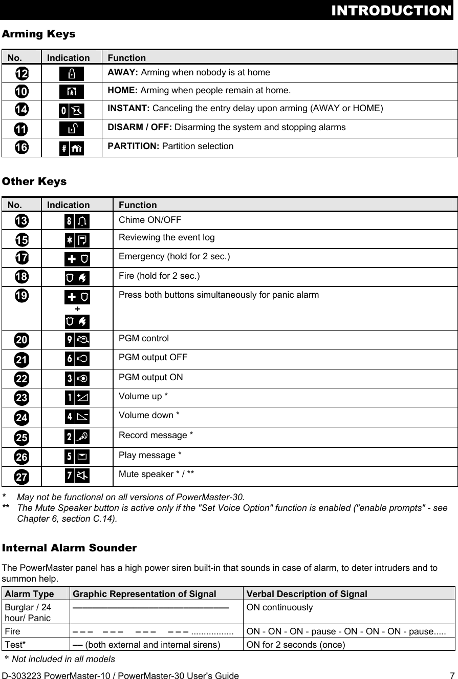
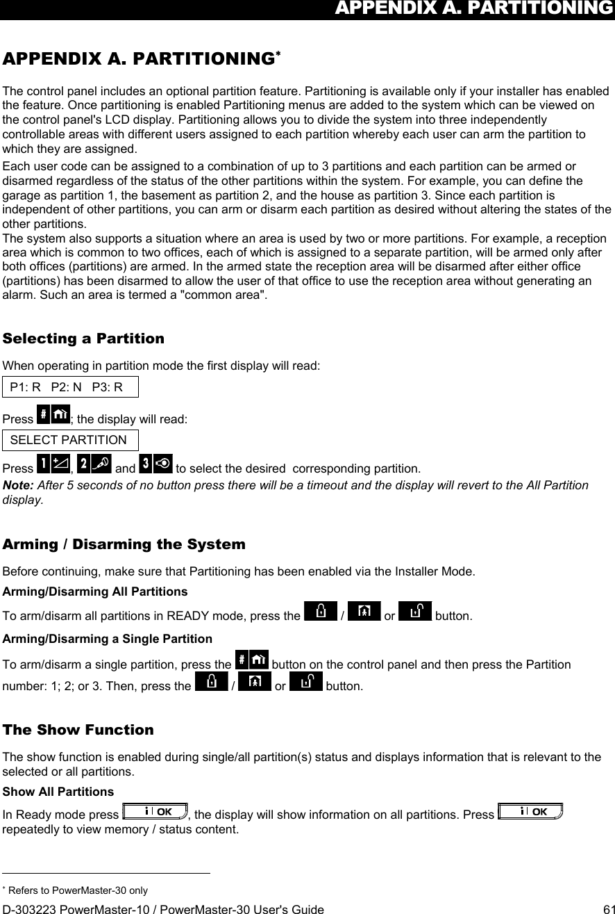
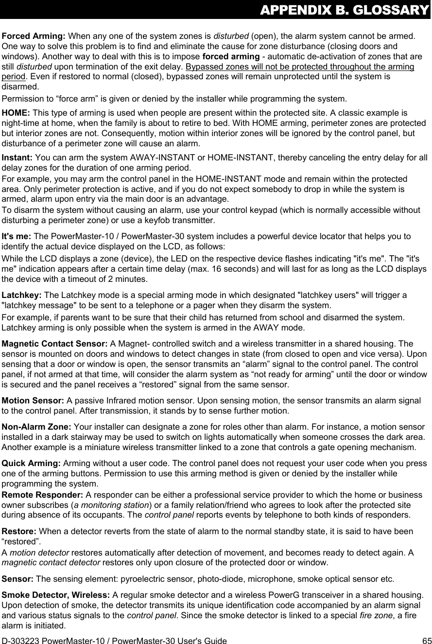
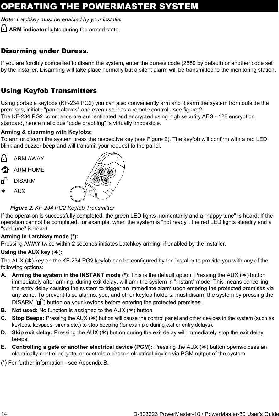
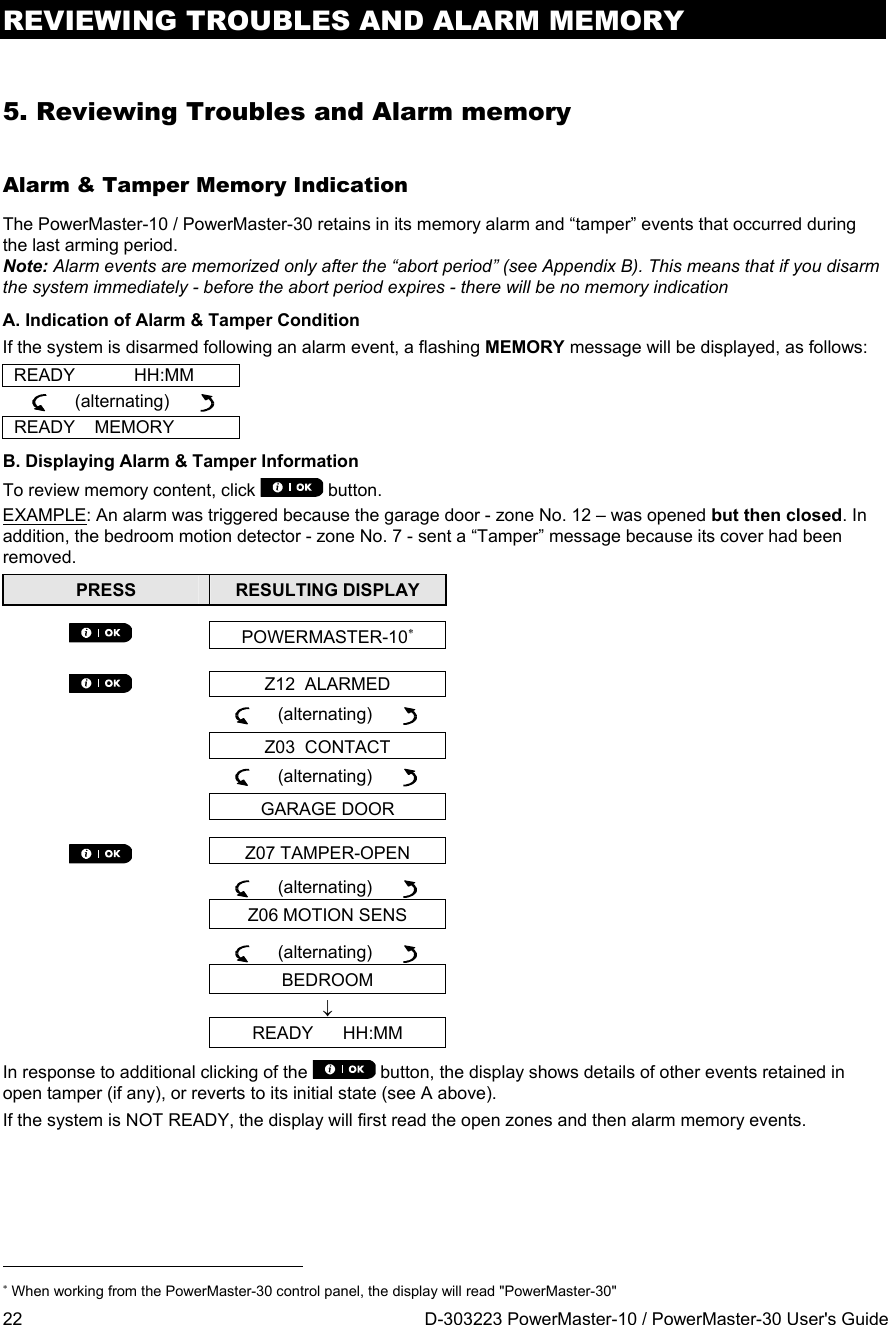
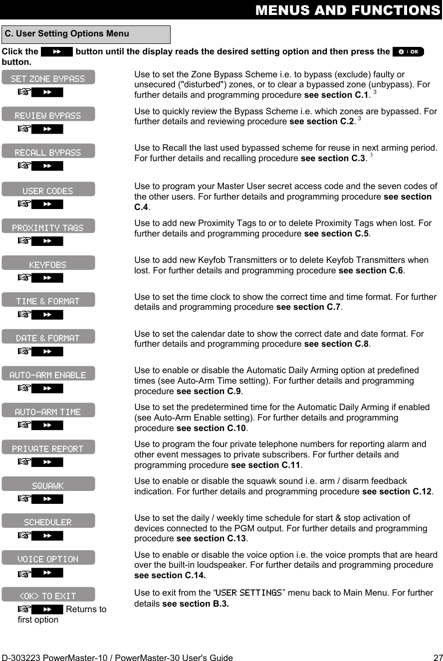
![OPERATING THE POWERMASTER SYSTEM D-303223 PowerMaster-10 / PowerMaster-30 User's Guide 11 ENTER CODE _ _ _ _ Arming ‘AWAY’ If the system is READY and quick arming is allowed, proceed as shown: PRESS RESULTING DISPLAY ARMING AWAY PLEASE EXIT NOW Vacate the premises (Exit delay) AWAY ARM indicator lights steadily during the armed state. Arming ‘HOME' If all perimeter zones are READY, and quick arming is allowed, proceed as shown: PRESS RESULTING DISPLAY ARMING HOME Move to interior zone (Exit delay) AWAY HH:MM ARM indicator flashes during the armed state. Disarming and Stopping Alarm Enter the protected premises via a delayed zone. Upon detecting your entrance, the system will start sounding the entry delay beeps alerting you to disarm the system before the entry delay ends. To disarm the system proceeds as shown: PRESS RESULTING DISPLAY CODE _ _ _ _ [Enter Code] Code READY HH:MM ARM indicator extinguishes during the disarmed state. Disarming the system also stops the siren alarm, irrespective of whether the alarm was initiated during the armed or the disarmed state. Disarming after an Alarm or Trouble After disarming, different displays may appear indicating that the system is in a state of TROUBLE (TRBL) or alarm MEMORY and will also sound trouble beeps once per minute. To find out the troubles that have been detected, or which zone alarmed, see Chapter 5. Reviewing Troubles and Alarm memory. Upon eliminating the cause for trouble the TRBL display will disappear, the TROUBLE indicator will extinguish and the trouble beeps will stop. The MEMORY message will disappear only upon rearming the system. IMPORTANT! If the trouble beeps bother you, disarm the system again (even though it is already disarmed). This will cancel the trouble beeps for 4 hours.](https://usermanual.wiki/Visonic/PMASTER20G2.manual/User-Guide-1540038-Page-11.png)
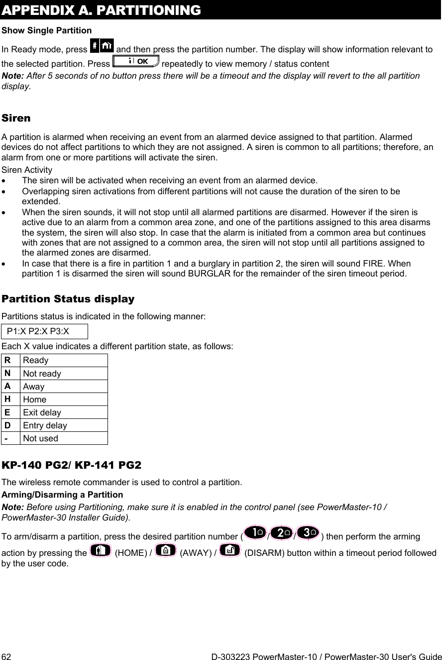
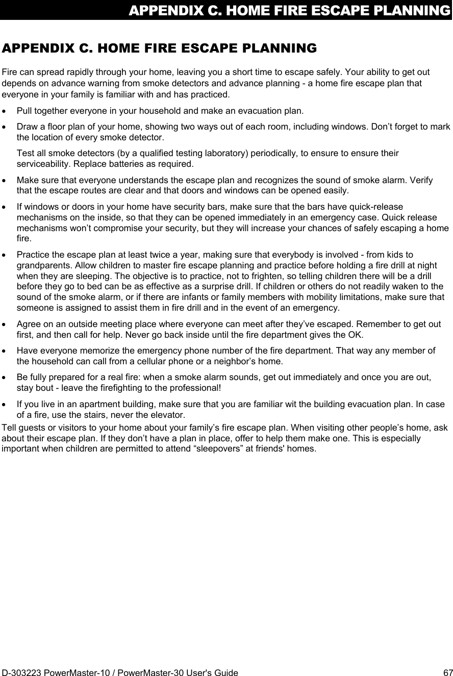
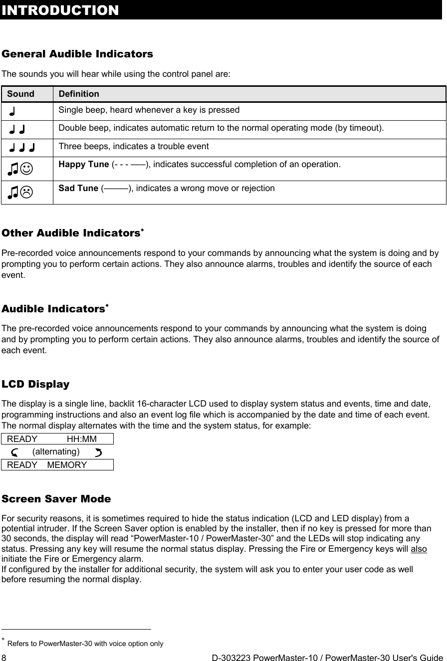
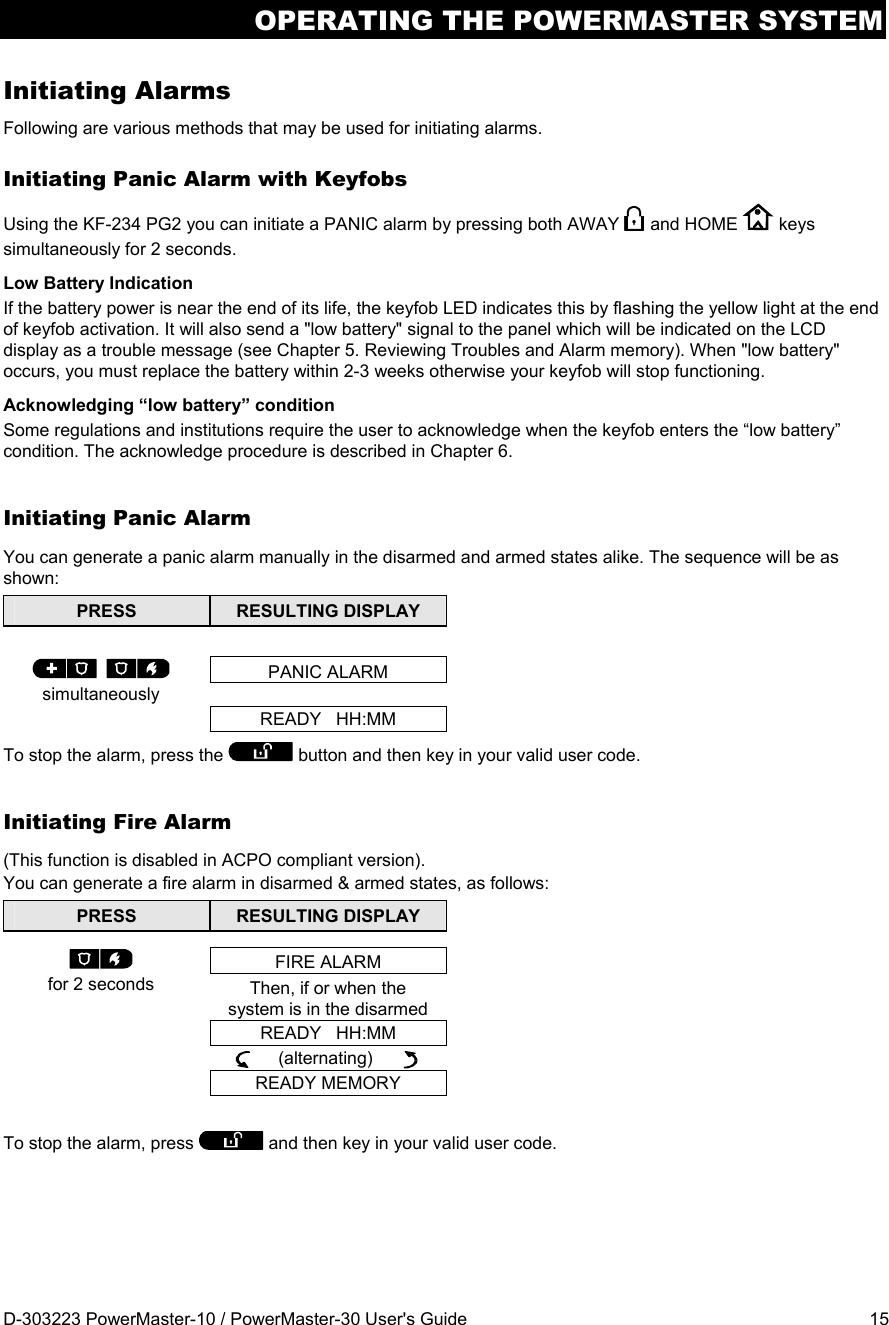
![OPERATING THE POWERMASTER SYSTEM 12 D-303223 PowerMaster-10 / PowerMaster-30 User's Guide Special Arming & Disarming Options In addition to basic arming, PowerMaster-10 / PowerMaster-30 provides you with several advanced arming and disarming options: Switching from ‘HOME’ to ‘AWAY’ Do not disarm the system - just press . The response will be the same as in ARMING AWAY above. Vacate the premises before the exit delay expires. Switching from ‘AWAY’ to ‘HOME’ Do not disarm the system - simply press . Since this operation reduces the security level, the PowerMaster-10 / PowerMaster-30 will ask you to key in your master user code or user code, thus making sure that you are an authorized user. PRESS RESULTING DISPLAY ENTER CODE _ _ _ _ [Enter code] Code ARMING HOMEMove to interior zone (Exit delay) ARM HOME HH:MM ARM indicator flashes during the armed state. Arming AWAY or HOME ‘Instant’ Pressing the button during the exit delay will arm the system in the "Instant' mode, i.e. without an entry delay. Therefore, any detection in any zone will trigger an immediate alarm. If you wish to arm AWAY-INSTANT, proceed as follows. PRESS RESULTING DISPLAY ENTER CODE _ _ _ _ Code ARMING AWAY ARMING INSTANT (alternating) PLEASE EXIT NOW Vacate the premises (Exit delay) AWAY ARM indicator lights during the armed state. Forced Arming AWAY or HOME Forced arming allows you to arm the system even if one or more zones are disturbed and the "NOT READY" message is displayed. Automatic forced arming operates only if this option was enabled by the installer while programming your system. All disturbed zones will be automatically bypassed - they will not be armed. The protected site will not have maximum protection.](https://usermanual.wiki/Visonic/PMASTER20G2.manual/User-Guide-1540038-Page-12.png)
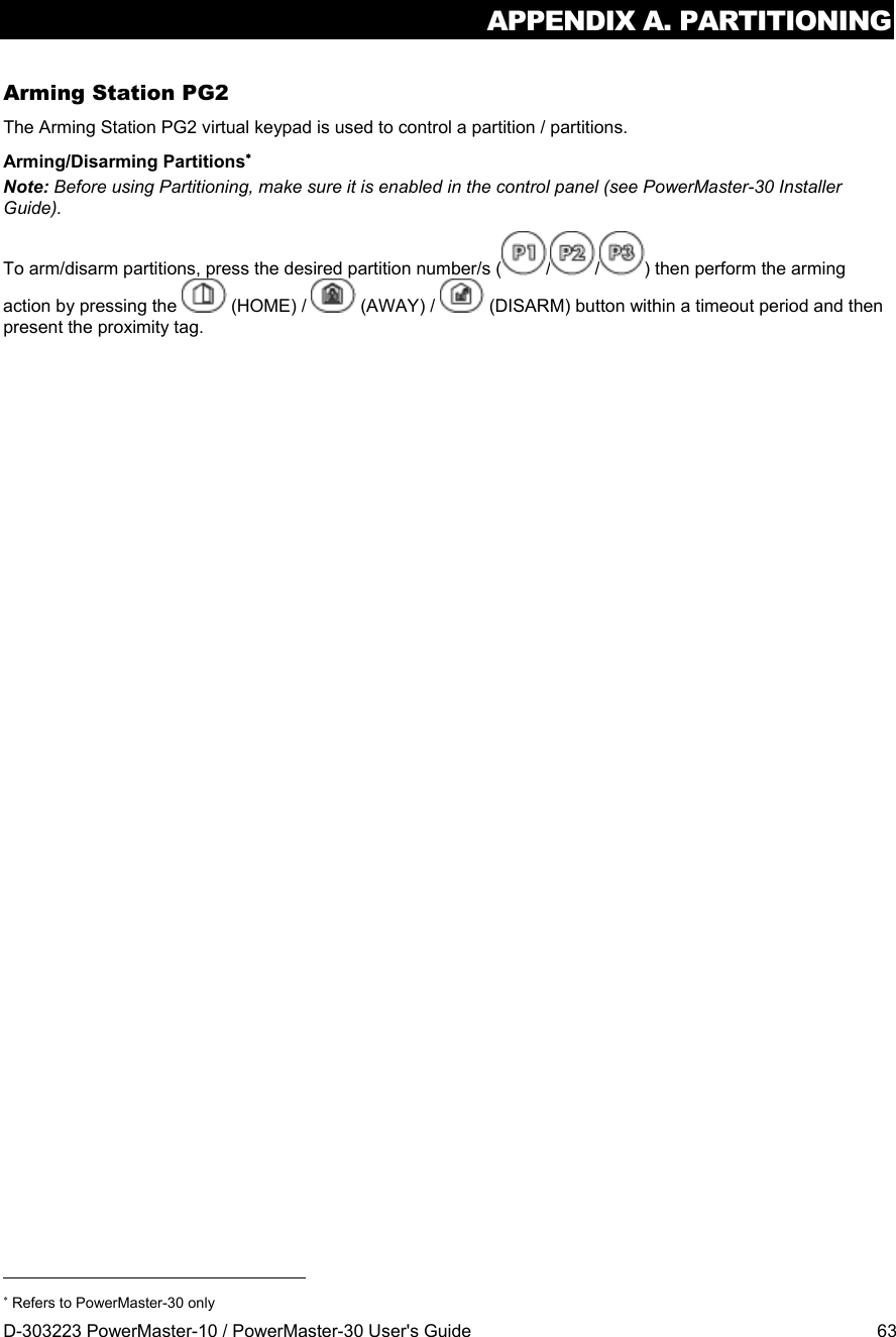
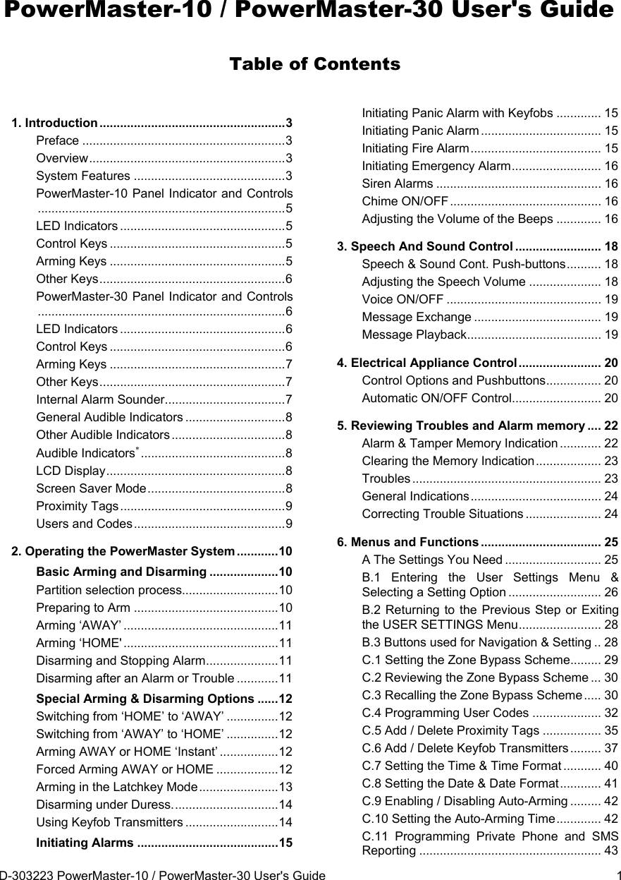
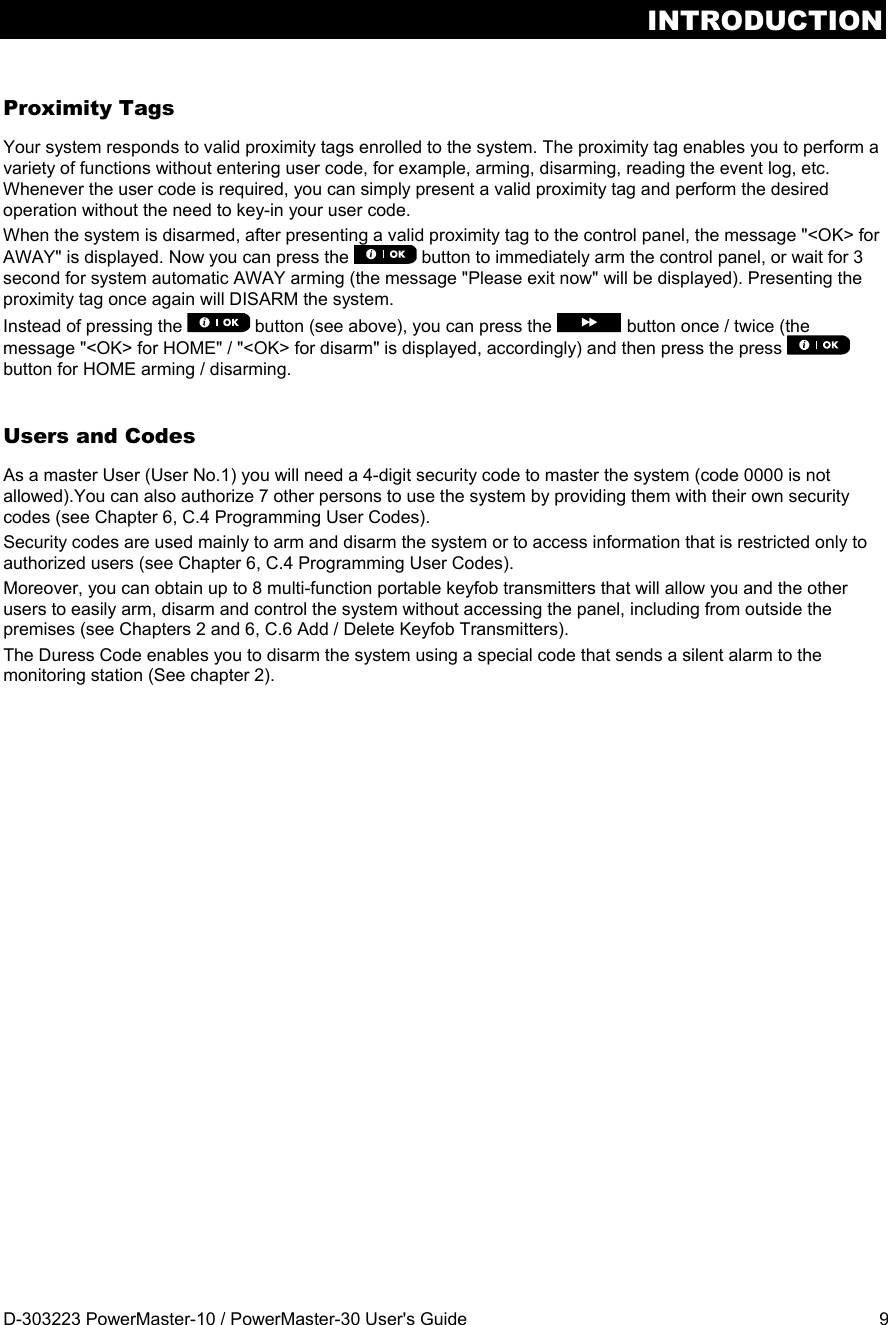
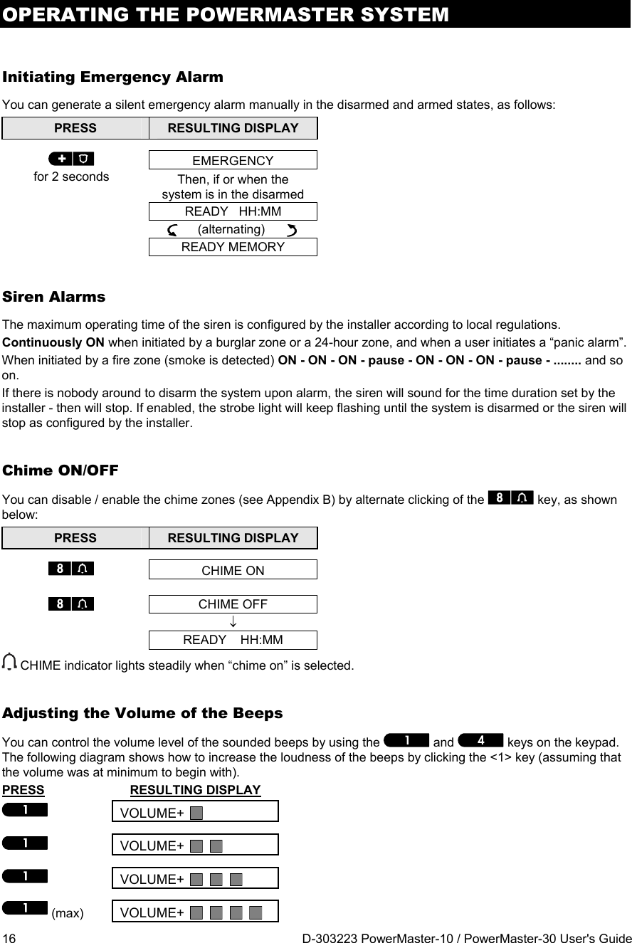
![OPERATING THE POWERMASTER SYSTEM D-303223 PowerMaster-10 / PowerMaster-30 User's Guide 13 Note: When forced arming is carried out, the buzzer “protests” by emitting a continuous tone during the exit delay until the last 10 seconds of the delay. You can silence this signal by pressing the arming button again. If forced arming is enabled and you wish to arm the system when NOT READY is displayed, proceed as shown: PRESS RESULTING DISPLAY ENTER CODE _ _ _ _ [Enter code] Code ARMING AWAY PLEASE EXIT NOW (to mute the buzzer) Vacate the premises (Exit delay) AWAY ARM indicator lights during the armed state. Remember: Forced arming compromises security!! Forced arming “HOME” is performed in a similar manner, as follows: PRESS RESULTING DISPLAY ENTER CODE _ _ _ _ [Enter code] Code ARMING HOME PLEASE EXIT NOW (to mute the buzzer) Go to interior zone (Exit delay) HOME HH:MM ARM indicator flashes during the armed state. Arming in the Latchkey Mode This mode, if enabled by the installer, is useful for a parent at work who wants to be sure that his children have returned from school and have disarmed the system. A special “latchkey” message will be sent out when the system is disarmed by a “latchkey user”. Latchkey users are holders of user codes 5 through 8 (PowerMaster-10) / user codes 23-32 (PowerMaster-30) or users of Keyfob transmitters 5 through 8 (PowerMaster-10) / 23-32 (PowerMaster-30). The latchkey message is considered an alert and not an alarm, and is therefore sent to the private telephones programmed by the user as targets for alert messages. Latchkey arming is possible only when you arm “AWAY”. To arm in the Latchkey mode, proceed as follows: PRESS RESULTING DISPLAY ARMING AWAY ARMING LATCHKEY (Within 2 seconds) (alternating) PLEASE EXIT NOW Vacate the premises (Exit delay) AWAY](https://usermanual.wiki/Visonic/PMASTER20G2.manual/User-Guide-1540038-Page-13.png)
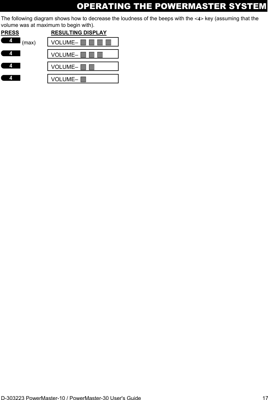
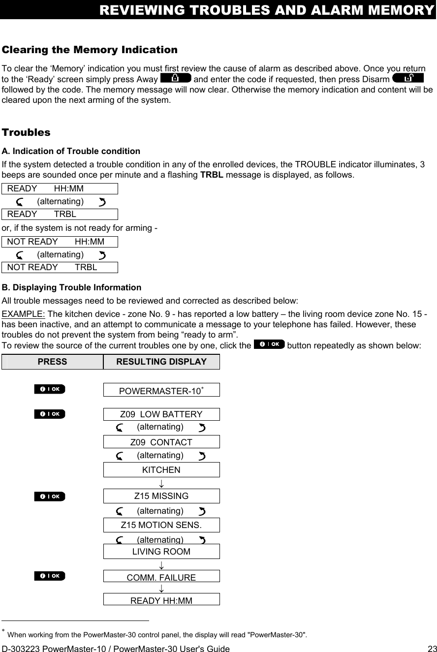
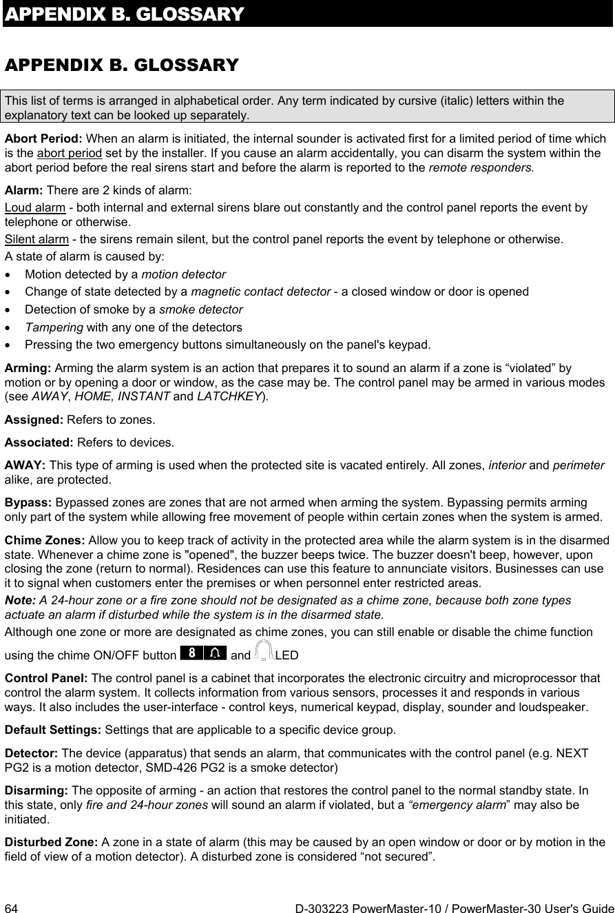
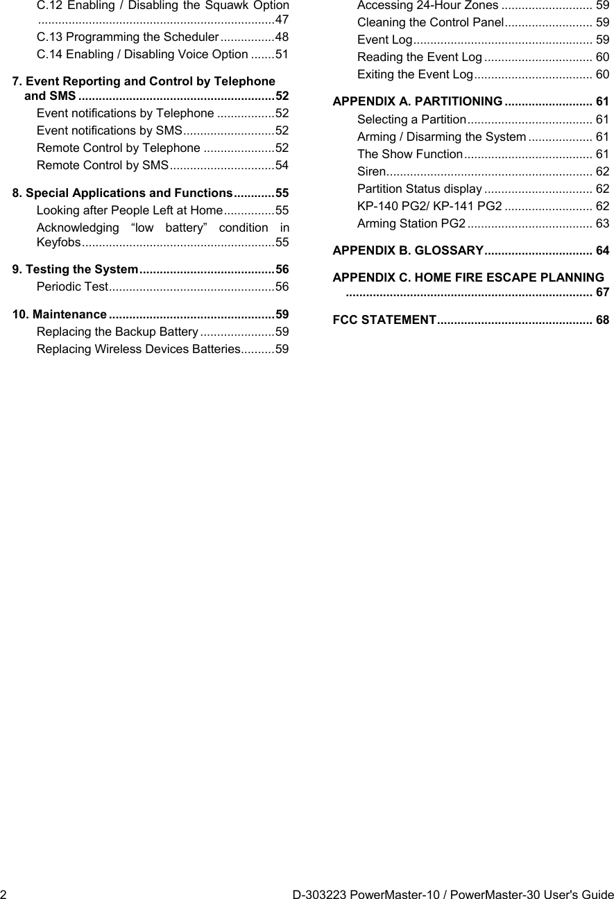
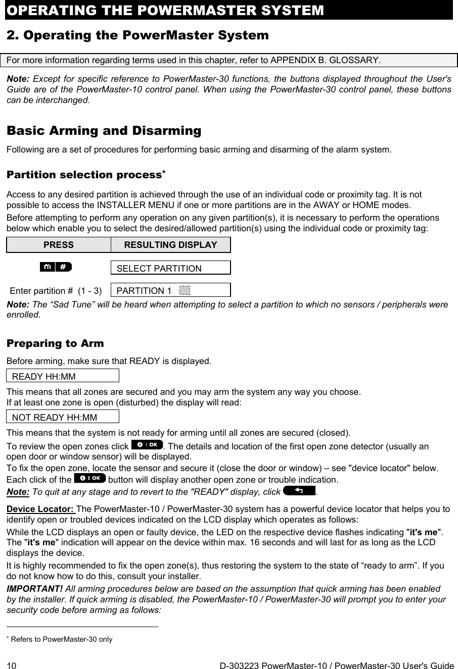
![MENUS AND FUNCTIONS 26 D-303223 PowerMaster-10 / PowerMaster-30 User's Guide B.1 Entering the User Settings Menu & Selecting a Setting Option The following procedure describes how to enter and move within the User Settings menu. Detailed descriptions of the User Setting options are provided at the end of the procedure. To exit the User Settings menu – see section B.2. 1. You can enter the "User Settings" menu only when the system is disarmed. 2. Carefully read the section titled "Additional Information" according to the indicated references 1 etc – see table at end of this section. Note: Except for specific reference to PowerMaster-30 functions, the buttons displayed throughout the User's Guide are of the PowerMaster-10 control panel. When using the PowerMaster-30 control panel, these buttons can be interchanged. A. To Enter the User Settings Menu 1. Make sure the system is disarmed and then press the button repeatedly until the display reads "USER SETTINGS". 1 2. Press to confirm The screen will now prompt you to enter your user code. 3. CODE Enter your User Code. 2 The display reads the first Setting option of the User Settings menu [SET BYPASS]. 3 B. To Select a Setting Option 4. or Click the or button until the display reads the desired setting option, for example, "TIME & FORMAT". 5. When the desired setting option appears on the display, press the button to enter the setting process. Continue to the selected setting option in C.1 - C.14 The remainder of the procedures for the selected setting options is provided in sections C.1 to C.14. Additional Information (section B.1) 1 Display shown in disarm state when all zones are secured (00:00 or other digits show present time). 2 a. If you have not already changed your personal code number, use the default setting – 1111. b. The Master User has access to all User Settings options. All other users have access only to the Bypass options. c. Do not set any user code the same as an installer code. 3 The bypass options will be displayed in the User Settings menu only if enabled by the installer. Otherwise, the first user setting option displayed will be [USER CODES]. SET BYPASS TIME & FORMAT SET BYPASS ENTER CODE: USER SETTINGS READY 00:00](https://usermanual.wiki/Visonic/PMASTER20G2.manual/User-Guide-1540038-Page-26.png)
![MENUS AND FUNCTIONS 28 D-303223 PowerMaster-10 / PowerMaster-30 User's Guide B.2 Returning to the Previous Step or Exiting the USER SETTINGS Menu During the setting process it is frequently necessary to return to the previous setting step or option (i.e. "to go one level up") or to exit the User Settings menu. A. To Move One Level Up To move one level up during the setting process, click the button once or more. Each click will take you one level up or to the previous setting step: B. To Exit the USER SETTINGS Menu To exit "USER SETTINGS", move up the menu by pressing the button repeatedly (see above) until the display reads [<OK> TO EXIT] or preferably; press the button once which brings you immediately to the exit screen [<OK> TO EXIT]. or When the display reads [<OK> TO EXIT], press The system exits the “USER SETTINGS" menu and returns to the normal disarm state while showing the READY display. B.3 Buttons used for Navigation & Setting The keypad's buttons are used for various functions when programming. The following table provides a detailed description of the function or use of each button. Button Definition Navigation / Setting Function NEXT Use to move / scroll forward to the next menu options. BACK Use to move / scroll backward to the previous menu options. OK Use to select a menu option or to confirm a setting or action. HOME Use to move one level up in the menu or to return to previous setting step. AWAY Use to jump back to the [<OK> TO EXIT] screen to quit programming. OFF Use to cancel, delete, clear or erase setting, data, etc. 0 - 9 Numerical keypad used to enter numerical data. Any screen READY 12:00 <OK> TO EXIT](https://usermanual.wiki/Visonic/PMASTER20G2.manual/User-Guide-1540038-Page-28.png)
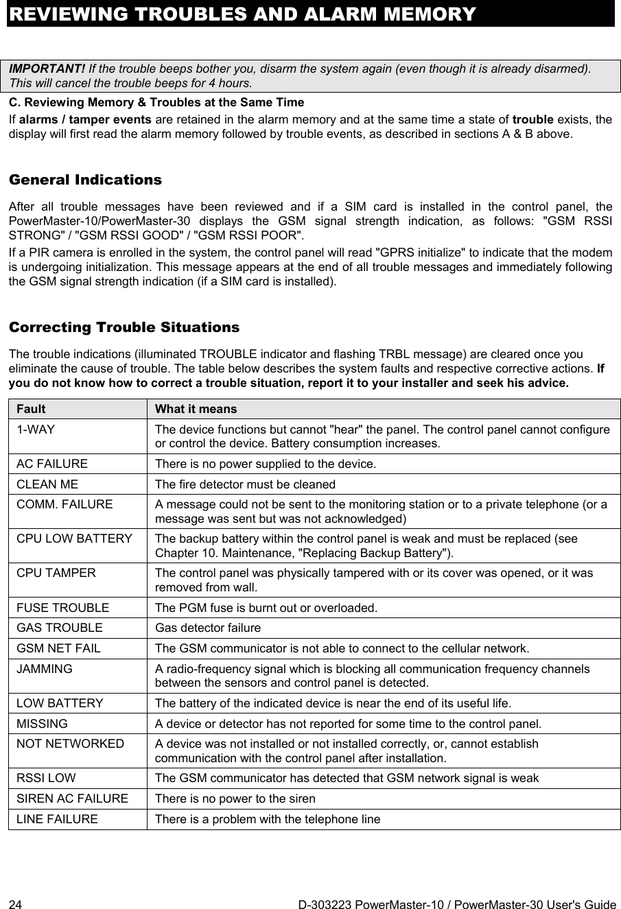
![MENUS AND FUNCTIONS D-303223 PowerMaster-10 / PowerMaster-30 User's Guide 29 C.1 Setting the Zone Bypass Scheme Bypassing permits arming only part of the system while allowing free movement of people within certain zones when the system is armed. It is also used to temporarily remove from service faulty zones that require repair work or to deactivate a sensor if, for example, you are decorating a room. Here you can set the Zone Bypass Scheme i.e. to scroll through the list of registered (enrolled) sensors to your PowerMaster-10 / PowerMaster-30 system and to Bypass (deactivate) faulty or disturbed sensors (either READY or NOT-READY) or to Clear (reactivate) BYPASSED zones (sensors). Once you have set a Bypass Scheme you can use the following 3 options: > To quickly review the bypassed zones – refer to section C.2. > To quickly clear a bypassed zone i.e. to reactivate the bypassed zone – refer to section C.2. > To repeat (recall) the last used zone bypassing scheme – refer to section C.3. 1. Zones will be bypassed throughout one disarm-arm period only. Disarming the system after arming will suspend the entire bypassing scheme but you can recall and reuse it as described in section C.3. 2. Fire zones cannot be bypassed. 3. Carefully read the section titled "Additional Information" according to the indicated references 1 etc – see table at end of section C.3. REMEMBER – ZONE BYPASSING COMPROMISES SECURITY! A. To Bypass a Zone 1. Enter the USER SETTINGS menu and select the [SET ZONE BYPASS] option and press the button to confirm. 1 The first zone, Z01, is displayed. 2 2. or Click the or button until the display reads the zone you wish to bypass (or clear bypass), for example, "Z04" for Zone 04. After several seconds the LED on the respective device starts flashing indicating "it's me". 3. When the display reads the zone you wish to bypass press to confirm. 4. The display now reads [<OK> TO BYPASS]. 3 To bypass the selected zone press 5. A "Happy Tune" ☺ sounds and the updated zone status is now displayed i.e. [Z04: BYPASSED]. 5 Z04: BYPASSED <OK> TO BYPASS Kitchen Z04: NOT READY Living Room Z01: READY SET ZONE BYPASS](https://usermanual.wiki/Visonic/PMASTER20G2.manual/User-Guide-1540038-Page-29.png)
![MENUS AND FUNCTIONS 30 D-303223 PowerMaster-10 / PowerMaster-30 User's Guide B. To Clear a Bypassed Zone 6. Repeat steps 1 to 2 above. 7. When the zone you wish to clear bypass appears on the display (for example, "Z04"), press to confirm. You can also identify the device by looking for the "it's me" LED indication on the displayed device. The display now reads [<OFF> TO CLEAR]. 3 8. To clear the bypassed zone press the button. A "Happy Tune" ☺ sounds and the updated zone status is now displayed, i.e. [Z04: READY] or [Z04: NOT READY]. 6 C.2 Reviewing the Zone Bypass Scheme Here you can quickly review the Bypass Scheme i.e. the zones that are set to be bypassed during the next arming session. 1. Enter the USER SETTINGS menu and select the [REVIEW BYPASS] option and press the button to confirm. 1 2. The display reads [BYPASS LIST] or Click the or buttons repeatedly to review all bypassed zones in ascending numerical order. When done, click the button to exit. 63. C.3 Recalling the Zone Bypass Scheme Use this option to repeat (recall) the most recent Bypassed Scheme for use during the next arming session. 1. Enter the USER SETTINGS menu, select the [RECALL BYPASS] option and press the button to confirm. 1 2. The display now reads [<OK> TO RECALL]. 4 To recall the last used bypass scheme press . 3. ☺ Return to step 1 A "Happy Tune" ☺ sounds. The display reads [Bypass RECALLED] and then returns to “USER SETTINGS" step 1. 6 Z04: READY Kitchen BYPASS LIST Z04: BYPASSED Bypass RECALLED <OK> TO RECALL RECALL BYPASS Z04: BYPASSED REVIEW BYPASS Kitchen <OFF> TO CLEAR](https://usermanual.wiki/Visonic/PMASTER20G2.manual/User-Guide-1540038-Page-30.png)
![MENUS AND FUNCTIONS D-303223 PowerMaster-10 / PowerMaster-30 User's Guide 31 Additional Information (section C.1 – C.3) 1 For detailed instructions on how to select User Settings – refer to section B.1 and section B.2. 2 a. The STATUS to the right of the zone number indicates whether the zone is READY, NOT-READY or BYPASSED. b. In the example on the left the display reads [Z01: READY] alternating with [Living Room]. 3 a. If the zone you selected is "not bypassed", the display prompts you to press [<OK> TO BYPASS]. However, if the zone you selected is already "bypassed", the display prompts you to press [<OFF> TO CLEAR]. b. To abort and return to the previous step press or 4 The display now prompts you to press [<OK> TO RECALL] i.e. to repeat the last used bypass scheme. If you wish to abort and return to the User Setting menu, press . 5 You can now repeat steps 2 - 5 to bypass or clear another zone. To end this session and to select other menu options or to quit programming - follow the instructions in section B.2. 6 You can now select another option in the User Setting menu (see section B.1), or quit programming (see section B.2).](https://usermanual.wiki/Visonic/PMASTER20G2.manual/User-Guide-1540038-Page-31.png)
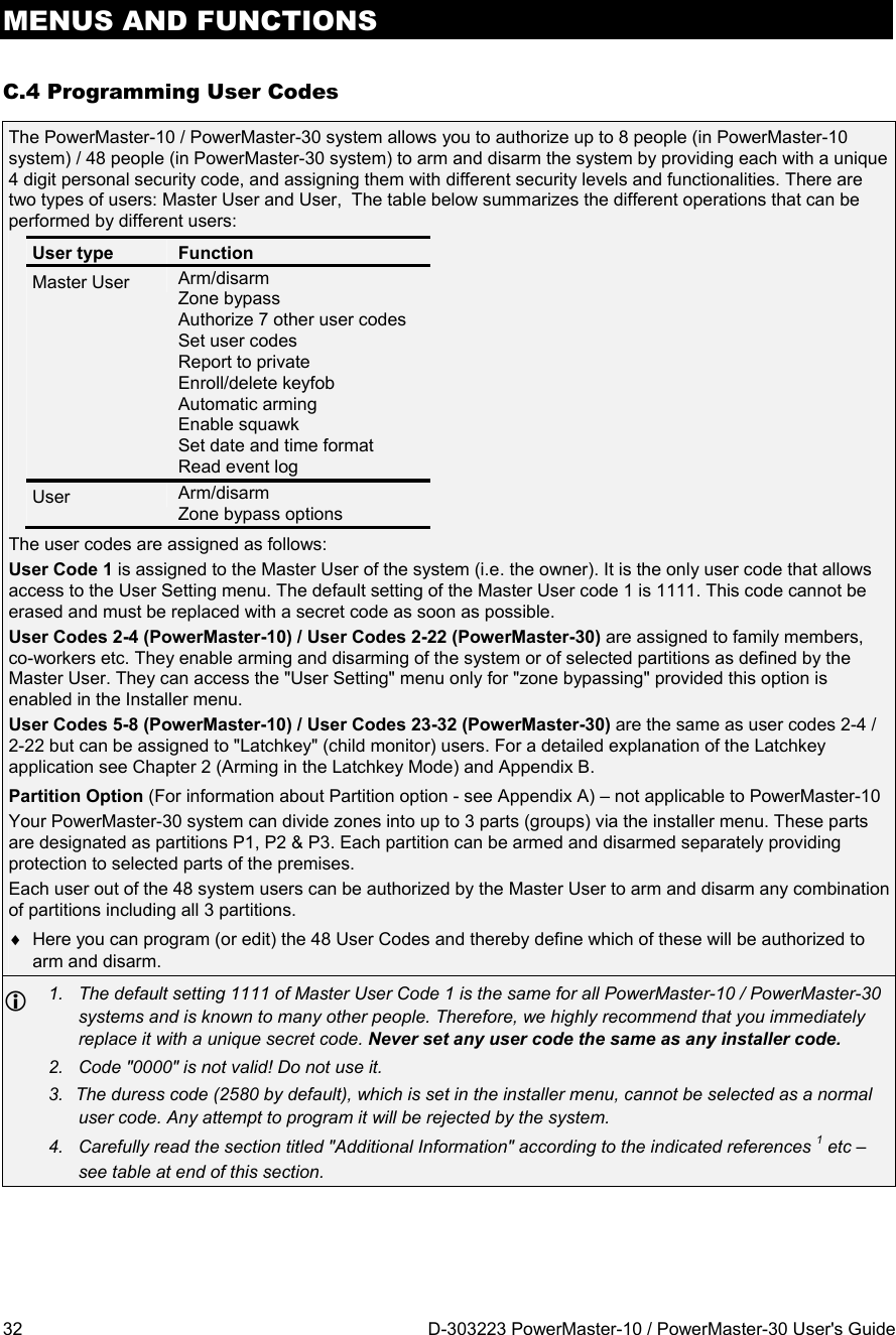
![MENUS AND FUNCTIONS D-303223 PowerMaster-10 / PowerMaster-30 User's Guide 33 A. To Program a User Code B. To Set Partitions Authorization Refers to PowerMaster-30 only 1. Enter the USER SETTINGS menu, select the [USER CODES] option and press the button to confirm. 1 2. The first user code "User 01 Code" is displayed. 2 or At the blinking cursor position, key in the User Code you wish to program , for example, [2+6] for user code 26, or alternatively click the or button until the display reads, "User 26 Code". 3. When the user code you wish to program appears on the display, press to confirm. 4. To program or edit the code, at the blinking cursorposition enter the 4 digit code, for example, “1234”, using the numerical keypad. 3, 4 5. When done, press to confirm. ☺ Return to step 3 A "Happy Tune" ☺ sounds. The display confirms the saved code. 5, 6 6. The display will read [SET PARTITIONS]. 7 7. Use the keypad keys , , to change the status of the partitions P1, P2 & P3, respectively. 8 When you are satisfied with the setting, for example, User 4 is authorized with Partition 1 and 3 only, press to confirm. ☺ Return to step 3 A "Happy Tune" ☺ sounds. The display confirms the Partition setting. 9 U26: P1 P2 P3 U26: P1 P2 P3 SET PARTITIONS User 26 5327 User 26 : 5327 User 26 Code User 01 Code USER CODES](https://usermanual.wiki/Visonic/PMASTER20G2.manual/User-Guide-1540038-Page-33.png)
![MENUS AND FUNCTIONS D-303223 PowerMaster-10 / PowerMaster-30 User's Guide 35 C.5 Add / Delete Proximity Tags Each of the 8 PowerMaster-10 / PowerMaster-30 users may be provided with a proximity tag that can be used instead of the user codes to perform a variety of functions, for example, arming, disarming, reading the event log, etc. Whenever a user code is required you can simply present a valid proximity tag instead of entering the user code. Each tag should be assigned with a serial No. 1-8 (PowerMaster-10) / 1-32 (PowerMaster-30) that corresponds to the User Code No. 1-8 (PowerMaster-10) / 1-32 (PowerMaster-30) and enrolled into the system correspondingly. The partition authorization of the tags is identical to their corresponding user codes. For example, proximity tag 3 is assigned to user code 3. Here you can add (enroll) new proximity tags or delete tags as required. Carefully read the section titled "Additional Information" according to the indicated references1 etc – see table at end of this section. A. To Add (Enroll) a Proximity Tag 1. Enter the USER SETTINGS menu, select the [PROXIMITY TAGS] option and press the button to confirm. 1 2. The display will read [ADD NEW TAG]. 3 To begin the process of enrolling a new proximity tag press . 3. Present the proximity tag to the control panel within the timeout period. 4. ☺ Go to step 5 If enrollment was successfully completed, a "Happy Tune" ☺ sounds and the display reads [DEVICE ENROLLED] for a short duration and then changes to read the tag's details. 4 5. The display shows the allocated tag serial No (user No.), which is always the first free number, for example: [T01:Tag (Prox)]. or If you wish to assign the tag to another user, for example, "User No. 5", key in [0+5] or alternatively click the or button until the display reads [T05:Tag (Prox)] and then press to confirm. ☺ Return to step 2 The display reads [DEVICE ENROLLED] a "Happy Tune" ☺ sounds and the display will then change to [T01:Tag (Prox)]. 7 Refers to PowerMaster-30 only T05:Tag (Prox) T01:Tag (Prox) ENTR ID:xxx-xxxx DEVICE ENROLLED ENROLL NOW or ADD NEW TAG PROXIMITY TAGS](https://usermanual.wiki/Visonic/PMASTER20G2.manual/User-Guide-1540038-Page-35.png)
![MENUS AND FUNCTIONS 36 D-303223 PowerMaster-10 / PowerMaster-30 User's Guide B. To Delete a Proximity Tag 1. Enter the USER SETTINGS menu, select the [PROXIMITY TAG] option and press the button to confirm. 1 2. The display will read [ADD NEW TAG]. Click the button until the display reads [DELETE TAG]. 3. Press to confirm. The display will read [T01:Tag (prox)] alternating with the ID number of the tag. 2, 5 4. or Key in the tag number you wish to delete, for example, [0+6] or alternatively click the or button until the display reads the tag number, "T06:Tag (prox)" and "ID No. 300-2564". When the tag you wish to delete appears on the display, press . 5. The display now reads [<OFF> to delete].6 6. To delete the tag press the button. ☺ Go to step 3 A "Happy Tune" ☺ sounds and the display reads [DELETE TAG] and returns to step 3. 8 Additional Information (section C.5) 1 For detailed instructions on how to select User Settings – refer to section B.1 and section B.2. 2 The display shows the 1st Tag (Tag No.1) of the 8 tags. 3 To abort enrollment press the button. 4 If the tag was previously enrolled in the system, the PowerMaster-10 / PowerMaster-30 display reads "ALREADY ENROLLED" and then switches to the name of the tag alternating with its ID number. 5 If no proximity tag is enrolled in the system, the display reads "NO EXISTING DEV.". 6 If you wish to abort the procedure, press the button. 7 You can now enroll another proximity tag. You can also select another option in the User Setting menu (see section B.1 and section B.2), or quit programming (see section B.3). 8 You can now add or delete another proximity tag. You can also select another option in the User Setting menu (see section B.1 and section B.2), or quit programming (see section B.3). ADD NEW TAG PROXIMITY TAG DELETE TAG <OFF> to delete K06:Tag (prox) T01:Tag (prox) DELETE TAG](https://usermanual.wiki/Visonic/PMASTER20G2.manual/User-Guide-1540038-Page-36.png)
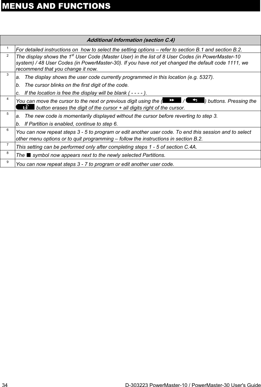
![MENUS AND FUNCTIONS D-303223 PowerMaster-10 / PowerMaster-30 User's Guide 37 C.6 Add / Delete Keyfob Transmitters Each of the 8 PowerMaster-10 / PowerMaster-30 users may be provided with a portable keyfob transmitter to exercise better, quicker and safer arming/disarming and other control functions. Each keyfob should be assigned with a serial No. 1-8 (PowerMaster-10) / 1-32 (PowerMaster-30) and enrolled into the system correspondingly. Partition Option (For information about Partition option - see Appendix A) If the Partition option is enabled in the control panel, each of the 32 keyfobs can be authorized by the Master User to arm and disarm any combination, or all 3 partitions, irrespective of the authorization of its corresponding user code. Here you can add (enroll) the 8 (PowerMaster-10) / 32 (PowerMaster-30) Keyfob transmitters and define which of the 3 partitions each of the keyfob will be authorized to arm and disarm, or delete keyfobs as required. 1. Before anything else, gather up all keyfob units you intend to enroll and make sure they all have batteries installed and that they are active (the LED blinks upon pressing any of the buttons). 2. Carefully read the section titled "Additional Information" according to the indicated references1 etc – see table at end of this section. A. To Add (Enroll) a Keyfob 1. Enter the USER SETTINGS menu, select the [KEYFOBS] option and press the button to confirm. 2 2. The display will read [ADD NEW KEYFOB]. 4 To enroll a new keyfob press . 3. The display offers you two alternative methods to enroll a keyfob: A: ENROLL NOW: Press and hold the AUX button on the selected keyfob until the LED is constantly on. 1 This procedure completes the enrollment. 4a. ☺ Go to step 5 If enrollment was successfully completed, a "Happy Tune" ☺ sounds and the display reads [DEVICE ENROLLED] for a short duration and then changes to read the keyfob's details. Continue to step 5. 5 4b. B: ENTER ID (Pre-enrollment): Enter the 7-digit number that appears on the keyfob sticker and then press to confirm. To complete the enrollment procedure see note 6 in the Additional Information table below. 7 ☺ Go to step 5 If a valid ID was entered, a "Happy Tune" ☺ sounds and the display reads [ID ACCEPTED] for a short duration and then changes to read the keyfob's details. Continue to step 5.5. The display shows the allocated keyfob serial No (user No.), which is always the first free number, and the keyfob's ID number; for example: [F01:Keyfob] alternating with [ID No. 300-5786]. or If you wish to assign the keyfob to another user, for example, "User No. 5", ", Refers to PowerMaster-30 only ID No. 300-5786 F01:keyfob ID ACCEPTED ENTR ID:xxx-xxxx ID No. 300-5786 DEVICE ENROLLED ENROLL NOW or ADD NEW KEYFOB KEYFOBS](https://usermanual.wiki/Visonic/PMASTER20G2.manual/User-Guide-1540038-Page-37.png)
![MENUS AND FUNCTIONS 38 D-303223 PowerMaster-10 / PowerMaster-30 User's Guide key in [2+5] or alternatively click the or button until the display reads [F25:Keyfob] and then press to confirm. ☺ Return to step 2 The display reads [DEVICE ENROLLED] or [ID accepted] if the keyfob was enrolled manually by entering the ID number, a "Happy Tune" ☺ sounds and the display will then change to [F01:Keyfob]. B. To Delete a Keyfob 1. Enter the USER SETTINGS menu, select the [KEYFOBS] option and press the button to confirm. 2 2. The display will read [ADD NEW KEYFOB]. Click the button until the display reads [DELETE KEYFOB]. 3. Press to confirm. The display will read [F01:Keyfob] alternating with the ID number of the keyfob. 3 4. or Key in the keyfob number you wish to delete, for example, [0+6] or alternatively click the or button until the display reads the keyfob number, for example, "F06:Keyfob" and "ID No. 300-5799". When the keyfob you wish to delete appears on the display, press . 5 5. The display now reads [<OFF> TO DELETE]. 6 6. ☺ Go to step 3 To delete the keyfob press the button. A "Happy Tune" ☺ sounds and the display reads [DELETE KEYFOB] and returns to step 3. 8 ID No. 300-5799 ADD NEW KEYFOB KEYFOBS F25:keyfob DELETE KEYFOB <OFF> TO DELETE F06:keyfob F01:keyfob DELETE KEYFOB](https://usermanual.wiki/Visonic/PMASTER20G2.manual/User-Guide-1540038-Page-38.png)
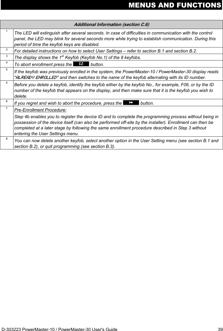
![MENUS AND FUNCTIONS 40 D-303223 PowerMaster-10 / PowerMaster-30 User's Guide C.7 Setting the Time & Time Format Here you can program or adjust the built-in-clock to show the correct time in the desired time format. You can select between a 24 hour and a 12 hour (AM/PM) time format. Carefully read the section titled "Additional Information" according to the indicated references1 etc – see table at end of this section. A. To Set the Time Format 1. Enter the USER SETTINGS menu and select the [TIME & FORMAT] option and press the button to confirm. 1 2. The display shows the currently selected time format. 2 or Click the or button until the display shows the desired time format, for example, "EU FORMAT-24H" and press to confirm . 3. B. To Set the Time 5 4. At the blinking cursor position, enter the correct time, for example, “8:55A”, using the numerical keypad. 45. When you are satisfied with the setting, press to confirm. ☺ Return to step 2 A "Happy Tune" ☺ sounds, the display reads the set time, returns to step 2 and then reads the selected time format. 6, 7 Additional Information (section C.7) 1 For detailed instructions on how to select User Settings – refer to section B.1 and section B.2. 2 a. The display shows the currently selected format (indicated by a symbol), for example, "24 Hrs". b. You can now select either the 12 Hrs or 24 Hrs time format using the or buttons. 3 The display shows the Time in the selected Time Format, for example, "12:40 PM", with the cursor blinking on the first hour digit "1". The letter that follows the displayed time indicates one of the following: "A" = AM; "P" = PM and "none" for 24 Hrs time format. When the curser is positioned on the AM/PM digit, you can set to "AM" with the button and the "PM" with the button 4 You can move the cursor to the next or previous digit using the or buttons. 5 This setting can be performed only after completing steps 1 – 3 of section C.7A. 6 The time saved is displayed without the cursor, for example, "08:55 A" followed by the selected time format. 7 You can now select another option in the User Setting menu (see section B.1 and section B.2), or quit programming (see section B.3). TIME 08:55A EU FORMAT-24H TIME 12:40P US FORMAT-12H TIME & FORMAT](https://usermanual.wiki/Visonic/PMASTER20G2.manual/User-Guide-1540038-Page-40.png)
![MENUS AND FUNCTIONS D-303223 PowerMaster-10 / PowerMaster-30 User's Guide 41 C.8 Setting the Date & Date Format Here you can program or adjust the built-in-calendar to show the correct date in the desired date format. You can select between a "mm/dd/yyyy" and a "dd/mm/yyyy" date format. Carefully read the section titled "Additional Information" according to the indicated references1 etc – see table at end of this section. A. To Set the Date Format 1. Enter the USER SETTINGS menu and select the [DATE & FORMAT] option and press the button to confirm. 1 2. The display shows the currently selected date format. 2 or Click the or button until the display reads the desired date format, for example, "DD/MM/YYYY" and press to confirm. 3. B. To Set the Date 7 4. At the blinking cursor position, enter the correct date, for example, “20.04.2011”, using the numerical keypad. 3, 4, 55. When you are satisfied with the setting, press to confirm. ☺ Return to step 2 A "Happy Tune" ☺ sounds, the display shows the set date and returns to step 2 and shows the selected date format. 6 Additional Information (section C.8) 1 For detailed instructions on how to select User Settings – refer to section B.1 and section B.2. 2 The display shows the currently selected format (indicated by a symbol), for example, "mm/dd/yyyy". You can now select either the "mm/dd/yyyy" or "dd/mm/yyyy" date format using the or button. 3 The display shows the Date and selected Date Format, for example, "30.12.2007", with the cursor blinking on the first digit. 4 You can move the cursor to the next or previous digit using the or button. 5 For the year, enter the two last digits only. 6 You can now select another option in the User Setting menu (see section B.1 and section B.2), or quit programming (see section B.3). 7 This setting can be performed only after completing steps 1 – 3 of section C.8A. DATE DD/MM/YYYY Date:20/04/2011 DATE 20/02/2008 DATE MM/DD/YYYY DATE & FORMAT](https://usermanual.wiki/Visonic/PMASTER20G2.manual/User-Guide-1540038-Page-41.png)
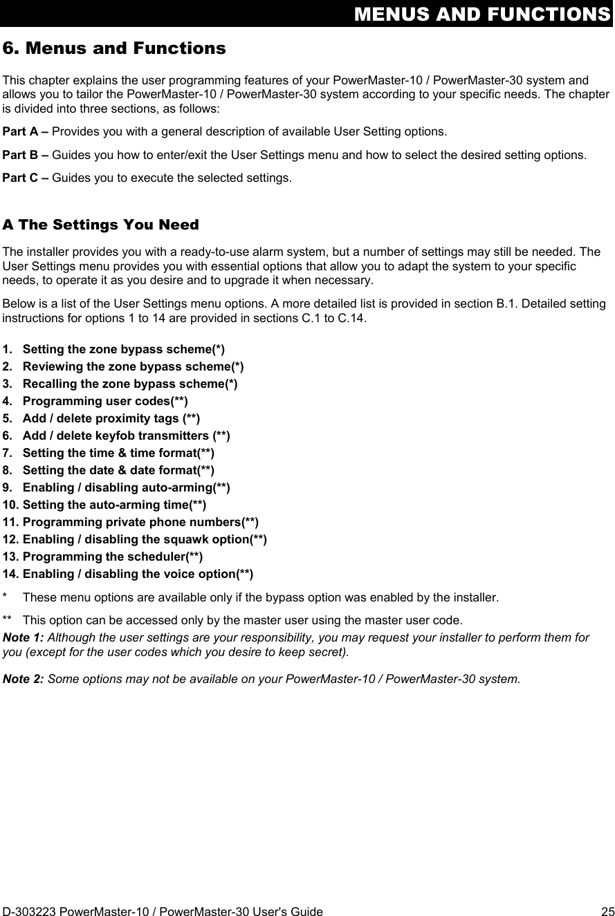
![MENUS AND FUNCTIONS 42 D-303223 PowerMaster-10 / PowerMaster-30 User's Guide C.9 Enabling / Disabling Auto-Arming The PowerMaster-10 / PowerMaster-30 system can be programmed to automatically arm itself on a daily basis at a predetermined time. This feature is useful especially in commercial applications, such as in stores, to ensure that the system is always armed and without having to assign security codes to employees. Here you can enable (activate) and disable (stop) the Auto-Arming. To set the Auto-Arming time – see section C.10. Carefully read the section titled "Additional Information" according to the indicated references1 etc – see table at end of this section. 1. Enter the USER SETTINGS menu, select the [AUTO-ARM ENABLE] option and press the button to confirm. 1 2. The display shows the currently selected setting. 2 or Click the or button until the display reads the desired setting, for example, "enable autoarm" and press to confirm. 3. ☺ Return to step 1 A "Happy Tune" ☺ sounds. The display confirms the saved setting, and then returns to the User Setting menu, step 1. 3 C.10 Setting the Auto-Arming Time Here you can program the exact time of the Auto-Arming. 1. Enter the USER SETTINGS menu, select the [AUTO-ARM TIME] option and press the button to confirm. 1 2. The display shows the current setting of the Auto-Arm Time. At the blinking cursor position, enter the correct time, for example, “8:30A”, using the numerical keypad. 4 3. When you are satisfied with the setting, press to confirm. ☺ Return to step 1 A "Happy Tune" ☺ sounds. The display confirms the saved time, then returns to the User Setting menu, step 1. 5, 6 Additional Information (section C.9 - section C.10) 1 For detailed instructions on how to select User Settings – refer to section B.1 and section B.2. 2 The display shows the current setting (indicated by a symbol), for example, "disable autoarm". You can now select either to enable or disable auto-arming using the or button. 3 The symbol now appears next to the newly selected option. 4 The display shows the current setting of the Auto-Arm Time, for example, "12:00 PM", with the cursor blinking on the first hour digit "1". For detailed explanation of how to set the time - refer to Section C.7 B. 5 The saved auto arm time is displayed without the cursor, for example, "08:30 A". 6 You can now select another option in the User Setting menu (see section B.1 and section B.2), or quit programming (see section B.3). TIME 08:30A arm time 12:00P AUTO-ARM TIME enable autoarm disable autoarm AUTO-ARM ENABLE](https://usermanual.wiki/Visonic/PMASTER20G2.manual/User-Guide-1540038-Page-42.png)
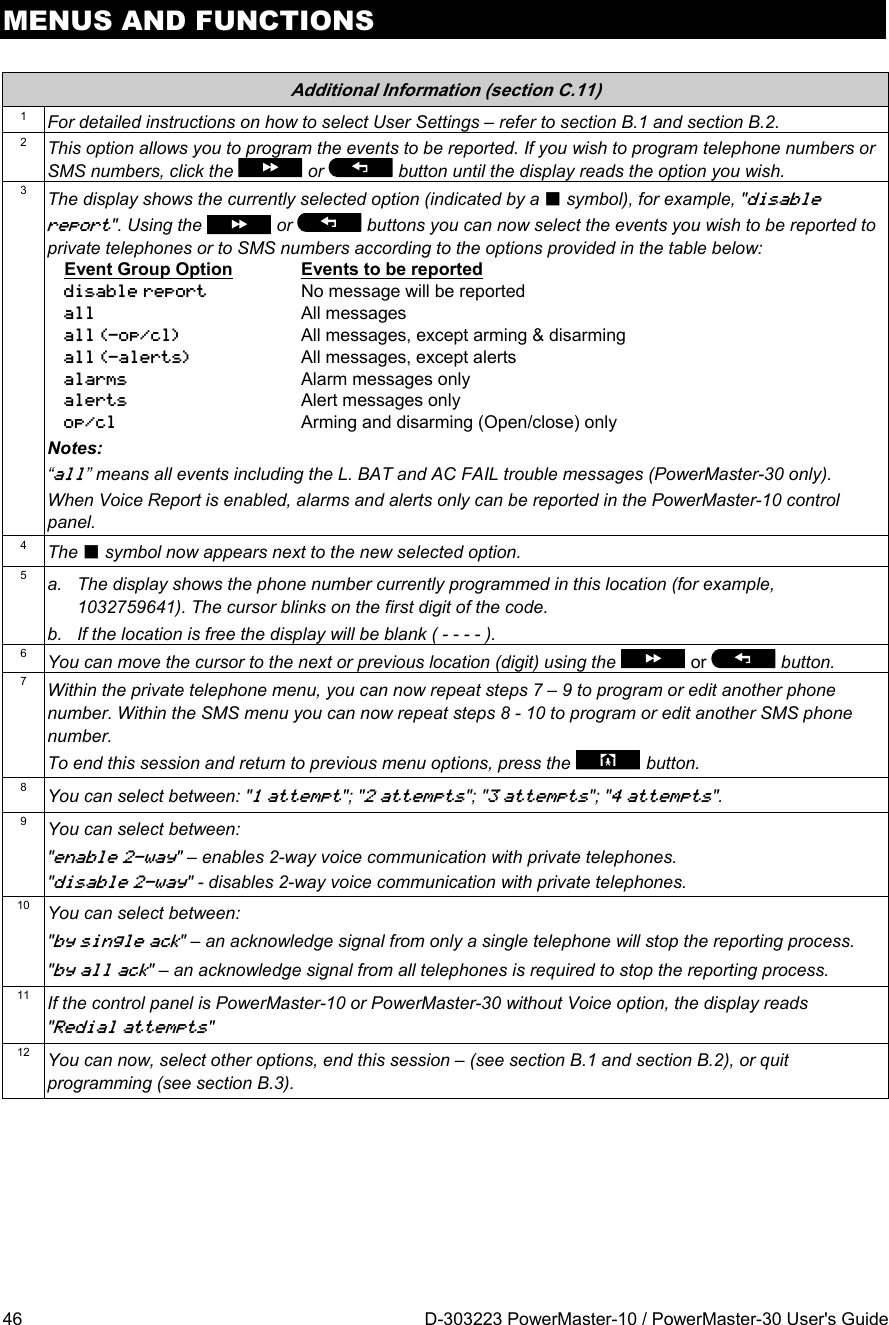
![MENUS AND FUNCTIONS D-303223 PowerMaster-10 / PowerMaster-30 User's Guide 43 C.11 Programming Private Phone and SMS Reporting The PowerMaster-10 / PowerMaster-30 system can be programmed to send various event notification messages such as alarm, arming or trouble events, to 4 private telephone subscribers by audible signal and if a GSM option is installed, also to 4 SMS telephone numbers. These reports can be programmed either instead of or in addition to the reports transmitted to the monitoring company. Further details about the event notification by telephone and by SMS are provided in Chapter 7. Event Reporting and Control by Telephone and SMS. You can also determine the number of times the private telephone number is dialed and whether a single acknowledge signal will stop the reporting process or an acknowledge signal from each telephone will be required before the current event is considered reported. Here you can program: The specific events you wish the system to report. The 1st, 2nd, 3rd, and 4th private telephone and SMS numbers for reporting alarm and other event messages to private subscribers. The number of redial attempts, two-way voice communication, and whether to use a single acknowledge signal or an acknowledge signal from each telephone before the current event is considered reported. Carefully read the section titled "Additional Information" according to the indicated references1 etc – see table at end of this section. VOICE REPORT A. To Program Events to be Reported by private telephone 1. Enter the USER SETTINGS menu and select the [PRIVATE REPORT] option and press the button to confirm. 1 2. The display will read [VOICE REPORT] which is the first option used to enable Private Reporting, to determine which events will be reported and to program private telephone numbers. To enter this option press . 3. When the display reads [REPORTED EVENTS] press . 2 The display shows the currently selected option. 4. or Click the or button until the display reads the event group you wish to be reported via private phones, for example, [alarms]. 3 5. When you are satisfied with the setting, press to confirm. ☺ Return to step 3 A "Happy Tune" ☺ sounds. The display confirms the set events to be reported, and returns to step 3. 4, 12 B. To Program a Private Phone 6. or Click the or button until the display reads the desired Telephone No. you wish to program or edit, for example, "2nd private tel#", and press to confirm. 7. Refers to PowerMaster-30 with voice option only REPORTED EVENTS REPORTED EVENTS alarms alarms VOICE REPORT 2nd private tel# disable report PRIVATE REPORT](https://usermanual.wiki/Visonic/PMASTER20G2.manual/User-Guide-1540038-Page-43.png)
![MENUS AND FUNCTIONS 44 D-303223 PowerMaster-10 / PowerMaster-30 User's Guide 8. To program or edit the phone number, at the blinking cursor position enter the phone number, for example, “8032759333”, using the numerical keypad. 5, 6 9. When done, press to confirm. ☺ Return to step 7 A "Happy Tune" ☺ sounds, the display confirms the telephone number and returns to step 7. 7, 12 C. To Program the Number of Redial Attempts 10. or Click the or button until the display reads [Redial attempts] and press to confirm. 11. The display shows the currently selected option. 12. or Click the or button until the display reads the desired number of redial attempts, for example, "4 attempts". 8 13. When you are satisfied with the setting, press to confirm. ☺ Return to step 11 A "Happy Tune" ☺ sounds. The display confirms the set number of redial attempts and returns to step 11. 4, 12 D. To Program two-way voice communication 14. or Click the or button until the display reads [Voice<- ->private] and press to confirm. 15. The display shows the currently selected option. 16. or Click the or button until the display reads the desired voice communication method, for example, "disable two-way". 9 17. When you are satisfied with the setting, press to confirm. 4 ☺ Return to step 15 A "Happy Tune" ☺ sounds. The display confirms the desired two-way voice communication method and returns to step 15. 4, 12 E. To Program the Acknowledge Method 18. or Click the or button until the display reads [Tel. acknowledge] and press to confirm. 11 Refers to PowerMaster-30 with voice option only disable two-way disable two-way Redial attempts enable two-way Voice<- ->private Voice<- ->private 4 attempts 2nd private tel# 80327593334 attempts 3 attempts Redial attempts 032759333](https://usermanual.wiki/Visonic/PMASTER20G2.manual/User-Guide-1540038-Page-44.png)
![MENUS AND FUNCTIONS D-303223 PowerMaster-10 / PowerMaster-30 User's Guide 45 19. The display shows the currently selected option. 20. or Click the or button until the display reads the desired acknowledge method, for example, "by all ack". 10 21. ☺ Return to step 19 A "Happy Tune" ☺ sounds. The display confirms the set acknowledge method and returns to step 19. 4, 12 SMS REPORT A. To Program Events to be Reported by SMS 1. Enter the USER SETTINGS menu and select the [PRIVATE REPORT] option and press the button to confirm. 1 2. When the display reads [VOICE REPORTS] press . 3. The display will read [SMS REPORT] which is the second option used to enable the Private Reporting, to determine which events will be reported via SMS and to program SMS telephone numbers. To enter this option press . 4. When the display reads [REPORTED EVENTS] press . The display shows the currently selected option. 3 5. or Click the or button until the display reads the event group you wish to be reported via SMS, for example, [all -alerts]. 4 6. When you are satisfied with the setting, press to confirm. ☺ Return to step 4 A "Happy Tune" ☺ sounds. The display confirms the set events to be reported, and returns to step 4. 4, 12 B. To Program SMS Telephone Numbers 7. or Click the or button until the display reads the desired SMS phone number you wish to program or edit, for example, "2nd SMS tel#", and press to confirm. 8. 9. To program or edit the phone number, at the blinking cursor position enter the SMS phone number, for example, “5080168593”, using the numerical keypad. 5, 6 10. When done, press to confirm. ☺ Return to step 8 A "Happy Tune" ☺ sounds, the display confirms the SMS phone number and returns to step 8. 7, 12 REPORTED EVENTS SMS REPORT 8032759333 REPORTED EVENTS alarms alarms VOICE REPORT 080168593 2nd SMS tel# disable report PRIVATE REPORT all ack by all ack by single ack Tel. acknowledge](https://usermanual.wiki/Visonic/PMASTER20G2.manual/User-Guide-1540038-Page-45.png)
![MENUS AND FUNCTIONS D-303223 PowerMaster-10 / PowerMaster-30 User's Guide 47 C.12 Enabling / Disabling the Squawk Option The PowerMaster-10 / PowerMaster-30 system (and its wireless sirens) can be set to produce a short "Squawk" of audible feedback to assist you when you use your keyfob to arm (1 beep) and disarm (2 beeps) the PowerMaster-10 / PowerMaster-30 system (operates in a similar manner to a car alarm). Here you can enable / disable the Squawk. Carefully read the section titled "Additional Information" according to the indicated references1 etc – see table at end of this section. 1. Enter the USER SETTINGS menu, select the [SQUAWK] option and press the button to confirm. 1 The display shows the currently selected setting. 2 2. or Click the or button until the display reads the desired setting, for example, "Squawk OFF" and press the button to confirm. 3. ☺ Return to step 1 A "Happy Tune" ☺ sounds. The display confirms the saved setting, then returns to the User Setting menu, step 1. 3, 4 Additional Information (section C.12) 1 For detailed instructions on how to select User Settings – refer to section B.1 and section B.2. 2 a. The display shows the currently selected setting (indicated by a symbol), for example, "Squawk ON". b. You can now enable (ON) or disable (OFF) the Squawk option using the or button. 3 The symbol now appears next to the new selected option. 4 You can now select another option in the User Setting menu (see section B.1 and section B.2), or quit programming (see section B.3). Squawk OFF Squawk ON SQUAWK OFF SQUAWK](https://usermanual.wiki/Visonic/PMASTER20G2.manual/User-Guide-1540038-Page-47.png)
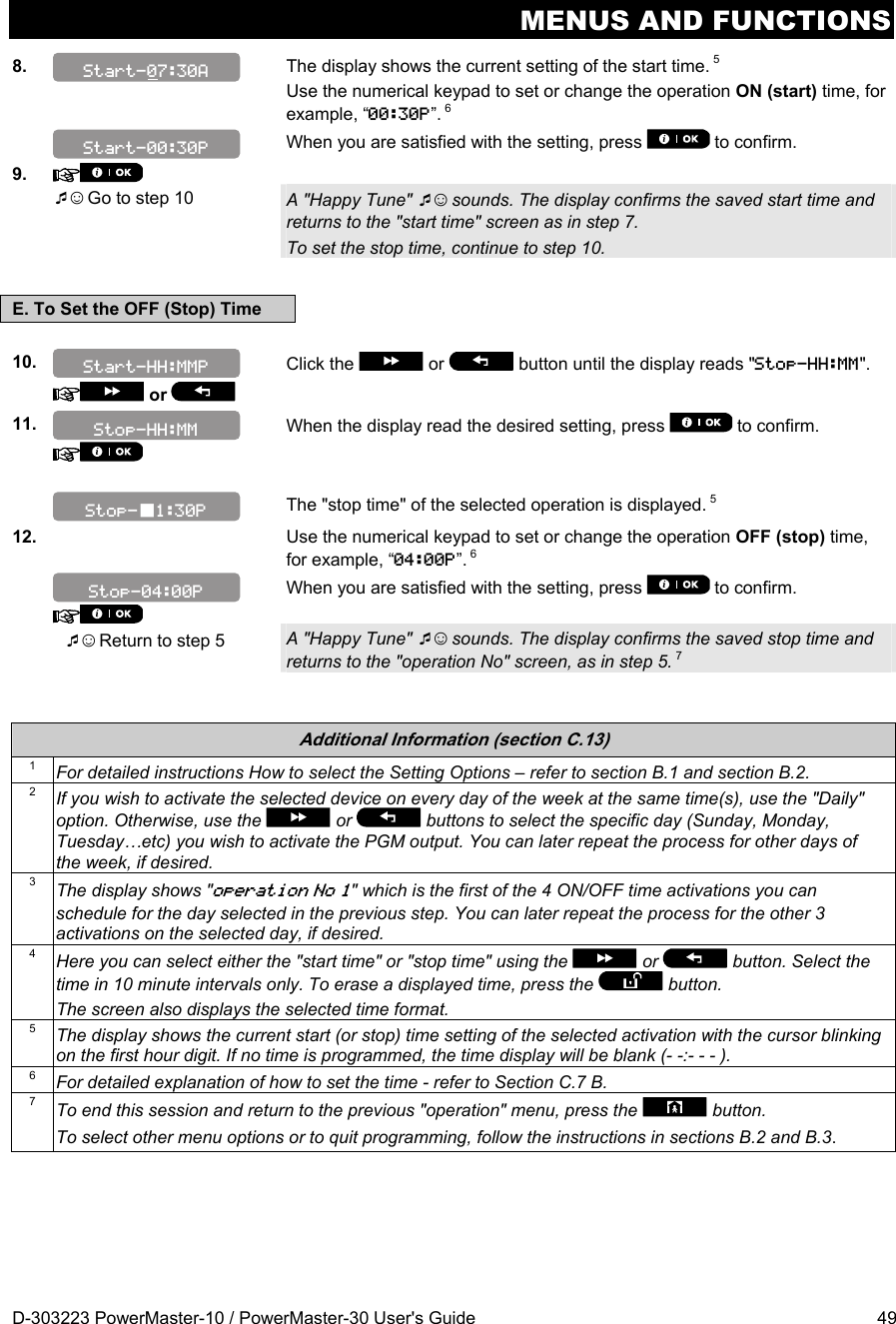
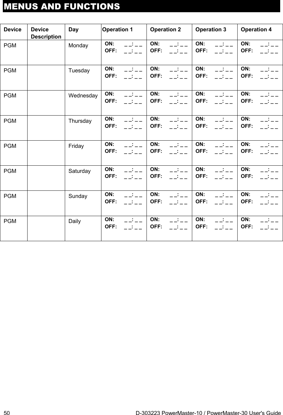
![MENUS AND FUNCTIONS 48 D-303223 PowerMaster-10 / PowerMaster-30 User's Guide C.13 Programming the Scheduler The PowerMaster-10 / PowerMaster-30 system includes a PGM output that can be used to open and close an electrically-controlled gate, or to control a preferred electrical device via keyfobs (refer to "Using keyfob transmitters" in Chapter 2) or according to a programmable weekly time schedule. Here you can schedule the PGM output for up to 4 different ON/OFF time activations per any desired day or days of the week. In addition, you can schedule a "Daily" schedule that applies to every day of the week. It is recommended to complete the Scheduler table (placed at the end of this section) before programming the Scheduler. Carefully read the section titled "Additional Information" according to the indicated references1 etc – see table at end of this section. A. To Select the Device No. 1. Enter the USER SETTINGS menu, select the [SCHEDULER] option and press to confirm. 1 2. When the display reads [PGM], press . B. To Set the Day 2 The 1st day of the scheduler is displayed. 3. or Click the or button until the display reads the day you wish to schedule or "Daily", for example, "Tuesday". 2 4. When the "day" you wish to schedule appears on the display, press to confirm. C. To Select the Activation No. 3 The 1st operation (PGM output activation) of the scheduler is displayed. 3 5. or Click the or button until the display reads the operation you wish to schedule, for example, "operation No 3". 6. When the "operation No." you wish to schedule appears on the display, press to confirm. D. To Set the ON (Start) Time 4 7. The "start time" screen is shown on the display. 4 To set the start time of the selected operation, press the button. PGM SCHEDULER Start-HH:MM operation No 3 operation No 1 Sunday Tuesday](https://usermanual.wiki/Visonic/PMASTER20G2.manual/User-Guide-1540038-Page-48.png)
![MENUS AND FUNCTIONS D-303223 PowerMaster-10 / PowerMaster-30 User's Guide 51 C.14 Enabling / Disabling Voice Option The system allows you to enable or disable Status-dependent, pre-recorded verbal messages that are heard over the built-in loudspeaker. Here you can enable / disable the Voice Option. Carefully read the section titled "Additional Information" according to the indicated references1 etc – see table at end of this section. 1. Enter the USER SETTINGS menu, select the [VOICE OPTION] option and press the button to confirm. 1 2. The display shows the currently selected setting. 2 or Click the or button until the display reads the desired setting, for example, "disable prompts" and press to confirm. 3 3. ☺ Return to step 1 A "Happy Tune" ☺ sounds. The display confirms the saved setting, then returns to step 1. 4, 5 Additional Information (section C.14) 1 For detailed instructions on how to select the Setting Options – refer to section B.1 and section B.2. 2 a. The display shows the currently selected setting (indicated by a symbol), for example, "enable prompts". b. You can now enable (voice prompts) or disable (no voice prompts) the voice option using the or button. 3 The symbol now appears next to the newly selected option. 4 You can now select another option in the User Setting menu (see section B.1 and section B.2), or quit programming (see section B.3). 5 If you have selected "enable prompts", make sure that the voice prompts can be heard over the loudspeaker by pressing the key on the control panel keypad. Refers to PowerMaster-30 with voice option only disable prompts enable prompts VOICE OPTION](https://usermanual.wiki/Visonic/PMASTER20G2.manual/User-Guide-1540038-Page-51.png)
![EVENT REPORTING & CONTROL BY TELEPHONE AND SMS 52 D-303223 PowerMaster-10 / PowerMaster-30 User's Guide 7. Event Reporting and Control by Telephone and SMS Event notifications by Telephone The PowerMaster-10 / PowerMaster-30 can be programmed for selective notification of event messages to private telephone subscribers – See Chapter – 6, C.11 Programming Private Phone and SMS Reporting. In case of alarm the following voice signal will be sent to private telephones upon event reporting: * FIRE: ON - ON - ON - pause.... (- - - - - - ......). ** BURGLAR: ON continuously ( ...) *** EMERGENCY: 2-tone siren; like an ambulance. To stop the alarm notification – press the "2" key on your telephone keyboard. The alarm sound will stop immediately. The called party must acknowledge the message (as explained later on). However, if there is no response the message will be repeated as many times as possible within a 45-second time limit. When the 45 seconds are up, the PowerMaster-10 / PowerMaster-30 will disengage the line and call the next private telephone number on its list. The called party must acknowledge the message by pressing the "2" key on the telephone keypad. As a result, the PowerMaster-10 / PowerMaster-30 may continue to notify the next programmed telephone number, or if so programmed, consider the event as reported - See Chapter – 4C.10. Event notifications by SMS The PowerMaster-10 / PowerMaster-30 system when equipped with a GSM unit can be programmed to send SMS event notification messages to 4 pre-selected telephone numbers - See Chapter – 4C.10. The messages can be tagged with a "House ID" name, for example, "JOHN'S HOME", see Remote Control by SMS section, command no. 9. Example of the reported SMS messages: JOHN’S HOME **AWAY** JOHN’S HOME **DISARM** JOHN’S HOUSE POWERMASTER-10 / POWERMASTER-30: LOW BATTERY GARAGE: LOW BATTERY JOHN’S HOUSE STATUS MESSAGE 01 (Event list is displayed) Note: Status messages can be sent only to a calling telephone whose identity number is not blocked by the user! Remote Control by Telephone The PowerMaster-10 / PowerMaster-30 allows you to initiate calls from your private telephone to the PowerMaster-10 / PowerMaster-30 control panel via PSTN (landline) or GSM and to perform a variety of arming commands remotely using your telephone's keypad. To connect to the PowerMaster-10 / PowerMaster-30 via PSTN: 1. Dial the PowerMaster-10 / PowerMaster-30 PSTN tel. No. 2. Wait for 2-4 rings then hang up. 1 3. Wait 12-30 sec. 4. Redial PowerMaster-10 / PowerMaster-30 tel. No. (Sound will be heard for 10 sec.). 5. [*] (to stop the sound) 6. [User code], [#] 2 7. [Desired command, see next table] 3](https://usermanual.wiki/Visonic/PMASTER20G2.manual/User-Guide-1540038-Page-52.png)
![EVENT REPORTING & CONTROL BY TELEPHONE AND SMS D-303223 PowerMaster-10 / PowerMaster-30 User's Guide 53 To connect to the PowerMaster-10 / PowerMaster-30 via GSM: 1. Dial the PowerMaster-10 / PowerMaster-30 GSM tel. No. 2. Wait for 2-4 rings then hang up. 1 3. Wait 12-30 sec. 4. Redial PowerMaster-10 / PowerMaster-30 GSM tel. No. 5. [User code], [#] 2 6. [Desired command, see next table] 3 Notes: (1) Alternative to steps 2 – 4: The PowerMaster-10 / PowerMaster-30 responds in a similar way if you just dial once and wait until you hear telephone rings (in USA, for example, 11 rings). (2) Entering of user code is required once only. (3) If you wait more that 50 seconds (may change according to setup / use) without keying a command, the PowerMaster-10 / PowerMaster-30 will disconnect the line. B. Executable Commands Command Single Partition Keying Sequence / PowerMaster-10 All Partitions Keying Sequence (PowerMaster-30) Notes 1 Disarming [][1][#] [][0][partition][1][#] 2 Arming Home [][2][#] [][0][partition][2][#] 3 Arming Home-Instant [][2][1][#] [][0][partition][2][1][#] 4 Arming Away [][3][#] [][0][partition][3][#] 5 Arming Away-Instant [][3][1][#] [][0][partition][3][1][#] 6 Arming Away-Latchkey [][4][#] [][0][partition][4][#] 7 Arming Away-Instant-Latchkey [][4][1][#] [][0][partition][4][1][#] 8 Review status of specific partition (Voice version only) [][0][partition][9][#] Not applicable to PowerMaster-10. Operates on ALL permitted partition(s). 9 Activating PGM output [][5][0] [0][1][#] [][5][device No.][1] [#] Not applicable to PowerMaster-10 10 Deactivating PGM output [][5][0] [0][0][#] [][5][device No.][0] [#] Not applicable to PowerMaster-10 11 Two-way voice communication (Voice version only) (see sub-par. C) [][7][#] [][7][#] Not applicable to PowerMaster-10 12 Recorded message playback [][8][1] [#] [][8][1] [#] Not applicable to PowerMaster-10 13 Recorded message start record [][8][2] [#] [][8][2] [#] Not applicable to PowerMaster-10 14 Recorded message stop record [][8][3] [#] [][8][3] [#] Not applicable to PowerMaster-10 15 Recorded message erase message [][8][4] [#] [][8][4] [#] Not applicable to PowerMaster-10 16 Investigating system status (Voice version only) [][9][#] [][9][#] Not applicable to PowerMaster-10](https://usermanual.wiki/Visonic/PMASTER20G2.manual/User-Guide-1540038-Page-53.png)
![EVENT REPORTING & CONTROL BY TELEPHONE AND SMS 54 D-303223 PowerMaster-10 / PowerMaster-30 User's Guide Command Single Partition Keying Sequence / PowerMaster-10 All Partitions Keying Sequence (PowerMaster-30) Notes 17 Quit (end communication) [][9][9][#] [][9][9][#] Remote Control by SMS PowerMaster-10 / PowerMaster-30 system with GSM unit can respond to SMS commands from any cellular telephone (a detailed SMS message sending process is described in the cellular telephone user’s guide). The various SMS commands are detailed in the following table. In this table, “<code>” means a 4-digit user code and simply means blank space (see Note). SMS Command List Command Individual Partition SMS Format / PowerMaster-10 All Partitions SMS format (PowerMaster-30) Notes 1 Arm AWAY “AWAY <code>” or “AW <code>” “P# AWAY <code>” or “P# AW <code>” 2 Arm AWAY instant “AWAY INST <code>” or “AWI <code>” “P# AWAY INST <code>” or “P# AWI <code>” 3 Arm AWAY Latchkey “LATCHKEY <code>” or “LK <code>” “P# LATCHKEY <code>” or “P# LK <code>” 4 Arm AWAY Latchkey instant “LATCHKEY INST <code>” or “LKI <code>” “P# LATCHKEY INST <code>” or “P# LKI <code>” 5 Arm HOME “HOME <code>” or “HM <code>” “P# HOME <code>” or “P# HM <code>” 6 Arm HOME instant “HOME INST <code>” or “HMI <code>” “P# HOME INST <code>” or “P# HMI <code>” 7 Disarm “DISARM <code>” or “DA <code>” “P# DISARM <code>” or “P# DA <code>” 8 Turn PGM on “PGM ON <code>” “P# PGM ON <code>” Not applicable to PowerMaster-10 9 Turn PGM off “PGM OFF <code>” “P# PGM OFF <code>” Not applicable to PowerMaster-10 10 Define custom house identity (see note) “HOUSE NAME <code> <house ID>” or “HN <code> <house ID>” “P# HOUSE NAME <code> <house ID>” or “P# HN <code> <house ID>” House ID includes up to 16 characters, for example, JOHN'S HOUSE 11 Query system status “STATUS <code>” or “ST <code>” “P# STATUS <code>” Or “P# ST <code>” Note: The PowerMaster-10 / PowerMaster-30 may react with a delay to received SMS messages if a GPRS session is in progress at the same time.](https://usermanual.wiki/Visonic/PMASTER20G2.manual/User-Guide-1540038-Page-54.png)
![TESTING THE SYSTEM 56 D-303223 PowerMaster-10 / PowerMaster-30 User's Guide 9. Testing the System Periodic Test The components of your security system are designed to be maintenance-free as much as possible. Nevertheless, it is mandatory to test the system at least once a week and after an alarm event to verify that all system sirens, detectors, keyfobs, keypads and other peripherals function properly. Proceed as described in this section and if there is any problem, notify your installer at once. The test is performed in three parts: Siren Test: Each siren of the system is automatically activated for 3 seconds (outdoor sirens with low volume). Temperature Sensor Test: When Temperature Sensors are enrolled in the system, the control panel displays the temperature of each zone in Celsius or Fahrenheit. Other Device Test: Each of the other devices in the system is activated by the user and the display indicates which devices were not yet tested. The "it's me" indication helps to identify the untested devices if necessary. A counter also indicates the number of devices that remain untested. Carefully read the section titled "Additional Information" according to the indicated references1 etc – see table at end of this section. A. To Enter the Periodic Test Menu 1. Make sure the system is disarmed and then press the button repeatedly until the display reads "PERIODIC TEST" and press to confirm. 1 2. The screen will now prompt you to enter your user code. 2 3. CODE Enter your User Code. 2 3 ☺ Go to step 4 B. To Test the Sirens 4. The display now reads [SIRENS TEST]. 5. To initiate the siren test press . Immediately after pressing , all 4 LED's on the panel should light (LED test). 4 The display now reads [SIREN N], where "N" indicates the zone location assigned to the siren that is currently being tested. 5 First the panel siren sounds for 3 seconds after which the PowerMaster-10 / PowerMaster-30 system will automatically repeat the procedure for the next siren enrolled in the system until all sirens are tested. 6 You should listen to the sirens sounds and make sure that all sirens sound. 6. or When all the sirens have been tested, the display reads [SIREN TESTS END]. Press the or the button to confirm the test and then move to the next step for zone temperature display. C. To Display the Temperature 7. The display now reads [TEMPERATURE TEST]. 8. To display the temperature of zones on the control panel, press . 7 TEMPERATURE TEST SIRENS TESTS END SIREN N SIRENS TEST ENTER CODE: PERIODIC TEST READY 00:00](https://usermanual.wiki/Visonic/PMASTER20G2.manual/User-Guide-1540038-Page-56.png)
![TESTING THE SYSTEM D-303223 PowerMaster-10 / PowerMaster-30 User's Guide 57 The control panel reads the temperature of each zone. The display alternates between the temperature, the sensor number and the sensor location. 8 Repeatedly click the button to review the temperature of each zone (by Temperature Sensor). 9. or When the temperature of all zones has been reviewed, the display reads [DEVICE TESTS END]. Press the or the button to confirm the test and then move to the next step to test the other devices. D. To Test all other Devices The display now reads [TEST ALL DEVICES]. 10. To enter the devices test procedure press . 11. The display now reads [NOT TESTED NNN]. NNN indicates the number of enrolled devices in the control panel that have not been tested yet. This number automatically drops one count for every tested device. To initiate the devices test press . The display shows the 1st device in the list of untested devices. The display alternates between the device number, the device type (e.g. magnetic contact ,keyfob, keypad, etc.), and the device location. The test is performed by activating each device as explained in the table below. 9 12. Click to scroll through the list of all untested devices. 10 13. When all devices have been activated, the display reads [DEVICE TESTS END] followed by [READY 00:00]. Guest room Z01:Temp. Sensor DEVICE TESTS END Z01 24.5C FRONT DOOR Z01 CONTACT Z01 NOT ACTIVE READY 00:00 DEVICE TESTS END NOT ACTIVE NNN TEST ALL DEVICES](https://usermanual.wiki/Visonic/PMASTER20G2.manual/User-Guide-1540038-Page-57.png)
![TESTING THE SYSTEM 58 D-303223 PowerMaster-10 / PowerMaster-30 User's Guide Additional Information (Periodic Test) 1 Display shown in disarm state when all zones are secured (00:00 or other digits show present time). 2 If you have not already changed your personal code number, use the default setting – 1111. 3 If the INSTALLER CODE is used to enter the Periodic Test instead of the USER CODE, the devices LED will also provide the link quality indication – see PowerMaster-10 / PowerMaster-30 Installer Manual. 4 To skip the SIRENS TEST and select the other devices TEST, press . 5 If the panel's display reads "SIREN P", this indicates that the control panel's siren is currently being tested. 6 The Periodic test can be performed on a maximum of three sirens including one internal siren. Outdoor sirens are activated with low volume. 7 If no temperature sensor is enrolled in the system, the display reads "NO EXISTING DEV.". 8 The displayed temperature can be in Celsius or Fahrenheit according to the programmed settings of the Temperature Sensor. 9 How to activate system devices during the "Periodic Test". Make sure the LED on the device lights when activated, as follows: Contact sensor: Open or close the door or window protected by the contact.Motion sensors: Perform a "walk test" of the detector as explained in the detector's datasheet. Smoke sensors: Perform a "Diagnostic test" as explained in the detector's datasheet. Keyfob: Activate any of the keyfob buttons. Keypads: Perform a disarm or arm routine or press any other key that activates the LED. Repeater: Follow the "Diagnostic Tests" described in the repeater's datasheet. Other devices: In general, follow the "Diagnostic Tests" described in the device's datasheet or activate any of its functions. 10 a. Three seconds after the device is displayed, the device LED blinks continuously to assist you to identify ("it's me"). b. To end the session, press the button until the display reads [<OK> TO EXIT] then press .](https://usermanual.wiki/Visonic/PMASTER20G2.manual/User-Guide-1540038-Page-58.png)
![MAINTENANCE 60 D-303223 PowerMaster-10 / PowerMaster-30 User's Guide Reading the Event Log To read the event log, proceed as follows: 1. 2. CODE When the PowerMaster-10 / PowerMaster-30 display reads [ENTER CODE: _], enter the current master user code. The "Happy Tune" will sound and the PowerMaster-10 / PowerMaster-30 display will read [LIST OF EVENTS]. (see Important Note!) 3. Click the button. The latest event will be shown. The event is displayed in two parts, for example, "Z13 alarm" then "09/02/10 3:37 P". The two displays will be shown alternately until clicking again to move to the next event or until the event log times out (4 minutes). 4. Click the button as many times as necessary to read all the required data. Important Note! Entering an incorrect code 5 times in a row will initiate a 30-second penalty lockout of the keypad. Attention: The system will not allow you to erase the event log. Only the installer is authorized to view and perform this function. Exiting the Event Log 1. or Click the or button from anywhere within the event log. The PowerMaster-10 / PowerMaster-30 display will read [<OK> TO EXIT]. 2. Click the button. The system reverts to the normal operating mode. READY 00:00 <OK> TO EXIT 09/02/10 3:37 P Z13 alarm LIST OF EVENTS ENTER CODE: _ READY 00:00](https://usermanual.wiki/Visonic/PMASTER20G2.manual/User-Guide-1540038-Page-60.png)