Visonic PMASTER20G2 Control panel of security, fire and safety system User Manual
Visonic Ltd. Control panel of security, fire and safety system Users Manual
UserManual.wiki
>
Visonic
>
PMASTER20G2 User Manual
>
Users Manual
Contents
1.
manual
2.
Users Manual
Users Manual
Navigation menu
Upload a User Manual
Namespaces
Wiki Guide
HTML
PDF
Info
Views
User Manual
Discussion / Help
Navigation
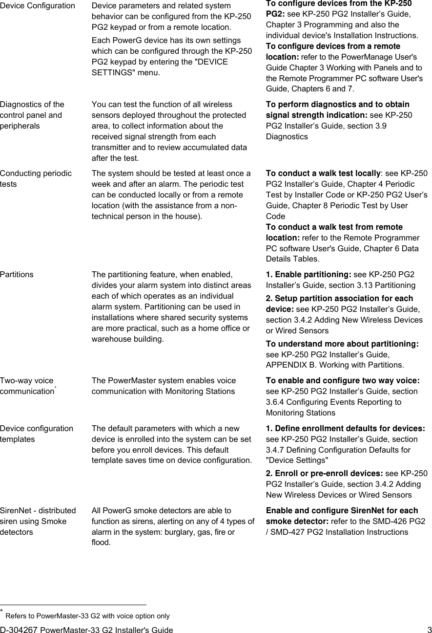

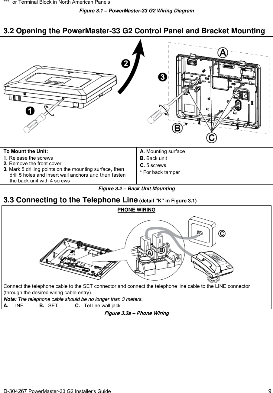
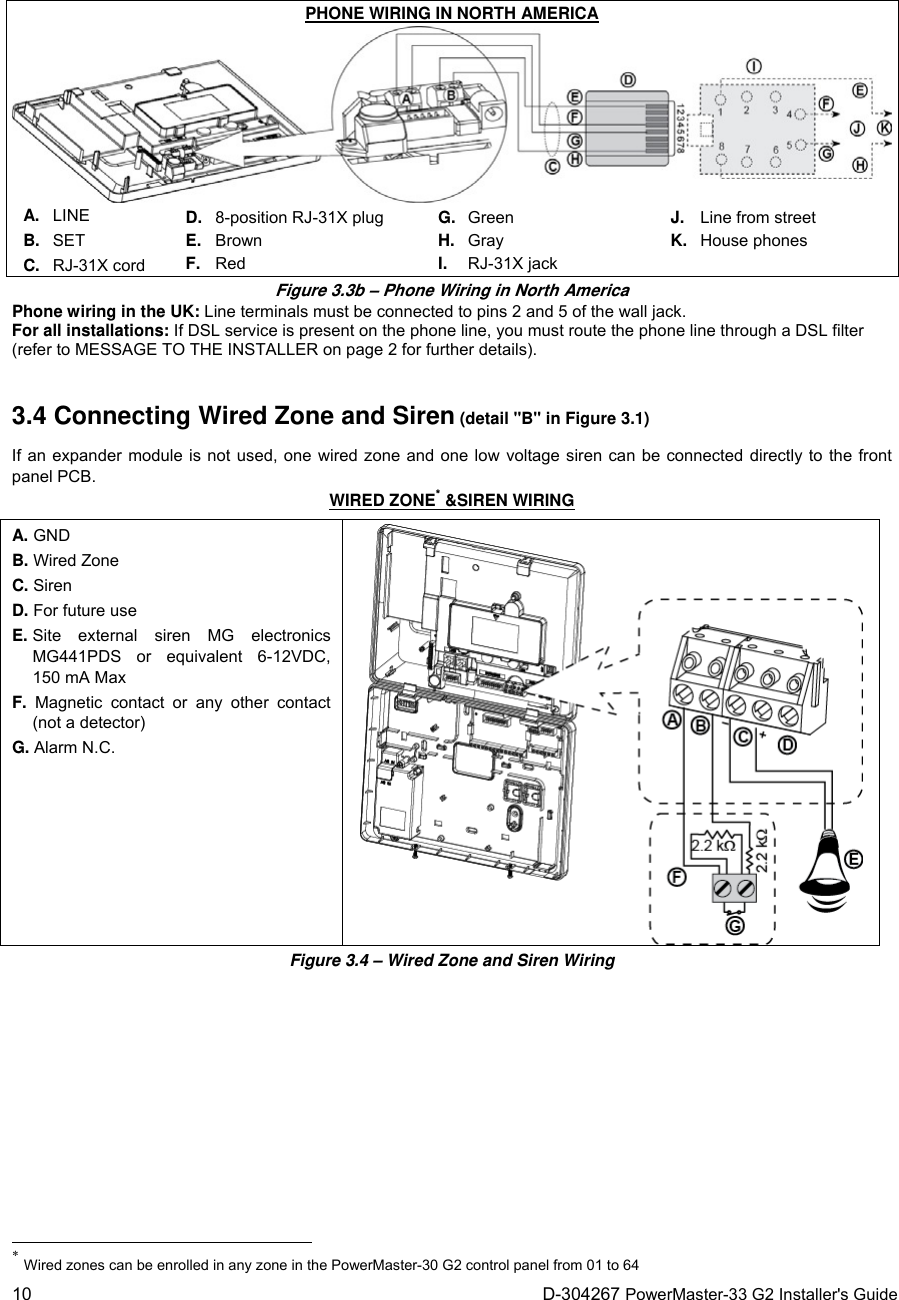
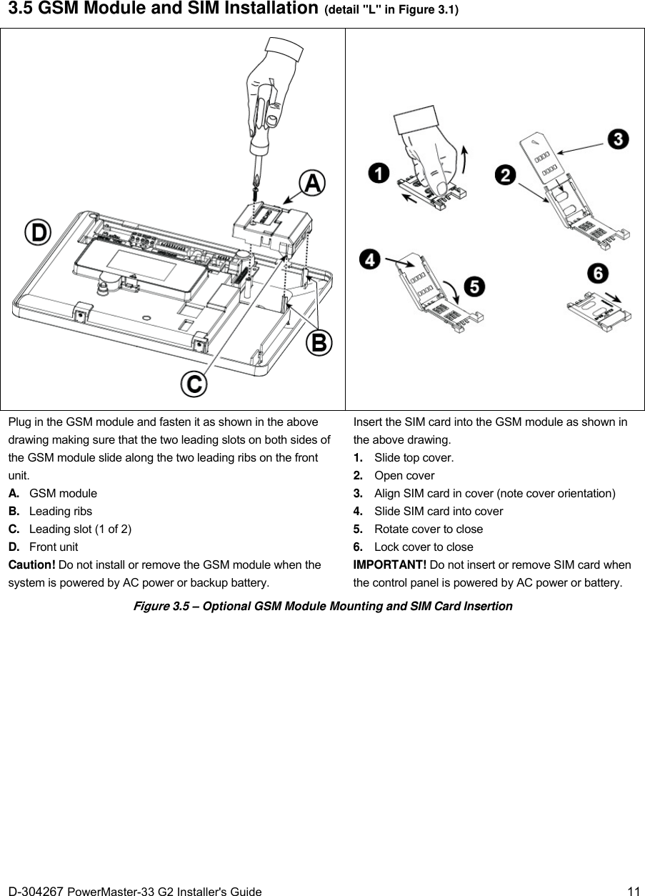
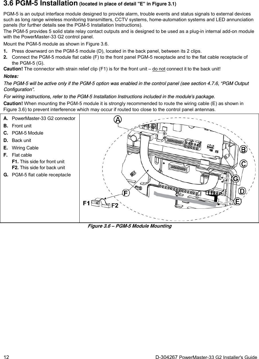
![Quick User Guide to Main Alarm Control Operations by KP-250 PG2 Keypad The Quick Start Guide is intended for the user of the system. Please remove this detachable sheet and hand it to the user. Arming and Disarming the System Step Operation User Actions Key & Keypad Response Optional 1 Press the Partition Selection button and then select a PARTITION (if Partition is enabled) followed by any combination of The selected key blinks. 2 Arm AWAY + [ ] or enter code The selected key and the "Present Prox Tag" LED () begin to blink and prompt you to present your Tag or enter your user code. The keypad's LED blinks red once to indicate transmission of the arming command to the control panel. The LED and the buzzer then indicate the control panel's response – refer to the KP-250 PG2 User’s Guide, Chapter 4 “System Status and Indications”. Arm HOME + [] or enter code Disarm (OFF) + [ ] or enter code Optional Quick arm AWAY (If Quick Arm is enabled) Quick arm HOME (If Quick Arm is enabled) Forced arming AWAY (system not ready) + [ ] or enter code to silence the “protest” buzzer Forced arming HOME (system not ready) + [] or enter code to silence the “protest” buzzer Optional 3 INSTANT (After arming HOME/AWAY) LATCHKEY Note: The factory default master user code is 1111. The code is not required if quick arming has been permitted by the installer. Change the factory default code to a secret code without delay (refer to the KP-250 PG2 User’s Guide, Chapter 6, section B.4). Initiating Alarms Alarms Actions NotesEmergency alarm ( 2 sec.) When pressing the Fire or Emergency icons, the KP-250 PG2 starts beeping. After pressing the button for approx. 2 seconds, the KP-250 PG2 sends the command. Fire alarm ( 2 sec.) Panic alarm ( 2 sec.)](https://usermanual.wiki/Visonic/PMASTER20G2.Users-Manual/User-Guide-2407945-Page-24.png)