Visonic PMASTER20G2 Control panel of security, fire and safety system User Manual
Visonic Ltd. Control panel of security, fire and safety system Users Manual
Visonic >
Contents
- 1. manual
- 2. Users Manual
Users Manual
D-304267 PowerMaster-33 G2 Installer's Guide 1
PowerMaster-33 G2
Version 18
Installer’s Guide
Table of Contents
1. INTRODUCTION ................................................... 2
1.1 System Features ............................................ 2
2. CHOOSING THE INSTALLATION LOCATION ... 6
3. POWERMASTER-33 G2 INSTALLATION ........... 7
3.1 PowerMaster-33 G2 Wiring Diagram............ 7
3.2 Opening the PowerMaster-33 G2 Control
Panel and Bracket Mounting ............................ 98
3.3 Connecting to the Telephone Line (detail
"K" in Figure 3.1) ............................................... 98
3.4 Connecting Wired Zone and Siren (detail
"B" in Figure 3.1) ............................................. 109
3.5 GSM Module and SIM Installation (detail
"L" in Figure 3.1) ............................................ 1110
3.6 PGM-5 Installation (located in place of
detail "E" in Figure 3.1) ................................. 1211
3.7 Installing the PowerLink3 ....................... 1312
3.8 Optional Expander Module (detail "I" in
Figure 3.1) ....................................................... 1413
3.9 Connecting Power to the Control Panel 1615
3.9.1 Battery Insertion .............................. 1716
3.9.2 Connect AC Power to the Unit ........ 1716
3.10 Closing the PowerMaster-33 G2 Control
Panel ............................................................... 1817
4. VISUAL INDICATIONS, FIRST KEYPAD
ENROLLMENT AND USING PROX TAG ......... 1918
4.1 PowerMaster-33 LED Indications .......... 1918
4.2 Enrollment of the First KP-250 PG2 Keypad
........................................................................ 1918
4.3 Using the Prox Tag ................................. 2019
5. MAINTENANCE ............................................. 2019
5.1 Dismounting the Control Panel ............. 2019
5.2 Replacing the Backup Battery ............... 2019
5.3 Fuse Replacement .................................. 2019
5.4 Replacing/Relocating Detectors ............ 2019
5.5 Annual System Check ............................ 2019
APPENDIX A. Specifications ........................... 2120
A1. Functional ............................................... 2120
A2. Wireless ................................................... 2120
A3. Electrical.................................................. 2120
A4. Communication ...................................... 2221
A5. Physical Properties ................................ 2221
A6. Peripherals and Accessory Devices .... 2221
APPENDIX B. Compliance with Standards ...... 2322
Quick User Guide to Main Alarm Control
Operations by KP-250 PG2 Keypad ................ 2423

2 D-304267
PowerMaster-33 G2 Installer's Guide
1. INTRODUCTION
PowerMaster is a PowerG-enabled professional all-in-one wireless security, fire and safety system supporting advanced
applications and Visonic's PowerG™ Two-Way, Time Division Multiple Access (TDMA) and Frequency Hopping Spread
Spectrum (FHSS) wireless technology. This offers unmatched wireless robustness, superior range and long battery life; a
perfect and user friendly solution for both monitoring service providers and professional installers.
The system consists of the PowerMaster-33 G2 control panel that does not include a built-in keypad and that operates
in conjunction with a wireless keypad display device (KP-250 PG2). The control panel accommodates all control
circuitry and operation software for a programmable 64-zone alarm system, while the keypad display unit enables the
installer and the user to enter their commands and provides visual and audible feedback.
This manual refers to PowerMaster-33 G2 v18 and above. The most updated manuals can be downloaded from the
Visonic Web site http://www.visonic.com.
Note: "Pmaster" is used as an abbreviation for "PowerMaster".
The system is supplied with 3 instruction manuals:
PowerMaster-33 G2 Installer's Guide (this manual) – for use of system installer during system installation.
KP-250 PG2 Installer’s Guide -– for use of system installer during KP-250 PG2 installation and PowerMaster-33 G2
configuration.
KP-250 PG2 User’s Guide -– also for use of system installer during system installation and configuration, but also for
the master user of the system, once installation is completed. Hand over this manual to the master user of the system.
1.1 System Features
The following table lists the PowerMaster features with a description of each feature and how to use it.
Feature Description How to configure and use
Visual Alarm
Verification
The PowerMaster when used with Next CAM
PG2 PIR-camera detector and GPRS
communication is able to provide the
Monitoring Station with clips captured in
alarm situations. The system sends the clips
to the Monitoring Station automatically for
burglary alarms and, depending on setup,
also for fire and personal emergency alarms.
1. Setup GPRS communication: see GSM
Module Installation section 3.5)
2. Configure camera settings: refer to the
Next CAM PG2 Installation Instructions
3. Enable fire and personal alarm
verification: see KP-250 PG2 Installer’s
Guide, section 3.6.6 Configuring Motion
Cameras for Video Alarm Verification
On demand clips from
cameras
The PowerMaster can provide images from
the Next CAM PG2 by demand from a
remote PowerManage server. Pictures are
taken based on a command from the
monitoring station. To protect customers'
privacy, the system can be customized to
enable the "On Demand View" only during
specific system modes (i.e. Disarm, Home &
Away) and also to a specific time window
following an alarm event.
1. Setup the On demand feature: see
KP-250 PG2 Installer’s Guide, section 3.6.6
Configuring Motion Cameras for Video Alarm
Verification
2. To request and view images: refer to the
PowerManage User's Guide, Chapter 5
Viewing and Handling Events
Easy Enrollment PowerG devices are enrolled from the control
panel. "Pre-enrollment" can also be
performed by entering the PowerG device ID
number and then activating the device in the
vicinity of the panel.
To enroll or pre-enroll devices: see
KP-250 PG2 Installer’s Guide, section 3.4.2
Adding New Wireless Devices or Wired
Sensors

D-304267 PowerMaster-33 G2 Installer's Guide 3
Device Configuration Device parameters and related system
behavior can be configured from the KP-250
PG2 keypad or from a remote location.
Each PowerG device has its own settings
which can be configured through the KP-250
PG2 keypad by entering the "DEVICE
SETTINGS" menu.
To configure devices from the KP-250
PG2: see KP-250 PG2 Installer’s Guide,
Chapter 3 Programming and also the
individual device's Installation Instructions.
To configure devices from a remote
location: refer to the PowerManage User's
Guide Chapter 3 Working with Panels and to
the Remote Programmer PC software User's
Guide, Chapters 6 and 7.
Diagnostics of the
control panel and
peripherals
You can test the function of all wireless
sensors deployed throughout the protected
area, to collect information about the
received signal strength from each
transmitter and to review accumulated data
after the test.
To perform diagnostics and to obtain
signal strength indication: see KP-250
PG2 Installer’s Guide, section 3.9
Diagnostics
Conducting periodic
tests
The system should be tested at least once a
week and after an alarm. The periodic test
can be conducted locally or from a remote
location (with the assistance from a non-
technical person in the house).
To conduct a walk test locally: see KP-250
PG2 Installer’s Guide, Chapter 4 Periodic
Test by Installer Code or KP-250 PG2 User’s
Guide, Chapter 8 Periodic Test by User
Code
To conduct a walk test from remote
location: refer to the Remote Programmer
PC software User's Guide, Chapter 6 Data
Details Tables.
Partitions The partitioning feature, when enabled,
divides your alarm system into distinct areas
each of which operates as an individual
alarm system. Partitioning can be used in
installations where shared security systems
are more practical, such as a home office or
warehouse building.
1. Enable partitioning: see KP-250 PG2
Installer’s Guide, section 3.13 Partitioning
2. Setup partition association for each
device: see KP-250 PG2 Installer’s Guide,
section 3.4.2 Adding New Wireless Devices
or Wired Sensors
To understand more about partitioning:
see KP-250 PG2 Installer’s Guide,
APPENDIX B. Working with Partitions.
Two-way voice
communication*
The PowerMaster system enables voice
communication with Monitoring Stations
To enable and configure two way voice:
see KP-250 PG2 Installer’s Guide, section
3.6.4 Configuring Events Reporting to
Monitoring Stations
Device configuration
templates
The default parameters with which a new
device is enrolled into the system can be set
before you enroll devices. This default
template saves time on device configuration.
1. Define enrollment defaults for devices:
see KP-250 PG2 Installer’s Guide, section
3.4.7 Defining Configuration Defaults for
"Device Settings"
2. Enroll or pre-enroll devices: see KP-250
PG2 Installer’s Guide, section 3.4.2 Adding
New Wireless Devices or Wired Sensors
SirenNet - distributed
siren using Smoke
detectors
All PowerG smoke detectors are able to
function as sirens, alerting on any of 4 types of
alarm in the system: burglary, gas, fire or
flood.
Enable and configure SirenNet for each
smoke detector: refer to the SMD-426 PG2
/ SMD-427 PG2 Installation Instructions
* Refers to PowerMaster-33 G2 with voice option only
4 D-304267
PowerMaster-33 G2 Installer's Guide
Integrated Siren built
into the panel
The control panel has a high-powered built-in
siren that sounds in case of alarm, enabled by
default.
To define whether or not the control
panel's siren will sound upon alarms: see
KP-250 PG2 Installer’s Guide, section 3.5.5
Configuring Sirens Functionality
Wired Siren outputs The control panel can operate a wired siren
and strobe devices
Install and connect wired siren: see
section 3.8 Optional Expander Module
Wired zones and
programmable
outputs (PGM)
The control panel can support wired detectors
and control automation devices with
programmable wired outputs.
1. Connect a wired zone or PGM device: see
section 3.4 Adding a Wired Zone and Siren.
2. Program the wired zone: see KP-250
PG2 Installer’s Guide, section 3.4.2 Adding
New Wireless Devices or Wired Sensors
3. Program PGM outputs behavior: see
KP-250 PG2 Installer’s Guide, section 3.7
PGM Output.
Reporting to Private
Users and/or
Monitoring Station by
telephone, SMS and
IP communication
The PowerMaster system can be
programmed to send notifications of alarm
and other events to 4 private telephone
subscribers by voice and also to 4 SMS
cellular phone numbers and to report these
events to the Monitoring Station by SMS,
PSTN or IP communication.
To configure notifications to Private
phones: see KP-250 PG2 User’s Guide,
Chapter 6, section B.12 Programming
Private Phone and SMS Reporting
To configure reporting to the Montioring
Station: see KP-250 PG2 Installer’s Guide,
section 3.6.4 Configuring Events Reporting
to Monitoring Stations
Quick installation with
link quality indication
With PowerG devices, there is no need to
consult the KP-250 PG2 keypad when
mounting a wireless device, because
PowerG devices include a built-in link quality
indicator. Choosing the mounting location is
a quick and easy process.
To choose the ideal location to mount a
wireless device, see Chapter 2 Choosing the
Installation Location.
Device Locator Helps you to easily identify the actual device
displayed on the KP-250 PG2 LCD display.
To read more on the Device Locator: see
KP-250 PG2 User’s Guide, Chapter 3,
Arming and Disarming the System
To use the device locator when bypassing
a zone or when clearing a bypassed zone:
see KP-250 PG2 User’s Guide, Chapter 6,
section B.1 Setting the Zone Bypass Scheme
To use the device locator when conducting
the periodic test: see KP-250 PG2 Installer’s
Guide, Chapter 4 Periodic Test by Installer
Code or KP-250 PG2 User’s Guide, Chapter 8
Periodic Test by User Code.
Guard key-safe PowerMaster is able to control a safe that
holds site keys that are accessible only to the
site's guard or Monitoring Station's guard in
the event of an alarm.
1. Connect the safe to the panel: see
section 3.8 Optional Expander Module
Mounting, Figure 3.8b
2. Configure the safe's zone type to
"Guard Zone": see KP-250 PG2 Installer’s
Guide, section 3.4.2 Adding New Wireless
Devices or Wired Sensors
3. Setup guard code: see KP-250 PG2
Installer’s Guide, section 3.3 Setting Installer
Codes
Arming key External system may control arming and
disarming of the PowerMaster system
Connect the external system output to the
panel: see section 3.8 Optional Expander
Module Mounting, Figure 3.8b
D-304267 PowerMaster-33 G2 Installer's Guide 5
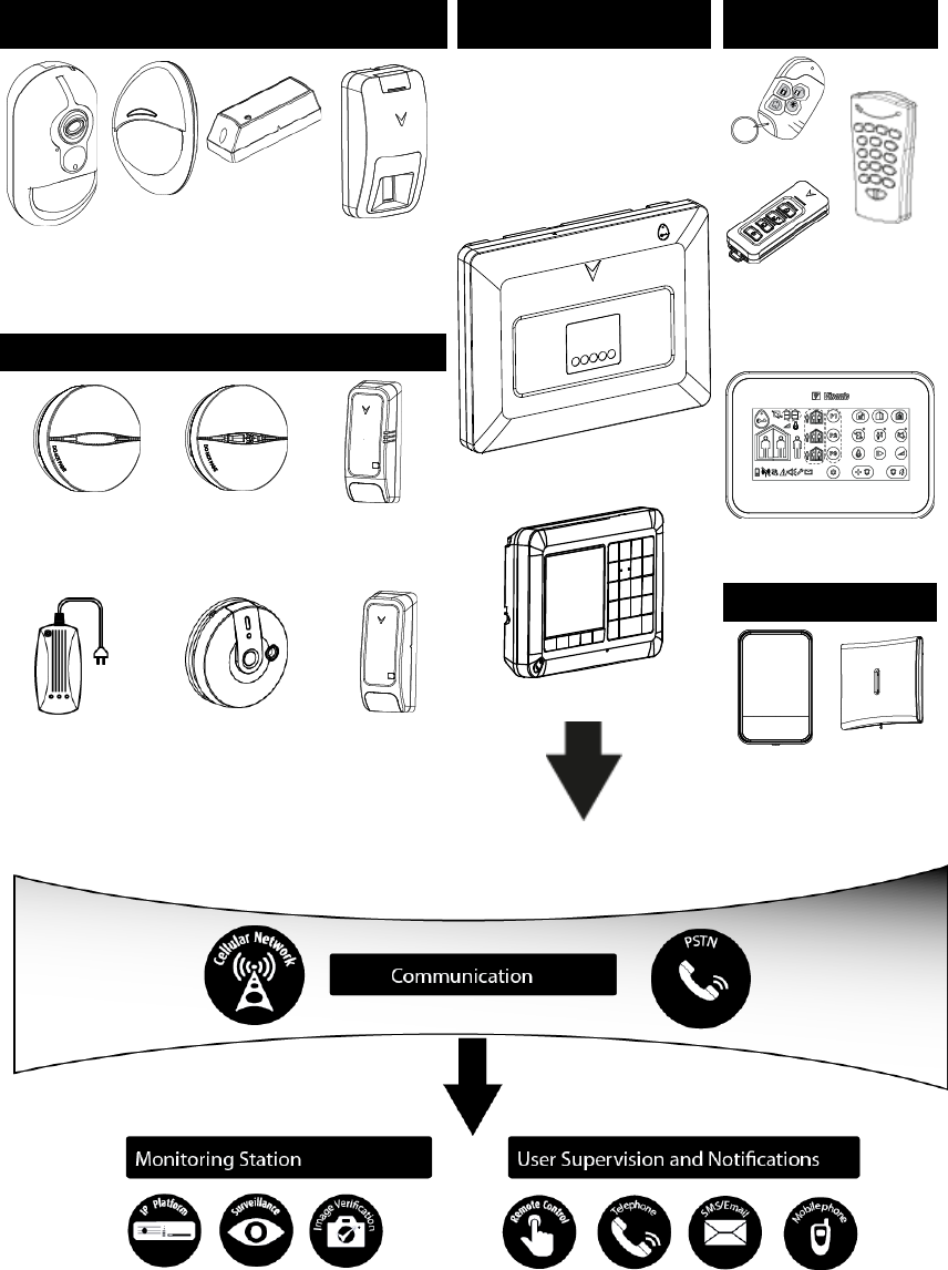
System Architecture:
Security Detectors and Transmitters Control Panel and Display
Keypad Keyfobs, Keypad and
Keyprox
Next CAM
PG2 Motion
Detector
with Camera
Next PG2
Motion
Detector
MC-302 PG2
Magnetic
Contact
TOWER-30AM
PG2
Mirror Detector
PowerMaster-33 G2
KP-250 PG2
KF-234 PG2
KF-235 PG2
Two-way
Keyfobs
KP-140 PG2
Two-way
Keypad
Safety Detectors
KP-160 PG2 Keyprox
SMD-426 PG2
Smoke Detector
SMD-427 PG2
Smoke & Heat
Detector
TMD-560 PG2
Temperature
Detector
GSD-441 PG2
Gas (Methane)
Detector
GSD-442 PG2
Carbon Monoxide (CO)
Detector
FLD-550 PG2
Flood
Detector
Sirens
SR-730 PG2
Outdoor
Siren
SR-720 PG2
Indoor Siren
6 D-304267
PowerMaster-33 G2 Installer's Guide
2. CHOOSING THE INSTALLATION LOCATION
To ensure the best possible mounting location of the PowerMaster control panel, the following points should be
observed:
The selected location should be approximately in the center of the installation site between all the transmitters,
preferably in a hidden location.
In close proximity to an AC source
In close proximity to a telephone line connection (if PSTN is used)
Where there is good cellular coverage, if GSM-350 PG2 is used
Far from sources of wireless interference, such as:
o Computers or other electronic devices, power conductors, cordless phones, light dimmers, etc.
o Large metal objects (such as metal doors or refrigerators)
Note: A distance of at least 1 meter (3 ft) is recommended.
When mounting wireless devices:
Make sure that the signal reception level for each device is either "Strong" or "Good", but not "Poor".
Wireless magnetic contacts should be installed in a vertical position and as high up the door or window as possible.
Wireless PIR detectors should be installed upright at the height specified in their Installation Instructions
Repeaters should be located high on the wall in mid-distance between the transmitters and the control panel.
WARNING! To comply with FCC and IC RF exposure compliance requirements, the control panel should be located at
a distance of at least 20 cm from all persons during normal operation. The antennas used for this product must not be
co-located or operated in conjunction with any other antenna or transmitter.
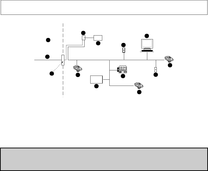
Customer Premises Equipment and Wiring
A
B
C
D
E
F
G
H
I
E
E
H
J
A. Network Service Provider's Facilities F. Alarm Dialing Equipment
B. Telephone Line G. Answering System
C. Network Demarcation Point H. Unused RJ-11 Jack
D. RJ-31X Jack I. Fax Machine
E. Telephone J. Computer
Note: The REN is used to determine the number of devices that may be connected to a telephone line. Excessive RENs on a telephone line
may result in the devices not ringing in response to an incoming call. In most but not all areas, the sum of RENs should not exceed five (5.0).
To be certain of the number of devices that may be connected to a line, as determined by the total RENs, contact the local telephone
company.
Connection to telephone company provided coin service is prohibited. Connection to party lines service is subject to state tariffs.
The installer should verify line seizure. Be aware of other phone line services such as DSL. If DSL service is present on the
phone line, you must install a filter. It is suggested to use the DSL alarm filter model Z-A431PJ31X manufactured by
Excelsus Technologies, or equivalent. This filter simply plugs into the RJ-31X jack and allows alarm reporting without
breaking the internet connection.
D-304267 PowerMaster-33 G2 Installer's Guide 7
3. POWERMASTER-33 G2 INSTALLATION
Required tool: Philips screwdriver #2.
PowerMaster-33 G2 mounting process is shown in Figures 3.1 - 3.10.
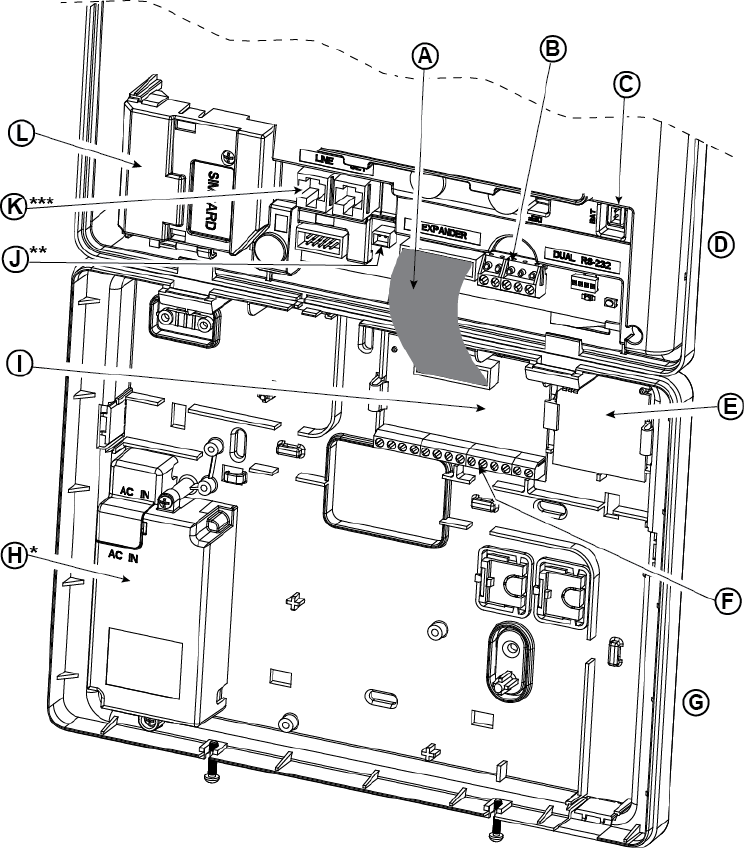
3.1 PowerMaster-33 G2 Wiring Diagram
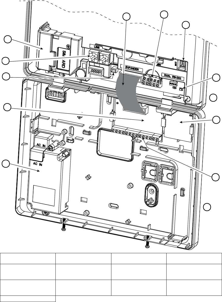
8 D-304267
PowerMaster-33 G2 Installer's Guide
I
E
G
H
J
K
*
M
**
AC
B
***
F
D
L
A. Expander Module Flat
Cable
B. Wired Zone / Special
Siren Terminal Block C. Battery Connector D. Front UnitEnroll 1st
Keypad button
E. PGM-5 ModuleFront Unit F. Expander Module Wiring
Terminal BlocksPGM-5
Module
G. Back Unit Expander
Module Wiring Terminal
Blocks
H. Power SupplyBack Unit
I. Expander ModulePower
Supply J. Power Connector
Expander Module K. Phone Wiring Connectors
Power Connector L. Phone Wiring
ConnectorsGSM-350
PG2
M. GSM-350 PG2
* or External Power Supply Unit
** or External Power Connector
D-304267 PowerMaster-33 G2 Installer's Guide 9
*** or Terminal Block in North American Panels
Figure 3.1 – PowerMaster-33 G2 Wiring Diagram
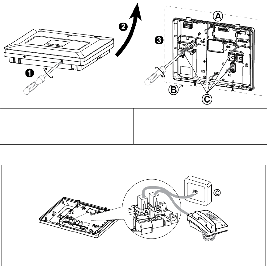
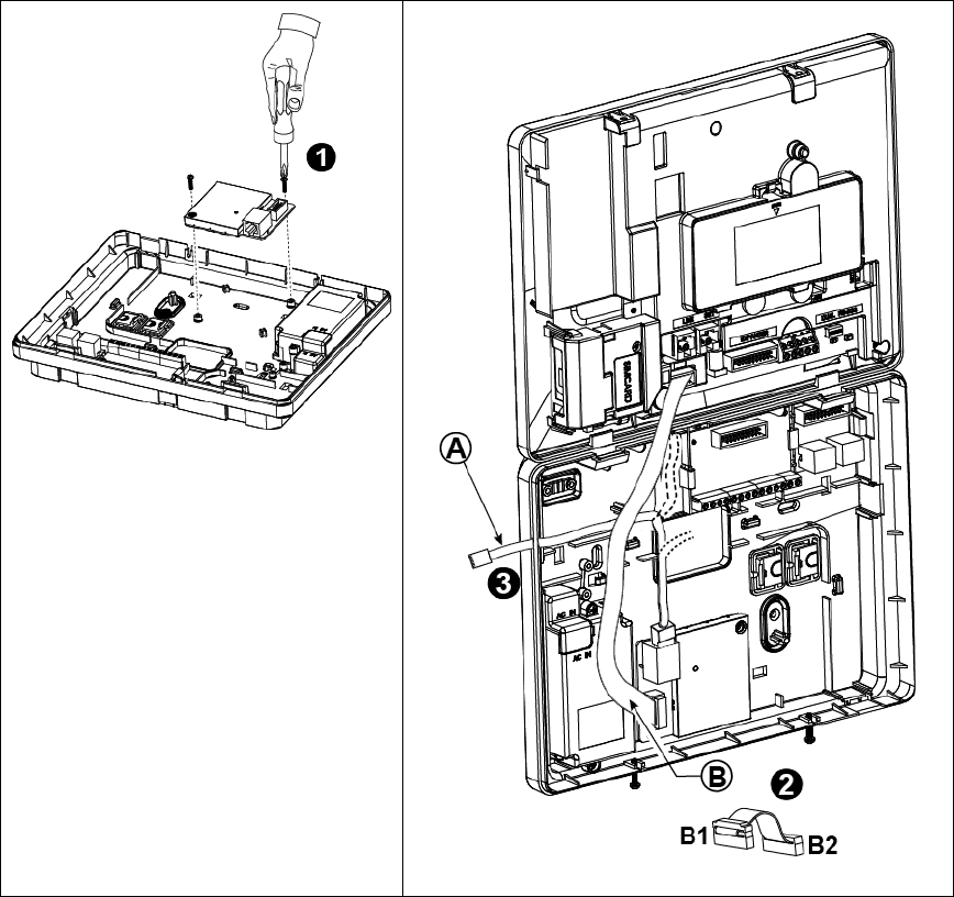
3.2 Opening the PowerMaster-33 G2 Control Panel and Bracket Mounting
To Mount the Unit:
1. Release the screws
2. Remove the front cover
3. Mark 5 drilling points on the mounting surface, then
drill 5 holes and insert wall anchors and then fasten
the back unit with 4 screws
A. Mounting surface
B. Back unit
C. 5 screws
* For back tamper
Figure 3.2 – Back Unit Mounting
3.3 Connecting to the Telephone Line (detail "K" in Figure 3.1)
PHONE WIRING
Connect the telephone cable to the SET connector and connect the telephone line cable to the LINE connector
(through the desired wiring cable entry).
Note: The telephone cable should be no longer than 3 meters.
A. LINE B. SET C. Tel line wall jack
Figure 3.3a – Phone Wiring
10 D-304267
PowerMaster-33 G2 Installer's Guide
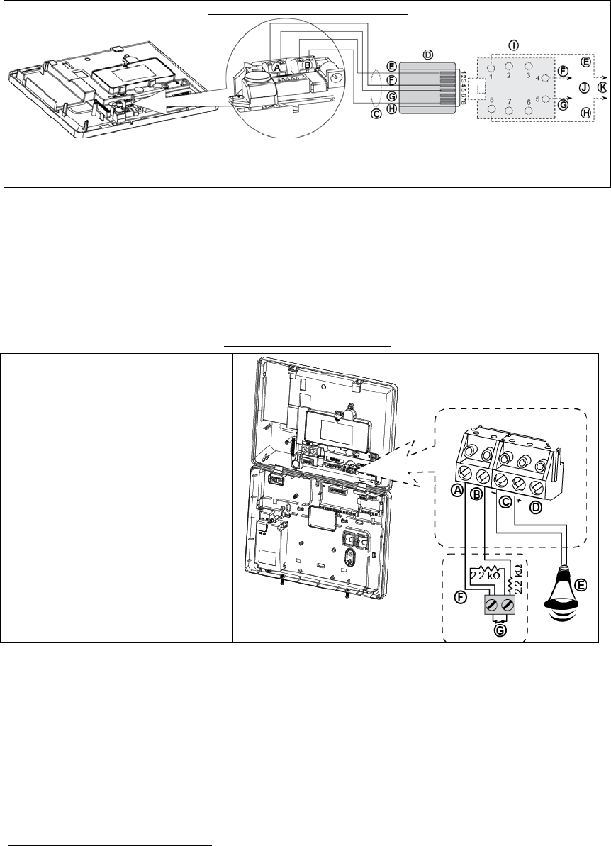
PHONE WIRING IN NORTH AMERICA
A. LINE
B. SET
C. RJ-31X cord
D. 8-position RJ-31X plug
E. Brown
F. Red
G. Green
H. Gray
I. RJ-31X jack
J. Line from street
K. House phones
Figure 3.3b – Phone Wiring in North America
Phone wiring in the UK: Line terminals must be connected to pins 2 and 5 of the wall jack.
For all installations: If DSL service is present on the phone line, you must route the phone line through a DSL filter
(refer to MESSAGE TO THE INSTALLER on page 2 for further details).
3.4 Connecting Wired Zone and Siren (detail "B" in Figure 3.1)
If an expander module is not used, one wired zone and one low voltage siren can be connected directly to the front
panel PCB.
WIRED ZONE* &SIREN WIRING
A. GND
B. Wired Zone
C. Siren
D. For future use
E. Site external siren MG electronics
MG441PDS or equivalent 6-12VDC,
150 mA Max
F. Magnetic contact or any other contact
(not a detector)
G. Alarm N.C.
Figure 3.4 – Wired Zone and Siren Wiring
* Wired zones can be enrolled in any zone in the PowerMaster-30 G2 control panel from 01 to 64
D-304267 PowerMaster-33 G2 Installer's Guide 11
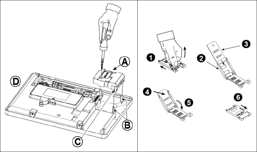
3.5 GSM Module and SIM Installation (detail "L" in Figure 3.1)
Plug in the GSM module and fasten it as shown in the above
drawing making sure that the two leading slots on both sides of
the GSM module slide along the two leading ribs on the front
unit.
A. GSM module
B. Leading ribs
C. Leading slot (1 of 2)
D. Front unit
Caution! Do not install or remove the GSM module when the
system is powered by AC power or backup battery.
Insert the SIM card into the GSM module as shown in
the above drawing.
1. Slide top cover.
2. Open cover
3. Align SIM card in cover (note cover orientation)
4. Slide SIM card into cover
5. Rotate cover to close
6. Lock cover to close
IMPORTANT! Do not insert or remove SIM card when
the control panel is powered by AC power or battery.
Figure
3.5 – Optional GSM Module Mounting and SIM Card Insertion
12 D-304267
PowerMaster-33 G2 Installer's Guide
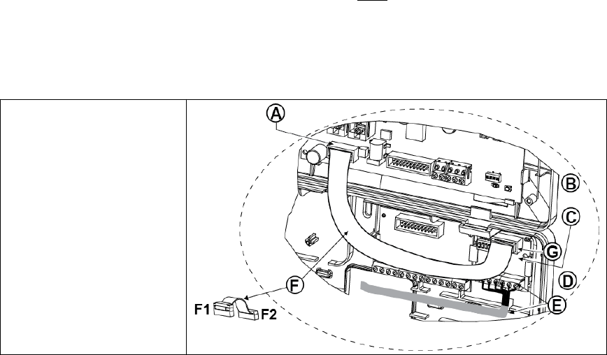
3.6 PGM-5 Installation (located in place of detail "E" in Figure 3.1)
PGM-5 is an output interface module designed to provide alarm, trouble events and status signals to external devices
such as long range wireless monitoring transmitters, CCTV systems, home-automation systems and LED annunciation
panels (for further details see the PGM-5 Installation Instructions).
The PGM-5 provides 5 solid state relay contact outputs and is designed to be used as a plug-in internal add-on module
with the PowerMaster-33 G2 control panel.
Mount the PGM-5 module as shown in Figure 3.6.
1. Press downward on the PGM-5 module (D), located in the back panel, between its 2 clips.
2. Connect the PGM-5 module flat cable (F) to the front panel PGM-5 receptacle and to the flat cable receptacle of
the PGM-5 (G).
Caution! The connector with strain relief clip (F1) is for the front unit – do not connect it to the back unit!
Notes:
The PGM-5 will be active only if the PGM-5 option was enabled in the control panel (see section 4.7.6, “PGM Output
Configuration”.
For wiring instructions, refer to the PGM-5 Installation Instructions included in the module's package.
Caution! When mounting the PGM-5 module it is strongly recommended to route the wiring cable (E) as shown in
Figure 3.6) to prevent interference which may occur if routed too close to the control panel antennas.
A. PowerMaster-33 G2 connector
B. Front unit
C. PGM-5 Module
D. Back unit
E. Wiring Cable
F. Flat cable
F1. This side for front unit
F2. This side for back unit
G. PGM-5 flat cable receptacle
Figure 3.6 – PGM-5 Module Mounting
D-304267 PowerMaster-33 G2 Installer's Guide 13
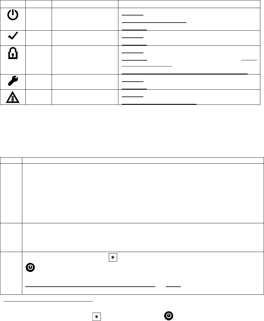
3.7 Installing the PowerLink3
The PowerLink3 is used to view and control the PowerMaster system over the Internet.
Perform the following instructions for the PowerLink3 installation.
Note: PowerLink3 operation is not backed up by
the control panel’s battery and it is shut down
during AC failure.
1. Mount the internal PowerLink3 into the back
unit and fasten it with 2 screws.
2. Connect the flat cable (B) from the front panel
to the PowerLink3, as follows: Connector B1
to the front panel; connector B2 to the
PowerLink3.
3. Connect the Cat-5 cable from the PowerLink3
to the home router.
Note: In order to prevent interference to the
antenna, do not route the Cat-5 cable through
the cable entry knockout on the right side of
the panel.
A. Cat-5 cable to home router
B. Flat cable
B1. This side for front unit
B2. This side for PowerLink3
Figure 3.7 – PowerLink3 Mounting
14 D-304267
PowerMaster-33 G2 Installer's Guide
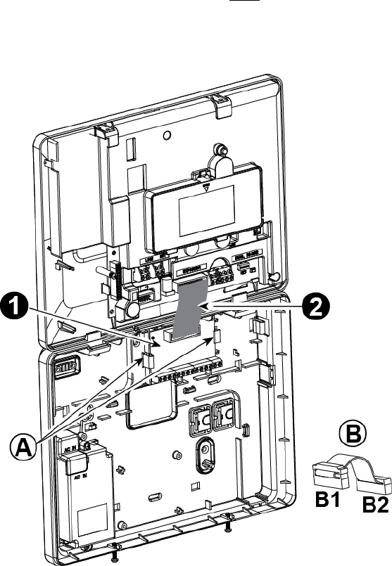
3.8 Optional Expander Module (detail "I" in Figure 3.1)
The Expander module is an optional module. If this optional module is used, the wired zone or special siren on the front
panel should not be used.
Mount the Expander module as shown in Figure 3.8a.
1. Press downward on the Expander module (located in the back panel) between its 2 clips.
2. Connect the Expander module flat cable to the front panel Expander receptacle.
Caution! The receptacle with strain relief clip is for the front unit – do not connect it to the back unit!
A. 2 clips
B. Flat cable with one strain relief clip
B1. This side for front unit
B2. This side for back unit
Figure 3.8a –Expander Module
D-304267 PowerMaster-33 G2 Installer's Guide 15
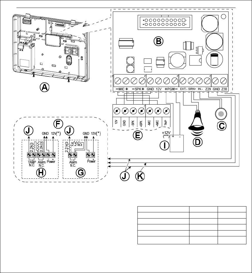
OPTIONAL EXPANDER MODULE, ZONES, SIRENS, AUDIO BOX AND WIRED DETECTORS WIRING
A. Back Unit
B. Expander
C. Internal siren or strobe 6-12 VDC,
150 mA Max.
D. External siren MG441PDS or similar siren 12 VDC
(nominal) 350 mA Max.
E. Voice box
F. Connect wired detectors as illustrated.
Note:
The wired detector should be installed at least 2
meters away from the control panel.
Regarding the two wired zones, the control panel
classifies the events according to the resistance it
measures as shown in the table below.
E.O.L or Arming Key Resistance
Range Zone Arming Key
0 kΩ
1.76 kΩ Tamper Tamper
1.76 kΩ
2.64 kΩ Normal Arm
2.64 kΩ
3.52 kΩ Tamper Tamper
3.52 kΩ
5.26 kΩ Alarm Disarm
5.26 kΩ ∞ Tamper Tamper
G. Detector without tamper switch or arming key
H. Detector with tamper switch or arming key's tamper
I. PGM device
J. Wired zone A or B
K. Ground (GND)
Figure 3.8b – Zone
and Siren Wiring
Notes for EXPANDER module wiring:
* Wired zone
terminals can be connected to a normally closed contact of a detector, switch (for example a Tamper
switch of any device), or a pushbutton, via a 2.2 K
resistor. The 12V terminal can be used to supply 12V (up to
36mA) to a detector (if necessary).
** The EXT terminal can be used to trigger an external siren.
The INT terminal can be programmed for an "internal siren" or "strobe" (see par. 4.7).
The 12V and "GND" terminals can be connected to a siren (for constant DC power supply).
*** The.12V supply to the PGM device is fused. Current is limited to 100 mA.
WARNING! When plugging terminals back into place, be sure to align them carefully with the pins on the PCB.
Misaligned or reverse insertion of terminals may damage internal PowerMaster-33 G2 circuits!
IMPORTANT! The terminals for internal and external sirens are DC outputs intended for 12V sirens. Connecting a
loudspeaker to any of these outputs will cause a short circuit and will damage the unit.
16 D-304267
PowerMaster-33 G2 Installer's Guide
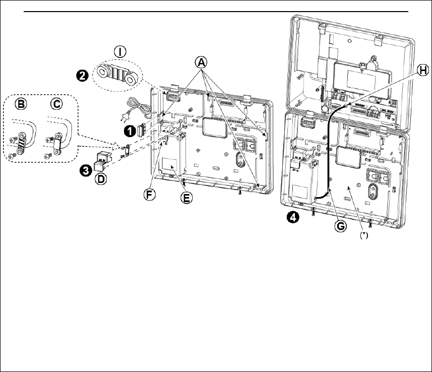
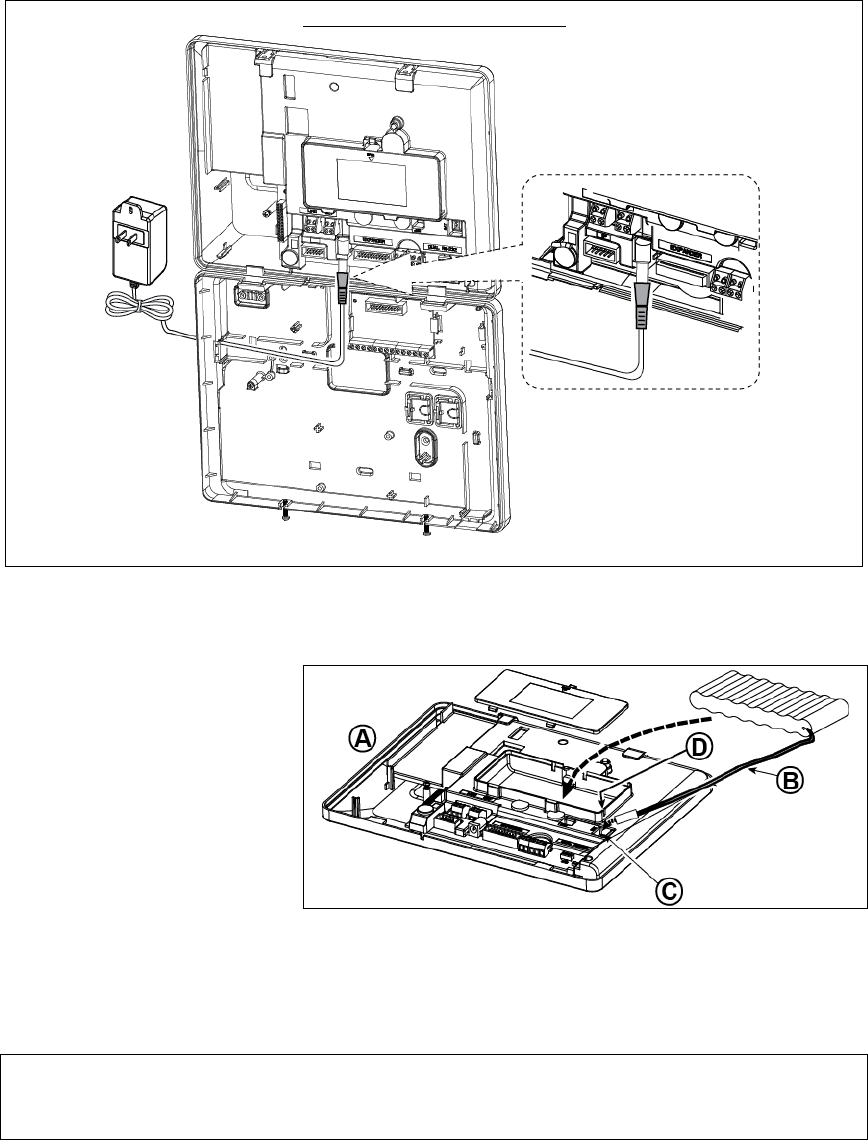
3.9 Connecting Power to the Control Panel
Note: This equipment should be installed in accordance with Chapter 2 of the National Fire Alarm Code, ANSI/NFPA 72.
Connect the power cable and close the control panel as shown in Figures 3.9a –3.10.
POWER CABLE CLAMP EXTRACTION AND POWER CONNECTION FOR INTERNAL POWER SUPPLY
Perform steps 1 & 2 on a workbench before mounting.
1. Thick cable entry: Pull out a desired wiring plastic
cap (1 of 4).
2. Extract cable clamp (I) for use in the next step.
3. Insert the power cable through the desired wiring
channel (A). Route it to the power supply unit (E) and
remove the safety cover (D). Connect the 2 wires of
the power cable to the power supply terminal block
(F) with a screwdriver. Fasten the screws tightly.
Fasten the power cable by its clamp (B or C) and
close the safety cover (D).
4. Connect the power supply output cable (G) to the
power connector (H) in the front panel.
A
. Optional wiring channels
B. For thin cable
C. For thick cable (reversed clamp)
D. Safety cover
E. Power supply unit
F. Power supply terminal block
G. Power supply output cable
H. Power connector
(*) Do not route wiring in this area, to enable proper
closure of the control panel.
I. Cable clamp.
Figure 3.9a – Power Cable Clamp Extraction and Power Connection for Internal Power Supply
D-304267 PowerMaster-33 G2 Installer's Guide 17
EXTERNAL POWER CONNECTION
Connect the power adaptor to the front panel power connector.
Figure 3.9b – External Power Connection
3.9.1 Battery Insertion
Open battery compartment cover.
Insert one 6-battery pack or 8-battery
pack and connect its connector as
shown in Figure 3.8c.
A. Front unit
B. Battery cable
C. Battery cable connector
D. Slot for battery cable
Figure 3.9c – Battery Insertion
3.9.2 Connect AC Power to the Unit
Connect power to the PowerMaster-33 G2 to mains power outlet (see Figures 3.8a and 3.8b).
Disregard any “trouble” indications pertaining to lack of battery or lack of telephone line connection.
For Europe Safety Compliance:
a. The model shall be installed according to the local electrical code.
b. The circuit breaker shall be readily accessible.
c. The rating of the external circuit breaker shall be 16A or less.

18 D-304267
PowerMaster-33 G2 Installer's Guide
3.10 Closing the PowerMaster-33 G2 Control Panel
Control panel final closure is shown below.
To Close the Control Panel:
1. Connect the flat cables, between front and back units, in their
respective connectors (up to 3, according to options).
2. Make sure that the "Power" indicator on the control panel lights
green.
3. Close the panel and fasten the 2 screws.
Figure 3.
10 - Final Closure
D-304267 PowerMaster-33 G2 Installer's Guide 19
4. VISUAL INDICATIONS, FIRST KEYPAD
ENROLLMENT AND USING PROX TAG
4.1 PowerMaster-33 LED Indications
The following table provides a detailed description of the LED indications on the PowerMaster-33 panel.
Color Definition LED Operation
Green Local Power indication STEADY: Indicates that system has mains power
BLINKING: Low battery state
NO LIGHT: AC failure
Green Ready / Not Ready
Indication
STEADY: All partitions are ready
NO LIGHT: Not Ready / at least one partition is Not Ready
Red System Arming State
Indication
STEADY: AWAY / At least one partition is AWAY
BLINKING: HOME / At least one partition is HOME and no
partitions are in AWAY
NO LIGHT: The system is presently in the disarmed state
Orange System Not Online
Indication
STEADY: System is unavailable (Sync/Updating/In-menu)
NO LIGHT: System is available
Orange System Trouble indication STEADY: System has trouble
NO LIGHT: No trouble – all is well
4.2 Enrollment of the First KP-250 PG2 Keypad
The PowerMaster-33 G2 is designed to operate wirelessly with the KP-250 PG2 keypad display device installed
anywhere within the protected premises.
The first keypad must always beis always enrolled as Keypad no. 1. If a keypad is already enrolled at Keypad no.1, the
keypad will be deleted and the LED will light to indicate this.
Step Action
1 Press the "Enroll 1st Keypad" button (located on the front unit of the PowerMaster-33 G2 control panel –
see Figure 3.1) on the PowerMaster-33 G2 control panel for 2 seconds. If no keypad exists in the first
location, the "Enroll 1st Keypad" LED on the PowerMaster-33 G2 blinks slowly for one 1 minute (go to step
3).
If a keypad already exists in the first location, the "Enroll 1st Keypad" LED on the PowerMaster-33 G2
control panel lights steady for 10 seconds (go to step 2).
Note: Pressing the "Enroll 1st Keypad" button takes the system out of any of the system modes,
programming modes, etc., and disarms the system menu mode (Installer Mode, User Settings and Periodic
Test).
2 If you still want to proceed (any keypad that was enrolled in keypad no. 01 is deleted from the system),
press the "Enroll 1st Keypad" button again within the timeout period (10 seconds). Any keypad that was
enrolled in keypad no. 01 is deleted from the system.
The "Enroll 1st Keypad" LED on the PowerMaster-33 G2 blinks slowly for 1 minute.
3 During this 1 minute period, hold the button on the KP-250 PG2 keypad for 2-55-7 seconds, until the
LED on the keypad lights bluered, and release*. The enrollment "Enroll 1st Keypad" LED on the
PowerMaster-33 G2 will indicate the result of the enrollment procedure.
PowerMaster-33 G2 "Enroll 1st Keypad" LED indication Result
Blinks fast for 5 sec. Successful enrollment of keypad
* If the KP-250 PG2 unit is battery-powered: first press any button on the KP-250 PG2 keypad momentarily to take the KP-250 PG2
keypad out of sleep mode and then hold the button for 5-7 seconds, until the LED on the keypad lights red, and release.
20 D-304267
PowerMaster-33 G2 Installer's Guide
Lights steadily for 5 sec. Wrong device type
4 Upon completion of the enrolling procedure, the keypad is ready for immediate use even if the system is
currently in the Armed state.
Note: If the keypad was previously enrolled at a different keypad no., it will be automatically relocated
automatically to Keypad no. 1. However, all of the configured parameters will be lost and the keypad will
revert to the default parameters.
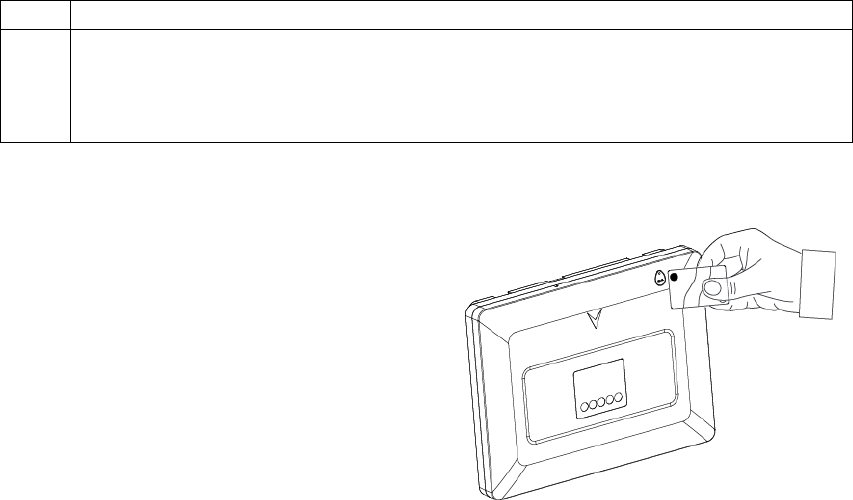
4.3 Using the Prox Tag
Proximity tags enable authorized people to enter
restricted areas. Presenting a valid proximity tag to the
tag reader (as shown in the drawing) while the system is
armed causes the system to disarm. Presenting a valid
proximity tag to the tag reader while the system is
disarmed causes the system to be armed in AWAY
(optional HOME) mode. To enroll / delete proximity tags,
refer to the KP-250 PG2 User’s Guide.
Notes:
1. Use of the Proximity tags is optional.
2. Proximity tags are not compatible for use when partition
is enabled.
5. MAINTENANCE
5.1 Dismounting the Control Panel
A. Remove the screw that fastens the front unit to the back unit, see Figure 3.2.
B. Remove the 4 screws that fasten the back unit to the mounting surface - Figure 3.2 - and remove the control panel.
5.2 Replacing the Backup Battery
Replacement and first-time insertion of battery pack is similar, see Figure 3.9c.
With a fresh battery pack, correct insertion and tightened battery compartment lid, the TROUBLE indicator on the kp-
250 PG2 keypad should extinguish. However, the “MEMORY” message will now blink in the display (caused by the
“tamper” alarm you triggered when opening the battery compartment lid). Clear it by arming the system and
immediately disarming.
5.3 Fuse Replacement
The PowerMaster-33 G2 has two internal fuses that has automatic reset. Therefore, there is no need to replace the
fuses.
When over current condition occurs, the fuse cuts off the circuit current. Upon fault current being removed for several
seconds, the fuse is automatically reset and allows current flow through the circuit again.
5.4 Replacing/Relocating Detectors
Whenever maintenance work involves replacement or re-location of detectors, always perform a full diagnostic test
according to the KP-250 PG2 User’s Guide, section 12.9.
Remember! A "poor" signal is not acceptable.
5.5 Annual System Check
Note: The PowerMaster system must be checked by a qualified technician at least once every three (3) years
(preferably every year).
The annual system check is designed to ensure proper operation of the alarm system by performing the following checks:
Periodic test
Arm/disarm function
No trouble messages are displayed on control panel
The clock displays the correct time
Reporting: generating an event to be transmitted to the Monitoring Station and to the user.

D-304267 PowerMaster-33 G2 Installer's Guide 21
APPENDIX A. Specifications
A1. Functional
Zones Number Up to 64 wireless zones, (including 2 hard-wired inputs).
Hard-wired Zone Requirements 2.2 kE.O.L. resistance (max. resistance of wires 220
Maximum Loop Current 1.5 mA
Maximum Loop Voltage 3.3 V
Loop Shorted 0 – 1.47 V (0 – 1.770 Ω)
Loop Normal 1.47 – 1.8 V and 2.02 – 2.3 V
Loop Open 2.3 – 3.3 V (5.06 - ∞ Ω)
Installer and User Codes
1 master installer (9999 by default)*
1 installer (8888 by default)*
1 master user, no. 1 (1111 by default)
Users nos. 2 - 48
* Codes must not be identical
Control Facilities - Integral keypad, wireless keyfobs and keypads
- SMS commands via optional GSM/GPRS module.
- Remote control by telephone.
Arming Modes AWAY, HOME, AWAY-INSTANT, HOME-INSTANT, LATCHKEY, FORCED, BYPASS.
Alarm Types Silent, personal panic/emergency, burglary, gas, fire and flood.
Siren Signals Continuous (intrusion / 24 hours / panic); triple pulse – short pause - triple pulse... (fire);
four pulses – long pause – four pulses... (gas);
long pulse – long pause – long pulse... (flood).
Siren (bell) Timeout Programmable (4 min. by default)
Internal Sounder Output At least 85 dBA at 10 ft (3 m)
Supervision Programmable time frame for inactivity alert
Special Functions - Chime zones
- Diagnostic test and event log.
- Local and Remote Programming over Telephone, GSM /GPRS connections.
- Calling for help by using an emergency transmitter.
- Tracking inactivity of elderly, physically handicapped and infirm people.
- Message center (recording and playback)
- Two-way voice communication
Data Retrieval Alarm memory, trouble, event log
Real Time Clock (RTC) The control panel keeps and displays time and date. This feature is also used for the log
file b
y
providin
g
the date and time of each event
Battery Test Once every 10 seconds
A2. Wireless
RF Network PowerG – 2-way synchronized Frequency Hopping (TDMA / FHSS)
Frequency bands (MHz) 433 – 434 868 - 869 912 - 919
Hopping frequencies 8 4 50
Region Worldwide Europe North America and
selected countries
Encryption AES-128
A3. Electrical
External AC/AC adaptor NA
External AC/DC adaptor External (wall-mounted) switching power supply 100VAC to 240VAC, 50/60 Hz, 0.5A
/ 12.5 VDC, 1.2A
Internal AC/DC Internal switching power supply:
Input: 100-240VAC, 0.5A
Output: 12.5 VDC, 1.6A.
Current Drain Approx. 260 mA standb
y
at the beginning (power ON) and then goes down to 60 mA,
1400 mA max. cur
r
ent drain durin
g
alarm.
Low Battery Threshold 7.2 V (6-cell battery pack)
9.6 V (8-cell battery pack)
Backup Battery Pack Backup Battery Options:
Backup
period
Maximum external devices current (1)
1300 mAh
6 Battery Pack (2)
1800 mAh
8-BatteryPack (3)
2200 mAh 8-Battery
Pack (4)
4h 180 mA 300 mA 380 mA
8h 70 mA 125 mA 160 mA
12h 35 mA 70 mA 95 mA
24h max backup w/o
load 22 hours
12 mA 25 mA
32h no backup 0 mA 10 mA
39h no backup no backup 0 mA
22 D-304267
PowerMaster-33 G2 Installer's Guide
(1) The external devices must be connected between 12V and ground. The current
for each specified backup period can be drawn from the batteries with the
internal GSM and the proximity reader connected to the PowerMaster-33 G2.
(2) 7.2V 1300 mAh, rechargeable NiMH battery pack, p/n 130AAH6BMX,
manufactured by GP or p/n LTT-AA1300LSDX6B, manufactured by LTT.
(3) 9.6V 1800 mAh, rechargeable NiMH battery pack, p/n GP180AAH8BMX,
manufactured by GP or p/n LTT-AA1800LSDX8B, manufactured by LTT.
(4) 9.6V 2200 mAh, rechargeable NiMH battery pack p/n 220AAH8BMX,
manufactured by GP or p/n LTT-AA2200LSDX8B, manufactured by LTT.
Caution! Risk of explosion if battery is replaced by an incorrect type. Dispose of
used batteries according to the manufacturer's instructions.
Notes:
1. For compliance with CE standards the battery backup period must be at least 12 hours
2. For compliance with UL standards the battery backup period must be at least 24 hours
Time to Charge 80 % ( 30 Hrs) for all battery types
Optional Backup Battery Pack See "Backup Battery Options" table above
Time to Charge (optional backup
battery pack) NA
Wired Detectors Total (Sum) Current 36* mA max.
Site External Siren Current (EXT) 450* mA max @ 12.5 VDC when powered by AC/DC (10.5 VDC when in standby mode)
Site Internal Siren Current (INT) 450* mA max @ 12.5 VDC when powered by AC/DC (10.5 VDC when in standby mode)
* Total PowerMaster-33 G2 output current (of INT & EXT sirens, PGM output and
detectors) cannot exceed 550 mA.
PGM Current sink to control panel GND 100 mA max.
Max. external DC voltage +15 VDC
High Current / Short Circuit
Protection All outputs are protected (automatic reset fuse)
A4. Communication
Communication PSTN; GSM; GPRS; IP
Built-in Modem 300 baud, Bell 103 protocol
Data Transfer to Local Computer Via RS232 serial port
Report Destinations 2 Monitoring Stations, 4 private telephones
Reporting Format Options SIA, Contact ID, Scancom, SIA IP, Visonic PowerNet.
Pulse Rate 10, 20, 33 and 40 pps - programmable
Message to Private Phones Tone or voice
Ring Detection The unit does not support ring detection without DC voltage present on the telephone lines
A5. Physical Properties
Operating Temp. Range 14°F to 120°F (-10°C to 49°C)
Storage Temp. Range -4°F to 140°F (-20°C to 60°C)
Humidity 85% relative humidity, @ 30°C (86°F)
Size (WxHxD) 266 x 201 x 46 mm (10-7/16 x 7-7/8 x 1-13/16 in.)
Weight 1.44Kg (3.2 pounds) (with battery)
Color White
A6. Peripherals and Accessory Devices
Modules GSM/GPRS, IP
Additional wireless devices 64 detectors, 32 keyfobs, 32 keypads (10 KP-250 PG2), 8 sirens, 4 repeaters , 32
proximity tags
Wireless Devices and peripherals Magnetic Contact: MC-302 PG2, MC-302E PG2, MC-302EL PG2, MC-302V PG2
Motion Detectors: Next PG2; Next K9 PG2, TOWER-32AM PG2, TOWER-32AM
K9 PG2, TOWER-30AM PG2, TOWER-30AM K9 PG2, TOWER-20 PG2, TOWER-
CAM PG2, CLIP PG2
PIR Camera Detectors: Next CAM PG2; Next CAM-K9 PG2
Smoke Detector: SMD-426 PG2, SMD-427 PG2
GSM Module: GSM-350 PG2
Keyfob: KF-234 PG2, KF-235 PG2
Keypad: KP-140 PG2/KP-141 PG2 (with proximity tag), KP-160 PG2, KP-250 PG2
Indoor Siren: SR-720 PG2
Outdoor Sirens: SR-730 PG2, SR-740 PG2, SR-740 HEX PG2
Repeater: RP-600 PG2
Gas: GSD-441 PG2, GSD-442 PG2
Glass-break: GB-501 PG2
Temperature: TMD-560 PG2
Flood: FLD-550 PG2
Shock: SD-304 PG2

D-304267 PowerMaster-33 G2 Installer's Guide 23
APPENDIX B. Compliance with Standards
Compliance with
Standards
Hereby, Visonic Group declares that the PowerG series of central units and accessories are designed to comply with:
European CE Standards
The PowerMaster complies with the RTTE requirements - Directive 1999/5/EC of the European Parliament and of the Council of 9
March 1999.
According to the European standard EN50131-1 and EN 50131-3, the PowerMaster security grading is 2 - "low to medium risk" and
environmental classification is II – "indoor general" and the power supply type is A. EN 50131-6, and ATS4 according to EN 50136.
GSM standards:
Europe: Complies with CE standards 3GPP TS 51.010-1, EN 301 511, EN301489-7
Security Grade:
According to EN 50131-1:2006 and A1:2009, this equipment can be applied in installed systems up to and including Security Grade 2.
EN 50131-1 Environmental Class
Class II
WARNING! Changes or modifications to this unit not expressly approved by the party responsible for compliance could void the user’s authority to operate
the equipment.
Canada: Le présent appareil est conforme aux CNR d'Industrie Canada applicables aux appareils radio exempts de licence. L'exploitation est autorisée aux
deux conditions suivantes : (1) l'appareil ne doit pas produire de brouillage, et (2) l'utilisateur de l'appareil doit accepter tout brouillage radioélectrique subi,
même si le brouillage est susceptible d'en compromettre le fonctionnement.
Industry Canada Declaration
This product meets the applicable Industry Canada technical specifications/Le présent materiel est conforme aux specifications techniques appliables
d’Industrie Canada.
The Ringer Equivalence Number is an indication of the maximum number of devices allowed to be connected to a telephone interface. The termination on an
interface may consist of any combination of devices subject only to the requirement that the sum of the RENs of all the devices does not exceed five/L’indice
d’équivalence de la sonnerie (IES) sert à indiquer le nombre maximal de terminaux qui peuvent être raccordés à une interface téléphonique. La terminaison
d’une interface peut consister en une combinaison quelconque de dispositifs, à la seule condition que la somme d’indices d’équivalence de la sonnerie de tous
les dispositifs n’excède pas 5.
The Ringer Equivalence Number (REN) for this terminal equipment is 0.3B.
This device complies with FCC Rules Part 15 and with Industry Canada licence-exempt RSS standard(s). Operation is subject to two conditions: (1) This
device may not cause harmful interference, and (2) this device must accept any interference that may be received or that may cause undesired operation.
This device has been tested and found to comply with the limits for a Class B digital device, pursuant to Part 15 of the FCC Rules. These limits are
designed to provide reasonable protection against harmful interference in residential installations. This equipment generates uses and can radiate radio
frequency energy and, if not installed and used in accordance with the instructions, may cause harmful interference to radio and television reception.
However, there is no guarantee that interference will not occur in a particular installation. If this device does cause such interference, which can be verified by turning
the device off and on, the user is encouraged to eliminate the interference by one or more of the following measures:
– Re-orient or re-locate the receiving antenna.
– Increase the distance between the device and the receiver.
– Connect the device to an outlet on a circuit different from the one that supplies power to the receiver.
– Consult the dealer or an experienced radio/TV technician.
WARRANTY
Visonic Limited (the “Manufacturer") warrants this product only (the "Product") to the original
purchaser only (the “Purchaser”) against defective workmanship and materials under normal use
of the Product for a period of twelve (12) months from the date of shipment by the Manufacturer.
This Warranty is absolutely conditional upon the Product having been properly installed,
maintained and operated under conditions of normal use in accordance with the
Manufacturers recommended installation and operation instructions. Products which have
become defective for any other reason, according to the Manufacturers discretion, such as
improper installation, failure to follow recommended installation and operational instructions,
neglect, willful damage, misuse or vandalism, accidental damage, alteration or tampering, or
repair by anyone other than the manufacturer, are not covered by this Warranty.
The Manufacturer does not represent that this Product may not be compromised and/or
circumvented or that the Product will prevent any death and/or personal injury and/or damage
to property resulting from burglary, robbery, fire or otherwise, or that the Product will in all
cases provide adequate warning or protection. The Product, properly installed and
maintained, only reduces the risk of such events without warning and it is not a guarantee or
insurance that such events will not occur.
THIS WARRANTY IS EXCLUSIVE AND EXPRESSLY IN LIEU OF ALL OTHER
WARRANTIES, OBLIGATIONS OR LIABILITIES, WHETHER WRITTEN, ORAL, EXPRESS
OR IMPLIED, INCLUDING ANY WARRANTY OF MERCHANTABILITY OR FITNESS FOR
A PARTICULAR PURPOSE, OR OTHERWISE. IN NO CASE SHALL THE
MANUFACTURER BE LIABLE TO ANYONE FOR ANY CONSEQUENTIAL OR
INCIDENTAL DAMAGES FOR BREACH OF THIS WARRANTY OR ANY OTHER
WARRANTIES WHATSOEVER, AS AFORESAID.
THE MANUFACTURER SHALL IN NO EVENT BE LIABLE FOR ANY SPECIAL,
INDIRECT, INCIDENTAL, CONSEQUENTIAL OR PUNITIVE DAMAGES OR FOR LOSS,
DAMAGE, OR EXPENSE, INCLUDING LOSS OF USE, PROFITS, REVENUE, OR
GOODWILL, DIRECTLY OR INDIRECTLY ARISING FROM PURCHASER’S USE OR
INABILITY TO USE THE PRODUCT, OR FOR LOSS OR DESTRUCTION OF OTHER
PROPERTY OR FROM ANY OTHER CAUSE, EVEN IF MANUFACTURER HAS BEEN
ADVISED OF THE POSSIBILITY OF SUCH DAMAGE.
THE MANUFACTURER SHALL HAVE NO LIABILITY FOR ANY DEATH, PERSONAL
AND/OR BODILY INJURY AND/OR DAMAGE TO PROPERTY OR OTHER LOSS
WHETHER DIRECT, INDIRECT, INCIDENTAL, CONSEQUENTIAL OR OTHERWISE,
BASED ON A CLAIM THAT THE PRODUCT FAILED TO FUNCTION.
However, if the Manufacturer is held liable, whether directly or indirectly, for any loss or
damage arising under this limited warranty, THE MANUFACTURER'S MAXIMUM LIABILITY
(IF ANY) SHALL NOT IN ANY CASE EXCEED THE PURCHASE PRICE OF THE
PRODUCT, which shall be fixed as liquidated damages and not as a penalty, and shall be the
complete and exclusive remedy against the Manufacturer.
When accepting the delivery of the Product, the Purchaser agrees to the said conditions of
sale and warranty and he recognizes having been informed of.
Some jurisdictions do not allow the exclusion or limitation of incidental or consequential
damages, so these limitations may not apply under certain circumstances.
The Manufacturer shall be under no liability whatsoever arising out of the corruption and/or
malfunctioning of any telecommunication or electronic equipment or any programs.
The Manufacturers obligations under this Warranty are limited solely to repair and/or replace
at the Manufacturer’s discretion any Product or part thereof that may prove defective. Any
repair and/or replacement shall not extend the original Warranty period. The Manufacturer
shall not be responsible for dismantling and/or reinstallation costs. To exercise this Warranty
the Product must be returned to the Manufacturer freight pre-paid and insured. All freight and
insurance costs are the responsibility of the Purchaser and are not included in this Warranty.
This warranty shall not be modified, varied or extended, and the Manufacturer does not
authorize any person to act on its behalf in the modification, variation or extension of this
warranty. This warranty shall apply to the Product only. All products, accessories or
attachments of others used in conjunction with the Product, including batteries, shall be
covered solely by their own warranty, if any. The Manufacturer shall not be liable for any
damage or loss whatsoever, whether directly, indirectly, incidentally, consequentially or
otherwise, caused by the malfunction of the Product due to products, accessories, or
attachments of others, including batteries, used in conjunction with the Products. This
Warranty is exclusive to the original Purchaser and is not assignable.
This Warranty is in addition to and does not affect your legal rights. Any provision in this
warranty which is contrary to the Law in the state or country were the Product is supplied
shall not apply.
Warning: The user must follow the Manufacturer’s installation and operational instructions
including testing the Product and its whole system at least once a week and to take all
necessary precautions for his/her safety and the protection of his/her property.
1/08
EMAIL: info@visonic.com
INTERNET: www.visonic.com
VISONIC LTD. 2014 POWERMASTER-33 G2 Installer's Guide D-304267 Rev 01
(26/14)
Quick User Guide to Main Alarm Control Operations by
KP-250 PG2 Keypad
The Quick Start Guide is intended for the user of the system. Please remove
this detachable sheet and hand it to the user.
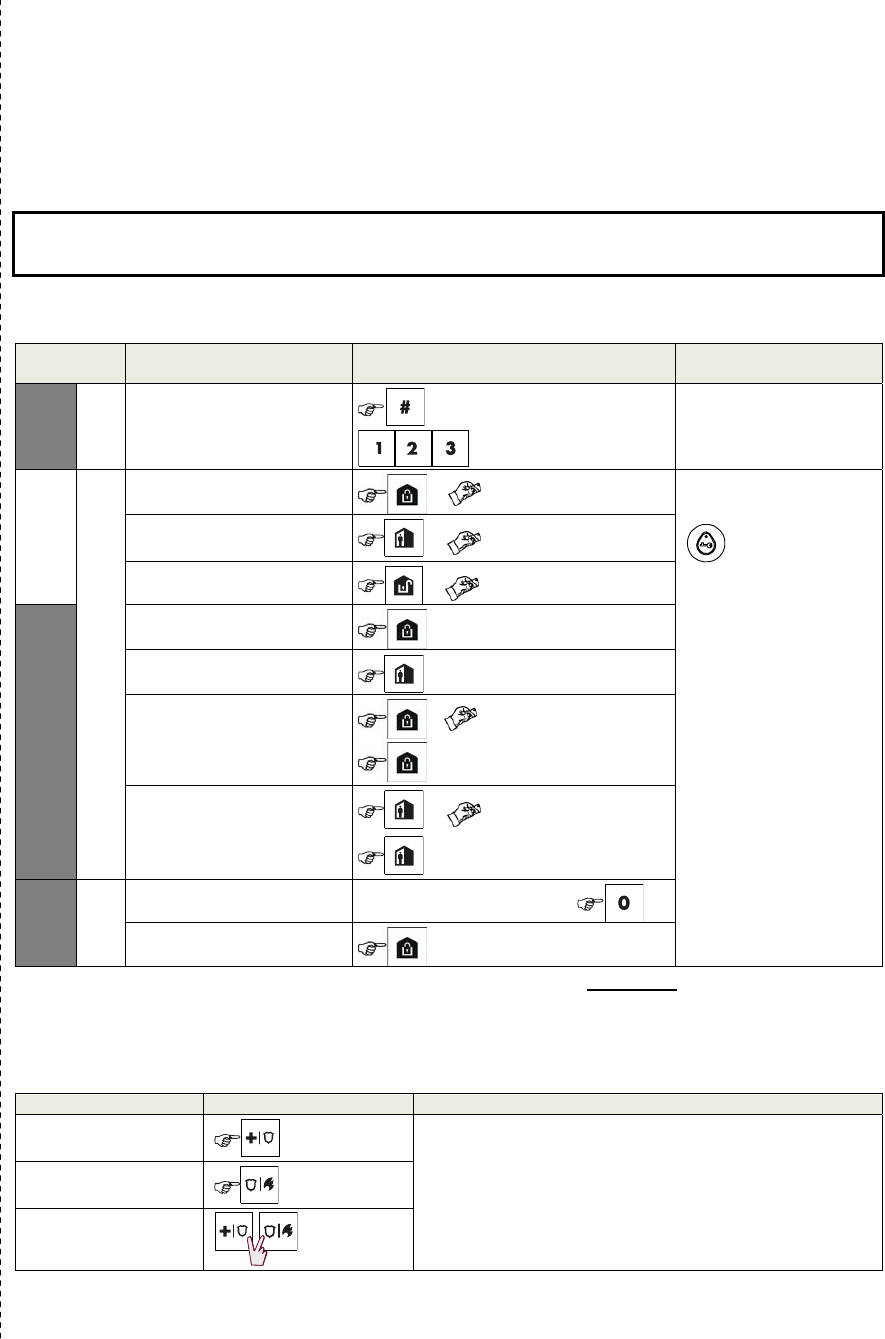
Arming and Disarming the System
Step Operation User Actions Key & Keypad
Response
Optional
1 Press the Partition Selection
button and then select a
PARTITION
(if Partition is enabled)
followed by any combination of The selected key blinks.
2
Arm AWAY + [ ] or enter code The selected key and the
"Present Prox Tag" LED
() begin to blink and
prompt you to present
your Tag or enter your
user code.
The keypad's LED blinks
red once to indicate
transmission of the
arming command to the
control panel.
The LED and the buzzer
then indicate the control
panel's response – refer
to the KP-250 PG2
User’s Guide, Chapter 4
“System Status and
Indications”.
Arm HOME
+ [] or enter code
Disarm (OFF)
+ [ ] or enter code
Optional
Quick arm AWAY
(If Quick Arm is enabled)
Quick arm HOME
(If Quick Arm is enabled)
Forced arming AWAY
(system not ready) + [ ] or enter code
to silence the “protest” buzzer
Forced arming HOME
(system not ready) + [] or enter code
to silence the “protest” buzzer
Optional
3 INSTANT
(After arming HOME/AWAY)
LATCHKEY
Note: The factory default master user code is 1111. The code is not required if quick arming has been permitted by the
installer. Change the factory default code to a secret code without delay (refer to the KP-250 PG2 User’s Guide,
Chapter 6, section B.4).
Initiating Alarms
Alarms Actions Notes
Emergency alarm
( 2 sec.)
When pressing the Fire or Emergency icons, the KP-250
PG2 starts beeping. After pressing the button for approx. 2
seconds, the KP-250 PG2 sends the command.
Fire alarm
( 2 sec.)
Panic alarm
( 2 sec.)

Preparing to Arm
Before arming, make sure that READY is displayed.
HH:MM READY
This indicates that all zones are secured and you may arm the system as desired.
If at least one zone is open (disturbed) the display will read:
HH:MM NOT READY
This indicates that the system is not ready for arming and in most cases that one or more
zones are not secured. However, it can also mean that an unresolved condition exists
such as certain trouble conditions, jamming etc., depending on system configuration.
To review the open zones click . The details and location of the first open zone detector (usually an open
door or window sensor) will be displayed. To fix the open zone, locate the sensor and secure it (close the door
or window) – see "device locator" below. Each click of will display another open zone or trouble indication.
It is highly recommended to fix the open zone(s), thus restoring the system to the state of “ready to arm”. If you
do not know how to do this, consult your installer.
Note: To quit at any stage and to revert to the "READY" display, click .
Device Locator: The PowerMaster system has a powerful device locator that helps you to identify open or
troubled devices indicated on the LCD display. While the LCD displays an open or faulty device, the LED on the
respective deice flashes indicating "it's me". The "it's me" indication will appear on the device within max. 16
seconds and will last for as long as the LCD displays the device.
Zone Bypass Scheme
Bypassing permits arming only part of the system and at the same time allowing free movement of people within
certain zones when the system is armed. It is also used to temporarily remove from service faulty zones that
require repair work or to deactivate a sensor if, for example, you are decorating a room.
You can set the Zone Bypass Scheme i.e. to scroll through the list of registered (enrolled) sensors to your
PowerMaster system and to Bypass (deactivate) faulty or disturbed sensors (either READY or NOT-READY) or
to Clear (reactivate) BYPASSED zones (sensors).
Once you have set a Bypass Scheme you can use the following 3 options:
To quickly review the bypassed zones – refer to Chapter 6, section A.2 of the KP-250 PG2 User’s Guide.
To quickly clear a bypassed zone i.e. to reactivate the bypassed zone – refer to Chapter 6, section A.1 of
the KP-250 PG2 User’s Guide.
To repeat (recall) the last used zone bypassing scheme – refer to Chapter 6, section A.3 of the KP-250 PG2
User’s Guide.
Notes:
1. Zones will be bypassed throughout one disarm-arm period only. Disarming the system after arming will
suspend the entire bypassing scheme but you can recall and reuse it as described in Chapter 6, section A.3
of the KP-250 PG2 User’s Guide.
2. Fire zones cannot be bypassed.