Visonic PMEXPRESS FULLY SUPERVISED WIRELESS ALARM CONTROL SYSTEM User Manual 1
Visonic Ltd. FULLY SUPERVISED WIRELESS ALARM CONTROL SYSTEM Users Manual 1
UserManual.wiki
>
Visonic
>
PMEXPRESS User Manual
>
Users Manual 1
Contents
1.
Users Manual 1
2.
Users Manual 2
Users Manual 1
Navigation menu
Upload a User Manual
Namespaces
Wiki Guide
HTML
PDF
Info
Views
User Manual
Discussion / Help
Navigation
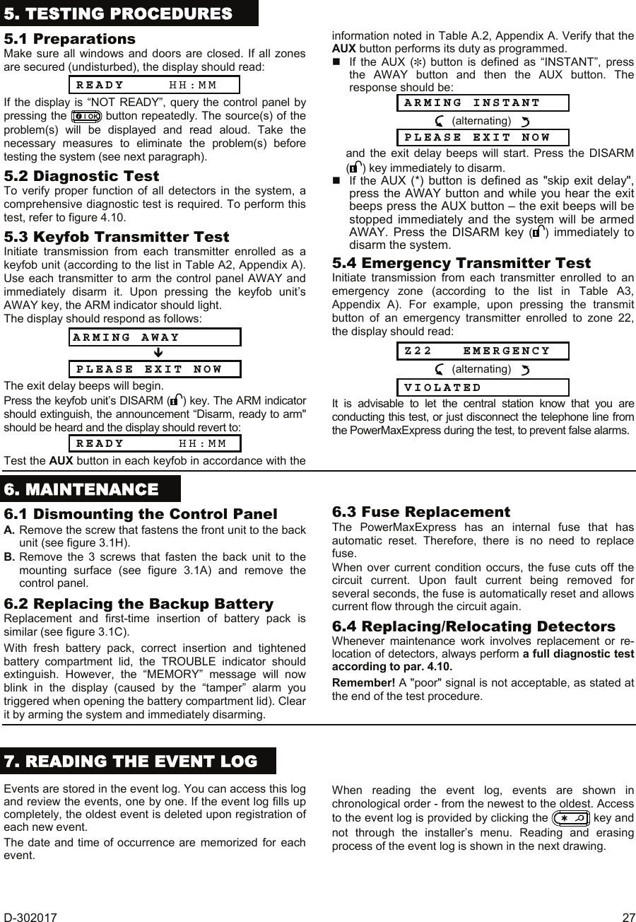
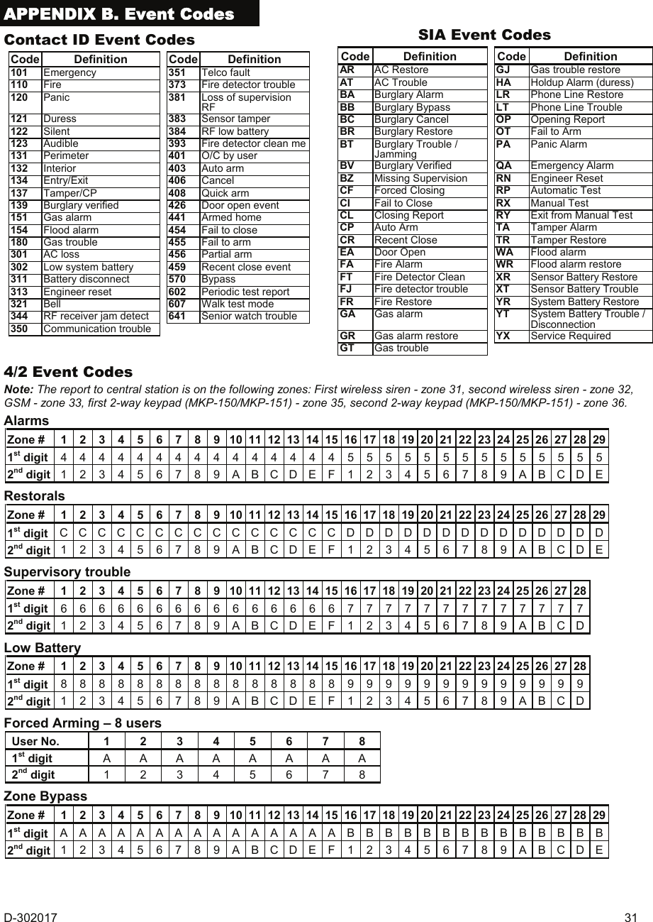
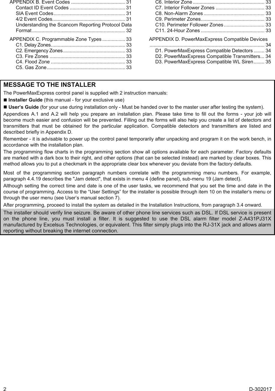
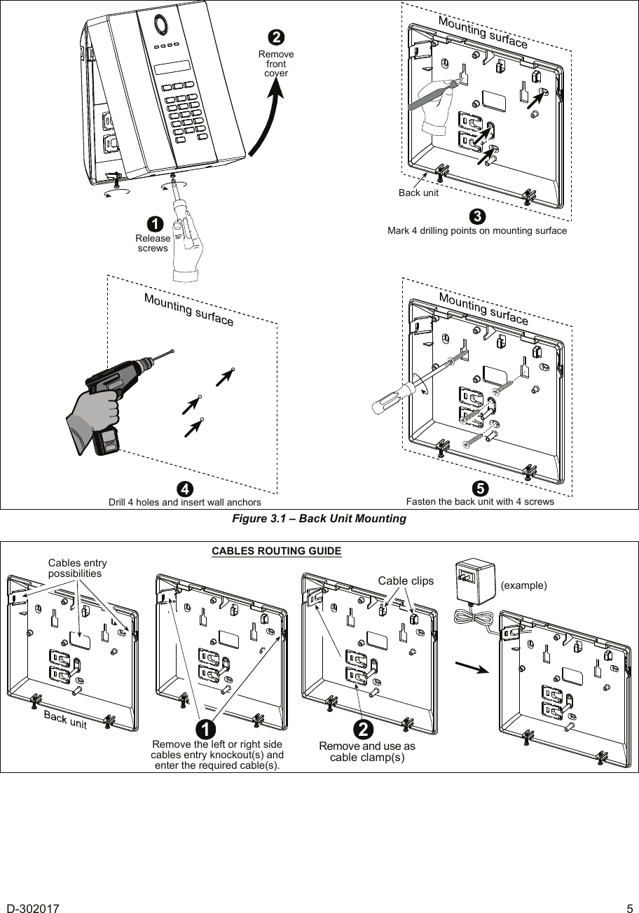
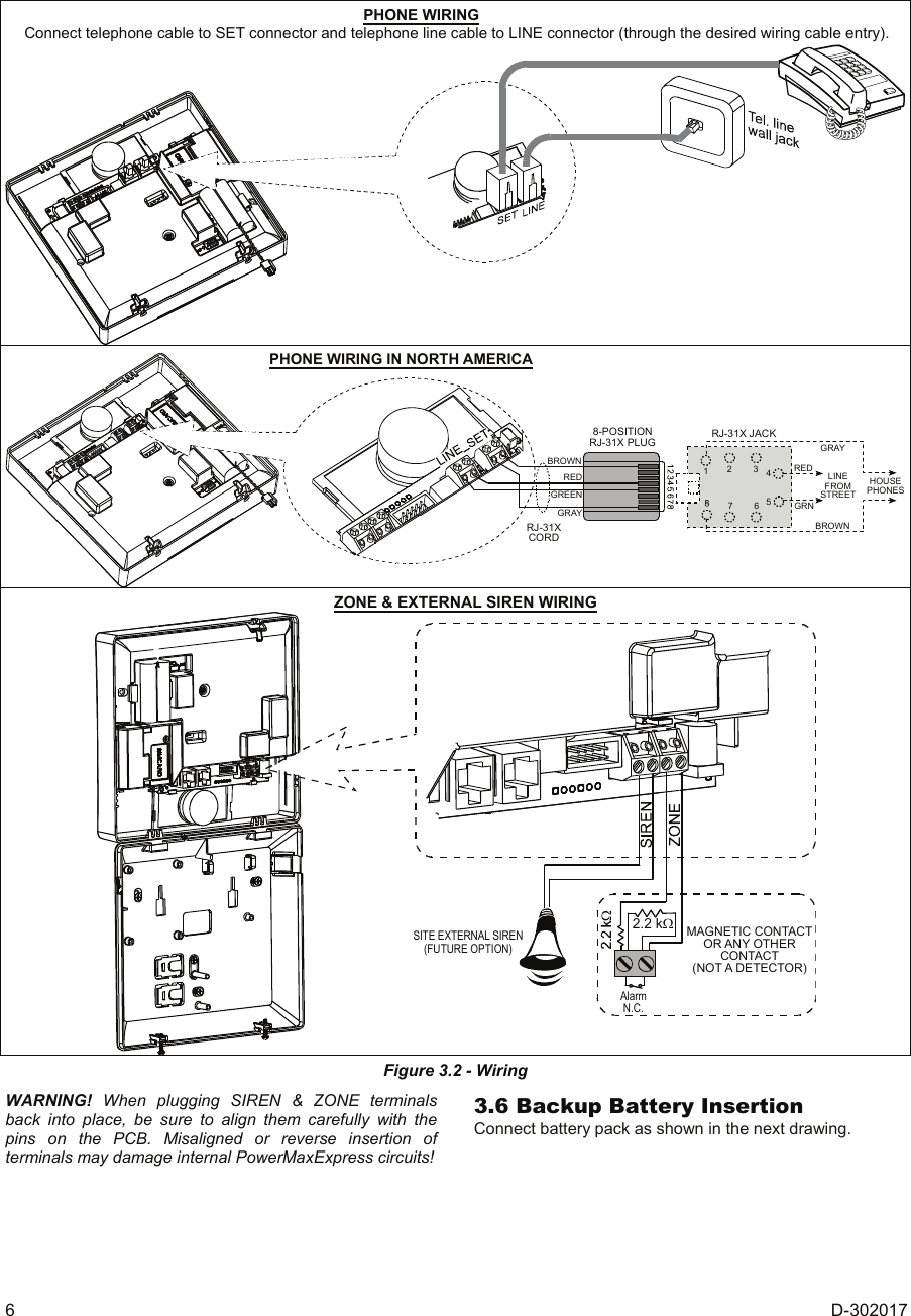
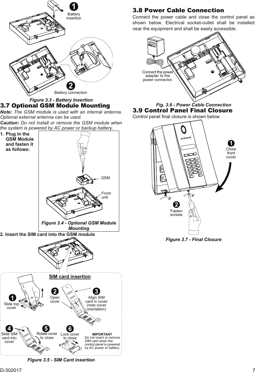
![D-302017 1 PowerMaxExpress Fully Supervised Wireless Alarm Control System Installer GuideTABLE OF CONTENTS 1. INTRODUCTION ....................................................... 3 2. SPECIFICATIONS..................................................... 3 2.1 General Data....................................................... 3 2.2 RF Section .......................................................... 3 2.3 Electrical Data ..................................................... 3 2.4 Communication ................................................... 4 2.5 Physical Properties ............................................. 4 3. INSTALLATION ......................................................... 4 3.1 Unpacking the Equipment................................... 4 3.2 Supplying Power to the Unit................................ 4 3.3 System Planning & Programming....................... 4 3.4 Mounting ............................................................. 4 3.5 Wiring.................................................................. 4 3.6 Backup Battery Insertion..................................... 6 3.7 Optional GSM Module Mounting ........................... 7 3.8 Power Cable Connection .................................... 7 3.9 Control Panel Final Closure................................ 7 4. PROGRAMMING....................................................... 8 4.1 INTRODUCTION ................................................ 8 4.1.1 General Guidance............................................ 8 4.1.2 Entering an Invalid Installer Code ....................... 8 4.1.3 Installer’s Menu................................................ 8 4.1.4 Setting a New Installer Code ........................... 8 4.1.5 Setting a New Installer Code in PowerMaxExpress that has 2 Installer Codes........... 8 4.2 ENROLLING WIRELESS DEVICES AND KEYFOB TRANSMITTERS........................................................... 9 4.2.1 General Guidance............................................ 9 4.2.2 Enrolling Type .................................................. 9 4.2.3 Enroll/Delete Sensors ...................................... 9 4.2.4 Enroll/Delete Keyfob Transmitters ......................... 9 4.2.5 Enroll/Delete Wireless Commander........................ 9 4.2.6 Enroll/Delete 2-Way Keypad ............................ 9 4.2.7 Enroll/Delete Wireless Siren............................. 9 4.3 DEFINING ZONE TYPES, NAMES, CHIME ZONES & PARTITION .............................................................. 11 4.4 DEFINING CONTROL PANEL PARAMETERS.... 12 4.4.1 Preliminary Guidance..................................... 12 4.4.2 Entry Delays 1&2 ............................................. 12 4.4.3 Exit Delay ....................................................... 12 4.4.4 Bell Time ........................................................ 12 4.4.5 Abort Time...................................................... 12 4.4.6 Alarm Cancel.................................................. 12 4.4.7 Quick Arm ...................................................... 12 4.4.8 Bypass............................................................ 12 4.4.9 Exit Mode ....................................................... 13 4.4.10 Piezo Beeps................................................. 13 4.4.11 Trouble Beeps.............................................. 13 4.4.12 Panic Alarm.................................................. 13 4.4.13 Swinger Stop................................................ 13 4.4.14 Cross Zoning................................................ 13 4.4.15 Supervision .................................................. 13 4.4.16 NOT READY ................................................ 13 4.4.17 AUX Button A ............................................... 13 4.4.18 AUX Button B 2-W-KF.................................... 13 4.4.19 Jam Detect................................................... 13 4.4.20 Latchkey....................................................... 14 4.4.21 “Not Active” .................................................. 14 4.4.23 Duress.......................................................... 14 4.4.24 Piezo Siren................................................... 14 4.4.25 Reset Option................................................ 14 4.4.26 Tamper Option............................................. 14 4.4.27 Siren On Line............................................... 14 4.4.28 Memory Prompt ........................................... 14 4.4.29 Disarm Option.............................................. 14 4.4.30 Bell/Rep. Option........................................... 14 4.4.31 Low-Bat Ack................................................. 14 4.4.32 Screen Saver ............................................... 14 4.4.33 Confirm Alarm.............................................. 14 4.4.34 AC FAIL REP............................................... 14 4.4.36 User Permission .......................................... 15 4.4.39 Key Zones Options (Optional) ..................... 15 4.5 DEFINING COMMUNICATION PARAMETERS... 17 Preliminary Guidance.............................................. 17 4.5.1 PSTN / GSM (Fig. 4.5 Detail A)....................... 17 4.5.2 GPRS / BB [Fig. 4.5 Detail B] ........................ 17 4.5.3 C.S. Reporting (Fig. 4.5 Detail C).................. 18 4.5.4 Private Report (Fig. 4.5 Detail D).................... 19 4.6 GSM Auto Detection.............................................. 23 4.7 BBA Auto Detection............................................... 23 4.9 DEFINE CUSTOM................................................. 24 4.10 DIAGNOSTIC TEST............................................ 24 4.11 USER FUNCTIONS ............................................ 25 4.12 RETRIEVING FACTORY DEFAULTS ................ 25 4.13 SERIAL NUMBER ............................................... 25 4.14 CALLING UPLOAD/DOWNLOAD SERVER....... 25 4.15 ENABLING/DISABLING PARTITIONS ............... 26 4.16 WALK-TEST ........................................................ 26 5. TESTING PROCEDURES ...................................... 27 5.1 Preparations...................................................... 27 5.2 Diagnostic Test ................................................. 27 5.3 Keyfob Transmitter Test ................................... 27 5.4 Emergency Transmitter Test ............................ 27 6. MAINTENANCE ...................................................... 27 6.1 Dismounting the Control Panel......................... 27 6.2 Replacing the Backup Battery .......................... 27 6.3 Fuse Replacement............................................ 27 6.4 Replacing/Relocating Detectors ....................... 27 7. READING THE EVENT LOG .................................. 27 APPENDIX A. Detector Deployment & Transmitter Assignments ................................................................ 29 A1. Detector Deployment Plan.................................. 29 A2. Keyfob Transmitter List....................................... 29 A3. Emergency Transmitter List................................ 30 A4. Non-Alarm Transmitter List................................. 30](https://usermanual.wiki/Visonic/PMEXPRESS.Users-Manual-1/User-Guide-1120410-Page-1.png)
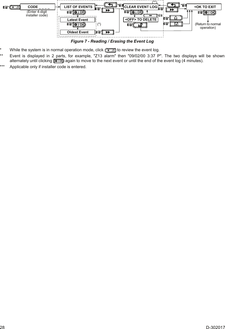
(See figure 4.10)(See fig. 4.1b & 4.1c)(See par. 4.12)(Control Panelserial numberdisplay)<OK> TO EXIT(See section 4.14)(*)15. PARTITIONING (See figure 4.15)(**) (*) Applicable only when "USER PERMIT" function is enabled (see par. 4.4.36 - USER PERMIT) (**) Optional feature. Figure 4.1a - Installer’s Menu (See fig. 4.1a)1. NEW INSTL CODENEW INST. CODEINST. CODE xxxx[code] Figure 4.1b - Setting a New Installer Code (see note)](https://usermanual.wiki/Visonic/PMEXPRESS.Users-Manual-1/User-Guide-1120410-Page-8.png)
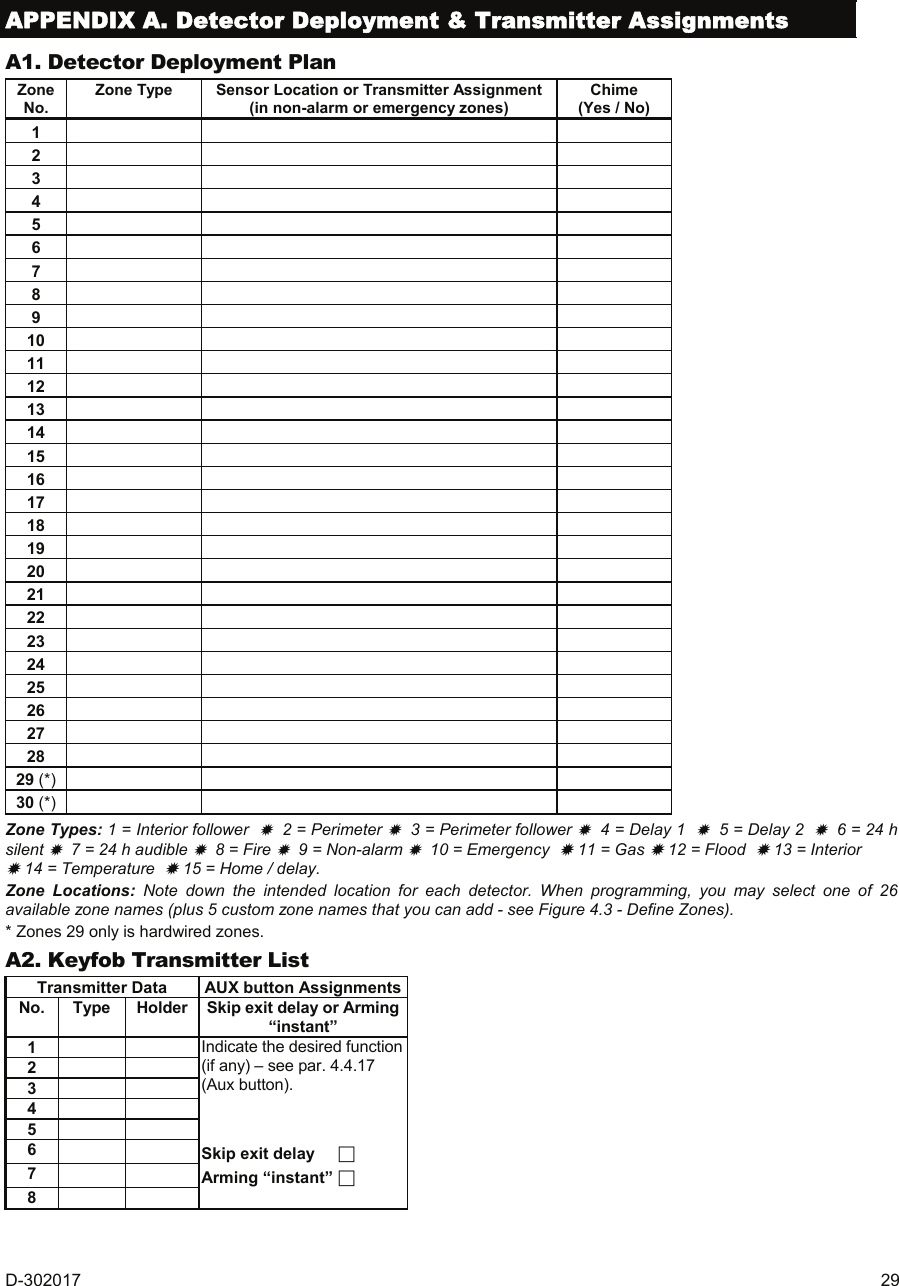
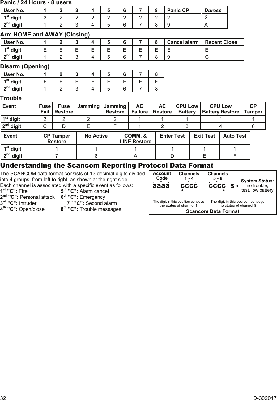
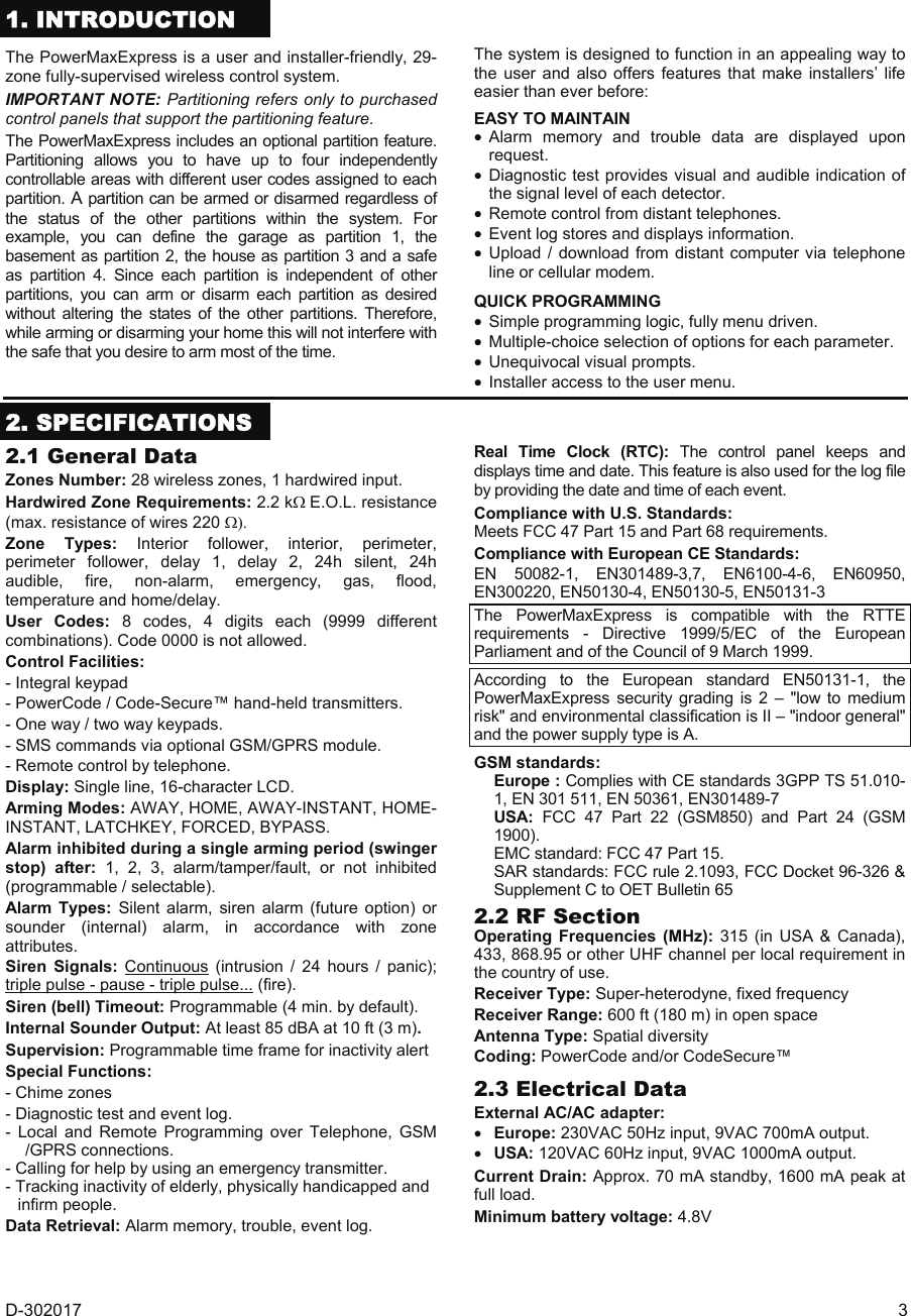
![D-302017 9 By using INSTALLER CODEINST. CODE xxxxNEW INST. CODE[code]1. NEW INSTL CODE(see fig. 4.1a) (see fig. 4.1a)[code]1. NEW INSTL CODENEW MASTER CODEMASTER CODE xxxx[code]INST. CODE xxxxNEW INST. CODEBy usingMASTER INSTALLER CODEFigure 4.1c - Setting a New Installer Code in System with Inst. & Master Inst. Codes (see note) Note: Installer Code should never be programmed as “0000”. Doing so will lock the user out of the installer menu! 4.2 ENROLLING WIRELESS DEVICES AND KEYFOB TRANSMITTERS 4.2.1 General Guidance The ENROLLING mode has the following sub-modes: • ENROLLING TYPE (wireless devices) • ENROLL SENSORS. • ENROLL KEYFOB (multi-button CodeSecure transmitters) • ENROLL WL 1WAY KP (wireless commander MCM-140+) • ENROLL WL 2WAY KP (wireless 2-way keypad MKP-150/ MKP-151) • ENROLL WL SIREN (wireless siren) Before beginning, gather all the devices that you intend to enroll and make sure they all have batteries installed. Your control panel must recognize the unique identification code (ID) of each such device in order to supervise them, receive their signals and respond accordingly. Attention! CodeSecure transmitters are mainly used for arming/disarming and can not be enrolled to zones. In order to enroll to zones, use only non-CodeSecure wireless devices. 4.2.2 Enrolling Type Here you determine whether to enroll a wireless device by normal transmission or by device Tamper function (opening its cover). Options: normal, or by tamper. 4.2.3 Enroll/Delete Sensors Wired detector can be enrolled in zone 29 and wireless detectors can be enrolled in zones 01-28. STOP • Before enrolling, the lens at the front of PIR and dual-technology sensors should be masked to prevent inadvertent transmission. • Make sure that magnetic contact transmitter is together with its magnet, to prevent it from sending alarm transmission. To enroll / delete wired / wireless sensors, refer to Fig. 4.2. 4.2.4 Enroll/Delete Keyfob Transmitters Keyfob transmitters are multi-button wireless CodeSecure™ transmitters. Eight system users use them for better, quicker and safer control over various system functions. To enroll / delete 1-way or 2-way keyfob transmitters, refer to figure 4.2. 4.2.5 Enroll/Delete Wireless Commander The Wireless Commander (MCM-140+) is a remote control unit that enables the user to remotely control the system. To enroll / delete up to 8 wireless commanders, refer to figure 4.2 (Enroll WL 1-way KP). 4.2.6 Enroll/Delete 2-Way Keypad The 2-way keypad, type MKP-150/MKP-151, enables the user to remotely control the system and also to receive data from the system (alarm and trouble data). To enroll up to two 2-way keypads, refer to figure 4.2. 4.2.7 Enroll/Delete Wireless Siren The wireless siren is a remote siren that is activated upon predefined events by the PowerMaxExpress system. To enroll / delete up to 2 wireless sirens, refer to figure 4.2.](https://usermanual.wiki/Visonic/PMEXPRESS.Users-Manual-1/User-Guide-1120410-Page-9.png)
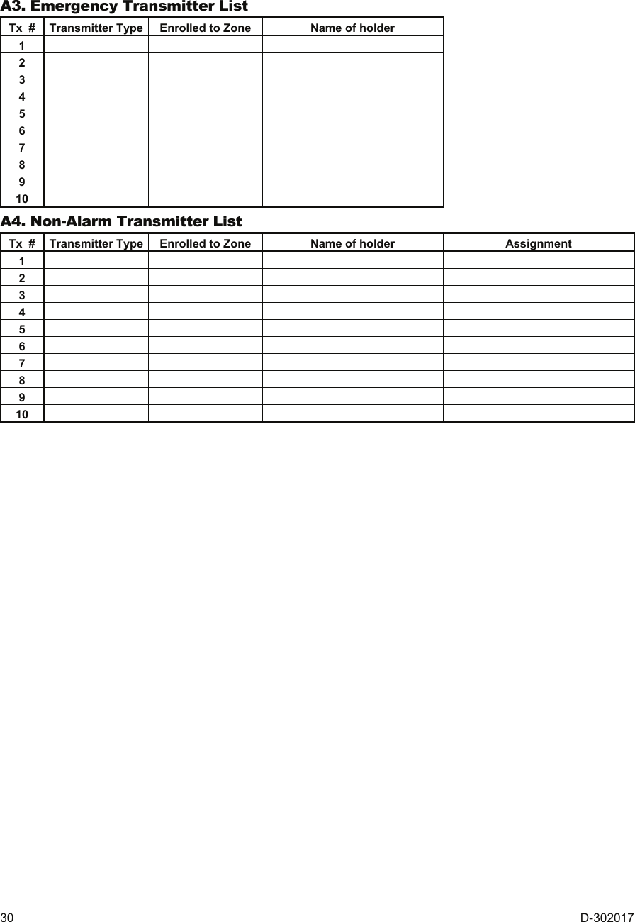
Deleting a Keyfob(*)(**)(pressanykey)Keyfob No: 5TRANSMIT NOWKEYFOB No: 05 for nextenrolling actionEnrolling a Keyfob(**)ZONE No: 05<OFF> TO DELETEZONE No: 05[WL Zone No.01-28] (e.g. 05)(**)Deleting wired/WL sensorZONE No: 05[Initiate transmission)ZONE No: 05TRANSMIT NOW(**)Enrolling a WL Sensor(***) for nextenrolling actionZONE No: 29ZONE No: 29Enrolling wired sensor for nextenrolling action[wired Zone No.29/30] (e.g. 29)<OK> TO ENROLLENROLL SENSORSZONE No: - -SET SENSITIV.higher sensitivitylower sensitivitySelect byor(****)[wired/WL Zone No.01-30] (e.g. 05)USER SETTINGSENTER CODE1. NEW INSTL CODE2. ENROLLING3. DEFINE ZONES[installer code]INSTALLER MODE<OK> TO EXITENROLLING TYPEnormal enrollby tamperPartitionPartition 1[select partition 1 - 4]ENROL WL 1WAY KP[WL 1-way keypadNo. 1 to 8] (e.g. 5)1way kp No :1way kp No : 5 1way kp No : 5(**)<OFF> TO DELETEkey untilred LEDlightsTRANSMIT NOWDeleting a wirelessCommander MCM-140+1way kp No: 5*pressENROL WL 2WAY KP[MKP-150/151No. 1 or 2] (e.g. 2)2way kp No:2way kp No : 2 2way kp No : 2(**)<OFF> TO DELETETRANSMIT NOWEnrolling a wirelesskeypad MKP-150/151 for nextenrolling actionENROL WL SIREN[WL siren No.1 or 2] (e.g. 2)SIREN No :siren No : 2 siren No : 2(**)Momentarily press thewireless siren self-testbutton until a squawk isheard (1 sec. approx.)TRANSMIT NOWEnrolling awireless sirensiren No: 2 for nextenrolling actionAWAY2way kp No: 2Deleting a wirelesskeypad MKP-150/151Press MKP-150/151back tamperswitch once(see MKP-150/151inst. instructions)2way kp No: 2<OFF> TO DELETEDeleting awireless sirensiren No: 2Open WLsiren coverand removeits battery1way kp No: 5Enrolling a wirelessCommander MCM-140+ for nextenrolling actionPartition 1[select partition 1 - 4]Partition(*****)Note: Applies onlywhen in Partition modeNote: Applies onlywhen in Partition mode(First display is READYor NOT READY)READY 00:00NORMAL MODE Figure 4.2 - Enrolling / Deleting Wireless Devices / Keyfobs / Wireless Commanders / Wireless Sirens * Keyfob enrolling can be performed by the installer or by the user (via USER SETTINGS menu). ** A black box in the display means that a device is enrolled (the system has learned its ID). No black box indicates that the device is not enrolled. *** Initiate either normal transmission or the device tamper function (see ENROLLING TYPE, Par. 4.2.2). **** Select "higher" sensitivity for far wireless device, "lower" for near devices. ***** MKP-150/151 is not compatible for use when partition is enabled.](https://usermanual.wiki/Visonic/PMEXPRESS.Users-Manual-1/User-Guide-1120410-Page-10.png)
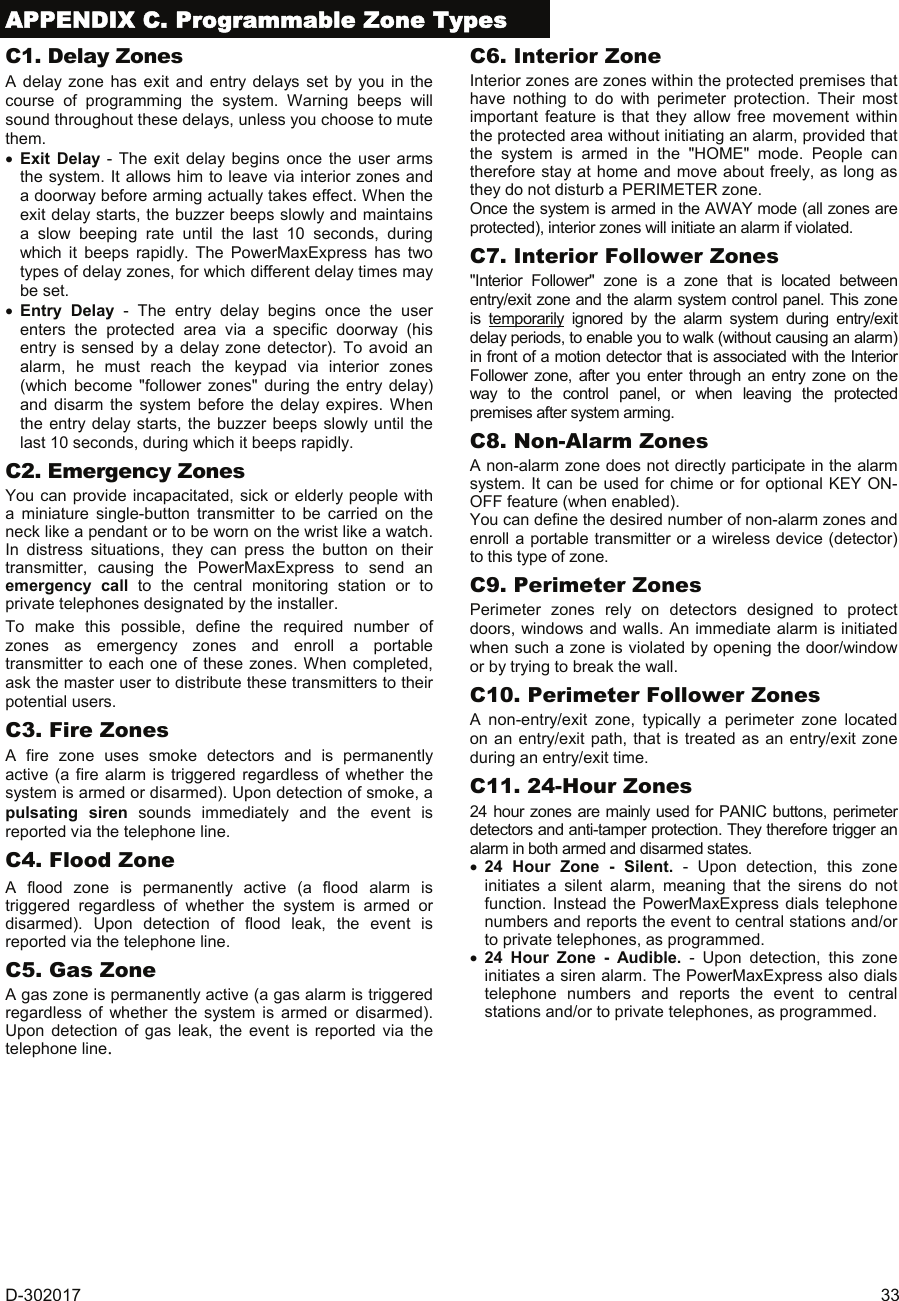
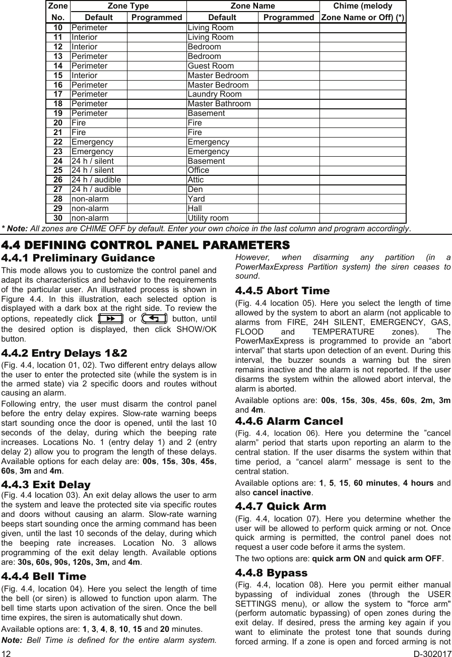
![D-302017 11 4.3 DEFINING ZONE TYPES, NAMES, CHIME ZONES & PARTITION This mode allows you to assign one of 15 zone types to each of the system's 29 (wireless & wired) zones. In addition, it also allows you to assign a name to each zone and determine whether the zone will operate as a chime zone (only while the system is in the disarmed or Home arming state). When a chime zone is triggered, chime melody or zone name is heard (there are 2 selectable chime modes - Melody chime or Chime Off). A list of factory defaults is printed in table 1. You may fill out the blank columns even before you start and proceed to program according to your own list. Remember! A delay zone is also a perimeter zone by definition. Zone types are fully explained in Appendix C. Selectable Zone NamesDining roomDownstairsEmergencyFireFront doorGarageGarage doorGuest roomHallKitchenLaundry roomLiving roomMaster bathMaster bdrmOfficeUpstairsUtility roomYardCustom 1Custom 2Custom 3Custom 4Custom 5AtticBack doorBasementBathroomBedroomChild roomClosetDen31 zone names can be selected, 26 fixed names and 5custom names (defined by the installer - see chap. 4.9):ZONE No: - -Zxx: TYPE -[Zone No.] (e.g. 05)1. Inter-follow2. PerimeterZxx: NAME - -AtticBack doorBasementBathroomBedroomChild roomCloset(*)(*)4. Delay 15. Delay 26. 24h silent7. 24h audible8. Fire9. Non-alarm10. Emergency3. Perim-follow(see list above)11. Gas12. Flood13. Interior3. DEFINE ZONES[installer code]USER SETTINGSENTER CODE2. ENROLLINGINSTALLER MODE<OK> TO EXIT14. Temperature15. Home/DelayRefer to Figure 4.1ato gain access toUSER SETTINGSmenuZxx: CHIMEMelody-chimeChime off(*)Zxx: PARTITIONPartition 1(*)Partition 2Partition 3Partition 4(see note)Zxx: KEY ON/OFFz-key enablez-key disable(*)(**)OPTIONAL Figure 4.3 - DEFINE ZONES Flow Chart * The currently saved option is displayed with a dark box at the right side. To review the options, repeatedly click or button, until the desired option is displayed, then click OKI (a dark box will be displayed at the right side). ** Clicking the OKI button in this location brings you to the same zone number that you are dealing with. Press or to select the next zone. Table 1 - DEFAULT AND PROGRAMMED ZONE DEFINITIONS Zone Zone Type Zone Name Chime (melody No. Default Programmed Default Programmed Zone Name or Off) (*) 1 Delay 1 Front Door 2 Delay 1 Garage 3 Delay 2 Garage Door 4 Perimeter Back Door 5 Perimeter Child Room 6 Interior Office 7 Interior Dining Room 8 Perimeter Dining Room 9 Perimeter Kitchen](https://usermanual.wiki/Visonic/PMEXPRESS.Users-Manual-1/User-Guide-1120410-Page-11.png)
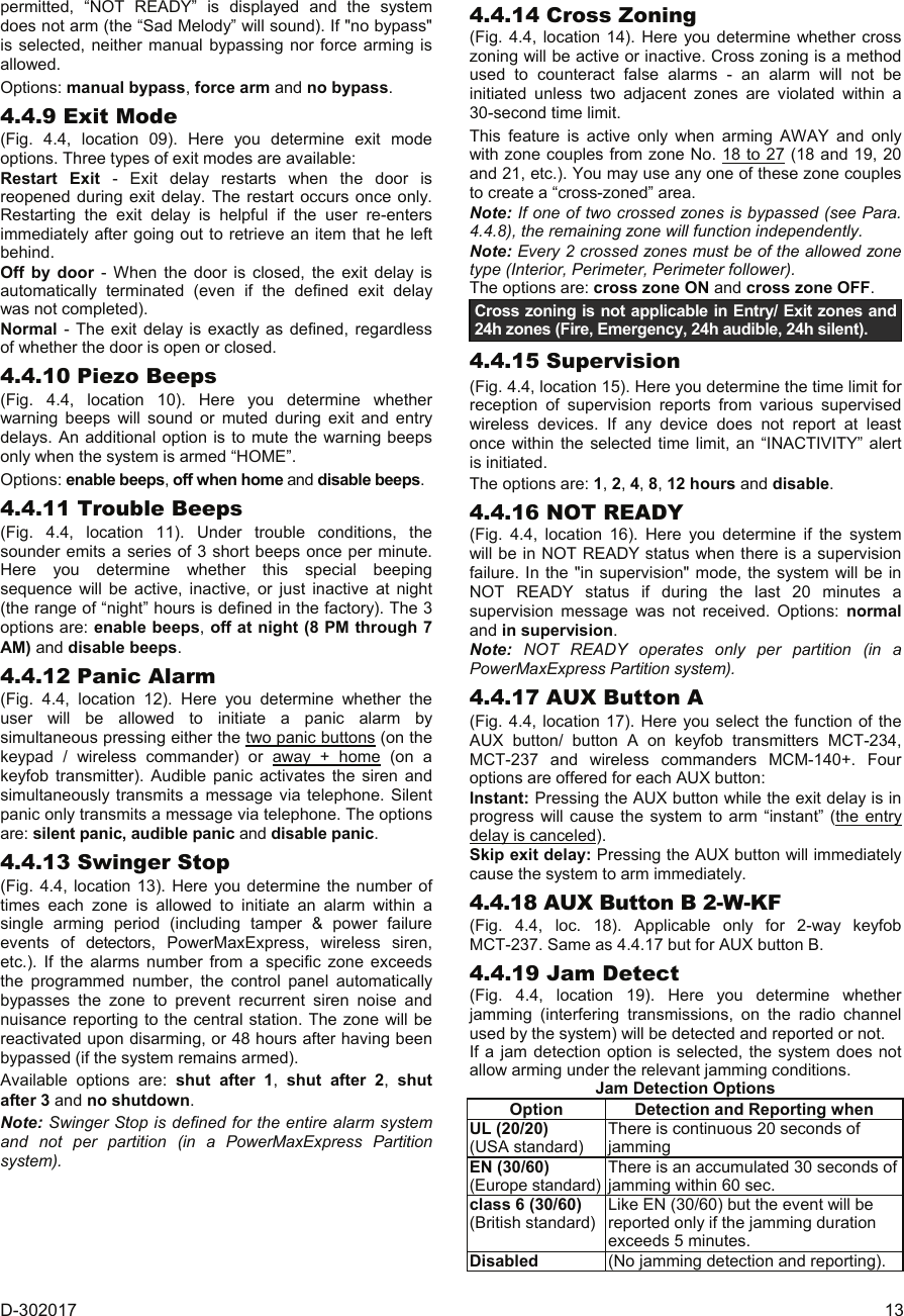
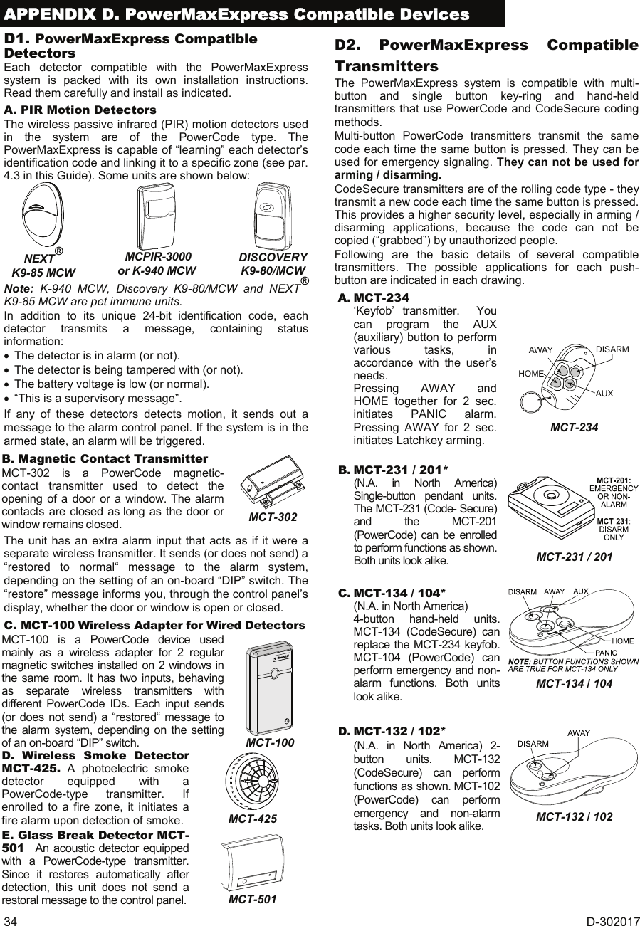
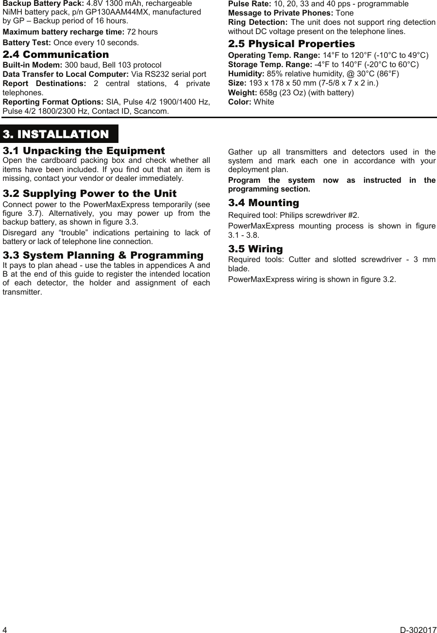
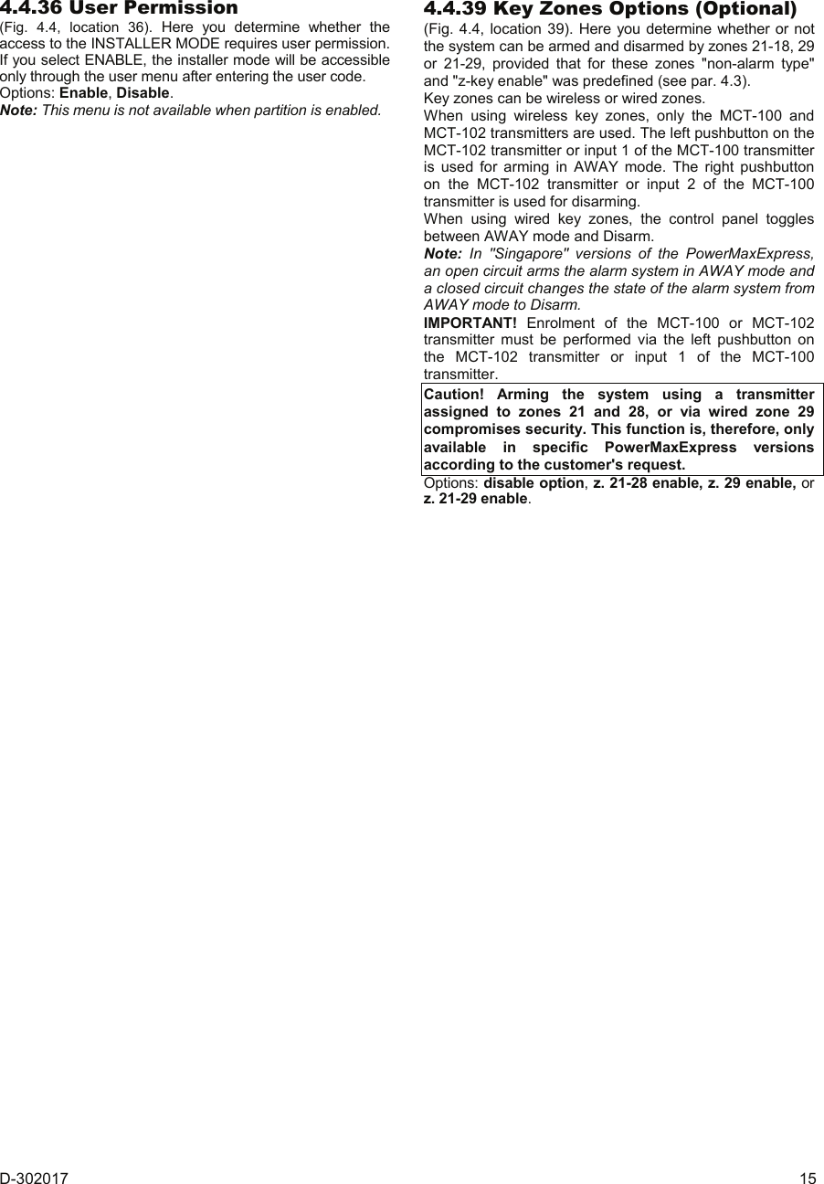
![14 D-302017 4.4.20 Latchkey (Fig. 4.4, location 20). Here you determine whether the system can be armed in the latchkey mode. If the system is armed this way, a “latchkey” message will be sent to specific telephones upon disarming by a “latchkey user” (users 5-8 or keyfob transmitters 5-8). This mode is useful when parents at work want to be informed of a child’s return from school. You can record a name for latchkey users. The options are: Latchkey ON and Latchkey OFF. 4.4.21 “Not Active” (Fig. 4.4, location 21). Here you determine the time limit for reception of signals from sensors used to monitor the activity of sick, elderly or disabled people. If no sensor detects and reports movement at least once within the defined time limit, a “not-active” alert is initiated. Options: 3, 6, 12, 24, 48, 72 hours and no act disable. Note: The Not Active timer is defined for the entire alarm system for the above hour options and not per partition (in a PowerMaxExpress Partition system). Subsequently, a dedicated timer is assigned to each partition. 4.4.23 Duress (Fig. 4.4, loc. 23). A duress alarm (ambush) message can be sent to the central station if the user is forced to disarm the system under violence or menace. To initiate a duress message, the user must disarm the system with the duress code (2580 by default). Here you can change the code digits or enter "0000" to disable the duress feature. The system does not allow the user to program the duress code saved in this memory location as an existing user code. 4.4.24 Piezo Siren (Fig. 4.4, location 24). Here you determine whether the internal siren will sound or remain silent upon alarm (according to the user preference). Options: piezo siren on, piezo siren off. 4.4.25 Reset Option (Fig. 4.4, location 25). (Not applicable in the USA) Here you determine whether the system can be rearmed (after an event) by the user or only by the installer. Options: user reset or engineer reset. If Engineer Reset is selected, the system can be rearmed only by the installer; by entering and exiting the installer menu, by entering and exiting the event log (see section 7), or by remote telephone. To perform Engineer Reset via the telephone, establish communication with the PowerMaxExpress (see user guide, par. 6.3A, steps 1-5) and continue as follows: a. [*], [installer code], [#] b. Wait for 2 beeps c. [*], [1], [#] d. [*], [99], [#] Note: This menu is not available when partition is enabled. 4.4.26 Tamper Option (Fig. 4.4, location 26). Here you determine whether zone tamper will be reported or ignored. Available options are: zone tamper ON and zone tamper OFF. 4.4.27 Siren On Line (Fig. 4.4, location 27). Here you determine whether the siren will be activated or not when the telephone line fails during system armed state. Available options are: enable on fail, disable on fail. 4.4.28 Memory Prompt (Fig. 4.4, location 28). Here you determine whether the user will receive indication that an alarm has been activated. Available options are: enable and disable. 4.4.29 Disarm Option (Fig. 4.4, location 29). Here you determine when it is possible to disarm the system: A. Any time. B. In AWAY mode, during entry delay, by using the PowerMaxExpress keypad or wireless sensor (keyfob). C. In AWAY mode, during entry delay, by using a wireless device (keyfob) only (this is set as a default in UK to comply with DD243). D. During entry delay, or by using the PowerMaxExpress keypad in AWAY mode. Options: any time, on entry all, on entry wireless, or entry + away kp. 4.4.30 Bell/Rep. Option (Fig. 4.4, location 30). Here you determine whether an alarm will be initiated (siren / report) when there is a supervision / jamming failure during AWAY arming state. Available options are: EN standard and other. When "EN standard" is selected, if there is supervision / jamming failure during AWAY arming, the siren is activated and the events are reported as tamper events. When "Other" is selected, there is no such activity during AWAY arming. 4.4.31 Low-Bat Ack (Fig. 4.4, location 31). Here you determine whether the user will hear or will not hear low battery sound when he tries to disarm the system with a keyfob whose battery voltage is low. Available options are: keyfob L-B on (the user has to acknowledge the keyfob low battery message) or keyfob L-B off (the user does not have to acknowledge the keyfob low battery message). 4.4.32 Screen Saver (Fig. 4.4, location 32). Here you can determine that if no key is pressed during more than 30 seconds, the display will be “PowerMax” (to prevent possible intruder of knowing the system status). You can determine that normal display will return after pressing the button followed by entering user code (Refresh by Code) or after pressing any key (Refresh by Key). If Refresh by Key is selected, the first pressing of any key (except Fire and Emergency) will cause normal display return and the second press will perform the key function. Regarding the Fire and Emergency keys, the first key press will cause normal display return and also will perform the Fire/Emergency function. Options: scrn saver OFF, refresh by code, refresh by key. 4.4.33 Confirm Alarm (Fig. 4.4, location 33). Here you determine that if 2 successive alarms will occur during a specific period, the second alarm will be considered as a confirmed alarm (for confirmed alarm reporting, (see par. 4.5.3). Options: disable 30 min., 45 min., 60 min., or 90 min. 4.4.34 AC FAIL REP (Fig. 4.4, location 34). Here you determine the time interval between AC power failure occurrence and the failure reporting. Options: 5 minutes, 30 minutes, 60 minutes or 180 minutes.](https://usermanual.wiki/Visonic/PMEXPRESS.Users-Manual-1/User-Guide-1120410-Page-14.png)
![16 D-302017 USER SETTINGSENTER CODE1. NEW INSTL CODE2. ENROLLING3. DEFINE ZONES5. DEFINE COMM[installer code]INSTALLER MODE05: ABORT TIME09: EXIT MODE13: SWINGER STOP17: AUX BUTTON Ainstant01: ENTRY DELAY 1 02: ENTRY DELAY 2 03: EXIT DELAY 04: BELL TIME06: ALARM CANCEL 07: QUICK ARMquick arm ONquick arm OFF08: BYPASSmanual bypassno bypassforce arm10: PIEZO BEEPS 11: TROUBLE BEEPS 12: PANIC ALARMcross zone ONcross zone OFF14: CROSS ZONING 15: SUPERVISIONsuperv time 1 hsuperv time 2 hsuperv time 4 hsuperv time 8 h16: NOT READYnormalin supervision4. DEFINE PANELentry dly2 00 sentry dly2 15 sentry dly2 30 sentry dly2 45 sentry dly2 60 sentry dly2 3 mentry dly2 4 mexit delay 30 sexit delay 60 sexit delay 90 sexit delay 120 sexit delay 3 mexit delay 4 mbell time 1 mbell time 4 mbell time 8 mbell time 10 mbell time 15 mbell time 20 mcancel time 1 mcancel time 5 mcancel time 15 mcancel time 60 mcancel time 4 hcancel inactiveenable beepsoff when homedisable beepsenable beepsoff at nightdisable beeps silent panicaudible panicdisable panicshut after 1shut after 2shut after 3no shutdownsuperv time 12 hdisableentry dly1 00 sentry dly1 15 sentry dly1 30 sentry dly1 45 sentry dly1 60 sentry dly1 3 mentry dly1 4 mabort time 00 sabort time 15 sabort time 30 sabort time 45 sabort time 60 sabort time 2 mabort time 3 mrestart exitoff by doornormalbell time 3 mabort time 4 mNote: Force arm is notapplicable to the UK.inUSAinUSAinUSA inUSA<OK> TO EXITskip exit delay19: JAM DETECTUL (20/20)EN (30/60)class 6 (30/60)disable21: NOT ACTIVEno act time 3 hno act time 6 hno act time 12 hno act time 24 hno act time 48 hno act time 72 hno act disable23: DURESSduress code 2580(Change the code orenter 0000 to disableduress function)Note: Duress code is notapplicable to the UK.24: PIEZO SIRENpiezo siren onpiezo siren off25: RESET OPTIONuser resetenginner resetNot applicablein the USA26: TAMPER OPTIONzone tamper onzone tamper off27: SIREN ON LINEenable on faildisable on fail28:MEMORY PROMPTenabledisable29: DISARM OPTIONany timeon entry wirelessentry + awake kpon entry allNot applicablein the USAinUK30: BELL/REP. OPTEN standardother31: LOW-BAT ACKkeyfob L-B onkeyfob L-B off32: SCREEN SAVERscrn saver OFFrefresh by coderefresh by key34: AC FAIL REP5 minutes30 minutes60 minutes180 minutes33: CONFIRM TIMEdisable30 minutes45 minutes60 minutes90 minutes20:LATCHKEYlatchkey onlatchkey off18: AUX B 2-W-KFinstantskip exit delayNote: Swinger Stop is definedfor entire alarm system.Refer to Figure 4.1ato gain access toUSER SETTINGSmenu36: USER PERMITenabledisableinUK39: KEY ZONES OPTz. 21-28 enabledisable optionz. 29 enablez. 21-29 enableNote: The currently savedoptions are displayed withdark box at the right side ofthe display. To review theoptions, repeatedly click or until thedesired option is displayed,then click OK (a dark boxwill be displayed at the rightside). Figure 4.4 - DEFINE PANEL Flow Chart](https://usermanual.wiki/Visonic/PMEXPRESS.Users-Manual-1/User-Guide-1120410-Page-16.png)
![D-302017 17 4.5 DEFINING COMMUNICATION PARAMETERS Preliminary Guidance This mode allows you to adapt the telephone communication parameters to the local requirements. Compatible central station receivers are: Osborne-Hoffman model 2000, Ademco Model 685, FBII Model CP220, Radionics Model D6500, Sur-Gard Model SG-MLR2-DG and Silent Knight Model 9500. IMPORTANT: In telephone / pager number locations and account number locations, you may be required to enter hexadecimal digits. In telephone number locations, these digits are used as codes to control the dialer: Hex.Digit Keying Sequence Code Significance A <#> ⇒ <0> Applicable only at the beginning of a number - the dialer waits 10 seconds or waits for dial tone, whichever comes first and then dials. D <#> ⇒ <3> Applicable only at the beginning of a number - the dialer waits 5 seconds for dial tone and goes on hook if none is received. E <#> ⇒ <4> Applicable only in the middle of the number - the dialer waits 5 seconds F <#> ⇒ <5> Not applicable in phone numbers Note: A "+" can be entered at the beginning of the line by pressing and then . To enter a series of digits, use the following keys: <Numeric keypad> - to enter the number - moves the cursor from left to right - moves the cursor from right to left - deletes everything after the cursor (to the right) 4.5.1 PSTN / GSM (Fig. 4.5 Detail A) Area Code [Fig 4.5.1(1)] Here you enter the system tel. area code (up to 4 digits). Line Prefix [Fig 4.5.1(2)] Here you enter the number that is used as a prefix to access an outside telephone line (if exists). Dial Method [Fig 4.5.1(3)] Here you determine the dialing method used by the automatic dialer built into the PowerMaxExpress control panel. The options are: Pulse and tone (dtmf). GSM Keep Alive [Fig 4.5.1(4)] Here you prevent the GSM service provider from disconnecting the GSM line if the user has not initiated any outgoing telephone calls during the last 28 days. The options are: disable and every 28 days. 4.5.2 GPRS / BB [Fig. 4.5 Detail B] The GSM/GPRS module is capable of communicating with the Central Station receiver by GPRS, GSM Voice and SMS channels. Each of the channels can be separately enabled or disabled in order to allow or prohibit the module from using it for the event reporting. If all channels are enabled, the GSM/GPRS module will always try GPRS first. If fails, it will try GSM Voice. If fails, it will try any other possible method (PSTN, Broadband) and only then it will try SMS. This is due to the fact that SMS is the most unreliable option of communication. Disabling any of the GSM Module channels will cause the module to use a different sequence than the one described above. GPRS Report [Fig 4.5.2(1)] Here you determine whether the alarm system will report events to the central station via the GPRS channel. The options are: disable and enable. GSM Report [Fig 4.5.2(2)] Here you determine whether the alarm system will report events to the central station via the GSM voice channel. The options are: disable and enable. SMS Report [Fig 4.5.2(3)] Here you determine whether the alarm system will report events to the central station via the SMS channel. The options are: disable and enable. GPRS APN [Fig 4.5.2(4)] Here you enter the name of the APN (Access Point) used for the internet settings for the GPRS (up to 40 digits). GPRS Username [Fig 4.5.2(5)] Here you enter the username of the APN used for GPRS communications (up to 30 digits). GPRS Password [Fig 4.5.2(6)] Here you enter the password of the APN used for GPRS communications (up to 16 digits). The following table provides a list of the keys used by the PowerMaxExpress editor for the GPRS APN, GPRS Username, GPRS Password menus and Custom Zone Name option. Key Functionality Moves the cursor from left to right. Long press for speed. Moves the cursor from right to left. Long press for speed. Scrolls upward the sequence of inserted digits. Long press for speed. Scrolls downward the sequence of inserted digits. Long press for speed. Places cursor to extreme right position of edit string and shows the last 16 digits of edit string. Reverts to previous or top menu without saving the edit string. Reverts to "<OK> TO EXIT" without saving the edit string. OKISaves and reverts to previous menu. Clears all digits to the right of cursor. Clears one digit by cursor. Selects between uppercase or lowercase digits. PIN Code [Fig 4.5.2(8)] Enter PIN code of the SIM card installed in the PowerMaxExpress unit (up to 16 digits). Force Home Network [Fig 4.5.2(9)] Here you determine whether to force the SIM card to use the home network only and not to select another network in case the home network cannot be found. The options are: disable and enable.](https://usermanual.wiki/Visonic/PMEXPRESS.Users-Manual-1/User-Guide-1120410-Page-17.png)
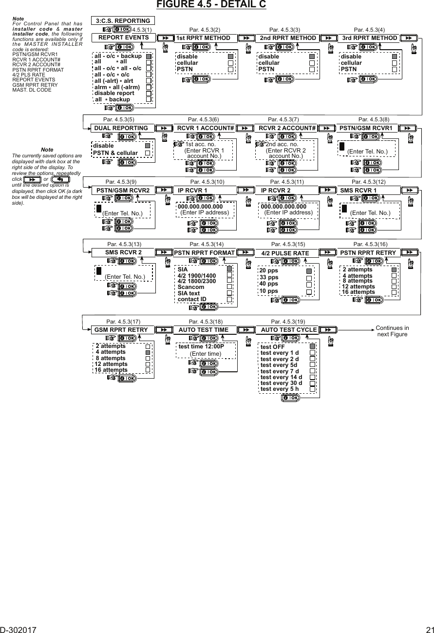
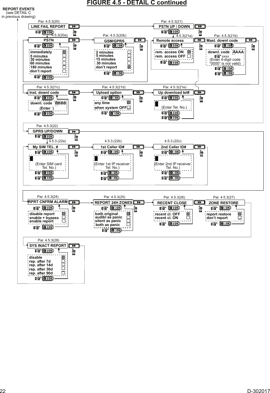
![18 D-302017 4.5.3 C.S. Reporting (Fig. 4.5 Detail C) Report Events [Fig 4.5.3(1)] – see note in Fig. 4.5 Detail C Here you determine which types of event will be reported to central stations. Due to lack of space in the display, abbreviations are used: alarm is “alrm”, alert is “alrt” and open/close is “o/c”. The asterisk (J) is a separator between events reported to central station 1 and events reported to central station 2. Messages are divided by type into four groups: No. Group Events Reported 1 Alarms Fire, Burglary, Panic, Tamper 2 Open/close Arming AWAY, Arming HOME, Disarming 3 Alerts No-activity, Emergency, Latchkey, Gas, Flood, Temperature 4 Maintenance Low-battery AC failure "Alarm" group has the highest priority and "Alert" group has the lowest priority. The selectable options are as follows: Plan name Sent to center 1 Sent to center 2 all -o/c J backup All but open/close All but open/close if center 1 doesn’t respond all J all All All all-o/c J all -o/c All but open/close All but open/close all –o/c J o/c All but open/close Open/close all (–alrt) J alrt All but alerts Alerts Alrm J all (–alrm) Alarms All but alarms Disable report Nothing Nothing all J backup All All if cent. 1 doesn’t respond Note: “All” means that all 4 groups are reported and also trouble messages - sensor / system low battery, sensor inactivity, power failure, jamming, communication failure etc. 1st Report Method [Fig 4.5.3(2)] Here you define the 1st priority of method used to report events. The options are: disable, cellular and PSTN. 2nd Report Method [Fig 4.5.3(3)] Here you define the 2nd priority of method used to report events. If the method defined to report events in the 1st priority fails, the control panel will attempt to report using the method defined in the 2nd priority (see notes in 1st Report Method). The options are: disable, cellular and PSTN. 3rd Report Method [Fig 4.5.3(4)] Here you define the 3rd priority of method used to report events. If the method defined to report events in the 2nd priority fails, the control panel will attempt to report using the method defined in the 3rd priority (see notes in 1st Report Method). The options are: disable, cellular and PSTN. Dual Reporting [Fig 4.5.3(5)] Here you determine whether to report events using PSTN and cellular at the same time instead of waiting for the 1st method to fail before trying the 2nd method. The options are: disable and PSTN & cellular. Receiver 1 Account No. [Fig 4.5.3(6)] - see note in Fig. 4.5 Detail C Here you enter the number that will identify your specific alarm control system to the 1st central station. The number consists of 6 hexadecimal digits. Receiver 2 Account No. [Fig 4.5.3(7)] - see note in Fig. 4.5 Detail C Here you enter the number that will identify your system to the 2nd central station. The account number consists of 6 hexadecimal digits. PSTN/GSM RCVR1 [Fig 4.5.3(8)] - see note in Fig. 4.5 Detail C Here you program telephone number of the 1st central station (including area code, 16 digit max) to which the system will report the event groups defined in Report Events. PSTN/GSM RCVR2 [Fig 4.5.3(9)] - see note in Fig. 4.5 Detail C Here you program telephone number of the 2nd central station (including area code, 16 digit max) to which the system will report the event groups defined in Report Events. IP RCVR 1 [Fig 4.5.3(10)] Here you enter the IP address of the IP receiver that is located in the 1st central station. IP RCVR 2 [Fig 4.5.3(11)] Here you enter the IP address of the IP receiver that is located in the 2nd central station. SMS RCVR 1 [Fig 4.5.3(12)] Here you enter the telephone number of the SMS receiver that is located in the 1st central station. SMS RCVR 2 [Fig 4.5.3(13)] Here you enter the telephone number of the SMS receiver that is located in the 2nd central station. PSTN Report Format [Fig 4.5.3(14)] - see note in Fig. 4.5 Detail C Here you select the reporting format used by the control panel to report events to central stations. The options are: SIA text Contact-ID SIA 4/2 1900/1400 4/2 1800/2300 Scancom (see Appendix B - code lists). 4/2 Pulse Rate [Fig 4.5.3(15)] - see note in Fig. 4.5 Detail C Here you select the pulse rate at which data will be sent to central stations if any one of the 4/2 formats has been selected in PSTN Report Format. The options are: 10, 20, 33 and 40 pps. PSTN Report Retry [Fig 4.5.3(16)] - see note in Fig. 4.5 Detail C Here you determine the number of times the communicator will dial the central station’s number via PSTN. The options are: 2, 4, 8, 12 and 16 attempts. GSM Report Retry [Fig 4.5.3(17)] - see note in Fig. 4.5 Detail C Here you determine the number of times the communicator will try to report via a cellular group (GPRS, GSM and SMS) to the central station. The options are: 2, 4, 8, 12 and 16 attempts. Auto Test Time [Fig 4.5.3(18)] Here you determine the time at which the telephone line will be tested and reported to the central station. Auto Test Cycle [Fig 4.5.3(19)] Here you determine the time interval between consecutive telephone line test messages sent to the central station. The control panel performs this at regular intervals to verify proper communications. The options are: test every 5 hours, test every 1, 2, 5, 7, 14, 30 days and test OFF. Line Fail Report [Fig 4.5.3(20)] PSTN [Fig 4.5.3(20a)] Here you determine if the PSTN telephone line disconnection will be reported or not and determine the delay between detection of line disconnection and the failure reporting. If the telephone line is disconnected, the message "tel line fail" will be stored in the event log. The options are: don't report, immediately, 5 minutes, 30 minutes, 60 minutes or 180 minutes.](https://usermanual.wiki/Visonic/PMEXPRESS.Users-Manual-1/User-Guide-1120410-Page-18.png)
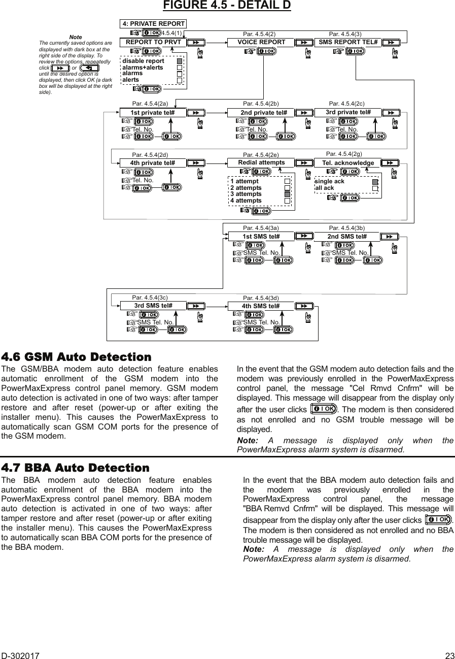
![D-302017 19 GSM/GPRS [Fig 4.5.3(20b)] Here you determine if the GSM/GPRS line disconnection will be reported or not and determine the delay between detection of line disconnection and report failure. If the telephone line is disconnected, the message "GSM line fail" will be stored in the event log. The options are: don't report, 2 minutes, 5 minutes, 15 minutes, or 30 minutes. PSTN Up / Down [Fig 4.5.3(21)] Remote Access [Fig 4.5.3(21a)] Here you give or deny permission to access the system and exercise control from a remote telephone. The options are: rem. access ON and rem. access OFF. Mast. Downl Code [Fig 4.5.3(21b)] Here you determine the master installer 4-digit password for downloading/uploading data into/from the PowerMaxExpress memory. Attention! If "0000" is used, it will not enable connection of the PowerMaxExpress to the PC for upload/download purpose. Inst. Downl Code [Fig 4.5.3(21c)] Here you determine the installer 4-digit password for downloading data into the PowerMaxExpress memory. Attention! If "0000" is used, it will not enable connection of the PowerMaxExpress to the PC for upload/download purpose. Upload Option [Fig 4.5.3(21d)] Here you determine whether the PowerMaxExpress data can be uploaded into a computer while the system is in disarm state or at any time (in HOME/AWAY arming & disarm state). The options are: when system OFF and any time Up Download Tel# [Fig 4.5.3(21e)] Here you enter the telephone number (up to 16 digits) of the UL/DL server. Note: Only for use with control panels monitored by compatible central stations. Leave empty if not used. GPRS Up / Down [Fig 4.5.3(22)] My SIM Tel. # [Fig 4.5.3(22a)] Here you enter the PowerMax SIM card telephone number. The central station dials this number when it needs to connect to the PowerMaxExpress for uploading / downloading data. 1st Caller ID# [Fig 4.5.3(22b)] Here you determine the 1st VDNS receiver telephone number. When the PowerMaxExpress responds to an incoming call from the telephone number defined here, it creates a connection to the VDNS for uploading / downloading data. Note: Caller ID#1 / ID#2 should be 6 or more digits for wake-up by VDNS to work. 2nd Caller ID# [Fig 4.5.3(22c)] Here you determine the 2nd VDNS receiver telephone number. When the PowerMaxExpress responds to an incoming call from the telephone number defined here, it creates a connection to that VDNS for uploading / downloading data. Report Cnfrm Alarm [Fig 4.5.3(24)] - see note in Fig. 4.5 Detail C Here you determine whether the system will report whenever 2 or more events (confirmed alarm) occur during a specific period (see par. 4.4.33). Available options are: enable report, disable report, enable + bypass (enabling report and bypassing the detector - applicable to PowerMaxExpress that is compatible with DD243 standard). Report 24H Zones [Fig 4.5.3(25)] Here you determine whether 24 hour (silent and audible) zones will function as normal 24 hour zones or as panic zones. The options are: both original, audible as panic, silent as panic, or both as panic. Recent Close [Fig 4.5.3(26)] Here you enable or disable the “recent closing” report, that is sent to the central station if an alarm occurs within 2 minutes from the expiry of the exit delay. The options are: recent close ON and recent close OFF. Zone restore [Fig 4.5.3(27)] Here you determine whether a zone restore will be reported or not. The options are: report restore and don't report. System Inactivity Report [Fig 4.5.3(28)] Here you determine whether the central station will receive a message if the system is inactive (not armed) during a defined period (days). The options are: disable, rep. after 7d, rep. after 14d, rep. after 30d, rep. after 90d. 4.5.4 Private Report (Fig. 4.5 Detail D) Report To Private [Fig 4.5.4(1)] Here you determine which event groups will be reported to private telephone subscribers. The options are as follows: • Alarms + alerts • Alarms • Alerts • Disable report The following siren signal will be sent to private telephone upon event reporting: FIRE: ON - ON - ON - pause.... (- - - - - - ......). BURGLAR: ON continuously ( ...) EMERGENCY: 2-tone siren; like an ambulance. Voice report [Fig 4.5.4(2)] 1st Private Tel# [Fig 4.5.4(2a)] Here you program the 1st telephone number (including area code, if required) of the private subscriber to which the system will report the event groups defined in Report To Private. 2nd Private Tel# [Fig 4.5.4(2b)] Here you program the 2nd telephone number (including area code, if required) of the private subscriber to which the system will report the event groups defined in Report To Private. 3rd Private Tel# [Fig 4.5.4(2c)] Here you program the 3rd telephone number (including area code, if required) of the private subscriber to which the system will report the event groups defined in Report To Private. 4th Private Tel# [Fig 4.5.4(2d)] Here you program the 4th telephone number (including area code, if required) of the private subscriber to which the system will report the event groups defined in Report To Private. Redial Attempts [Fig 4.5.4(2e)] Here you determine the number of times the communicator will dial the called party’s number (private telephone). The options are: 1, 2, 3 and 4 attempts. Attention! A maximum of 2 dialing attempts is permitted by the Australian Telecommunication Authority. Tel. acknowledge [Fig 4.5.4(2g)] Here you determine whether the system will use the single acknowledge or the all acknowledge mode when reporting to private telephones.](https://usermanual.wiki/Visonic/PMEXPRESS.Users-Manual-1/User-Guide-1120410-Page-19.png)
![20 D-302017 Note: In the single acknowledge mode, receiving an acknowledge signal from a single telephone is sufficient to consider the current event closed and call off the communication session. The remaining telephones serve for backup purposes only. In the all acknowledge mode, an acknowledge signal must be received from each telephone before the current event is considered reported. The options are: single ack and all ack. SMS Report Tel# [Fig 4.5.4(3)] 1st SMS Tel# [Fig 4.5.4(3a)] Here you define the first SMS phone number (including area code, 16 digits maximum) to which pre-selected event types (see par. 4.6.3) will be reported. 2nd SMS Tel# [Fig 4.5.4(3b)] Here you define the second SMS phone number (including area code, 16 digits maximum) to which pre-selected event types (see par. 4.6.3) will be reported. 3rd SMS Tel# [Fig 4.5.4(3c)] Here you define the third SMS phone number (including area code, 16 digits maximum) to which pre-selected event types (see par. 4.6.3) will be reported. 4th SMS Tel# [Fig 4.5.4(3d)] Here you define the fourth SMS phone number (including area code, 16 digits maximum) to which pre-selected event types (see par. 4.6.3) will be reported. 5. DEFINE COMM.4. DEFINE PANEL3. DEFINE ZONES2. ENROLLING1. NEW INSTL CODEENTER CODEINSTALLER MODEUSER SETTING[installer code]<OK> TO EXIT1: PSTN / GSM2: GPRS / BB3: C.S. REPORTING4: PRIVATE REPORTsee detail Asee detail Bsee detail Csee detail DRefer to Figure 4.1ato gain access toUSER SETTINGSmenu Figure 4.5 – Defining Communications FIGURE 4.5 - DETAIL A1: PSTN / GSMLINE PREFIX DIAL METHOD GSM KEEP ALIVEAREA CODEdisableevery 28 daysxxxx(Enter prefix)xxxx(Enter tel. area code)4.5.1(1) Par. 4.5.1(2) Par. 4.5.1(3) Par. 4.5.1(4)tone (dtmf)pulseNoteThe currently saved options aredisplayed with dark box at theright side of the display. Toreview the options, repeatedlyclick oruntil the desired option isdisplayed, then click OK (a darkbox will be displayed at the rightside). FIGURE 4.5 - DETAIL B2: GPRS/BBGPRS REPORT GPRS APNGPRS USERNAME GPRS PASSWORDdisableenabledisableenabledisableenableGSM REPORT SMS REPORT4.5.2(1) Par. 4.5.2(2) Par. 4.5.2(3) Par. 4.5.2(4)Par. 4.5.2(5) Par. 4.5.2(6)(Enter GPRSusername)xxxx...(up to 40 digits)(Enter name of APN)(Enter GPRSpassword)xxxx...(up to 30 digits) xxxx...(up to 16 digits)NoteThe currently saved options aredisplayed with dark box at theright side of the display. Toreview the options, repeatedlyclick oruntil the desired option isdisplayed, then click OK (a darkbox will be displayed at the rightside).SIM PIN CODE(Enter SIM cardPIN code)Par. 4.5.2(8)xxxx...(up to 16 digits)FORCE HOME NETW.disableenablePar. 4.5.2(9)](https://usermanual.wiki/Visonic/PMEXPRESS.Users-Manual-1/User-Guide-1120410-Page-20.png)
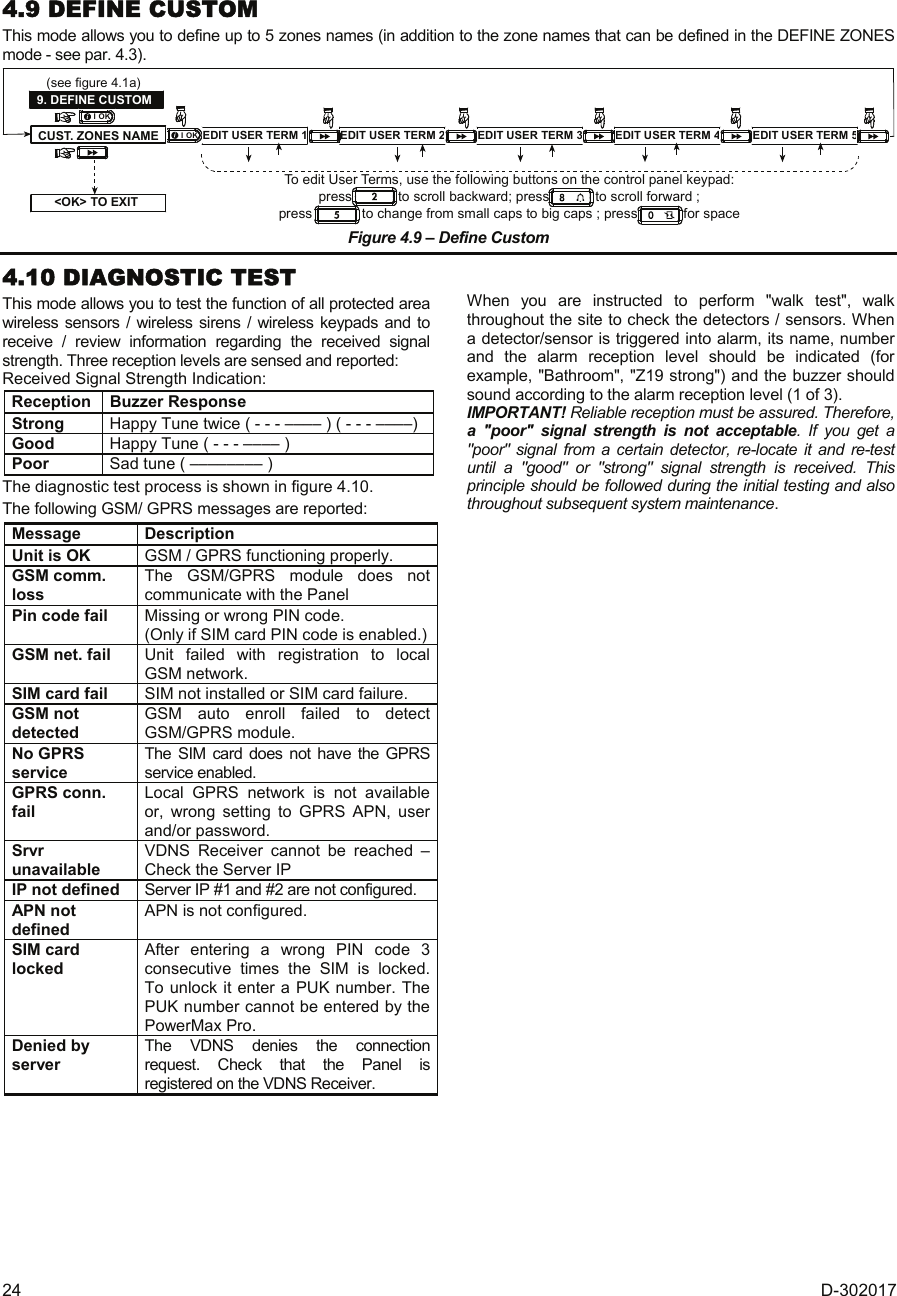
![D-302017 25 (Perform walk test)BATHROOMDIAG. TESTINGFRONT DOORZ1 POORZ19 STRONG(alternating for 5 sec.)LIVING ROOMZ2 OK(alternating for 5 sec.) Exampleof testresultdisplay (Each time the OK button is pressed,the next test result is displayed)(see figure 4.1a) Exampleof testresultdisplay Exampleof testresultdisplayDIAG. TESTINGWL SENSORS TESTS1 CPUWL SIRENS TESTS1 CPU=STRONGWAITS2 CPUPLEASE WAIT...S2 CPU=STRONGWL KEYPADS TESTK1 CPUK1 CPU=STRONGWAITK2 CPUPLEASE WAIT...K2 CPU=STRONGNoteSTRONG/GOOD/POOR/“NOT OK” (with siren No.,S1 or S2 before) isdisplayed according to thewireless siren signalstrength).S1=siren 1. S2 = siren 2.CPU = Control Panel Unit = 2 way comm.NoteSTRONG/GOOD/POOR/“NOT OK” (with keypadNo., K1 or K2 before) isdisplayed according to thewireless siren signalstrength).K1=keypad1 K2=keypad2CPU = Control Panel Unit = 2 way comm.NON-PARTITIONING ONLYGPRS CONN. TEST LAN CONNECT. TEST10. DIAGNOSTICSPLEASE WAIT... PLEASE WAIT...UNIT IS OK UNIT IS OK*( ) *( )When the OK button is pressed, the test result takesbetween 15 sec. to 4 mins. before it is displayed,depending on the severity of the failure.See par. 4.10 for a complete list of possibleGSM/GPRS messages.*( ) Figure 4.10 - Diagnostic Test Flow Chart 4.11 USER FUNCTIONS This mode provides you with a gateway to the user functions through the regular user programming menu. You may: • Program the 4 (private) telephone numbers • Program user codes • Enroll keyfobs • Set the auto arm option • Set arming time • Set the squawk option • Set the system time and time format • Set the date and date format Refer to the User Guide for detailed procedures. Caution! If after having programmed the user codes the system does not recognize your installer code, this indicates you must have programmed a user code that is identical with your installer code. If so, access the user menu and change the code that is identical with your installer code. This will re-validate your installer code. 4.12 RETRIEVING FACTORY DEFAULTS If you want to reset the PowerMaxExpress parameters to the factory default parameters, you should enter the installer menu and perform the "FACTORY DEFLT" function, as described in the right side illustration. To get the relevant parameters defaults, contact the PowerMaxExpress dealer. Note: For PowerMaxExpress with 2 installer codes, INSTALLER code and MASTER INSTALLER code, only the master installer code enables to perform factory default function. 12. FACTORY DEFLT[installer code]<OK> to restoreENTER CODE:PLEASE WAIT ...Entering to/exit from the FACTORYDEFLT menu is shown in figure 4.1aThis is a brief display after which allthe factory defaults are retrieved. 4.13 SERIAL NUMBER The menu "13. SERIAL NUMBER" enables reading the system serial number and panel ID for support purposes only. Panel ID is a unique number of the control panel that is used for registering the PowerMaxExpress to VDNS when using GPRS. 4.14 CALLING UPLOAD/DOWNLOAD SERVER Note: This option is only used during the installation of panels monitored by compatible central stations. This option allows the installer to initiate a call to the upload/download server. The server uploads the PowerMaxExpress configuration to its data base and can unload predefined parameters to the PowerMaxExpress .](https://usermanual.wiki/Visonic/PMEXPRESS.Users-Manual-1/User-Guide-1120410-Page-25.png)
![26 D-302017 USER SETTINGSENTER CODE1. NEW INSTL CODE2. ENROLLING3. DEFINE ZONES5. DEFINE COMM[installer code]INSTALLER MODE4. DEFINE PANELCOMMUNICATING TEL # NOT DEFINEDDOWNLOADING DIAL ATTEMPT FAILDOWNLOAD OK DOWNLOAD FAILEDDisplayed duringdialing processDisplayed for halfa minute approx.accompanied by sad(failure) melodyIf UL/DL servertel. # was notdefined before(see par. 4.5.34)If UL/DL servertel. # is alreadydefined (seepar. 4.5.34)DialingOK DialingfailedDownloadOK DownloadfailedDisplayed duringdownload processDisplayed for halfa minute approx.accompanied by sad(failure) melodyDisplayed for halfa minute approx.accompanied by sad(failure) melodyDisplayed for halfa minute approx.accompanied by happy(success) melody9. DEFINE CUSTOM10. DIAGNOSTICS11. USER SETTINGS12. FACTORY DEFLT13. SERIAL NUMBER14. START UL/DL<OK> TO EXITRefer to Figure 4.1ato gain access toUSER SETTINGSmenuREADY 00:00 P1 RDY 00:00Non-Partitionmode Partitionmode Figure 4.14 – Start UL/DL 4.15 ENABLING/DISABLING PARTITIONSThis mode allows you to enable/disable the partitioning feature (optional). Partitioning allows you to divide the system into a maximum of four independently controllable areas. A different user code is assigned to each partition in order to limit or control access to each area. A partition can also be armed or disarmed regardless of the status of the other partitions within the system. When the partition feature is disabled, zones, user codes and features will operate the same as in a regular PowerMaxExpress unit. When partition is enabled, menu displays are changed to incorporate the partition feature. 15. PARTITIONINGUSER SETTINGSENTER CODE1. NEW INSTL CODEINSTALLER MODE[inst. code]<OK> TO EXITenabledisableNote: Partitioning is an optional featureRefer to Figure 4.1ato gain access toUSER SETTINGSmenu Figure 4.15 – Partitioning 4.16 WALK-TESTThis mode (see Figure 4.1a) provides you with the means to conduct a periodic test, via the walk-test menu, at least once a week and after an alarm event.](https://usermanual.wiki/Visonic/PMEXPRESS.Users-Manual-1/User-Guide-1120410-Page-26.png)