Visonic PWRMAXPLUS Alarm System Control Panel User Manual DE5467U0 W2002
Visonic Inc. Alarm System Control Panel DE5467U0 W2002
UserManual.wiki
>
Visonic
>
PWRMAXPLUS User Manual
>
Users Manual
Contents
1.
Installation Instructions
2.
Users Manual
Users Manual
Navigation menu
Upload a User Manual
Namespaces
Wiki Guide
HTML
PDF
Info
Views
User Manual
Discussion / Help
Navigation
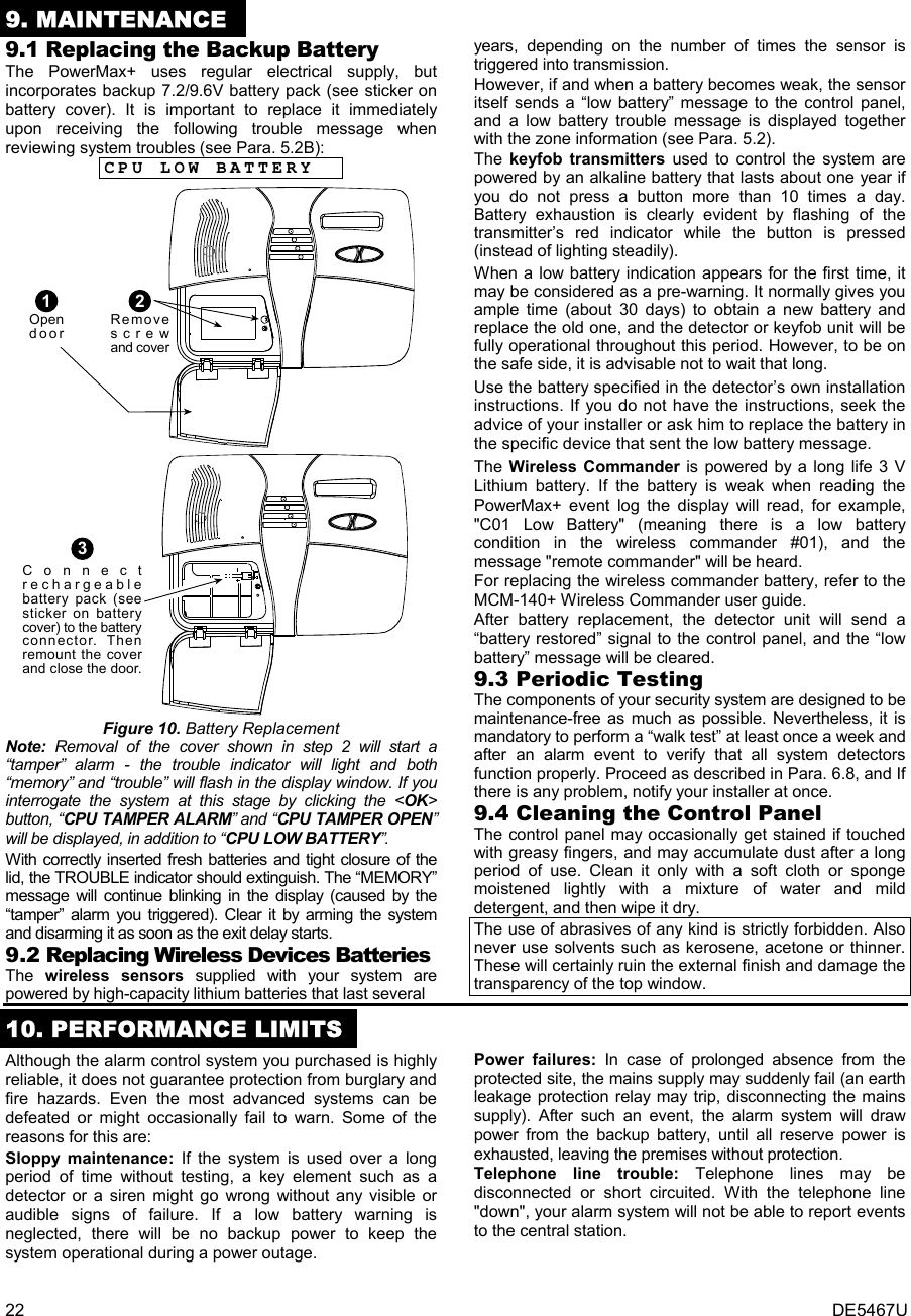
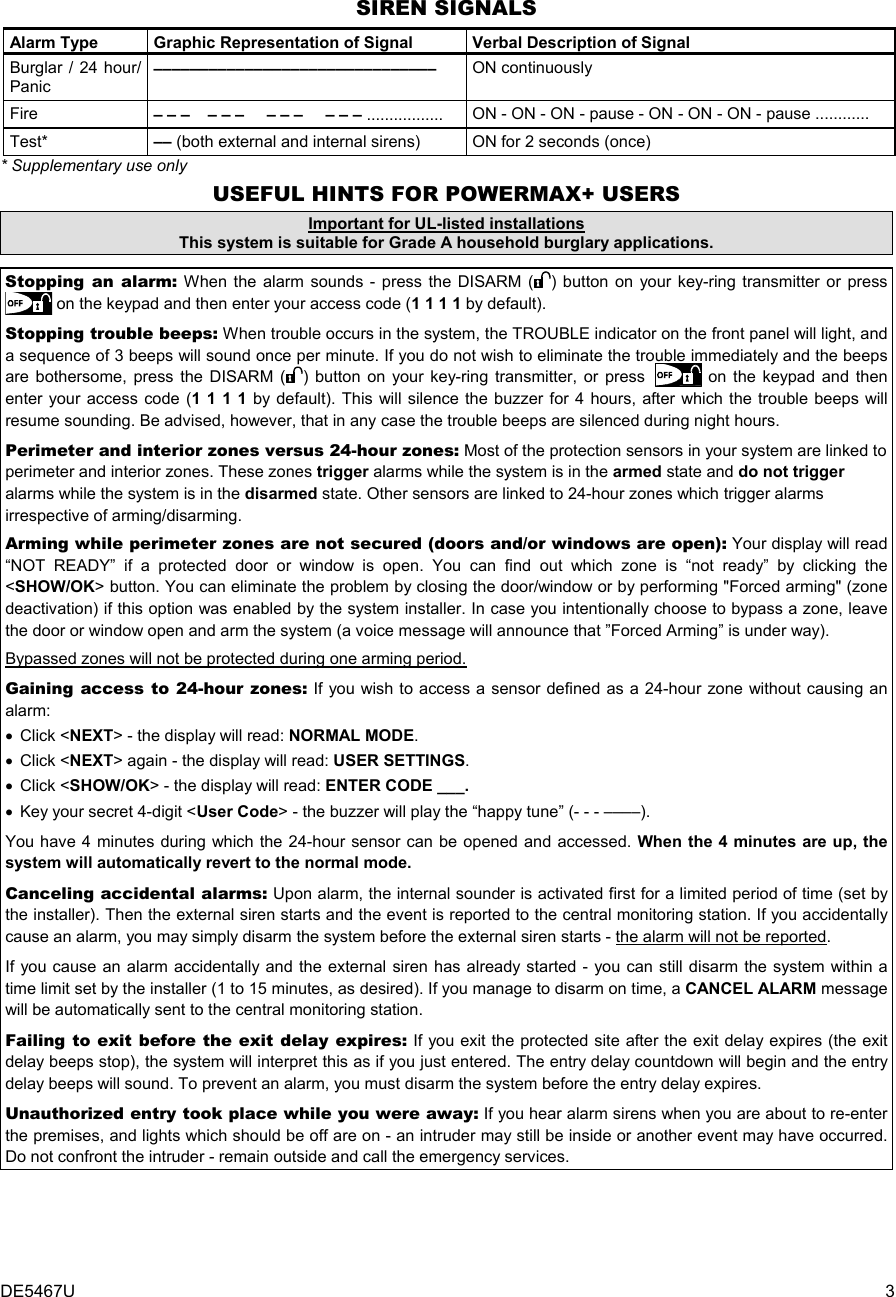
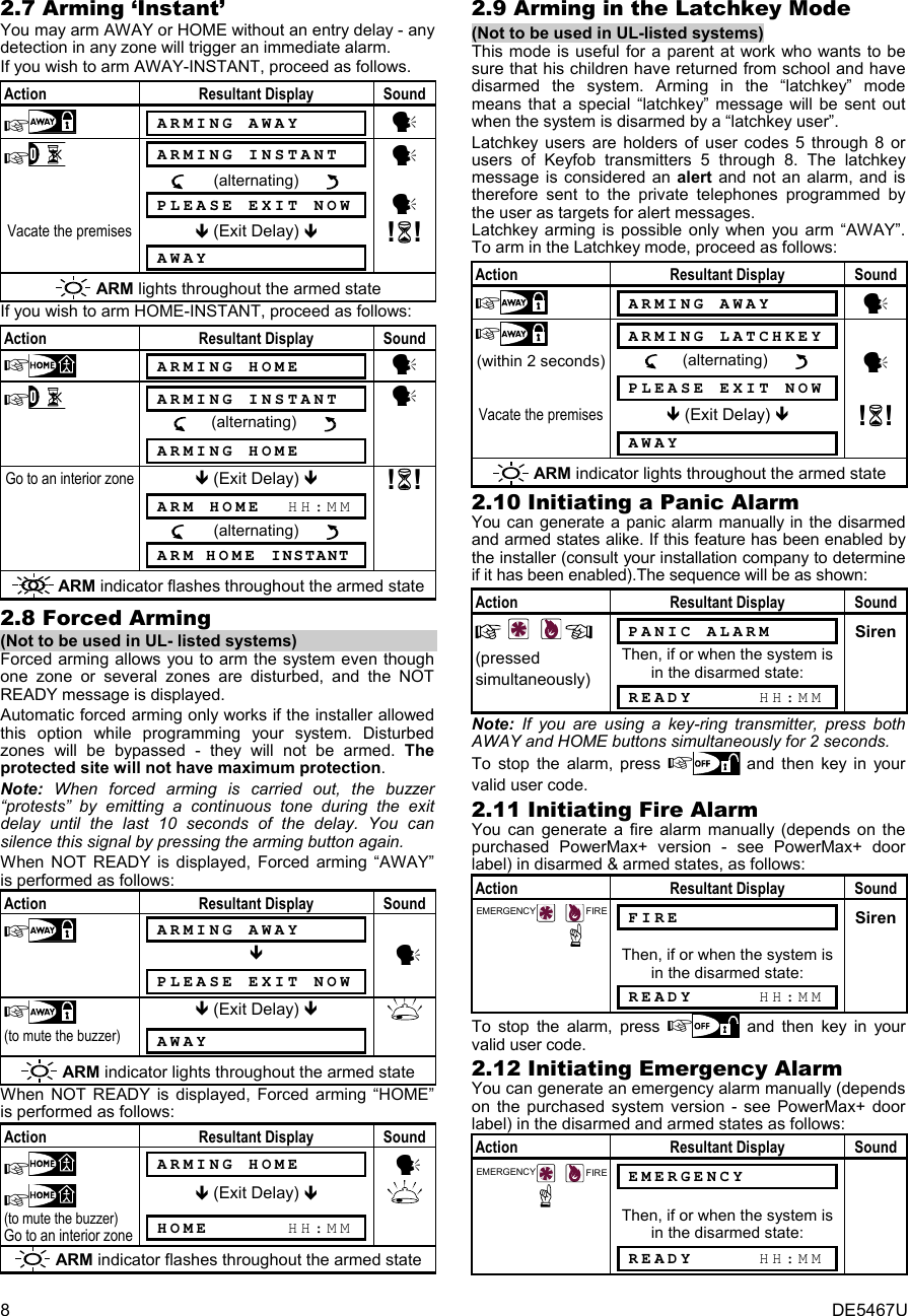
![DE5467U 1 POWERMAX+ Fully Supervised Wireless Alarm Control System User’s Guide TABLE OF CONTENTS 1. INTRODUCTION..............................................................4 1.1 Overview ..................................................................4 1.2 System Features......................................................5 1.3 Terms of the Trade ..................................................5 1.4 Symbols Used in This Manual..................................5 1.5 Control Pushbuttons ................................................5 1.6 Multi-Function Transmitter .......................................5 1.7 Voice Announcements .............................................6 1.8 Screen Saver Option................................................7 2. SECURING THE PROTECTED SITE .............................7 2.1 Security-Related Pushbuttons..................................7 2.2 Preparing to Arm......................................................7 2.3 Arming ‘AWAY’.........................................................7 2.4 Arming ‘HOME’ ........................................................7 2.5 Switching from ‘HOME’ to ‘AWAY’ ...........................7 2.6 Switching from ‘AWAY’ to ‘HOME’ ...........................7 2.7 Arming ‘Instant’ ........................................................8 2.8 Forced Arming .........................................................8 2.9 Arming in the ‘Latchkey’ Mode.................................8 2.10 Initiating a Panic Alarm ............................................8 2.11 Initiating Fire Alarm ..................................................8 2.12 Initiating Emergency Alarm ......................................8 2.13 Disarming and Stopping Alarms...............................9 2.14 Siren Behavior..........................................................9 3. SPEECH AND SOUND CONTROL .................................9 3.1 Speech and Sound Control Pushbuttons.................9 3.2 Adjusting the Speech Volume..................................9 3.3 Voice ON/OFF........................................................10 3.4 Recording a Message ............................................10 3.5 Message Playback.................................................10 3.6 Chime ON/OFF ......................................................10 4. ELECTRICAL APPLIANCE CONTROL.........................10 4.1 Control Options and Pushbuttons .........................10 4.2 Manual Switch-On.................................................10 4.3 Manual Switch-Off.................................................11 4.4 Light DIM/BRIGHT ................................................11 4.5 Automatic ON/OFF Control ...................................11 5. READING ALARM MEMORY & TROUBLE DATA.........11 5.1 Reviewing Alarm / Tamper Memory .......................11 5.2 Reviewing Trouble Information ..............................12 5.3 Reviewing Memory & Troubles at the Same Time.12 5.4 Correcting Trouble Situations ................................12 6. SPECIAL FUNCTIONS..................................................13 6.1 Looking after People Left at Home ........................13 6.2 Emergency Calls for Help ......................................13 6.3 Remote Control by Telephone...............................13 6.4 Reporting to Private Telephone .............................14 6.5 Remote Control by SMS ........................................14 6.6 Reporting by SMS..................................................15 6.7 Reporting Messages to a Pager ............................15 6.8 Conducting a Walk Test.........................................15 7. USER SETTINGS ..........................................................15 7.1 What are the Settings You Need? .........................15 7.2 Entering the User Settings Menu...........................16 7.3 Bypassing Zones ...................................................16 7.4 Reviewing the Bypassed Zone List........................17 7.5 Recalling the Last Bypass Scheme .......................17 7.6 Programming Four Telephone Numbers ...............17 7.7 Setting the User Codes..........................................17 7.8 Enrolling Keyfob Transmitters......................................19 7.9 Deleting Keyfob......................................................19 7.10 Setting the Voice Options ......................................19 7.11 Automatic Arming Option.......................................20 7.12 Setting Arming Time ..............................................20 7.13 Enabling the Squawk Option..................................20 7.14 Setting Time and Time Format ..............................20 7.15 Setting the Date and Date Format .........................21 7.16 Scheduler Function................................................21 7.17 Installer Mode ........................................................21 8. READING THE EVENT LOG.........................................21 8. 1 Event Log Description............................................21 8. 2 Reading Procedure................................................21 9. MAINTENANCE.............................................................22 9.1 Replacing the Backup Battery................................22 9.2 Replacing Wireless Devices Batteries ...................22 9.3 Periodic Testing .....................................................22 9.4 Cleaning the Control Panel....................................22 10. PERFORMANCE LIMITS .............................................22 APPENDIX A. GLOSSARY .................................................23 FCC Statements.................................................................24 QUICK REFERENCE TO PRIMARY ALARM CONTROL OPERATIONS Arming AWAY ................................................................ + [Code]* Arming AWAY-INSTANT ................................................ + [Code]* + Arming HOME ................................................................ + [Code]* Arming HOME-INSTANT ............................................... + [Code]* + Arming AWAY-LATCHKEY ........................................... + [Code]* + Force Arming AWAY (system not ready) ....................... + [Code]* + (to silence the protest buzz) Force Arming HOME (system not ready) ....................... + [Code]* + (to silence the protest buzz) Disarming and stopping alarms ................................... + [Code] * The factory default master user code is 1 1 1 1. The code is not required if quick arming has been permitted by the installer. Change the factory default code to a secret code without delay (see Para. 7.7)](https://usermanual.wiki/Visonic/PWRMAXPLUS.Users-Manual/User-Guide-408682-Page-1.png)
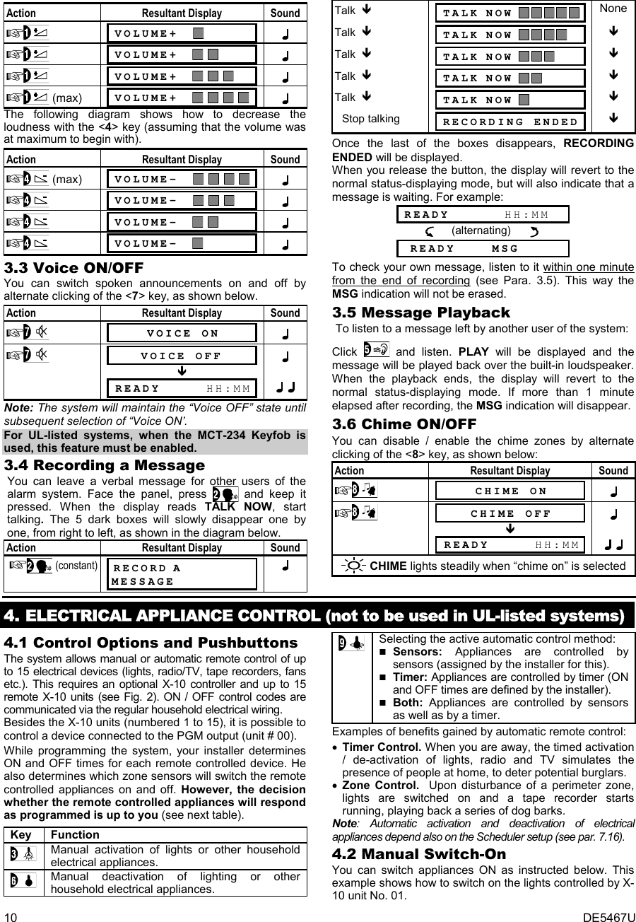
![DE5467U 7 1.8 Screen Saver Option The Screen Saver option (if enabled by the installer) causes that when no key is pressed during more than 30 seconds, the display is “PowerMax” and the LEDs do not light (to prevent an intruder to know the system status). The normal display returns after pressing the OFF button followed by entering user code (Refresh by Code) or after pressing any key (Refresh by Key), as selected by the installer. If Refresh by Key was selected, the first pressing of any key (except Fire and Emergency) causes normal display return and the second press performs the key function. Regarding the Fire and Emergency keys, the first key press causes normal display return and also performs the Fire/Emergency function. 2. SECURING THE PROTECTED SITE 2.1. Security-Related Pushbuttons Key Function Arming when nobody is at home Arming when people remain at home Canceling the entry delay upon arming (‘AWAY-INSTANT’ or ‘HOME-INSTANT’) Disarming the system and stopping alarms Testing the system (see Para. 6.8). 2.2 Preparing to Arm Before arming, make sure that READY is displayed: READY HH:MM If Ready is displayed, all zones are secured, and you may arm the system any way you choose. If at least one zone is open (disturbed), the display will read: NOT READY HH:MM If NOT READY is displayed because of unsecured zone, click to review the numbers and names of all open zones one by one. Let us assume that zone 2 (the back door) and zone 13 (the kitchen) are open. To investigate, proceed as follows: Action Resultant Display Sound NOT READY HH:MM y BACK DOOR (alternating) y Z2 OPEN Kitchen (alternating) y Z13 OPEN None (see note (after 10 seconds) below) NOT READY HH:MM Note: To quit immediately at any stage, press . It is highly recommended to fix the open zone(s), thus restoring the system to the state of “ready to arm”. If you do not know how to do this, consult your installer. IMPORTANT! All arming procedures below are based on the assumption that quick arming has been enabled by the installer. If quick arming is disabled, the PowerMax+ will prompt you to enter your security code before arming. 2.3 Arming ‘AWAY’ If the system is READY, proceed as shown: Action Resultant Display Sound ARMING AWAY y PLEASE EXIT NOW y Vacate the premises (Exit Delay) !! AWAY ARM lights steadily throughout the armed state 2.4 Arming ‘HOME’ If all perimeter zones are READY, and quick arming is allowed, proceed as shown: Action Resultant Display Sound ARMING HOME y Move to interior zone (Exit Delay) !! HOME HH:MM ARM flashes throughout the armed state 2.5 Switching from ‘HOME’ to ‘AWAY’ Do not disarm the system - just press . The response will be the same as in Para. 2.2. Vacate the premises before the exit delay expires. 2.6 Switching from ‘AWAY’ to ‘HOME’ Do not disarm the system - just press . Since this operation reduces the security level, the PowerMax+ will ask you to key in your master user code or user code, thus making sure that you are an authorized user. Action Resultant Display Sound ENTER CODE ___ y [³] ARMING HOME y Move to interior zone (Exit Delay) !! ARM HOME HH:MM ARM flashes throughout the armed state If an alarm occurred while the system was armed in the AWAY mode, the display will respond differently: Action Resultant Display Sound ENTER CODE ___ y [³] ARMING HOME y Move to interior zone (Exit Delay) !! HOME HH:MM (alternating) ARM HOME MEMORY ARM flashes throughout the armed state](https://usermanual.wiki/Visonic/PWRMAXPLUS.Users-Manual/User-Guide-408682-Page-7.png)
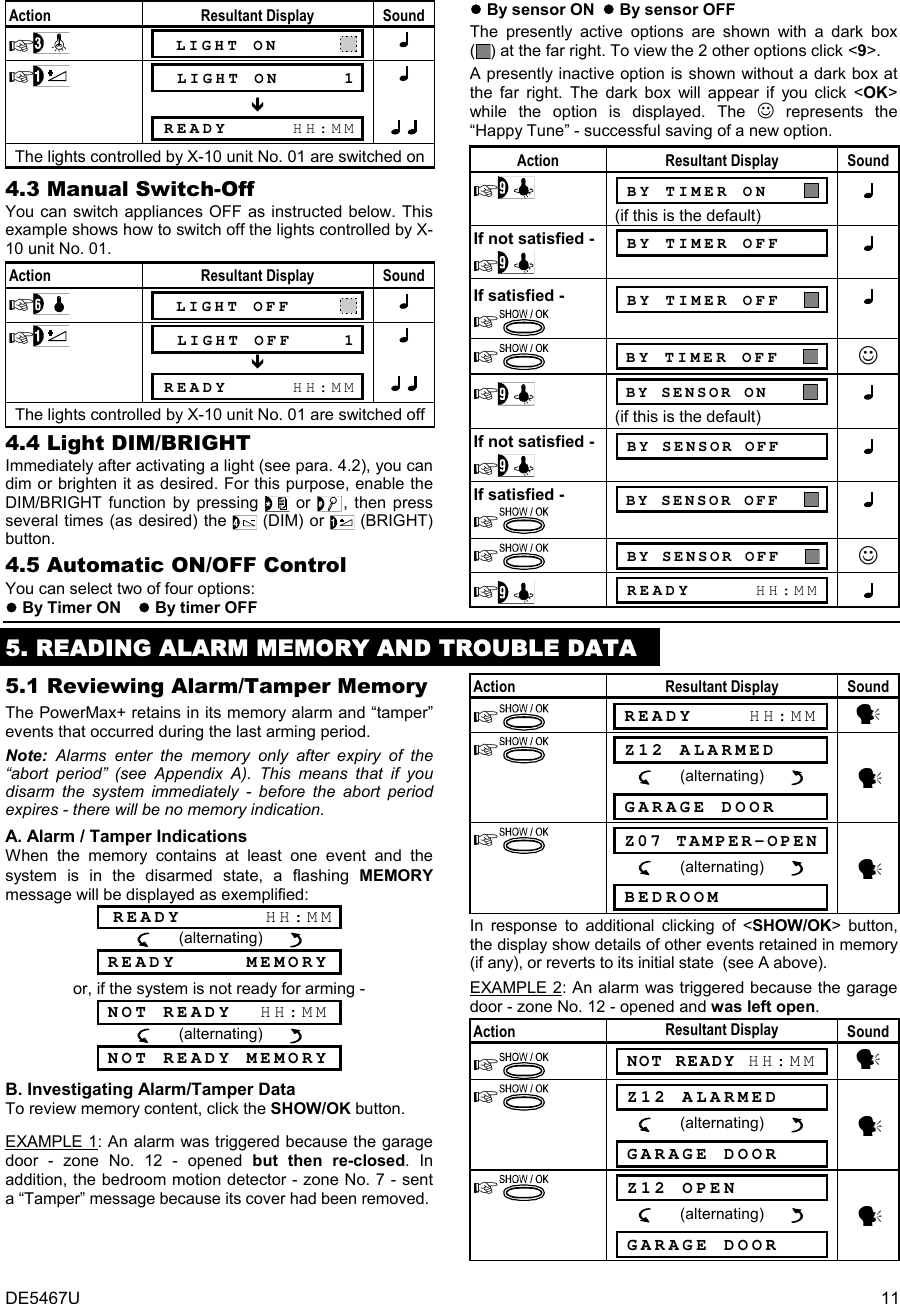
![DE5467U 9 To stop the alarm, press and then key in your valid user code. 2.13 Disarming and Stopping Alarms Disarming the system stops the siren before it stops automatically, irrespective of whether the alarm was initiated in the armed or the disarmed state. After disarming, different displays may appear, depending on the current status of the system: A. Disarming - no events: After an uneventful armed term, the disarming operation will progress as shown: Action Resultant Display Sound CODE ___ y [³] READY HH:MM ☺ y ARM indicator extinguishes B. Disarming after alarm, with all zones ready: If the zone that alarmed in the armed state is back to normal, the disarming operation will progress as shown: Action Resultant Display Sound CODE ___ y [³] READY HH:MM (alternating) READY MEMORY ☺ y ARM indicator extinguishes To read the alarm memory, refer to Section 5. The "MEMORY" message will disappear only upon re- arming the system. C. Disarming after an alarm, with one zone still disturbed: If the zone that alarmed in the armed state is still disturbed, the disarming operation will progress as shown in the following table. Action Resultant Display Sound CODE ___ y [³] NOT READY HH:MM (alternating) NOT READY MEMORY ☺ y ARM indicator extinguishes To read the alarm memory, refer to Section 5. The "MEMORY" message will disappear only when you rearm the system. If you do not know how to return the disturbed zone to normal, consult your installer. D. Disarming with the system in a state of trouble. If trouble is detected in the armed state, the TROUBLE indicator on the front panel will light and the disarming operation will progress as shown: Action Resultant Display Sound CODE ___ y [³] READY HH:MM (alternating) READY TRBL ☺ y ARM extinguishes and sounds once per minute To find out what kind of trouble is being sensed, see Section 5. The TRBL display will disappear, the TROUBLE indicator will extinguish and the trouble beeps will stop upon eliminating the cause for trouble. E. Disarming after an alarm, with the system in a state of trouble. The TROUBLE indicator on the front panel will light. If the zone that alarmed while the system was in the armed state is back to normal, the disarming operation will progress as shown: Action Resultant Display Sound CODE ___ y [³] READY HH:MM (alternating) READY TRBL (alternating) READY MEMORY ☺ y ARM extinguishes and sounds once per minuteTo find out which zone alarmed and what kind of trouble is being sensed, see Section 5. The TRBL display will disappear, the TROUBLE indicator will extinguish and the trouble beeps will stop upon eliminating the cause for trouble. The MEMORY message will disappear only upon rearming the system. F. Disarming under Duress. If you are forcibly compelled to disarm the system, enter the default duress code (2580) or another code set by the installer. Disarming will take place normally but a silent alarm will be transmitted to the central station. 2.14 Siren Behavior Continuously ON when initiated by a burglar zone or a 24-hour zone, and when a user initiates a “panic alarm”. When initiated by a fire zone (smoke is detected) ON - ON - ON - pause - ON - ON - ON - pause - ........ and so on. If there is nobody around to disarm the system upon alarm and a zone remains "open", the siren will sound for the time duration set by the installer - then will stop. The strobe light keeps flashing until the system is disarmed. 3. SPEECH AND SOUND CONTROL 3.1 Speech & Sound Cont. Push-buttons The sound and speech-related functions offered by the PowerMax+ are controlled with the keypad, as detailed in the following list. Key Function Increasing the loudness of spoken messages Decreasing the loudness of spoken messages disabling the loudspeaker Recording a spoken message for other users of the alarm system Listening to a recorded message left by another user of the alarm system Enabling / disabling the chime function in chime zones 3.2 Adjusting the Speech Volume The following diagram shows how to increase the loudness by clicking the <1> key (assuming that the volume was at minimum to begin with).](https://usermanual.wiki/Visonic/PWRMAXPLUS.Users-Manual/User-Guide-408682-Page-9.png)
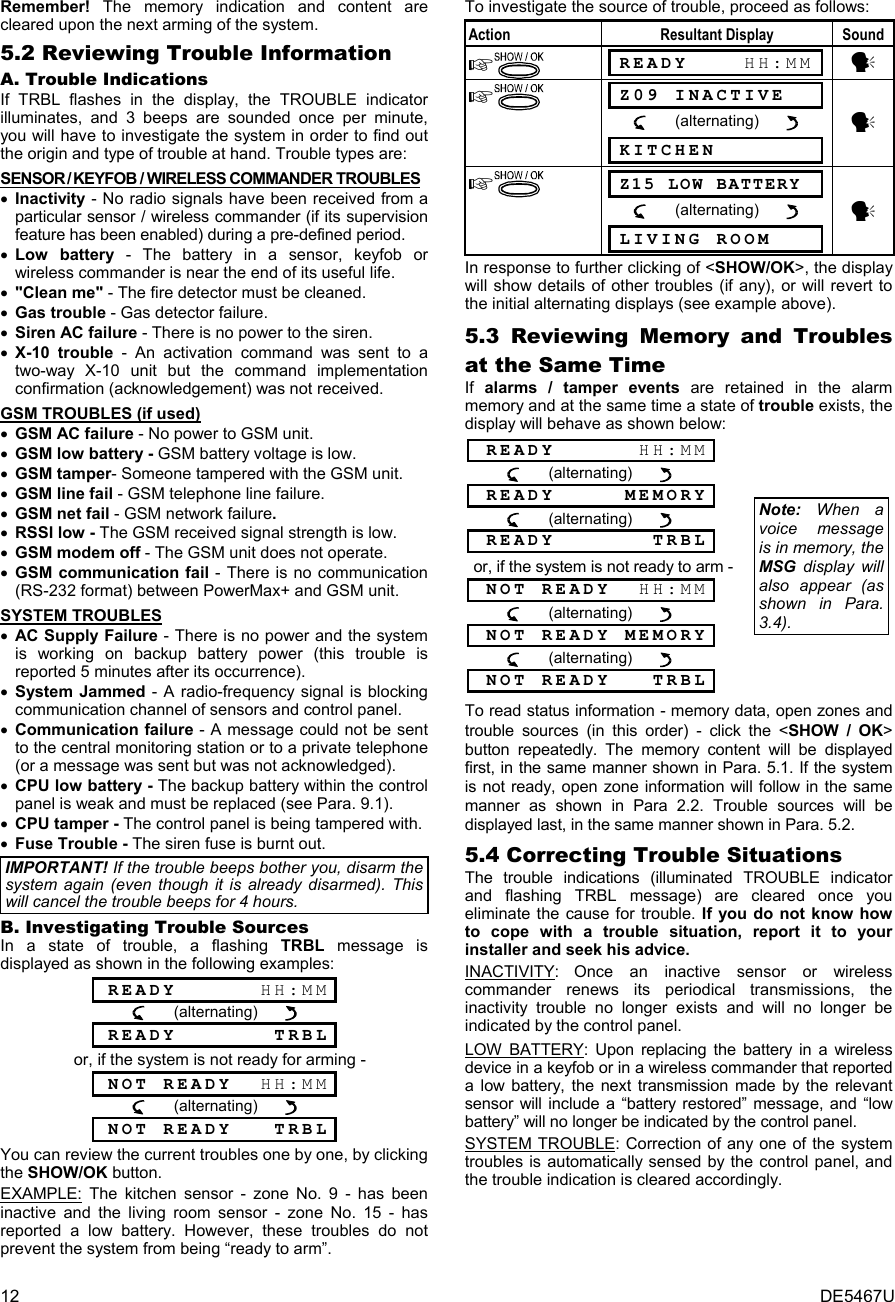
![DE5467U 13 6. SPECIAL FUNCTIONS 6.1 Looking after People Left at Home An important characteristic of the PowerMax+ is its ability to function in a mode contrary to the usual behavior of an alarm system. When the system is in the disarmed state (or even when armed “HOME” with perimeter protection only), it can keep track of in-house activity and will report lack of motion in interior zones if there is no detection of motion within predetermined time limits. To use this characteristic, you must ask your installer to program a specific time limit beyond which lack of motion will be reported as a “not active” alert. To make things clear, let us assume that an elderly, sick or handicapped person is left unattended in a protected site. This person, disabled or sick as he may be, will not stay entirely still for hours. It is only natural that even while being asleep he will turn over in his bed from time to time. He might also wander into the kitchen to eat or drink, or to the bathroom for other necessities. Upon doing so, the bedroom, bathroom and kitchen motion detectors will detect his movement. If, for example, the “lack of motion” time limit is set by your installer to 6 hours, a virtual 6-hour clock will carry out a 6-hour “countdown”. If motion is detected within the 6-hour time frame, the countdown will restart from the beginning (the virtual 6-hour clock will be “reset”) and no alert message will be sent out. If no motion is detected within the 6-hour time frame in any interior zone, the control panel will send a “not-active” alert message to the central monitoring station or to private telephones designated by the installer. IMPORTANT! In addition, you may provide the person confined to interiors with a single-button transmitter for distress situations - see Para. 6.2. 6.2 Emergency Calls for Help (not to be used in UL-listed systems) Suppose the disabled person discussed in Para. 6.1 above has an accident such as falling in the bathtub without being able to get up. It might take hours before the “No Active” alert is sent out, but he (or she) must be assisted much sooner. Even though the odds for such an accident are not high, it is advisable to provide the disabled person with a miniature, single-button pendant-type or wristwatch-type transmitter. Pressing the button on this transmitter will cause the PowerMax+ to send an “emergency call” to the central monitoring station or to private telephones designated by the installer. To make this possible, ask your installer to define one of the 28 zones of the PowerMax+ as an emergency zone. Then, obtain one of the transmitters listed below and link this transmitter’s ID code to the emergency zone. Compatible distress transmitters are (see Fig. 5): MCT-201 - pendant-type (not listed by UL) MCT-211 - wristwatch-type (not listed by UL) MCT-101 - pocket-type (not listed by UL) MCT-201 MCT-211 MCT-101 Figure 5. Single-button Emergency Transmitters 6.3 Remote Control by Telephone PowerMax+controlpanel A. Establishing Telephone Communication You can access the PowerMax+ system from a remote telephone and perform arming and disarming, activation and deactivation of electrical devices and the auxiliary output (PGM), record, playback and erase a voice message, and investigate the system status. The process is shown in the next illustration. 1. Dial the PowerMax+ tel. No. 2. Wait for 2-4 rings then hang up. 3. Wait 12-30 sec. 4. Redial PowerMax+ tel. No. (Sound will be heard for 10 sec.) Not applicable when dialing to the GSM number of the PowerMax+. Proceed to step 5. 5. [*} (to stop the sound) 1 6. [user code], [#] 2 7. [Desired command, see next table] 3 Notes (1) The PowerMax+ responds in a similar way if you just dial once and wait until you hear telephone rings (in USA, for example, 11 rings). (2) Entering of user code is required once only. (3) If you wait more that 50 seconds without keying a command, the PowerMax+ will disconnect the line. B. Executable Commands Command Keying Sequence Disarming [][1][#] Arming Home [][2][#] Arming Home-Instant [][2][1][#] Arming Away [][3][#] Arming Away-Instant [][3][1][#] Arming Away-Latchkey [][4][#] Arming Away-Instant-Latchkey [][4][1][#] Elect. Devices (No. 01-15) ON [][5][device No.][1] [#]Elect. Devices (No. 01-15) OFF [][5][device No.][0] [#]Activating PGM output [][5][0] [0][1][#] Deactivating PGM output [][5][0] [0][0][#] Two-way voice communication (see sub-par. C) [][7][#] Recorded message playback [][8][1] [#] Recorded message start record [][8][2] [#] Recorded message stop record [][8][3] [#] Recorded message erase message [][8][4] [#] Investigating system status [][9][#] Quit (end communication) [][9][9][#] C. Two-Way Voice Communication (Not to be used in UL-listed systems) Perform steps 1-6 in par. 6.3A and continue as follows: 1. [][7][#] 2. Wait for 2 beeps 3. [3] or [1] or [6] (see below) The system will start to function in the "LISTEN IN" mode, letting you hear the sounds within your residence for 50 seconds. If the person under surveillance happens to speak or cry then, you will hear this. You can switch the system to Listen-In, Speak Out or Full Duplex, as shown in the next table.](https://usermanual.wiki/Visonic/PWRMAXPLUS.Users-Manual/User-Guide-408682-Page-13.png)
![14 DE5467U Command Key Listen-in (listening to the person at home) (*) [3] Speak-out (speaking to the person at home) (*) [1] Full-duplex (listening & speaking) (*) [6] Note: To prolong the communication session by 50 seconds, press [3], [1] or [6] again, as required. * The 2-way communication can be terminated by anyone close to the PowerMax+, by disarming the system. Remark Regarding Listen-in & Speak-out modes Listen-in & Speak-out modes allow one way speech at a time. Back and forth exchange of uninterrupted speech between two parties is a method normally used in military, commercial and amateur radio communication. Once you finish talking you should say “Go Ahead” or “Over” and then switch from speak-out to listen in. When the person at home finishes talking he should also say “Over”, as a cue to you to switch back from Listen-in to speak out. EXAMPLE: You (at remote telephone): [1], “Hey, George, can you hear me? Are you in any trouble? Over”.... [3] Person at home: “Yes, I am. I had a dizzy spell while trying to get out of bed and fell on the floor. I am unable to get up and my thigh hurts. Can you help me? Over”... You (at remote telephone): [1], “Sure, I will send someone right away, stay put - over”..... [3]. Person at home: “Thanks, please hurry, over”. You (at remote telephone): [1], “All right, over and out”..... []9][9] (END OF SESSION) Important! If you wish to exit the two-way communication mode and execute another command, just press [] and then key your user code followed by the command (see “keying sequences” in Para. 6.3 B above). 6.4 Reporting to Private Telephone PowerMax+controlpanel The PowerMax+ can be programmed by the installer for selective transmission of messages to private telephone subscribers. Messages are divided by type into 3 groups: Group Events Reported 1 Fire, Burglary, Panic, Tamper 2 Arming AWAY, Arming HOME, Disarming 3 No-activity, Emergency, Latchkey Group 1 has the highest priority and group 3 has the lowest priority. When the called party answers a call initiated by the PowerMax+, he will hear a verbal message composed of the “house identity” and the type of event that occurred. For example, once smoke is detected in the Smith residence, the message will be: [The Smith Residence - Fire Alarm]. If a person under surveillance in the Watkins residence has been inactive, the message will be: [The Watkins Residence - No Activity]. The called party must acknowledge the message (as explained later on), but if he does not respond, the message will be transmitted repeatedly as many times as possible within a 45-second time limit. When the 45 seconds are up, the PowerMax+ will disengage the line and call the next private telephone number on its list. The called party can acknowledge the message by pressing a key on the telephone keypad, as follows. Command KeyAcknowledge only: The PowerMax+ disengages the line and considers the event duly reported. 2 Acknowledge and listen-in: The protected site is “bugged” for sound for 50 seconds. The called party may prolong the listening session by pressing [3] again before the PowerMax+ disengages the line, or by pressing [1] to speak. 3 Acknowledge and speak out: The called party may speak for 50 seconds to whoever is in the protected site. The called party may prolong the “speak out” session by pressing [1] again before the PowerMax+ disengages the line, or by pressing [3] to listen. 1 Acknowledge and 2-way conversation: You and the called party can speak and listen without any necessity to switch the system from "listen-in" to "speak-out" and vice versa for 50 sec. (extendable). 6 Acknowledge and request a status report: The PowerMax+ will issue a verbal report of system status. For example: [Disarm - ready to arm] or [Disarm - back door open] or [Disarm - alarm in memory]. 9 6.5 Remote Control by SMS PowerMax+ system with GSM unit can respond to SMS commands from any cellular telephone, only if the “REM ACCESS ON” command was pre-selected by the system installer. The various SMS commands are detailed in the following table (the detailed SMS message sending process is described in the cellular telephone user’s guide). In this table, “<code>” means 4-digit user code and blank space simply means blank space. SMS Command List Command SMS Format 1Arm AWAY “AWAY <code>” or “AW <code>” 2Arm AWAY instant “AWAY INST <code>” or “AWI <code>” 3Arm AWAY Latchkey “LATCHKEY <code>” or “LK <code>” 4Arm AWAY Latchkey instant“LATCHKEY INST <code>” or “LKI <code>” 5Arm HOME “HOME <code>” or “HM <code>” 6Arm HOME instant “HOME INST <code>” or “HMI <code>” 7Disarm “DISARM <code>” or “DA <code>” 8Turn light xx on (xx = 01 – 15) “LIGHT xx ON <code>” or “LT xx ON <code>” 9Turn light xx off (xx = 01 – 15) “LIGHT xx OFF <code>” or “LT xx OFF <code>” 10 Turn PGM on “PGM ON <code>” 11 Turn PGM off “PGM OFF <code>” 12 Define custom house identity (see note) “HOUSE NAME <code> <house ID>” or “HN <code> <house ID>” 13 Query system status “STATUS <code>” or “ST <code>” Note: House ID includes up to 16 characters, for example JOHN'S HOUSE.](https://usermanual.wiki/Visonic/PWRMAXPLUS.Users-Manual/User-Guide-408682-Page-14.png)
![DE5467U 15 6.6 Reporting by SMS This option is applicable only if the GSM unit is installed. The PowerMax+ system can send SMS messages to a registered SMS telephones (up to 4). (The SMS telephone registration is preselected by the system installer). The reported SMS messages are quite clear and self- explanatory and therefore are not detailed in this guide. Example of the reported SMS messages: • JOHN’S HOME **AWAY** • JOHN’S HOME **DISARM** • JOHN’S HOUSE POWERMAX: LOW BATTERY GARAGE: LOW BATTERY • JOHN’S HOUSE STATUS MESSAGE 01 (Event list is displayed) Note Status messages can be sent only to a calling telephone whose identity number is not blocked by the user! 6.7 Reporting Messages to a Pager MPAGERPowerMax+controlpanel Since the PowerMax+ can be programmed to report events to a pager, the user of the pager must be informed on how to interpret the numerical message that his pager displays. Communication with a pager takes place as follows: • The PowerMax+ dials the pager’s phone number, waits 5 seconds and sends the numerical message. • The message transmitted by the PowerMax+ to the pager is actually a string of digits, as follows: [XXXXXXXXXXXXXXXX][YYY][0ZZ#]Pager’s PIN No. - Up to 16 digitsProgrammed by the InstallerZone orUser No.Event Type Figure 6. Pager Message Structure The person receiving the message sees only the “YYY -0ZZ#” part of the message, which he can interpret by using the following legend: Events types (YYY) are coded as follows: Event Code Event Code Alarm 919 Fire 515 Trouble 818 Close 101 Emergency 717 Open 102 Panic 616 Latchkey 103 ZZ is the zone number in which the event occurred, or the user number in case of Close, Open and Latchkey events. Example 1: Message reads “919-003”: This means an alarm occurred in Zone No. 3. Example 2: Message reads “101-008”: This means the system was closed (armed) by user No. 8. 6.8 Conducting a Walk Test The walk test is an indispensable operation by which you verify that all detectors function properly, without disturbing the neighbors with loud sirens. The test must be performed at least once a week, and should include all detectors in all zones. Note: During the test period, 24-hour zones will not cause an alarm if violated, but a fire zone will function normally. A typical test will take place as follows: A. Press the test button (). B. The display will prompt you for your user code: ENTER CODE ___ C. Enter your code. The siren will sound for 2 seconds and the display will change to: TESTING D. Walk throughout the protected area and make sure you trigger every detector with no exception (move across the field of view of motion detectors and open/close doors and windows). Each time a detector is triggered: The “Happy Tune” will sound, The zone name and number will be displayed briefly, EXAMPLE 1: You triggered a motion detector in the living room (zone 11). The display will show: LIVING ROOM Z11 Violated After 5 seconds the display will revert to: TESTING EXAMPLE 2: You opened a window in the guest room (zone 13). The display will show: GUEST ROOM Z13 Open After 5 seconds the display will revert to: TESTING E. When done, click the button repeatedly. The display will show the test results, zone after zone, in ascending numerical order. For example: GUEST ROOM (alternating) Z13 OK or: “Z13 NOT OK” if there was no response from Z13. F. To resume testing, click . To quit the test mode, click . The display will then read: <OK> TO EXIT G. Click . The display will revert to its normal state. 7. USER SETTINGS 7.1 What are the Settings You Need? The installer provides you a ready-to-use alarm system, but a few settings and adjustments will still be needed. Note: Although the user settings are your responsibility, you may request your installer to perform them for you (except for the user codes, which you would like to keep secret). The user settings include: • Bypassing zones - determining which zones will be bypassed (disabled) during the present disarm period and the next armed period. • Reviewing the bypass list - "show bypass" - displaying the numbers and names of bypassed zone one by one. • Recalling the last bypassing scheme - "recall bypass" - re-using the previous bypassing scheme, which becomes suspended after disarming but is still saved in the PowerMax+ memory.](https://usermanual.wiki/Visonic/PWRMAXPLUS.Users-Manual/User-Guide-408682-Page-15.png)
![16 DE5467U • Programming the 4 telephone numbers* - determining the 1st, 2nd, 3rd and 4th telephone numbers to which the system will report event messages that were defined by the system installer. • Setting user codes* - programming a security code for yourself and additional 7 codes for other system users. Codes 5 through 8 are “Latchkey” user codes (see Para. 2.9 for additional details). • Enrolling keyfob transmitters* - teaching the PowerMax+ system to recognize the ID code of each keyfob transmitter (multi-button, SecureCode type, wireless transmitter), so that the PowerMax+ can respond to commands transmitted by them. • Setting voice options* - Enabling or disabling verbal announcements (prompts). • Auto arm option* - enabling or disabling automatic arming (at a predefined time). • Setting auto arm time - selecting automatic arming time. • Using squawk option* - enabling/disabling LOW/MID/HI squawk (short siren sound) upon arming and disarming. All the options are applicable for wireless siren. For wired siren, refer to LOW, MID and HI options as "squawk enable". • Setting the time and time format* - adjusting the built-in clock to show the correct time and time format. • Setting the date and date format* - adjusting the built-in calendar date and date format. • Setting the scheduler* - setting schedule for devices start/stop activation. * This option can be accessed only if master user code has been entered. 7.2 Entering the User Settings Menu Figure 7 describes how to enter the User Settings menu. 2Display in disarm state when allzones are secured (”00:00 orother digits show present time).1Instruction: click <NEXT> keyResultant displayInstruction: Enter 4-digit masteruser code (default “1111”), oruser code (see note below).43ENTER CODE _ _ _ _OKNEXTNEXTREADY 00:00NORMAL MODEUSER SETTINGS[master/ user code]SHOW BYPASSRECALL BYPASSSET PHONE NUMBERSET USER CODESAUTO ARM OPTIONAUTO ARM TIMESQUAWK OPTIONSET TIME&FORMATSET DATE&FORMAT<OK> TO EXITSET VOICE OPTIONENROLL KEYFOBNEXTNEXTNEXTNEXTNEXTNEXTNEXTNEXTNEXTNEXT(*)(*)(*)(*)(*)(*)(*)(*)* Menu items that are markedwith an asterisk can beaccessed only if masteruser code has been entered.NEXTSET BYPASSNEXT(*)These menu items are displayedonly if “bypass” was enabled bythe installer.NEXT(*) SCHEDULERNEXT(*) INSTALLER MODE Figure 7 - Entering User Settings Menu Paragraphs 7.3-7.17 include User Settings instructions, step-by-step. However, if you want to get an overall view of the entire User Settings menu, refer to figure 8 - User Setting flow-chart. You can use the flow chart as your only guide along the user settings process, instead of going through the step-by-step instructions. 7.3 Bypassing Zones (Not to be used in UL- listed systems) A. General Guidance You can program the PowerMax+ to exclude (bypass) selected zones, regardless of whether these zones are "functional" (undisturbed) or "open" (disturbed). Bypassing permits free movement of people within certain zones although the system is armed. It is also used to temporarily remove from service faulty zones that require repair work. Fire zones can not be bypassed. Remember – zone bypassing compromises security! Zone bypassing must be carried out while the system is in the disarmed state. Note: Zones will be bypassed throughout one disarm-arm period only. Disarming the system after arming will suspend the entire bypassing scheme, which can be recalled later, if so desired. B. Bypassing Procedure Having entered your user code successfully (see Para. 7.2), the display will read: SET BYPASS If at this point you click <SHOW/OK>, the number, state and name of the first zone will be automatically displayed. Three states are possible: • Open: The zone is not secured - you can bypass it if you do not wish or know how to solve the problem just now. • Bypassed: The zone is presently bypassed (you bypassed it before but haven't armed the system yet). • Functional: If there is nothing wrong with the zone, its state is described as "Functional". Let us assume that Zone 1 is "open" and you wish to bypass it, and the rest of the zones are functional. Action Resultant Display Sound Z01:OPEN (alternating) Kitchen <OK> TO BYPASS Z01:BYPASSED (alternating) Kitchen ☺ (If you wish to check the state of the next zone) Z02:Functional (alternating) Front door SET BYPASS You may now select any other item on the USER SETTINGS menu or quit programming by clicking <AWAY>. When <OK> TO EXIT is displayed - click <OK>. After end of bypassing operation, BYPASS blinks: READY BYPASS or NOT READY BYPASS](https://usermanual.wiki/Visonic/PWRMAXPLUS.Users-Manual/User-Guide-408682-Page-16.png)
![DE5467U 17 This indication will persist as long as the system remains disarmed, and will disappear once the system is armed. Note: BYPASS will alternate in the display with other messages, like: Trouble, Memory and Message. C. "Unbypass" Procedure Suppose you wish to restore a zone to service after having completed the bypassing scheme. Simply re-enter the SET BYPASS menu (see Para. 7.3B above), and click <NEXT> or <BACK> until the zone you wish to "unbypass" is on display. Refer to the following steps. Action Resultant Display Sound Z22:Bypassed (alternating) Living room <OFF> TO CLEAR Z22:Functional (alternating) Living room ☺ You may now click <HOME> and then select any other item on the USER SETTINGS menu, or click <AWAY> to quit programming. When <OK> TO EXIT appears - click <OK>. 7.4. Reviewing the Bypassed Zone List Having entered your user code successfully (see Para. 7.2), the display will read: SET BYPASS Click <NEXT> to change the display into: SHOW BYPASS Click <SHOW/OK> to change the display into: BYPASS LIST If at this point you click <SHOW/OK>, the number, state and name of the first bypassed zone will be displayed. You can now click <NEXT> repeatedly to review all bypassed zones, in ascending numerical order. When done, clicking <HOME> will get you back to SHOW BYPASS and clicking <AWAY> will get you back to <OK> TO EXIT. 7.5 Recalling the Last Bypass Scheme Arming the alarm system with several zones in the bypassed state is in fact "partial arming". An identical partial arming may be repeated by recalling the last bypassing scheme (that was suspended and memorized upon disarming the system). Having entered your user code successfully (see Para. 7.2), the display will read: SET BYPASS Click <NEXT> twice to change the display into: RECALL BYPASS At this point proceed as follows: Action Resultant Display Sound <OK> TO RECALL RECALL BYPASS ☺ You may now select any other item on the USER SETTINGS menu or quit programming by clicking <AWAY>. When <OK> TO EXIT is displayed - click <OK>. 7.6 Programming 4 Telephone Numbers Here you determine the 1st, 2nd, 3rd and 4th telephone numbers to which the system will report event messages that were defined by the system installer. You can ask the installer to set part or all the four telephone numbers. Having entered your Master User Code successfully (see Para. 7.2), click NEXT button repeatedly (if necessary) until the display will read: SET PHONE NUMBER You are allowed to program the four numbers as follows: Action Resultant Display Sound 1st private tel# XXXXXXXXX [Tel. No.] XXXXXXXXX XXXXXXXXX 1st private tel# ☺ 2nd private tel# Continue the same way up to telephone number 4. You may now switch to any other item on the USER SETTINGS menu or quit programming by clicking <NEXT> until <OK> TO EXIT is displayed and then clicking <OK>. 7.7 Setting the User Codes Having entered your Master User Code successfully (see Para. 7.2), click <NEXT> until the display reads: SET USER CODES User Code 1 replaces the factory default master user code, and should be assigned to the master user of the system. This code can not be erased. User Codes 2, 3 and 4 can be assigned to additional users - family members, co-workers etc. Codes 5 through 8 are assigned to “Latchkey Users” (see Para. 2.9 for an explanation of the latchkey mode). CAUTION! Code “0000” is not valid! Do not use it. Note: The duress code set by the installer (2580 by default) cannot be selected as a normal user code. Any attempt to program it will be rejected by the PowerMax+. To program the codes, proceed as follows: Action Resultant Display Sound user code1 ____ user code1: 0000 [4-digit code] (e.g. 6854) user code1:6854 user code1:6854 user code2 ☺ Continue the same way up to Code 8. user code8:5537 SET USER CODES ☺ You may now select any other item on the USER SETTINGS menu or quit programming by clicking <AWAY>. When <OK> TO EXIT is displayed - click <OK>.](https://usermanual.wiki/Visonic/PWRMAXPLUS.Users-Manual/User-Guide-408682-Page-17.png)
![18 DE5467U OKOKNEXTSHOW BYPASSNEXTRECALL BYPASSNEXTBYPASS LIST<OK> TO RECALLOKOK(3)OKSET BYPASSNORMAL MODEREADY 00:00OK<OK> TO BYPASS Z01: BYPASSEDZ01: OPEN OKKITCHENAlternatingKITCHENAlternatingNEXT(for checking state of next zone)ENTER CODE _ _ _ _INSTALLER MODEOK(5)(5)(5)NEXT(example)OKSET PHONE NUMBERNEXT(1)OKSET USER CODESNEXTNEXTuser code 1 0 0 0 0(for next user code 2,3....8)[code]user code 1 OK OK user code1(example)(1)OKAUTO ARM OPTION disable autoarm OKNEXTenable autoarm(if it is the current option)[time]NEXTARM TIME OK arm time _ _: _ _A (See format and example in“SET TIME&FORMAT” below)OKSQUAWK OPTIONNEXTOKSET TIME&FORMATNEXTUS FORMAT - 12H EU FORMAT - 24HOK OKTIME _ _:_ _A TIME _ _:_ _[time] e.g. 07:55POK[time] e.g. 19:55OKOK DATE DD/MM/YYYY DATE MM/DD/YYYYOK OKDATE: _ _/_ _/_ _ _ _ DATE:_ _/_ _/_ _ _ _OK OKSET DATE&FORMATNEXTNEXT<OK> TO EXITNEXT(1)(1)(1)(1)(1)(date)(2)(date)(2)OKSET VOICE OPTION enable prompts(if it is the current option)(1)(6)OKENROLL KEYFOB Keyfob No : TRANSMIT NOW KEYFOB No : 1(1) OK NEXT(4)NEXT[4-digit master/user code]USER SETTINGSOK OKif not satisfiedNEXTif not satisfiedNEXTif not satisfiedNEXTif not satisfiedNEXTdisable prompts OK disable prompts OKenable autoarm OKenter keyfob #for next (up) or previous (down) keyfob enrollmentOK(5)(First display is READYor NOT READY)(press any key)NEXTNEXTNEXT Moving forwardMoving backwardMoving one levelup in the menuReturn to“<OK> TO EXIT”NEXTTo move within most ofthe menus, the followingkeys can be used:SHOW / OK Show / confirmdataDATE 30/12/2000 DATE 12/30/2000OK OKTIME 07:55 P TIME 19:55OK OK(e.g. 30/12/2000) (e.g. 12/30/2000)squawk disablesqwk low volumesqwk mid volumesqwk hi volumeOK(To review options, useNEXT or BACK button)(see detail “A”in next page)SCHEDULERNEXTOKTel. No .1st private tel#OKOKNEXTTe l. No .2nd private tel#OKOKNEXTTel. No.3rd private tel#OKOKNEXTTe l. No.4th private tel#OKOKNEXTOK OK OK OKNOTES(1) Function inside black rectangles are accessible only if master user code was entered.(2) For the year, enter the two last digits only.(3) Press OK to display the number, state and name of first bypassed zone. Press NEXT repeatedly to view all the bypassed zones.(4) To enter “A” (AM) press ( or one of the 3 keys above it), to enter “P” (PM) press (or one of the 3 keys above it)(5) SET/SHOW/RECALL BYPASS menus are accessible only if “manual bypass” has been selected by the installer.(6) In the SET VOICE OPTION, if you select “enable prompts”, the PowerMax mute speaker button is active.NEXTINSTALLER MODE OKEntrance to INSTALLER MODE(described in the installer guide)(1)(1) Figure 8 - Users Settings Flow Chart](https://usermanual.wiki/Visonic/PWRMAXPLUS.Users-Manual/User-Guide-408682-Page-18.png)
![20 DE5467U The presently programmed option will be shown, with a dark selection box ( ) at the far right of the display. You may view the other option (that does not have a dark box at the far right) by clicking <NEXT>. A dark box will appear if you click <OK> while the other option is displayed. To set the voice option, proceed as follows: Having entered your Master User Code successfully (see Para. 7.2), click the <NEXT> button until the display reads: SET VOICE OPTION From here, proceed as follows: Action Resultant Display Sound enable prompts (if this is the current option) If not satisfied - disable prompts If satisfied - disable prompts SET VOICE OPTION ☺ You may now select any other item on the USER SETTINGS menu or quit programming by clicking <AWAY>. When <OK> TO EXIT is displayed - click <OK>. Note: When using the Model MCT-234 keyfob with the PowerMax+, the voice prompts must be enabled. 7.11 Automatic Arming Option You can determine that the system will be automatically armed at any desired time. Having entered master user code successfully, click NEXT until AUTO ARM OPTION is displayed. From here, proceed as follows: Action Resultant Display Sound enable autoarm (If this is the current option)If not satisfied disable autoarm disable autoarm AUTO ARM OPTION ☺ You may now select any other item on USERS SETTINGS menu or quit programming process by clicking <NEXT>. When "<OK> TO EXIT" is displayed, click OK. 7.12 Setting Arming Time Having entered your Master User Code successfully (see Para. 7.2), click NEXT button (repeatedly, if necessary) until the display will read: AUTO ARM TIME From here, proceed as follows: Action Resultant Display Sound arm time __:__A [time digits] (e.g. 12:55 A) arm time 12:55A arm time 12:55A AUTO ARM TIME ☺ Notes: 1. For 12h/24h time format selection, refer to par. 7.14. 2. Press "" to enter A (AM), or press "#" to enter P (PM). 7.13 Enabling the Squawk Option You can determine that the system will activate (or not activate) high/mid/low siren sound, for a short time, upon arming (1 beep) and disarming (2 beeps), by keyfob only. Having entered your Master User Code successfully (see Para. 7.2), click the NEXT button (repeatedly, if necessary) until the display will read: SQUAWK OPTION From here, proceed as follows: Action Resultant Display Sound squawk disable (If this is the current option) If not satisfied squawk low volume If not satisfied Squawk mid volume If not satisfied Squawk hi volume If satisfied Squawk hi volume ☺ For wired siren, refer to "low", "mid" and "hi" options as "squawk enable". You may now select any other item on the USERS SETTINGS menu or quit the programming process by clicking <NEXT>. When "<OK> TO EXIT" is displayed, click OK. 7.14 Setting Time and Time Format Having entered your Master User Code successfully (see Para. 7.2), click <NEXT> until the display reads: SET TIME&FORMAT A. If 12h format is desired, continue as follows: Action Resultant Display Sound US FORMAT - 12H TIME __:__A [time digits] (e.g. 12:55 A) TIME 12:55 A TIME HH:MM A ☺ Note: To enter “A” - press [] or to enter “P” - press [#]. B. If 24h format is desired, continue as follows: Action Resultant Display Sound US FORMAT - 12H EU FORMAT - 24H TIME __:__ [time digits] (e.g. 19:55) TIME 19:55 TIME 19:55 TIME HH:MM ☺ You may now select any other item on the USER SETTINGS menu or quit programming by clicking <AWAY>. When <OK> TO EXIT is displayed - click <OK>.](https://usermanual.wiki/Visonic/PWRMAXPLUS.Users-Manual/User-Guide-408682-Page-20.png)
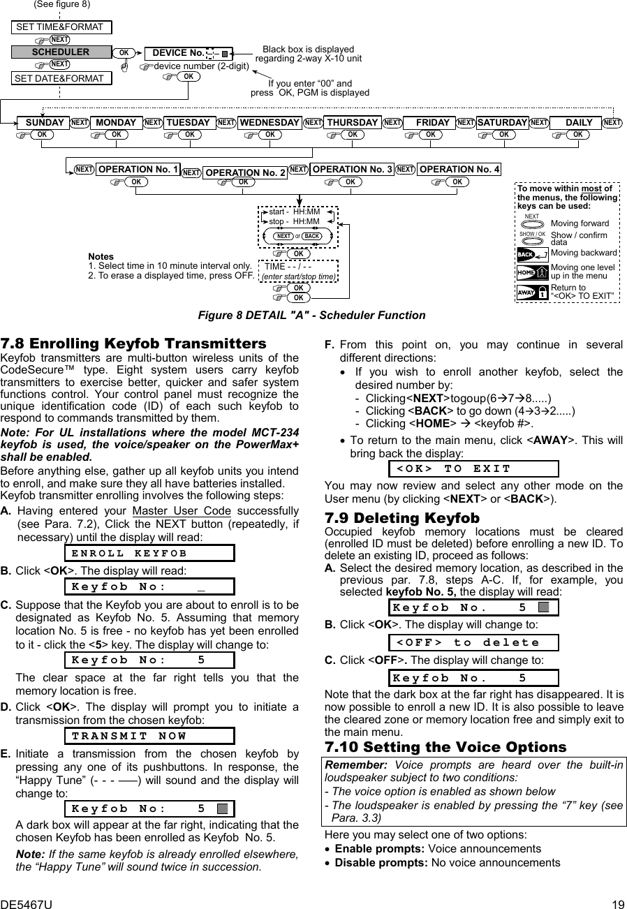
![DE5467U 21 7.15 Setting the Date and Date Format Having entered your Master User Code successfully (see Para. 7.2), click NEXT button (repeatedly, if necessary) until the display will read SET DATE&FORMAT. From here, proceed as follows: Action Resultant Display Sound DATE MM/DD/YYYY If not satisfied DATE DD/MM/YYYY DATE --/--/---- [DATE] (e.g. 01/01/2002) DATE 01/01/2002 DATE 01/01/2002 DATE DD/MM/YYYY ☺ You may now select any other item on the USER SETTINGS menu or quit programming by clicking <AWAY>. When <OK> TO EXIT is displayed - click <OK. 7.16 Scheduler Function The Scheduler enables to start and stop activity of the desired devices. You can select the day (Sunday, Monday, Tuesday, Wednesday, Thursday, Friday, Saturday, or daily) and then select the scheduled activity start/stop of the desired device. The process is demonstrated in "figure 8 DETAIL A". 7.17 Installer Mode If the feature USER PERMIT was enabled by the system installer, the installer will be able to access the INSTALLER MODE only by using this menu, meaning that the INSTALLER MODE (described in the installer guide) can be accessed only with user permission (by using the user code). 8. READING THE EVENT LOG 8.1 Event Log Description All events are memorized in an event log that contains up to 100 entries. You can access this log, review the events one by one and draw functional conclusions. If the event log fills up completely (the number of registered events reaches 100) it continues to accept new events at the expense of old events - the oldest event is deleted upon registration of each new event. The date and time of occurrence are memorized for each event. When reading the event log, events are shown in chronological order - from the newest to the oldest. Because of the limited display space, the event description is shown first, then the date and time. The two displays are shown alternately several times, until you click <OK> to move on to an older event, or until the “no action” 4-minute timeout restores the system to the normal operating mode. Access to the event log is provided by clicking the asterisk () key and then keying your master user code. Should you wish to get an overall view of using the log, refer to Figure 9. The flow chart may even serve as your only guide to using the event log, instead of going through the written step-by-step procedure. Attention: The systemwill not allow you toerase the event log.Only the installer isauthorized to view andperform this functionOKOldest EventEvent Before LastLatest EventLIST OF EVENTSOKOKENTER CODE _ _ _ _(Enter 4-digitmaster user code)<OK TO EXITCLEAR EVENT LOG NEXTNEXTNEXT(Return to normaloperation)OK Figure 9. Using the Event Log 8.2 Reading Procedure To read the event log, proceed as follows: A. While the system is in the normal operating mode, click the asterisk () key. The display will change to: ENTER CODE_ _ _ _ B. Enter the current master user code. If the code is correct, the “Happy Tune“ will sound and the display will read: LIST OF EVENTS Important! Entering an incorrect code 5 times in a row will initiate a 30-second penalty lockout of the keypad. C. Click <OK>. The latest event will be shown. Suppose that the latest event was an alarm in zone 13. The display will now read: Z13 ALARM and then: 09/02/99 3:37P The two displays will be shown alternately until you click <OK> again to move to the next event, or until the event log times out (4 minutes). D. Click <OK> as many times as necessary to read all the data you need. To quit the event log: - Click <HOME> or <AWAY> from any- where within the log. The display will read: <OK> TO EXIT - Click <OK>. The system will return to the normal operating mode.](https://usermanual.wiki/Visonic/PWRMAXPLUS.Users-Manual/User-Guide-408682-Page-21.png)