Visonic PWRMAXPLUS Alarm System Control Panel User Manual Installation Instructions
Visonic Inc. Alarm System Control Panel Installation Instructions
Visonic >
Contents
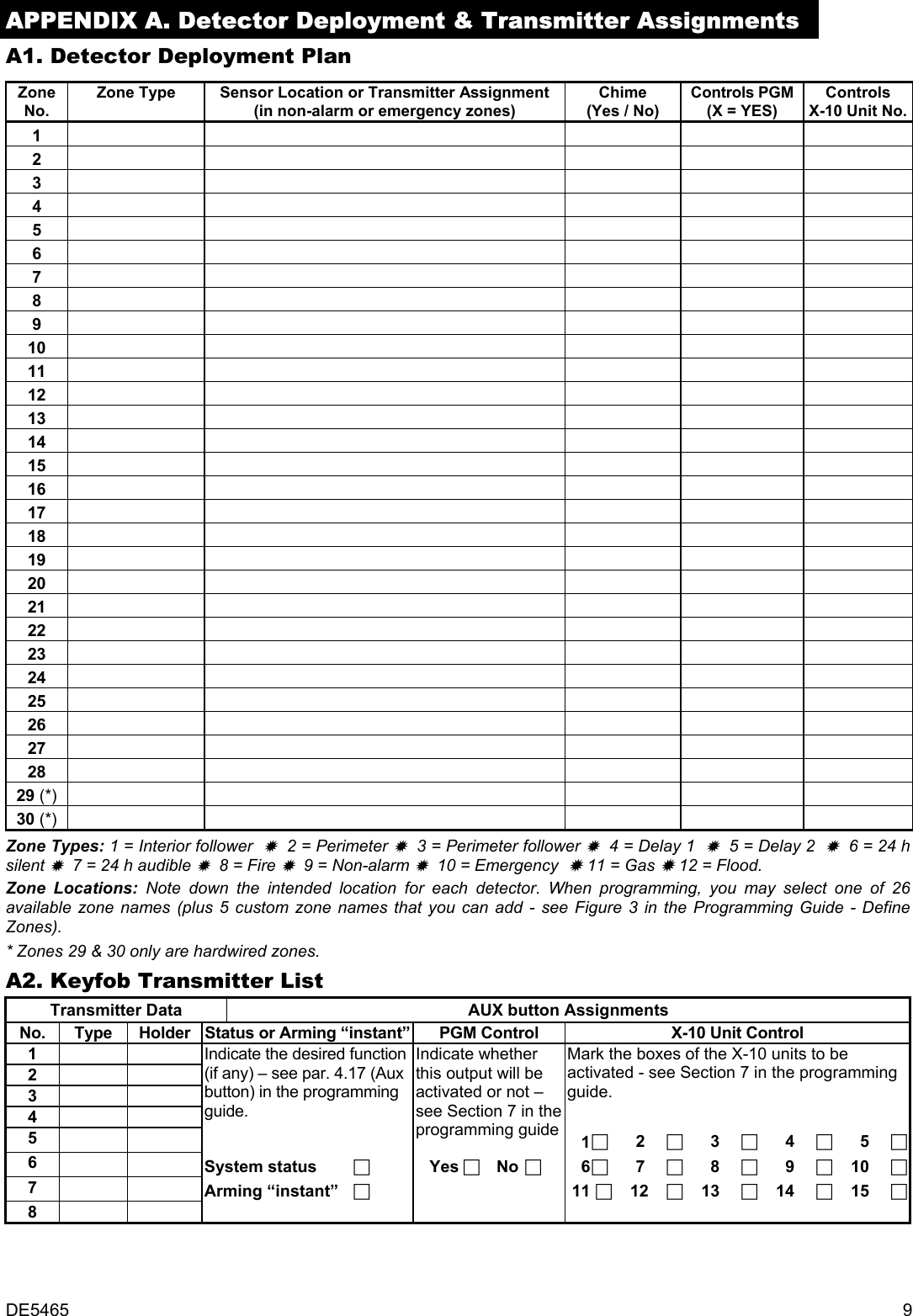
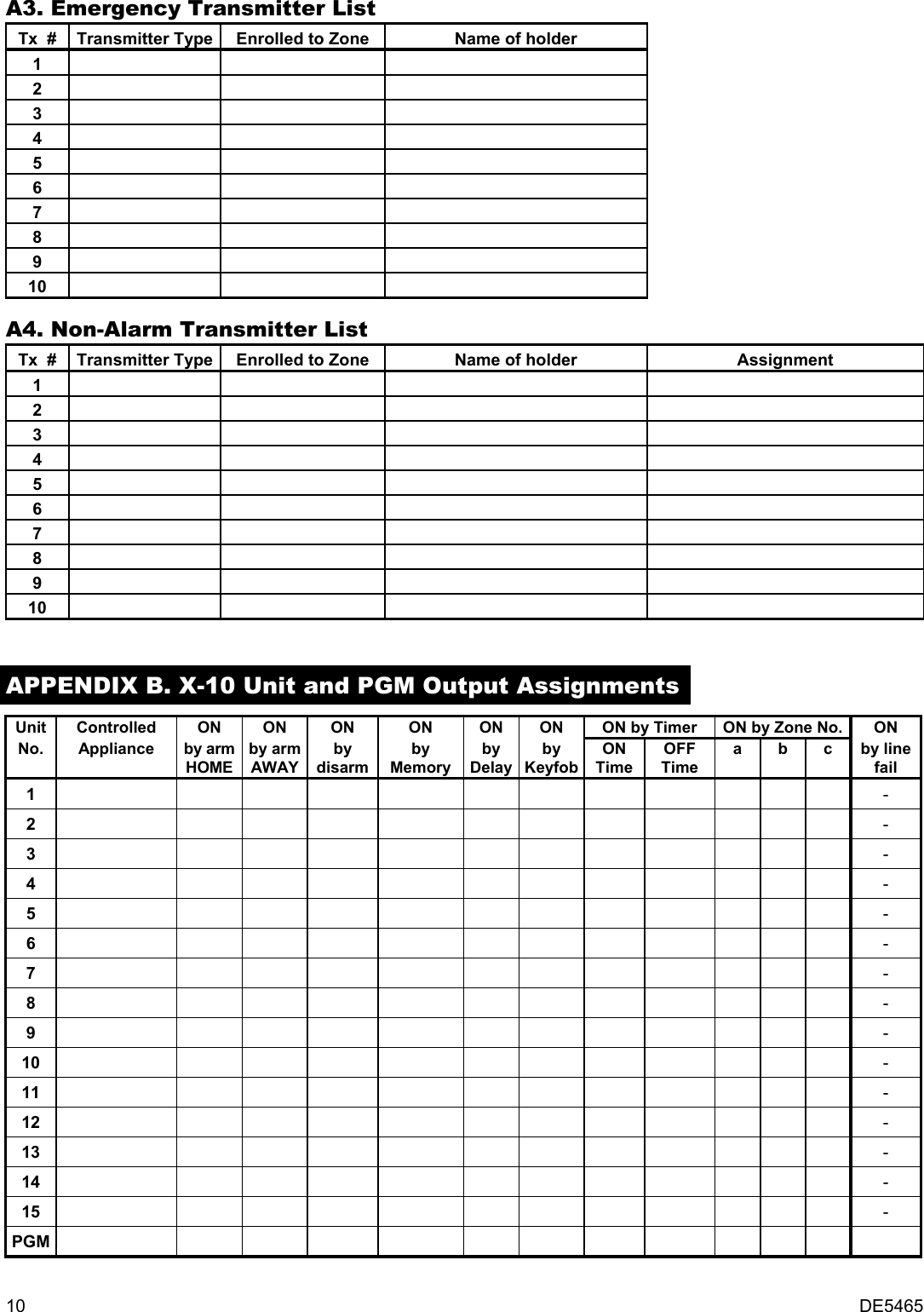
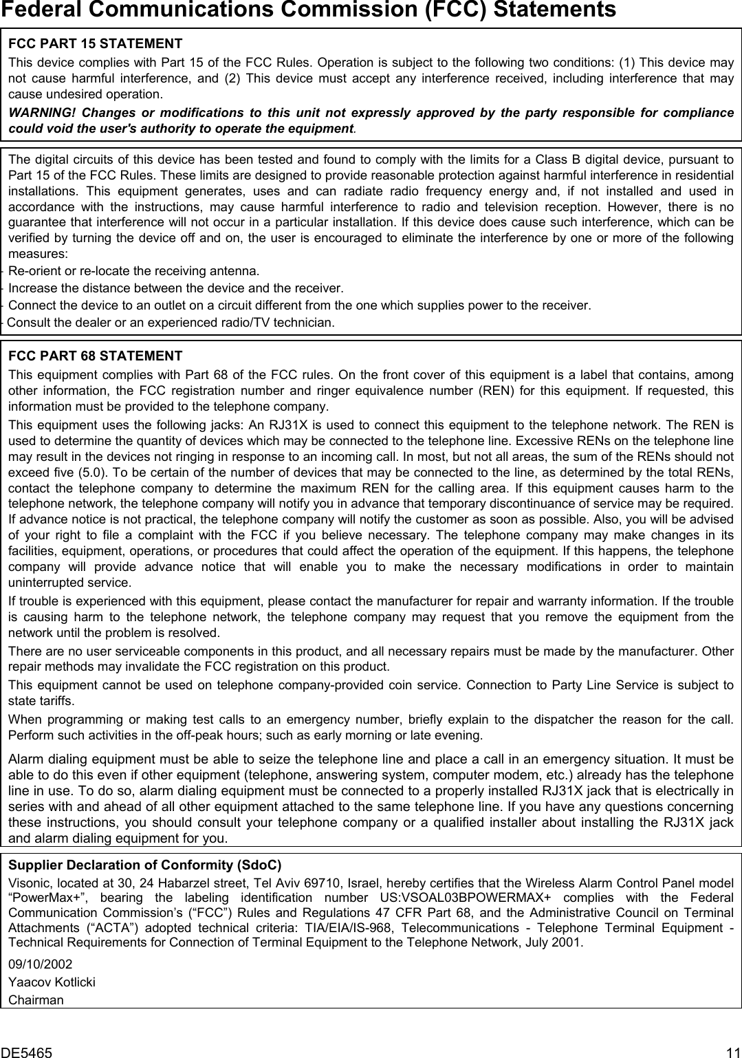
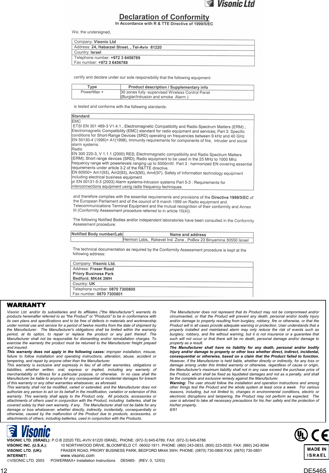
- 1. Installation Instructions
- 2. Users Manual
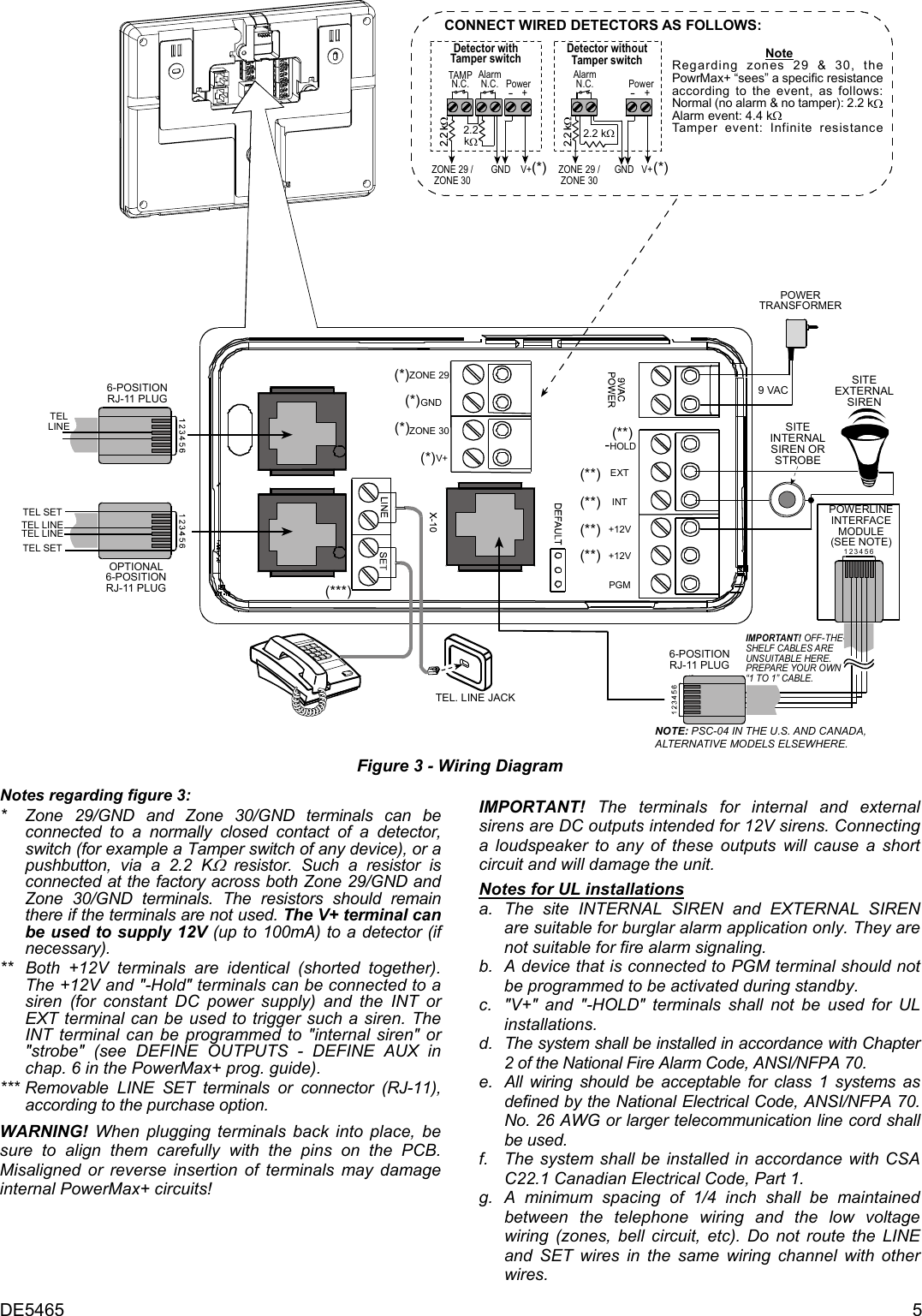
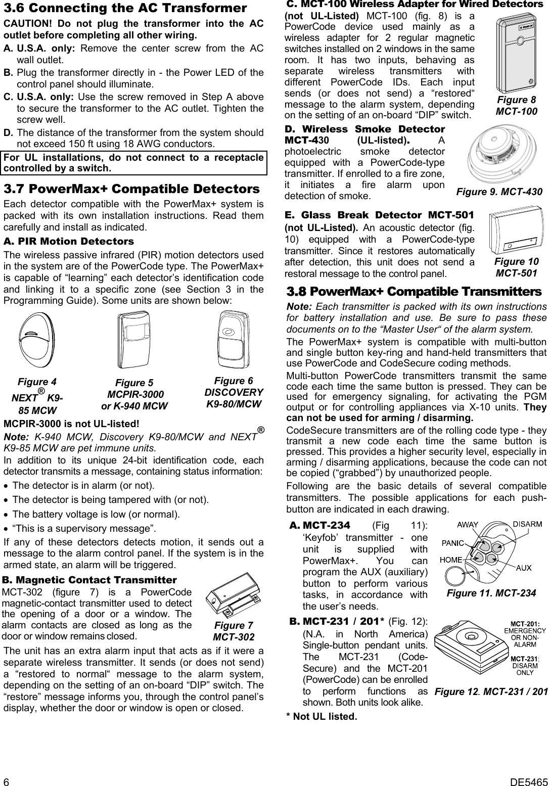
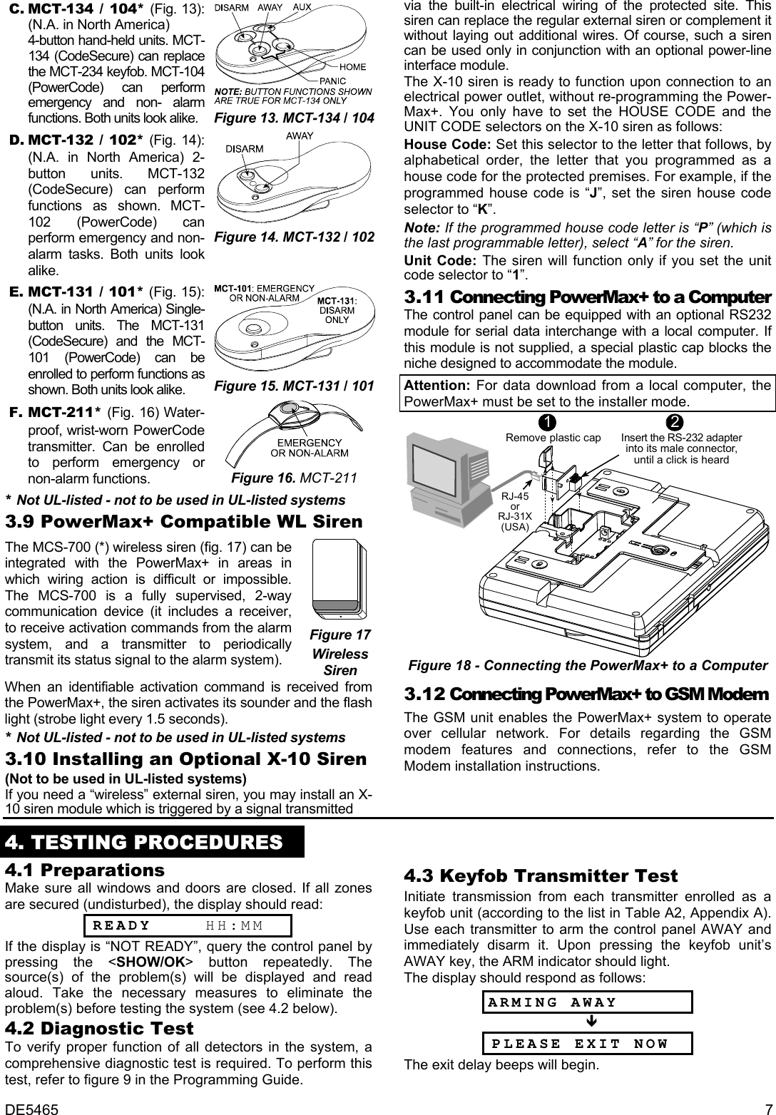
Installation Instructions