Visonic RFD PG2 RF Module, RFD User Manual
Visonic Ltd. PG2 RF Module, RFD
UserManual.wiki
>
Visonic
>
RFD User Manual
User Manual
Navigation menu
Upload a User Manual
Namespaces
Wiki Guide
HTML
PDF
Info
Views
User Manual
Discussion / Help
Navigation

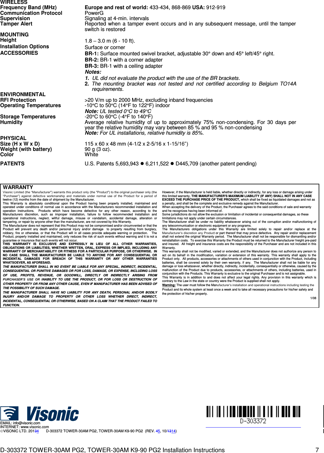
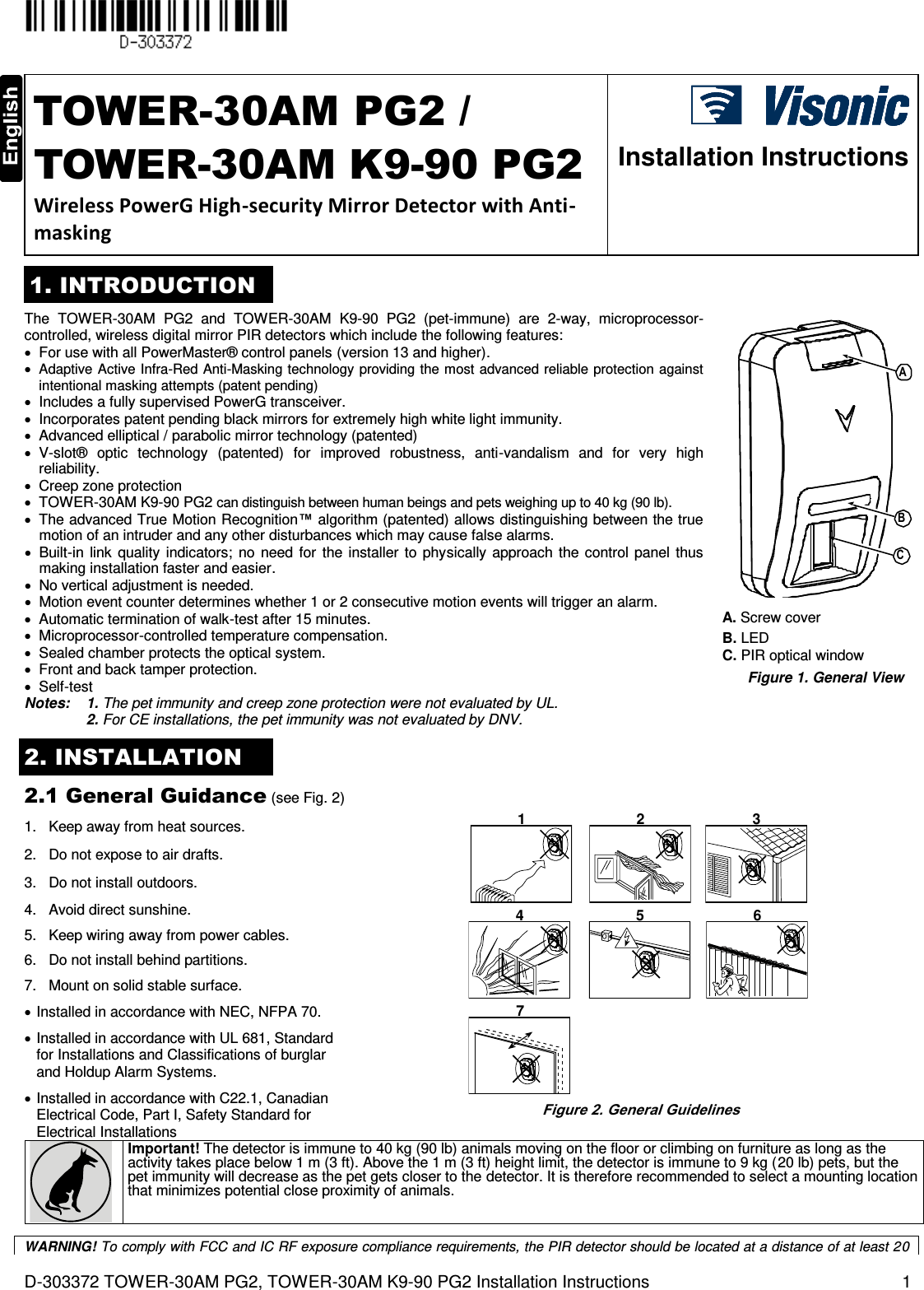
![2 D-302413 NEXT PG2, NEXT K9-85 PG2 Installation Instructions 2.2 Mounting (see Fig. 3) Notes: 1. Mount the detector so that its orientation is perpendicular to the expected intrusion path. 2. For installations of detector at 2m high, Dead zone is 2ft at 0m high and 0.5ft at 1.5m high. 123BA 4C D 1. Release screw and remove cover. 2. Push catch and remove board. 3. Insert battery. 4. Mounting A. Front Tamper switch B. Back Tamper switch. C. On surface D. In corner Caution! Risk of explosion if battery is replaced by an incorrect type. Dispose of used battery according to manufacturer's instructions. Note: Back Tamper must be enabled for UL installations.Figure 3. Mounting 2.3. Enrollment Refer to the PowerMaster panel's Installer Guide and follow the procedure under the "02:ZONES/DEVICES" option of the Installer Menu. A general description of the procedure is provided in the following flow chart. Step 1 Step 2 Step 3 Step 4 Step 5 Step 6 Enter the Installer menu and select “02:ZONES/DEVICES” Select "ADD NEW DEVICE" Option See Note [1] Enroll the device or Enter the device ID Select the desired Zone Number Configure Location, Zone Type & Chime Parameters Configure the Detector means scroll and select See Note [2] Notes: [1] If the detector is already enrolled you can configure the detector parameters via the “Modify Devices” option – see Step 2. [2] Select the "Device Settings" option and refer to section 2.4 to configure the detector parameters. 2.4. Configuring the Detector Parameters Enter the menu and follow the configuration instructions for the Next PG2 / Next K9-85 PG2 PIR detector as described in the following table. Option Configuration Instructions Here you determine whether or not the alarm LED indication will be activated. Optional settings: LED ON (default) and LED OFF. Here you determine whether an alarm will be activated upon continued motion (low sensitivity) or upon a single alarm event (high sensitivity).. Optional settings: LOW sensitive (default) and HIGH sensitive. Here you determine whether or not to set the activity time during disarm. Optional settings: NOT Active (default), YES – no delay, YES + 5s delay, YES + 15s delay, YES + 30s delay, YES + 1m delay, YES + 2m delay, YES + 5m delay, YES + 10m delay, YES + 20m delay and YES + 60m delay. DISARM Activity Event Counter Alarm LED DEVICE SETTINGS Z14.DEV SETTINGS Z14.SET CHIME Z14.ZONE TYPE Z14.LOCATION ID No. 120-XXXX Z14:Motion Sens ENTR ID:XXX-XXXX ENROLL NOW or MODIFY DEVICES ADD NEW DEVICES 02.ZONES/DEVICES](https://usermanual.wiki/Visonic/RFD/User-Guide-2481094-Page-2.png)

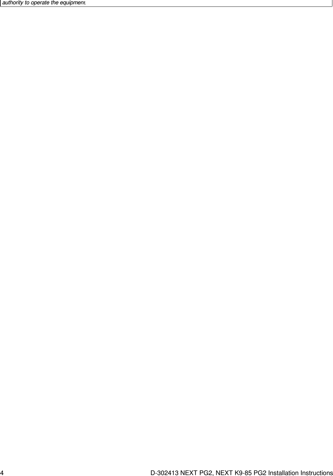
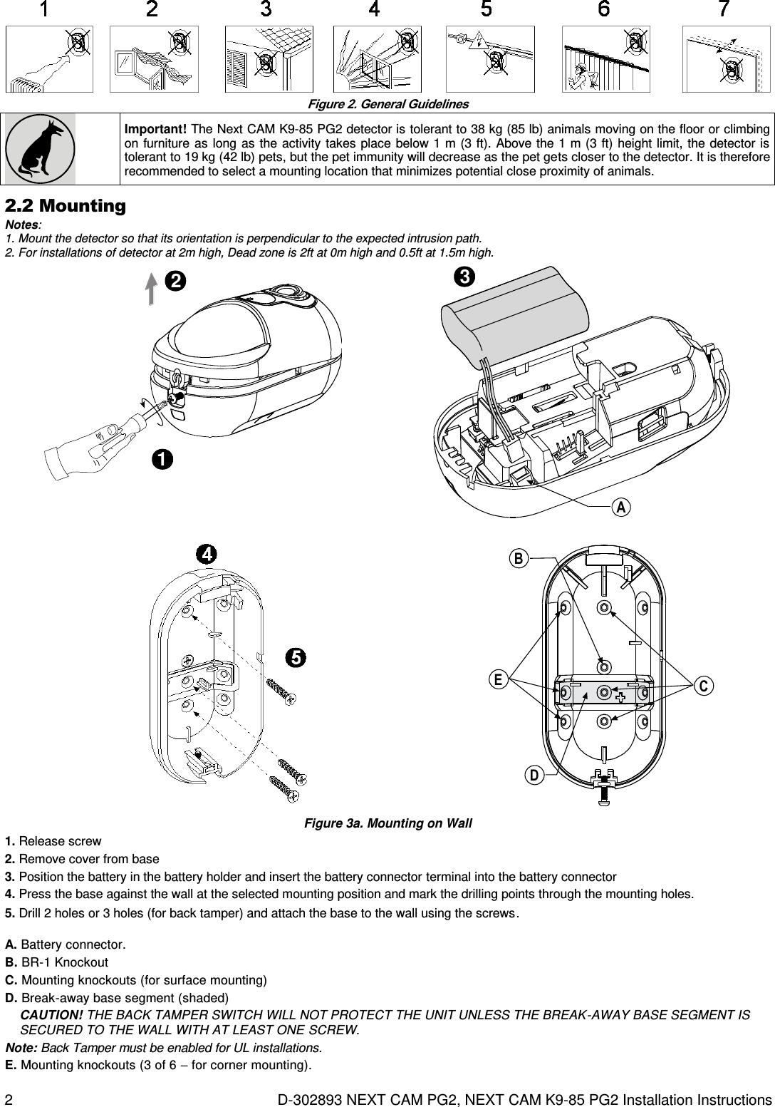
![D-302893 NEXT CAM PG2, NEXT CAM K9-85 PG2 Installation Instructions 1 NEXT CAM PG2, NEXT CAM K9-85 PG2 PowerG, Wireless, [Pet-tolerant] PIR Motion detector with Integrated Camera Installation Instructions 1. INTRODUCTION The Next CAM PG2 / Next CAM K9-85 PG2 is a 2-way, microprocessor-controlled, wireless digital PIR detector with integrated camera and microphone for alarm verification. Activated upon PIR detection or upon demand, the Next CAM PG2 / Next CAM K9-85 PG2 sends clear images with optional audio to the Monitoring Station. It thus enables accurate status assessment of the premises. The PIR detector's features are as follows: For use with all PowerMaster® control panels (version 15 and higher). Up to 12 meters (40 ft). 90 angle camera overlaps PIR field of view 10 meter (33 ft) range in complete darkness overlaps PIR range Wall creep zone protection. For pet tolerant version - Target Specific Imaging™ (TSI) technology is used for distinction between human beings and pets weighing up to 38 kg (85lb). Includes a fully supervised PowerG transceiver. BACDE A. Microphone B. Camera lens C. IR LED D. Light sensor E. LEDs Fig. 1. External View True Motion Recognition™ algorithm. In Next CAM PG2, built-in link quality indicators; no need for the installer to physically approach the control panel thus making installation faster and easier. No vertical adjustment is needed. Temperature compensation. Sealed chamber protects the optical system from insects. Front cover and back tamper, for improved tamper protection. White light protection. The camera's features are as follows: Up to 10 cameras Optional audio with images for listen -in Images multiplexed from all cameras Color and back & white images Auto-setup (brightness, contrast) Camera tuning by simple walk-test Day and night CMOS camera, with IR illumination. This allows taking pictures in full darkness without letting the intruder know. Instant capture: guarantees capture of fast moving intruder. Camera operation modes: o Post alarm – pictures are taken after detection by detector. o On demand – pictures are taken after a command from the monitoring station. An event records 2 images per second. 10-15 images total (can be customized by request) Works with repeaters for extended range Notes: 1. The camera and the listen-in feature are not to be enabled in UL listed product. 2. The pet immunity feature was not evaluated by UL. 3. The microphone is not to be enabled in a UL listed product. 4. For CE installations, the pet immunity was not evaluated by DNV. 2. INSTALLATION 2.1 General Guidance (see Fig. 2) 1. Keep away from heat sources. 2. Do not expose to air drafts. 3. Do not install outdoors. 4. Avoid direct sunshine. 5. Keep wiring away from power cables. 6. Do not install behind partitions. 7. Mount on solid stable surface. 8. Installed in accordance with NEC, NFPA 70. 9. Installed in accordance with UL 681, Standard for Installations and Classifications of burglar and Holdup Alarm Systems. 10. Installed in accordance with C22.1, Canadian Electrical Code, Part I, Safety Standard for Electrical Installations. WARNING! To comply with FCC and IC RF exposure compliance requirements, the PIR detector should be located at a distance of at least 20 cm from all persons during normal operation. The antennas used for this product must not be co-located or operated in conjunction with any other antenna or transmitter](https://usermanual.wiki/Visonic/RFD/User-Guide-2481094-Page-6.png)
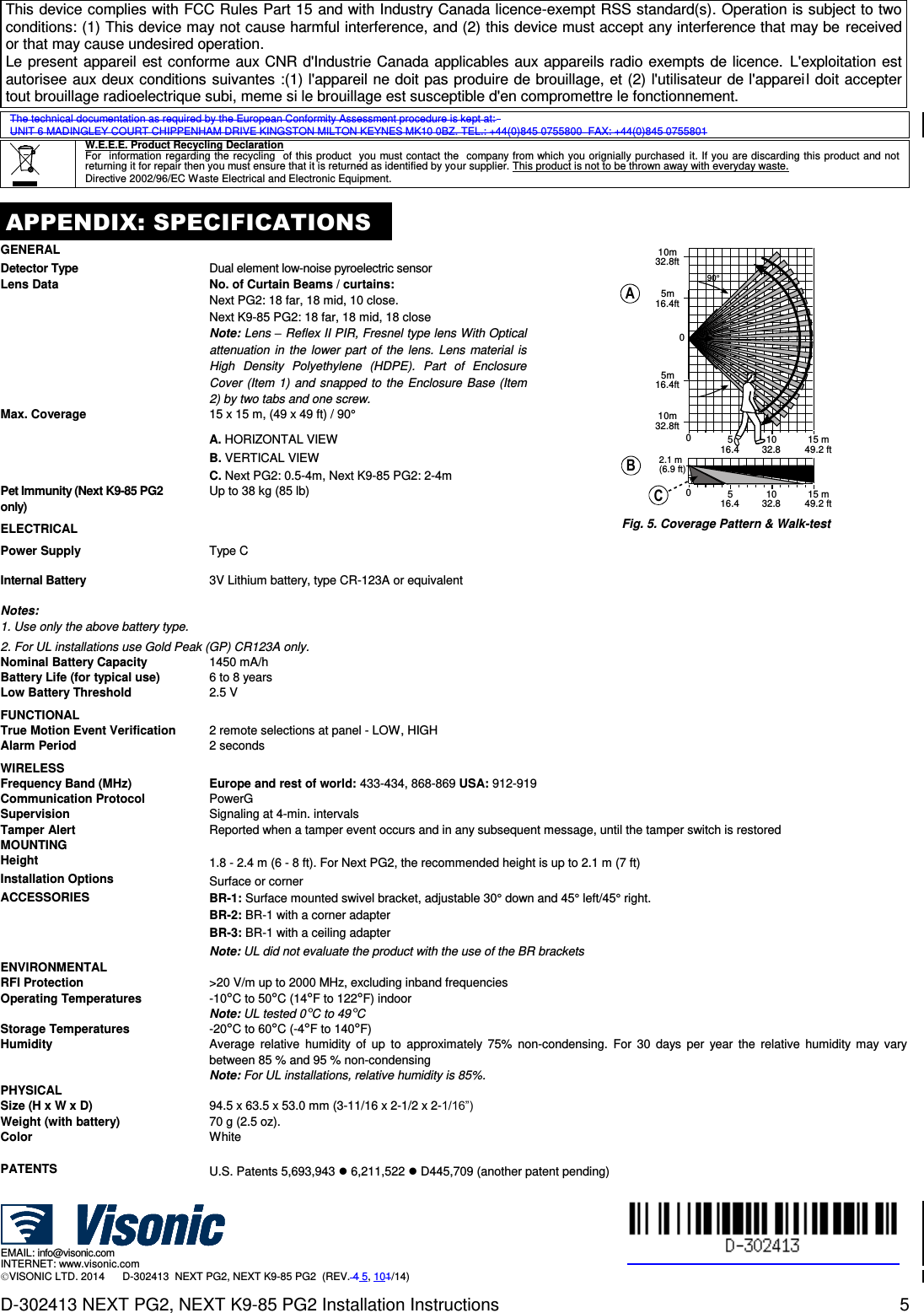
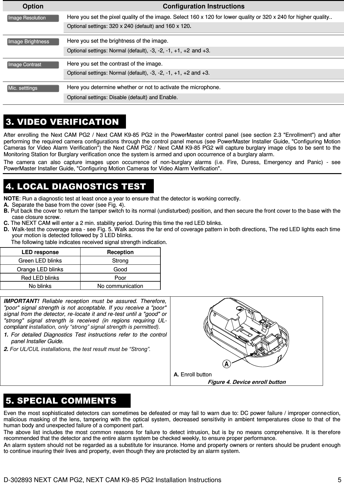
![D-302893 NEXT CAM PG2, NEXT CAM K9-85 PG2 Installation Instructions 3 Caution! Risk of explosion if battery is replaced by an incorrect type. Dispose of used battery according to manufacturer's instructions. 76 Figure 3b. Final Closure 6. Align the cover with the base. 7. Secure with screw. 2.3. Enrollment Refer to the PowerMaster panel's Installer Guide and follow the procedure under the "02:ZONES/DEVICES" option of the Installer Menu. A general description of the procedure is provided in the following flow chart. Step 1 Step 2 Step 3 Step 4 Step 5 Step 6 Enter the Installer menu and select “02:ZONES/DEVICES” Select "ADD NEW DEVICE" Option See Note [1] Enroll the device or Enter the device ID Select the desired Zone Number Configure Location, Zone Type & Chime Parameters Configure the Detector means scroll and select See Note [2] Notes: [1] If the detector is already enrolled you can configure the detector parameters via the “Modify Devices” option – see Step 2. [2] Select the "Device Settings" option and refer to section 2.4 to configure the detector parameters. 2.4. Configuring the Detector Parameters Enter the menu and follow the configuration instructions for the Next CAM PG2 / Next CAM K9-85 PG2 PIR detector as described in the following table. Option Configuration Instructions Here you determine whether or not the alarm LED indication will be activated. Optional settings: LED ON (default) and LED OFF. Here you determine whether an alarm will be activated upon continued motion (low sensitivity) or upon a single alarm event (high sensitivity).. Optional settings: LOW sensitive (default) and HIGH sensitive. Here you determine whether or not to set the activity time during disarm. Optional settings: NOT Active (default), YES – no delay, YES + 5s delay, YES + 15s delay, YES + 30s delay, YES + 1m delay, YES + 2m delay, YES + 5m delay, YES + 10m delay, YES + 20m delay and YES + 60m delay. Note: Not applicable in this version. Do not change this setting! Here you determine whether or not to report power failure and restore. Optional settings: NOT connected (default) and Connected to AC. Here you determine whether the image will be in black & white or color. Optional settings: Black & White (default) and Color. Image Color AC POWER Connect DISARM Activity Event Counter Alarm LED DEVICE SETTINGS Z10.DEV SETTINGS Z10.SET CHIME Z10.ZONE TYPE Z10.LOCATION ID No. 140-XXXX Z10:Motion Camra ENTR ID:XXX-XXXX ENROLL NOW or MODIFY DEVICES ADD NEW DEVICES 02.ZONES/DEVICES](https://usermanual.wiki/Visonic/RFD/User-Guide-2481094-Page-8.png)
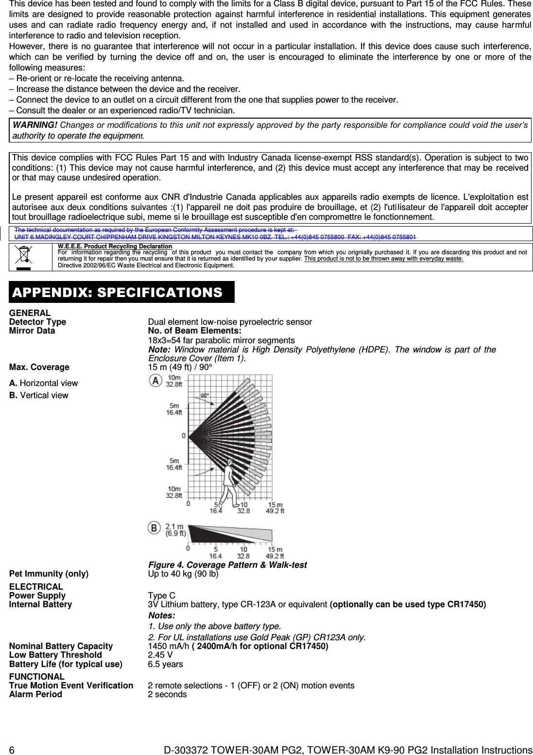
![4 D-303372 TOWER-30AM PG2, TOWER-30AM K9-90 PG2 Installation Instructions 5 6 DEF 5. Insert battery while observing polarity. D. Enroll button (use a screwdriver to press the recessed button) E. Battery F. Tamper switch CAUTION! THE BACK TAMPER SWITCH WILL NOT PROTECT THE UNIT UNLESS THE BREAK-AWAY BASE SEGMENT IS SECURED TO THE WALL WITH AT LEAST ONE SCREW. CAUTION! RISK OF EXPLOSION IF BATTERY IS REPLACED BY AN INCORRECT TYPE. DISPOSE OF USED BATTERY ACCORDING TO MANUFACTURER'S INSTRUCTIONS. Note: Back Tamper must be enabled for UL installations. Figure 3. Mounting 2.3. Enrollment Refer to the PowerMaster control panel's Installer Guide and follow the procedure under the "02:ZONES/DEVICES" option of the Installer Menu. A general description of the procedure is provided in the following flow chart. Step 1 Step 2 Step 3 Step 4 Step 5 Step 6 Enter the Installer menu and select “02:ZONES/DEVICES” Select "ADD NEW DEVICE" Option See Note [1] Enroll the device or Enter the device ID Select the desired Zone Number Configure Location, Zone Type & Chime Parameters Configure the Detector means scroll and select See Note [2] Notes: [1] If the detector is already enrolled you can configure the detector parameters via the “Modify Devices” option – see Step 2. [2] Select the "Device Settings" option and refer to section 2.4 to configure the detector parameters. 2.4. Configuring the Detector Parameters Enter the menu and follow the configuration instructions for the TOWER-30AM PG2 PIR detector as described in the following table. Option Configuration Instructions Define whether or not the alarm LED indication will be activated. Optional settings: LED ON (default) and LED OFF. Define whether an alarm will be activated upon continued motion (low sensitivity) or upon a single alarm event (high sensitivity). Optional settings: LOW sensitive (default) and HIGH sensitive. Define whether or not to set the activity time during disarm. Optional settings: NOT Active (default), YES – no delay, YES + 5s delay, YES + 15s delay, YES + 30s delay, YES + 1m delay, YES + 2m delay, YES + 5m delay, YES + 10m delay, YES + 20m delay and YES + 60m delay. Define the activity and the sensitivity level of the anti-masking. Optional settings: LOW sensitive (default), HIGH sensitive and disabled. 3. LOCAL DIAGNOSTICS TEST NOTE: Run a diagnostic test at least once a year to ensure that the detector is working correctly. A. Separate the base from the cover (see Fig. 3). ANTI MASKING-AM DISARM Activity Event Counter Alarm LED DEVICE SETTINGS Z14.DEV SETTINGS Z14.SET CHIME Z14.ZONE TYPE Z14.LOCATION ID No. 123-XXXX Z14:Motion Sens ENTR ID:XXX-XXXX ENROLL NOW or MODIFY DEVICES ADD NEW DEVICES 02.ZONES/DEVICES](https://usermanual.wiki/Visonic/RFD/User-Guide-2481094-Page-17.png)
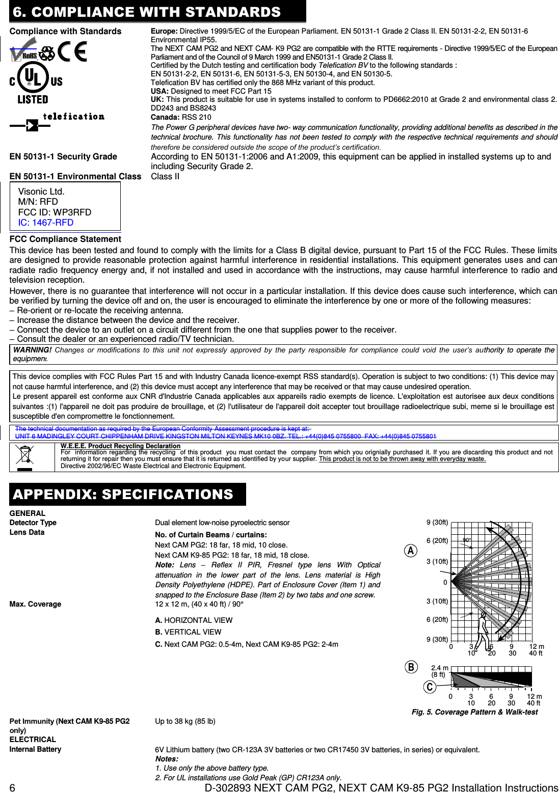
![D-303372 TOWER-30AM PG2, TOWER-30AM K9-90 PG2 Installation Instructions 5 B. Put back the cover to return the tamper switch to its normal (undisturbed) position, and then secure the front cover to the base with the case closure screw. C. The TOWER-30AM PG2 will enter a 2 min. stability period. During this time the red LED blinks. D. Walk-test the coverage area - see Figure 4. Walk across the far end of coverage pattern in both directions; the red LED lights each time your motion is detected followed by 3 LED blinks. The following table indicates the received signal strength indication. LED response Reception Green LED blinks Strong Orange LED blinks Good Red LED blinks Poor No blinks No communication IMPORTANT! Reliable reception must be assured. Therefore, "poor" signal strength is not acceptable. If you receive a "poor" signal from the detector, re-locate it and re-test until a "good" or "strong" signal strength is received (in regions requiring UL-compliant installation, only “strong” signal strength is permitted). 1. For detailed Diagnostics Test instructions refer to the control panel Installer Guide. 2. For UL/CUL installations, the test result must be “Strong”. 4. EVENT INDICATIONS LED Indications Event Red LED blinks Stabilization (warm-up 120 sec) Red LED ON 0.2 sec. Tamper open / close Red on 2 sec. Intruder alarm Yellow LED on AM detection – diagnostic mode Yellow LED blinks slowly (0.2 sec. ON, 30 sec. OFF) AM detection – Normal mode Yellow and red LED blink simultaneously (0.2 sec. ON [both], 0.2 sec. OFF) Self-test failure – Diagnostic mode Yellow and red LED blink simultaneously slowly (0.2 sec. ON [both], 30 sec. OFF) Self-test failure – Normal mode 5. SPECIAL COMMENTS Even the most sophisticated detectors can sometimes be defeated or may fail to warn due to: DC power failure / improper connection, malicious masking of the lens, tampering with the optical system, decreased sensitivity in ambient temperatures close to that of the human body and unexpected failure of a component part. The above list includes the most common reasons for failure to detect intrusion, but is by no means comprehensive. It is therefore recommended that the detector and the entire alarm system be checked weekly, to ensure proper performance. An alarm system should not be regarded as a substitute for insurance. Home and property owners or renters should be prudent enough to continue insuring their lives and property, even though they are protected by an alarm system. 6. COMPLIANCE WITH STANDARDS Europe (CE): EN 50131-1, EN 300220, EN 301489, EN 60950, EN 50130-4, EN 50130-5, EN 50131-2-2 Grade 3 Class II, EN 50131-6 The TOWER-30 AM PG2 and TOWER-30 AM K9-90 PG2 are compatible with the RTTE requirements - Directive 1999/5/EC of the European Parliament and of the Council of 9 March 1999. Certified by the Dutch testing and certification body Telefication BV to the following standards : EN 50131-2-2, EN 50131-6, EN 50131-5-3, EN 50130-4, and EN 50130-5. Telefication BV has certified only the 868 MHz variant of this product. UK: This product is suitable for use in systems installed to conform to PD6662:2010 in accordance with EN 50131-2-2 security Grade 3 and environmental Class 2. DD243 and BS8243 USA: CFR 47 Part 15 (FCC) Canada: RSS 210 The Power G peripheral devices have two- way communication functionality, providing additional benefits as described in the technical brochure. This functionality has not been tested to comply with the respective technical requirements and should therefore be considered outside the scope of the product’s certification. EN 50131-1 Security Grade According to EN 50131-1:2006 and A1:2009, this equipment can be applied in installed systems up to and including Security Grade 2. EN 50131-1 Environmental Class Class II FCC Compliance Statement Visonic Ltd. M/N: RFD FCC ID: WP3RFD IC: 1467-RFD](https://usermanual.wiki/Visonic/RFD/User-Guide-2481094-Page-18.png)