User Manual
D-302413 NEXT PG2, NEXT K9-85 PG2 Installation Instructions 1
NEXT PG2 /
NEXT K9-85 PG2
PowerG, Wireless, PIR /Pet Tolerant Motion Detector
Installation Instructions
1. INTRODUCTION
The Next PG2 and Next K9-85 PG2 are 2-way, microprocessor-controlled, wireless digital PIR detectors.
The detectors features are as follows:
For use with all PowerMaster® control panels (version 10 and higher).
Combined Fresnel and cylindrical optics, up to 15 meters (49 ft).
The Next PG2 includes wall creep zone protection.
In Next PG2 and Next K9-85 PG2, Target Specific Imaging™ (TSI) technology is used for distinction
between human beings and pets weighing up to 38 kg (85lb).
Includes a fully supervised PowerG transceiver.
The advanced True Motion Recognition™ algorithm (patented) allows distinguishing between the true motion
of an intruder and any other disturbances which may cause false alarms.
Sophisticated frequency domain digital signal processing.
Built-in link quality indicators; no need for the installer to physically approach the control panel thus making
installation faster and easier.
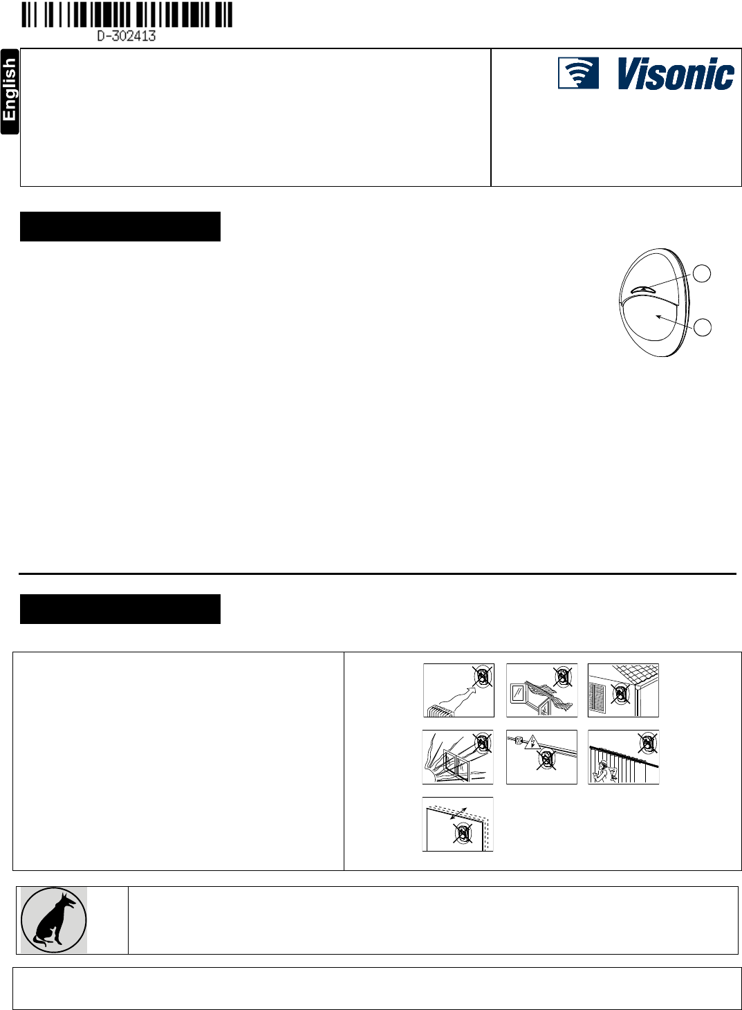
B
A
A. LED
B. Lens
Figure 1: External View
No vertical adjustment is needed.
Motion event counter determines whether 1 or 2 consecutive motion events will trigger an alarm.
Automatic termination of walk-test after 15 minutes.
Microprocessor-controlled temperature compensation.
Sealed chamber protects the optical system.
Front cover and back tamper switches, for improved tamper protection.
White light protection.
Notes: 1. The pet immunity feature was not evaluated by UL.
2. For CE installations, the pet immunity was not evaluated by DNV.
2. INSTALLATION
2.1 General Guidance (see Fig. 2)
1. Keep away from heat sources.
2. Do not expose to air drafts.
3. Do not install outdoors.
4. Avoid direct sunshine.
5. Keep wiring away from power cables.
6. Do not install behind partitions.
7. Mount on solid stable surface.
8. Installed in accordance with NEC, NFPA 70.
9. Installed in accordance with UL 681, Standard for
Installations and Classifications of burglar and Holdup
Alarm Systems.
1 2 3
4 5 6
7
Figure 2. General Guidelines
Important! The Next K9-85 PG2 detector is tolerant to 38 kg (85 lb) animals moving on the floor or climbing on
furniture as long as the activity takes place below 1 m (3 ft). Above the 1 m (3 ft) height limit, the detector is tolerant
to 19 kg (42 lb) pets, but the pet immunity will decrease as the pet gets closer to the detector. It is therefore
recommended to select a mounting location that minimizes potential close proximity of animals.
WARNING! To comply with FCC and IC RF exposure compliance requirements, the PIR detector should be located at a distance of at least 20
cm from all persons during normal operation. The antennas used for this product must not be co-located or operated in conjunction with any
other antenna or transmitter
2 D-302413 NEXT PG2, NEXT K9-85 PG2 Installation Instructions
2.2 Mounting (see Fig. 3)
Notes:
1. Mount the detector so that its orientation is perpendicular to the expected intrusion path.
2. For installations of detector at 2m high, Dead zone is 2ft at 0m high and 0.5ft at 1.5m high.
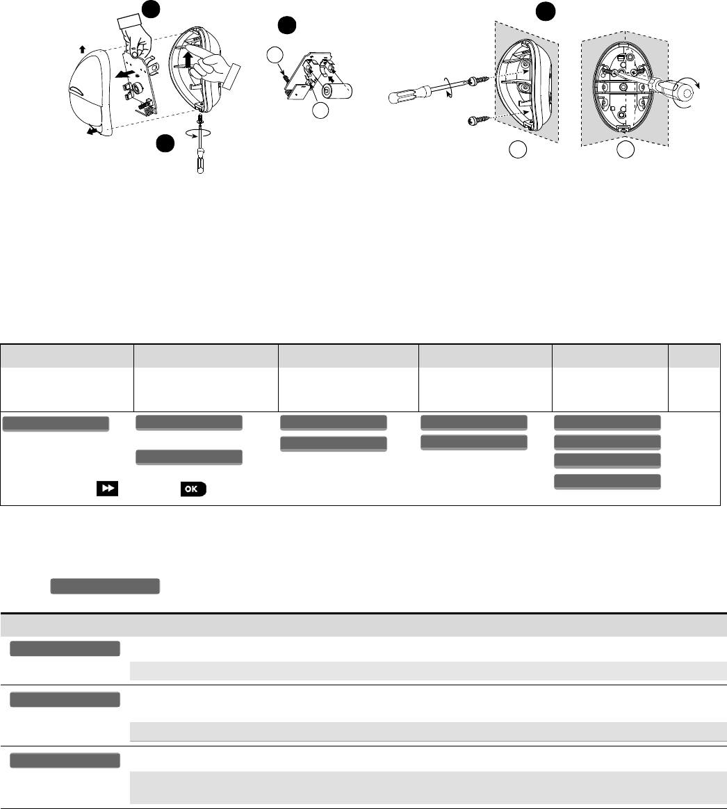
1
2
3
B
A
4
C D
1. Release screw and remove cover.
2. Push catch and remove board.
3. Insert battery.
4. Mounting
A. Front Tamper switch
B. Back Tamper switch.
C. On surface
D. In corner
Caution!
Risk of explosion if battery is replaced by an incorrect type. Dispose of used battery according to manufacturer's instructions.
Note: Back Tamper must be enabled for UL installations.Figure 3. Mounting
2.3. Enrollment
Refer to the PowerMaster panel's Installer Guide and follow the procedure under the "02:ZONES/DEVICES" option of the Installer Menu.
A general description of the procedure is provided in the following flow chart.
Step 1
Step 2
Step 3
Step 4
Step 5
Step 6
Enter the Installer menu
and select
“02:ZONES/DEVICES”
Select "ADD NEW
DEVICE" Option
See Note [1]
Enroll the device or Enter
the device ID
Select the desired Zone
Number
Configure Location,
Zone Type &
Chime Parameters
Configure
the
Detector
means scroll and select
See Note
[2]
Notes:
[1] If the detector is already enrolled you can configure the detector parameters via the “Modify Devices” option – see Step 2.
[2] Select the "Device Settings" option and refer to section 2.4 to configure the detector parameters.
2.4. Configuring the Detector Parameters
Enter the menu and follow the configuration instructions for the Next PG2 / Next K9-85 PG2 PIR detector as described in the
following table.
Option
Configuration Instructions
Here you determine whether or not the alarm LED indication will be activated.
Optional settings: LED ON (default) and LED OFF.
Here you determine whether an alarm will be activated upon continued motion (low sensitivity) or upon a single
alarm event (high sensitivity)..
Optional settings: LOW sensitive (default) and HIGH sensitive.
Here you determine whether or not to set the activity time during disarm.
Optional settings: NOT Active (default), YES – no delay, YES + 5s delay, YES + 15s delay, YES + 30s delay,
YES + 1m delay, YES + 2m delay, YES + 5m delay, YES + 10m delay, YES + 20m delay and YES + 60m delay.
DISARM Activity
Event Counter
Alarm LED
DEVICE SETTINGS
Z14.DEV SETTINGS
Z14.SET CHIME
Z14.ZONE TYPE
Z14.LOCATION
ID No. 120-XXXX
Z14:Motion Sens
ENTR ID:XXX-XXXX
ENROLL NOW or
MODIFY DEVICES
ADD NEW DEVICES
02.ZONES/DEVICES
D-302413 NEXT PG2, NEXT K9-85 PG2 Installation Instructions 3
3. LOCAL DIAGNOSTICS TEST
NOTE: Run a diagnostic test at least once a year to ensure that the detector is working correctly.
A. Separate the base from the cover (see Fig. 3).
B. Put back the cover to return the tamper switch to its normal (undisturbed) position, and then secure the front cover to the base with the
case closure screw.
C. The Next PG2 / Next K9-85 PG2 will enter a 2 min. stability period. During this time the red LED blinks.
D. Walk-test the coverage area - see Fig. 5. Walk across the far end of coverage pattern in both directions, The red LED lights each time
your motion is detected followed by 3 LED blinks.
The following table indicates received signal strength indication.
LED response
Reception
Green LED blinks
Strong
Orange LED blinks
Good
Red LED blinks
Poor
No blinks
No communication
IMPORTANT! Reliable reception must be assured.
Therefore, "poor" signal strength is not acceptable. If you
receive a "poor" signal from the detector, re-locate it and
re-test until a "good" or "strong" signal strength is
received (in regions requiring UL-compliant installation,
only “strong” signal strength is permitted).
Notes:
1. For detailed Diagnostics Test instructions refer to the
control panel Installer Guide.
2. For UL/CUL installations, the test result must be
“Strong”.
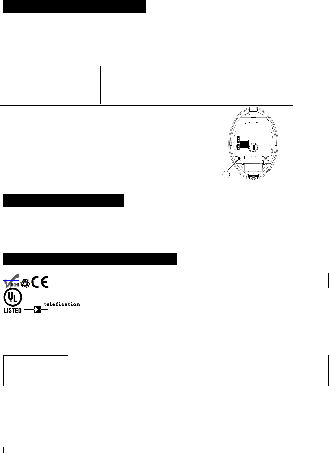
A. ENROLL button
Rx Tx
EVENT
1
2
LED
A
Figure 4. Device enroll button
4. SPECIAL COMMENTS
Even the most sophisticated detectors can sometimes be defeated or may fail to warn due to: DC power failure / improper connection,
malicious masking of the lens, tampering with the optical system, decreased sensitivity in ambient temperatures close to that of the human
body and unexpected failure of a component part.
The above list includes the most common reasons for failure to detect intrusion, but is by no means comprehensive. It is therefore
recommended that the detector and the entire alarm system be checked weekly, to ensure proper performance.
An alarm system should not be regarded as a substitute for insurance. Home and property owners or renters should be prudent enough
to continue insuring their lives and property, even though they are protected by an alarm system.
5. COMPLIANCE WITH STANDARDS
Compliance with Standards
Europe: EN 300220, EN 50131-1 Grade 2, Class II. EN 301489, EN 50130-4, EN 60950, EN 50131-2-2,
EN 50131-6 Environmental IP55.
The NEXT PG2 and NEXT K9-85 PG2 are compatible with the RTTE requirements - Directive 1999/5/EC
of the European Parliament and of the Council of 9 March 1999 and EN50131-1 Grade 2 Class II.
Certified by the Dutch testing and certification body Telefication BV to the following standards :
EN 50131-2-2, EN 50131-6, EN 50131-5-3, EN 50130-4, and EN 50130-5.
Telefication BV has certified only the 868 MHz variant of this product.
Also complies to USA: CFR47 Part 15; Canada: RSS 210;
UK: This product is suitable for use in systems installed to conform to PD6662:2010 at Grade 2 and environmental class 2. DD243 and BS8243.
The Power G peripheral devices have two- way communication functionality, providing additional benefits as described in the technical brochure. This functionality has
not been tested to comply with the respective technical requirements and should therefore be considered outside the scope of the product’s certification.
EN 50131-1 Security Grade
According to EN 50131-1:2006 and A1:2009, this equipment can be applied in installed systems
up to and including Security Grade 2.
EN 50131-1 Environmental Class
Class II
This device has been tested and found to comply with the limits for a Class B digital device, pursuant to Part 15 of the FCC Rules. These
limits are designed to provide reasonable protection against harmful interference in residential installations. This equipment generates uses
and can radiate radio frequency energy and, if not installed and used in accordance with the instructions, may cause harmful interference to
radio and television reception.
However, there is no guarantee that interference will not occur in a particular installation. If this device does cause such interference, which can be
verified by turning the device off and on, the user is encouraged to eliminate the interference by one or more of the following measures:
– Re-orient or re-locate the receiving antenna.
– Increase the distance between the device and the receiver.
– Connect the device to an outlet on a circuit different from the one that supplies power to the receiver.
– Consult the dealer or an experienced radio/TV technician.
WARNING! Changes or modifications to this unit not expressly approved by the party responsible for compliance could void the user’s
Visonic Ltd.
M/N: RFD
FCC ID: WP3RFD
IC: 1467-RFD

4 D-302413 NEXT PG2, NEXT K9-85 PG2 Installation Instructions
authority to operate the equipment.
D-302413 NEXT PG2, NEXT K9-85 PG2 Installation Instructions 5
This device complies with FCC Rules Part 15 and with Industry Canada licence-exempt RSS standard(s). Operation is subject to two
conditions: (1) This device may not cause harmful interference, and (2) this device must accept any interference that may be received
or that may cause undesired operation.
Le present appareil est conforme aux CNR d'Industrie Canada applicables aux appareils radio exempts de licence. L'exploitation est
autorisee aux deux conditions suivantes :(1) l'appareil ne doit pas produire de brouillage, et (2) l'utilisateur de l'appareil doit accepter
tout brouillage radioelectrique subi, meme si le brouillage est susceptible d'en compromettre le fonctionnement.
The technical documentation as required by the European Conformity Assessment procedure is kept at:
UNIT 6 MADINGLEY COURT CHIPPENHAM DRIVE KINGSTON MILTON KEYNES MK10 0BZ. TEL.: +44(0)845 0755800 FAX: +44(0)845 0755801
W.E.E.E. Product Recycling Declaration
For information regarding the recycling of this product you must contact the company from which you orignially purchased it. If you are discarding this product and not
returning it for repair then you must ensure that it is returned as identified by your supplier. This product is not to be thrown away with everyday waste.
Directive 2002/96/EC Waste Electrical and Electronic Equipment.
APPENDIX: SPECIFICATIONS
GENERAL
90°
5
0
16.4
0
15 m
49.2 ft
10
32.8
5m
16.4ft
5m
16.4ft
10m
32.8ft
10m
32.8ft
5 10 15 m
0
2.1 m
(6.9 ft)
16.4 32.8 49.2 ft
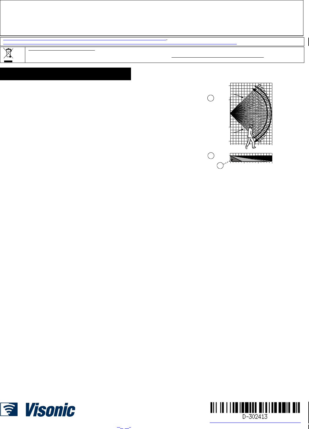
B
A
C
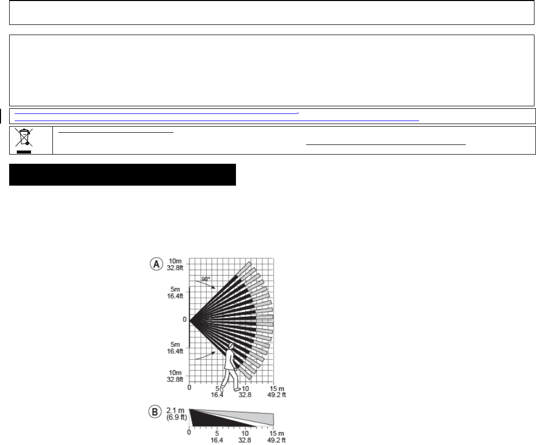
Fig. 5. Coverage Pattern & Walk-test
Detector Type
Dual element low-noise pyroelectric sensor
Lens Data
No. of Curtain Beams / curtains:
Next PG2: 18 far, 18 mid, 10 close.
Next K9-85 PG2: 18 far, 18 mid, 18 close
Note: Lens – Reflex II PIR, Fresnel type lens With Optical
attenuation in the lower part of the lens. Lens material is
High Density Polyethylene (HDPE). Part of Enclosure
Cover (Item 1) and snapped to the Enclosure Base (Item
2) by two tabs and one screw.
Max. Coverage
15 x 15 m, (49 x 49 ft) / 90°
A. HORIZONTAL VIEW
B. VERTICAL VIEW
C. Next PG2: 0.5-4m, Next K9-85 PG2: 2-4m
Pet Immunity (Next K9-85 PG2
only)
Up to 38 kg (85 lb)
ELECTRICAL
Power Supply
Type C
Internal Battery
3V Lithium battery, type CR-123A or equivalent
Notes:
1. Use only the above battery type.
2. For UL installations use Gold Peak (GP) CR123A only.
Nominal Battery Capacity
1450 mA/h
Battery Life (for typical use)
6 to 8 years
Low Battery Threshold
2.5 V
FUNCTIONAL
True Motion Event Verification
2 remote selections at panel - LOW, HIGH
Alarm Period
2 seconds
WIRELESS
Frequency Band (MHz)
Europe and rest of world: 433-434, 868-869 USA: 912-919
Communication Protocol
PowerG
Supervision
Signaling at 4-min. intervals
Tamper Alert
Reported when a tamper event occurs and in any subsequent message, until the tamper switch is restored
MOUNTING
Height
1.8 - 2.4 m (6 - 8 ft). For Next PG2, the recommended height is up to 2.1 m (7 ft)
Installation Options
Surface or corner
ACCESSORIES
BR-1: Surface mounted swivel bracket, adjustable 30° down and 45° left/45° right.
BR-2: BR-1 with a corner adapter
BR-3: BR-1 with a ceiling adapter
Note: UL did not evaluate the product with the use of the BR brackets
ENVIRONMENTAL
RFI Protection
>20 V/m up to 2000 MHz, excluding inband frequencies
Operating Temperatures
-10°C to 50°C (14°F to 122°F) indoor
Note: UL tested 0°C to 49°C
Storage Temperatures
-20°C to 60°C (-4°F to 140°F)
Humidity
Average relative humidity of up to approximately 75% non-condensing. For 30 days per year the relative humidity may vary
between 85 % and 95 % non-condensing
Note: For UL installations, relative humidity is 85%.
PHYSICAL
Size (H x W x D)
94.5 x 63.5 x 53.0 mm (3-11/16 x 2-1/2 x 2-1/16”)
Weight (with battery)
70 g (2.5 oz).
Color
White
PATENTS
U.S. Patents 5,693,943 6,211,522 D445,709 (another patent pending)
EMAIL: info@visonic.com
INTERNET: www.visonic.com
VISONIC LTD. 2014 D-302413 NEXT PG2, NEXT K9-85 PG2 (REV. 4 5, 101/14)
D-302893 NEXT CAM PG2, NEXT CAM K9-85 PG2 Installation Instructions 1
NEXT CAM PG2,
NEXT CAM K9-85 PG2
PowerG, Wireless, [Pet-tolerant] PIR Motion detector
with Integrated Camera
Installation Instructions
1. INTRODUCTION
The Next CAM PG2 / Next CAM K9-85 PG2 is a 2-way,
microprocessor-controlled, wireless digital PIR detector with
integrated camera and microphone for alarm verification. Activated
upon PIR detection or upon demand, the Next CAM PG2 / Next CAM
K9-85 PG2 sends clear images with optional audio to the Monitoring
Station. It thus enables accurate status assessment of the premises.
The PIR detector's features are as follows:
For use with all PowerMaster® control panels (version 15 and
higher).
Up to 12 meters (40 ft).
90 angle camera overlaps PIR field of view
10 meter (33 ft) range in complete darkness overlaps PIR range
Wall creep zone protection.
For pet tolerant version - Target Specific Imaging™ (TSI) technology
is used for distinction between human beings and pets weighing up to
38 kg (85lb).
Includes a fully supervised PowerG transceiver.
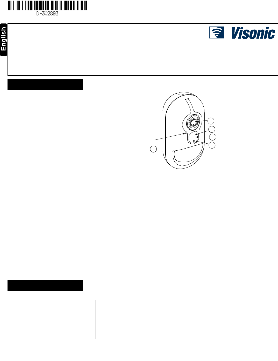
B
A
C
D
E
A. Microphone
B. Camera lens
C. IR LED
D. Light sensor
E. LEDs
Fig. 1. External View
True Motion Recognition™ algorithm.
In Next CAM PG2, built-in link quality indicators; no need for the
installer to physically approach the control panel thus making
installation faster and easier.
No vertical adjustment is needed.
Temperature compensation.
Sealed chamber protects the optical system from insects.
Front cover and back tamper, for improved tamper protection.
White light protection.
The camera's features are as follows:
Up to 10 cameras
Optional audio with images for listen -in
Images multiplexed from all cameras
Color and back & white images
Auto-setup (brightness, contrast)
Camera tuning by simple walk-test
Day and night CMOS camera, with IR illumination. This
allows taking pictures in full darkness without letting the
intruder know.
Instant capture: guarantees capture of fast moving intruder.
Camera operation modes:
o Post alarm – pictures are taken after detection by
detector.
o On demand – pictures are taken after a command from
the monitoring station.
An event records 2 images per second. 10-15 images total
(can be customized by request)
Works with repeaters for extended range
Notes:
1. The camera and the listen-in feature are not to be enabled in
UL listed product.
2. The pet immunity feature was not evaluated by UL.
3. The microphone is not to be enabled in a UL listed product.
4. For CE installations, the pet immunity was not evaluated by DNV.
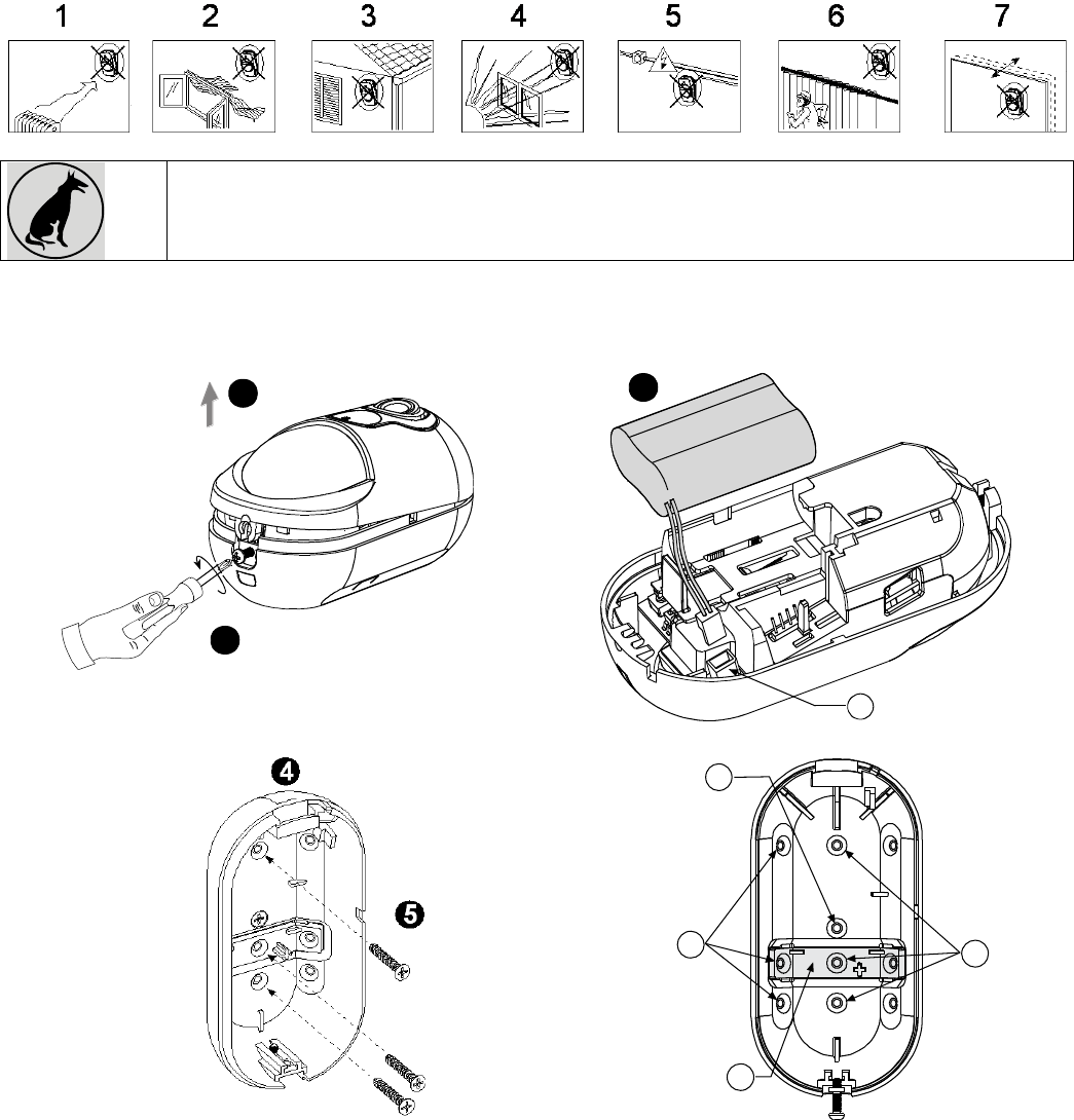
2. INSTALLATION
2.1 General Guidance (see Fig. 2)
1. Keep away from heat sources.
2. Do not expose to air drafts.
3. Do not install outdoors.
4. Avoid direct sunshine.
5. Keep wiring away from power cables.
6. Do not install behind partitions.
7. Mount on solid stable surface.
8. Installed in accordance with NEC, NFPA 70.
9. Installed in accordance with UL 681, Standard for Installations and Classifications of
burglar and Holdup Alarm Systems.
10. Installed in accordance with C22.1, Canadian Electrical Code, Part I, Safety Standard for
Electrical Installations.
WARNING! To comply with FCC and IC RF exposure compliance requirements, the PIR detector should be located at a distance of at
least 20 cm from all persons during normal operation. The antennas used for this product must not be co-located or operated in
conjunction with any other antenna or transmitter
2 D-302893 NEXT CAM PG2, NEXT CAM K9-85 PG2 Installation Instructions
Figure 2. General Guidelines
Important! The Next CAM K9-85 PG2 detector is tolerant to 38 kg (85 lb) animals moving on the floor or climbing
on furniture as long as the activity takes place below 1 m (3 ft). Above the 1 m (3 ft) height limit, the detector is
tolerant to 19 kg (42 lb) pets, but the pet immunity will decrease as the pet gets closer to the detector. It is therefore
recommended to select a mounting location that minimizes potential close proximity of animals.
2.2 Mounting
Notes:
1. Mount the detector so that its orientation is perpendicular to the expected intrusion path.
2. For installations of detector at 2m high, Dead zone is 2ft at 0m high and 0.5ft at 1.5m high.
1
2
3
A
B
C
D
E
Figure 3a. Mounting on Wall
1. Release screw
2. Remove cover from base
3. Position the battery in the battery holder and insert the battery connector terminal into the battery connector
4. Press the base against the wall at the selected mounting position and mark the drilling points through the mounting holes.
5. Drill 2 holes or 3 holes (for back tamper) and attach the base to the wall using the screws.
A. Battery connector.
B. BR-1 Knockout
C. Mounting knockouts (for surface mounting)
D. Break-away base segment (shaded)
CAUTION! THE BACK TAMPER SWITCH WILL NOT PROTECT THE UNIT UNLESS THE BREAK-AWAY BASE SEGMENT IS
SECURED TO THE WALL WITH AT LEAST ONE SCREW.
Note: Back Tamper must be enabled for UL installations.
E. Mounting knockouts (3 of 6 – for corner mounting).
D-302893 NEXT CAM PG2, NEXT CAM K9-85 PG2 Installation Instructions 3
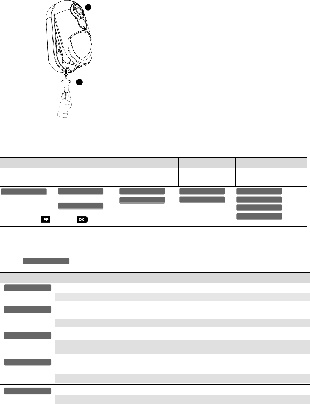
Caution!
Risk of explosion if battery is replaced by an incorrect type. Dispose of used battery according to manufacturer's instructions.
7
6
Figure 3b. Final Closure
6. Align the cover with the base.
7. Secure with screw.
2.3. Enrollment
Refer to the PowerMaster panel's Installer Guide and follow the procedure under the "02:ZONES/DEVICES" option of the Installer Menu.
A general description of the procedure is provided in the following flow chart.
Step 1
Step 2
Step 3
Step 4
Step 5
Step 6
Enter the Installer menu
and select
“02:ZONES/DEVICES”
Select "ADD NEW
DEVICE" Option
See Note [1]
Enroll the device or Enter
the device ID
Select the desired Zone
Number
Configure Location,
Zone Type &
Chime Parameters
Configure
the
Detector
means scroll and select
See Note
[2]
Notes:
[1] If the detector is already enrolled you can configure the detector parameters via the “Modify Devices” option – see Step 2.
[2] Select the "Device Settings" option and refer to section 2.4 to configure the detector parameters.
2.4. Configuring the Detector Parameters
Enter the menu and follow the configuration instructions for the Next CAM PG2 / Next CAM K9-85 PG2 PIR detector as
described in the following table.
Option
Configuration Instructions
Here you determine whether or not the alarm LED indication will be activated.
Optional settings: LED ON (default) and LED OFF.
Here you determine whether an alarm will be activated upon continued motion (low sensitivity) or upon a single
alarm event (high sensitivity)..
Optional settings: LOW sensitive (default) and HIGH sensitive.
Here you determine whether or not to set the activity time during disarm.
Optional settings: NOT Active (default), YES – no delay, YES + 5s delay, YES + 15s delay, YES + 30s delay,
YES + 1m delay, YES + 2m delay, YES + 5m delay, YES + 10m delay, YES + 20m delay and YES + 60m delay.
Note: Not applicable in this version. Do not change this setting!
Here you determine whether or not to report power failure and restore.
Optional settings: NOT connected (default) and Connected to AC.
Here you determine whether the image will be in black & white or color.
Optional settings: Black & White (default) and Color.
Image Color
AC POWER Connect
DISARM Activity
Event Counter
Alarm LED
DEVICE SETTINGS
Z10.DEV SETTINGS
Z10.SET CHIME
Z10.ZONE TYPE
Z10.LOCATION
ID No. 140-XXXX
Z10:Motion Camra
ENTR ID:XXX-XXXX
ENROLL NOW or
MODIFY DEVICES
ADD NEW DEVICES
02.ZONES/DEVICES

4 D-302893 NEXT CAM PG2, NEXT CAM K9-85 PG2 Installation Instructions
Option
Configuration Instructions
D-302893 NEXT CAM PG2, NEXT CAM K9-85 PG2 Installation Instructions 5
Option
Configuration Instructions
Here you set the pixel quality of the image. Select 160 x 120 for lower quality or 320 x 240 for higher quality..
Optional settings: 320 x 240 (default) and 160 x 120.
Here you set the brightness of the image.
Optional settings: Normal (default), -3, -2, -1, +1, +2 and +3.
Here you set the contrast of the image.
Optional settings: Normal (default), -3, -2, -1, +1, +2 and +3.
Here you determine whether or not to activate the microphone.
Optional settings: Disable (default) and Enable.
3. VIDEO VERIFICATION
After enrolling the Next CAM PG2 / Next CAM K9-85 PG2 in the PowerMaster control panel (see section 2.3 "Enrollment") and after
performing the required camera configurations through the control panel menus (see PowerMaster Installer Guide, "Configuring Motion
Cameras for Video Alarm Verification") the Next CAM PG2 / Next CAM K9-85 PG2 will capture burglary image clips to be sent to the
Monitoring Station for Burglary verification once the system is armed and upon occurrence of a burglary alarm.
The camera can also capture images upon occurrence of non-burglary alarms (i.e. Fire, Duress, Emergency and Panic) - see
PowerMaster Installer Guide, "Configuring Motion Cameras for Video Alarm Verification".
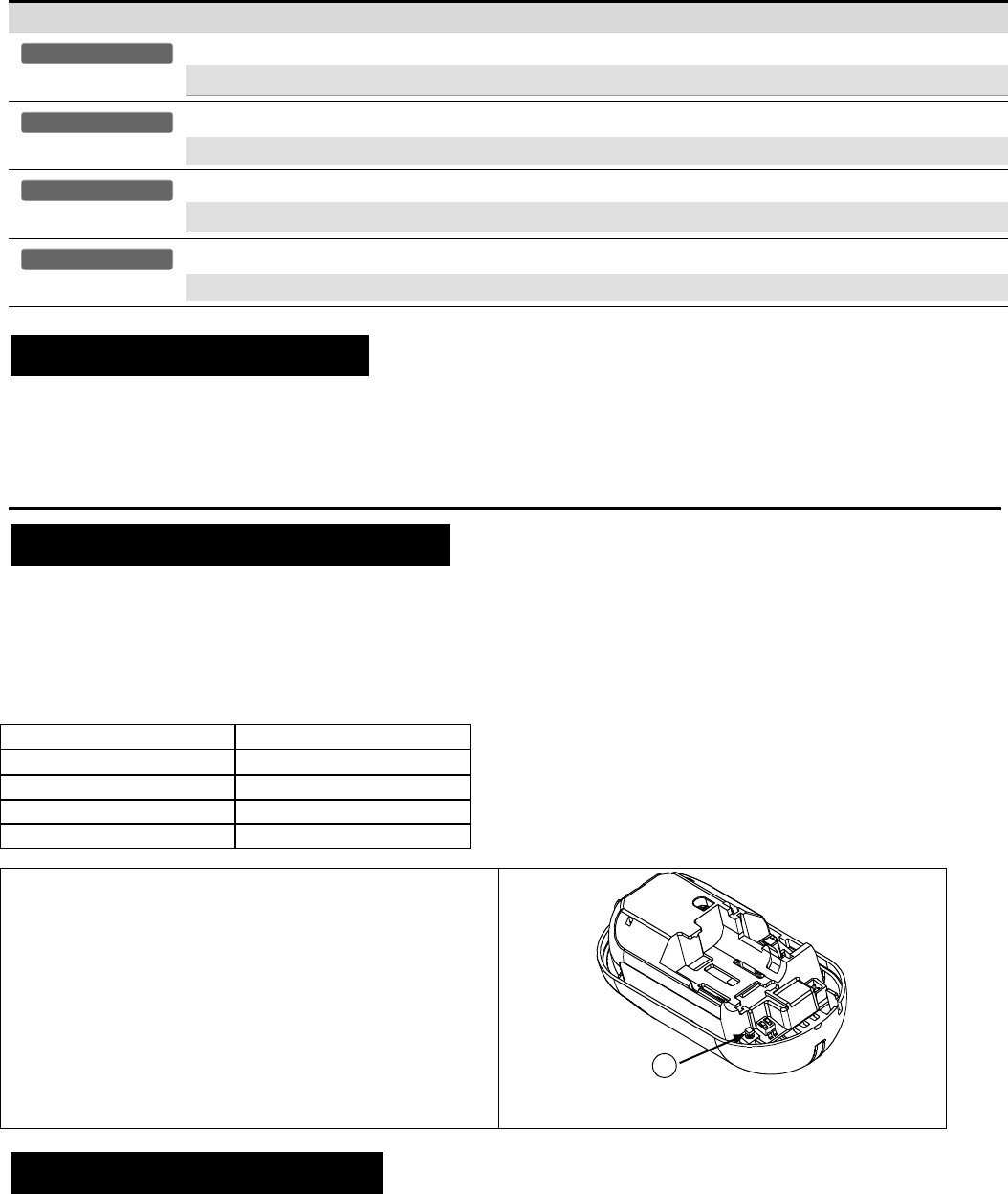
4. LOCAL DIAGNOSTICS TEST
NOTE: Run a diagnostic test at least once a year to ensure that the detector is working correctly.
A. Separate the base from the cover (see Fig. 4).
B. Put back the cover to return the tamper switch to its normal (undisturbed) position, and then secure the front cover to the base with the
case closure screw.
C. The NEXT CAM will enter a 2 min. stability period. During this time the red LED blinks.
D. Walk-test the coverage area - see Fig. 5. Walk across the far end of coverage pattern in both directions, The red LED lights each time
your motion is detected followed by 3 LED blinks.
The following table indicates received signal strength indication.
LED response
Reception
Green LED blinks
Strong
Orange LED blinks
Good
Red LED blinks
Poor
No blinks
No communication
IMPORTANT! Reliable reception must be assured. Therefore,
"poor" signal strength is not acceptable. If you receive a "poor"
signal from the detector, re-locate it and re-test until a "good" or
"strong" signal strength is received (in regions requiring UL-
compliant installation, only “strong” signal strength is permitted).
1. For detailed Diagnostics Test instructions refer to the control
panel Installer Guide.
2. For UL/CUL installations, the test result must be “Strong”.
A
A. Enroll button
Figure 4. Device enroll button
5. SPECIAL COMMENTS
Even the most sophisticated detectors can sometimes be defeated or may fail to warn due to: DC power failure / improper connection,
malicious masking of the lens, tampering with the optical system, decreased sensitivity in ambient temperatures close to that of the
human body and unexpected failure of a component part.
The above list includes the most common reasons for failure to detect intrusion, but is by no means comprehensive. It is therefore
recommended that the detector and the entire alarm system be checked weekly, to ensure proper performance.
An alarm system should not be regarded as a substitute for insurance. Home and property owners or renters should be prudent enough
to continue insuring their lives and property, even though they are protected by an alarm system.
Mic. setttings
Image Contrast
Image Brightness
Image Resolution
6 D-302893 NEXT CAM PG2, NEXT CAM K9-85 PG2 Installation Instructions
6. COMPLIANCE WITH STANDARDS
Compliance with Standards
Europe: Directive 1999/5/EC of the European Parliament. EN 50131-1 Grade 2 Class II. EN 50131-2-2, EN 50131-6
Environmental IP55.
The NEXT CAM PG2 and NEXT CAM- K9 PG2 are compatible with the RTTE requirements - Directive 1999/5/EC of the European
Parliament and of the Council of 9 March 1999 and EN50131-1 Grade 2 Class II.
Certified by the Dutch testing and certification body Telefication BV to the following standards :
EN 50131-2-2, EN 50131-6, EN 50131-5-3, EN 50130-4, and EN 50130-5.
Telefication BV has certified only the 868 MHz variant of this product.
USA: Designed to meet FCC Part 15
UK: This product is suitable for use in systems installed to conform to PD6662:2010 at Grade 2 and environmental class 2.
DD243 and BS8243
Canada: RSS 210
The Power G peripheral devices have two- way communication functionality, providing additional benefits as described in the
technical brochure. This functionality has not been tested to comply with the respective technical requirements and should
therefore be considered outside the scope of the product’s certification.
EN 50131-1 Security Grade
According to EN 50131-1:2006 and A1:2009, this equipment can be applied in installed systems up to and
including Security Grade 2.
EN 50131-1 Environmental Class
Class II
FCC Compliance Statement
This device has been tested and found to comply with the limits for a Class B digital device, pursuant to Part 15 of the FCC Rules. These limits
are designed to provide reasonable protection against harmful interference in residential installations. This equipment generates uses and can
radiate radio frequency energy and, if not installed and used in accordance with the instructions, may cause harmful interference to radio and
television reception.
However, there is no guarantee that interference will not occur in a particular installation. If this device does cause such interference, which can
be verified by turning the device off and on, the user is encouraged to eliminate the interference by one or more of the following measures:
– Re-orient or re-locate the receiving antenna.
– Increase the distance between the device and the receiver.
– Connect the device to an outlet on a circuit different from the one that supplies power to the receiver.
– Consult the dealer or an experienced radio/TV technician.
WARNING! Changes or modifications to this unit not expressly approved by the party responsible for compliance could void the user’s authority to operate the
equipment.
This device complies with FCC Rules Part 15 and with Industry Canada licence-exempt RSS standard(s). Operation is subject to two conditions: (1) This device may
not cause harmful interference, and (2) this device must accept any interference that may be received or that may cause undesired operation.
Le present appareil est conforme aux CNR d'Industrie Canada applicables aux appareils radio exempts de licence. L'exploitation est autorisee aux deux conditions
suivantes :(1) l'appareil ne doit pas produire de brouillage, et (2) l'utilisateur de l'appareil doit accepter tout brouillage radioelectrique subi, meme si le brouillage est
susceptible d'en compromettre le fonctionnement.
The technical documentation as required by the European Conformity Assessment procedure is kept at:
UNIT 6 MADINGLEY COURT CHIPPENHAM DRIVE KINGSTON MILTON KEYNES MK10 0BZ. TEL.: +44(0)845 0755800 FAX: +44(0)845 0755801
W.E.E.E. Product Recycling Declaration
For information regarding the recycling of this product you must contact the company from which you orignially purchased it. If you are discarding this product and not
returning it for repair then you must ensure that it is returned as identified by your supplier. This product is not to be thrown away with everyday waste.
Directive 2002/96/EC Waste Electrical and Electronic Equipment.
APPENDIX: SPECIFICATIONS
GENERAL
Detector Type
Dual element low-noise pyroelectric sensor
3 6 12 m0 10 20 30 40 ft
9
0
3 (10ft)
6 (20ft)
9 (30ft)
3 (10ft)
6 (20ft)
9 (30ft)
90°
3 6 9 12 m0
2.4 m
(8 ft)
10 20 30 40 ft
B
A
C
Fig. 5. Coverage Pattern & Walk-test
Lens Data
No. of Curtain Beams / curtains:
Next CAM PG2: 18 far, 18 mid, 10 close.
Next CAM K9-85 PG2: 18 far, 18 mid, 18 close.
Note: Lens – Reflex II PIR, Fresnel type lens With Optical
attenuation in the lower part of the lens. Lens material is High
Density Polyethylene (HDPE). Part of Enclosure Cover (Item 1) and
snapped to the Enclosure Base (Item 2) by two tabs and one screw.
Max. Coverage
12 x 12 m, (40 x 40 ft) / 90°
A. HORIZONTAL VIEW
B. VERTICAL VIEW
C. Next CAM PG2: 0.5-4m, Next CAM K9-85 PG2: 2-4m
Pet Immunity (Next CAM K9-85 PG2
only)
Up to 38 kg (85 lb)
ELECTRICAL
Internal Battery
6V Lithium battery (two CR-123A 3V batteries or two CR17450 3V batteries, in series) or equivalent.
Notes:
1. Use only the above battery type.
2. For UL installations use Gold Peak (GP) CR123A only.
Visonic Ltd.
M/N: RFD
FCC ID: WP3RFD
IC: 1467-RFD

D-302893 NEXT CAM PG2, NEXT CAM K9-85 PG2 Installation Instructions 7
Nominal Battery Capacity
6V 1450 mA/h (2xCR123A), 2200 mA/h (2xCR17450)
Low Battery Threshold
4.5 V
Battery Life (for typical use)
4 to 5 years (CR123A) / 8 years (CR17450)
Optional MAINS supply
Additional to batteries, 7.5 V DC
Power Supply
Type C
FUNCTIONAL
True Motion Event Verification
2 remote selections - 1 (OFF) or 2 (ON) motion events
IR Illumination
10 m (33 ft)
Picture Resolution
320x240 pixels QVGA
Frame Rate
up to 2 fps (for user)
Alarm Period
2 seconds
WIRELESS
Frequency Band (MHz)
Europe and rest of world: 433-434, 868-869 USA: 912-919
Communication Protocol
PowerG
Supervision
Signaling at 4-min. intervals
Tamper Alert
Reported when a tamper event occurs and in any subsequent message, until the tamper switch is restored
MOUNTING
Height
1.8 - 2.4 m (6 - 8 ft). For Next CAM K9-85 PG2, the recommended height is up to 2.1 m (7 ft)
Installation Options
Surface or corner
ACCESSORIES
BR-1: Surface mounted swivel bracket, adjustable 30° down and 45° left/45° right.
BR-2: BR-1 with a corner adapter
BR-3: BR-1 with a ceiling adapter
Note: UL did not evaluate the product with the use of the BR brackets
ENVIRONMENTAL
RFI Protection
>20 V/m up to 2000 MHz, excluding inband frequencies
Operating Temperatures
-10°C to 50°C (14°F to 122°F) indoor
Note: UL tested 0°C to 49°C
Storage Temperatures
-20°C to 60°C (-4°F to 140°F)
Humidity
Average relative humidity of up to approximately 75% non-condensing. For 30 days per year the relative humidity may vary
between 85 % and 95 % non-condensing
Note: For UL installations, relative humidity is 85%.
PHYSICAL
Size (H x W x D)
125 x 63 x 60 mm (4-15/16 x 2-1/2 x 2-3/8”).
Weight (with battery)
200 g (7 oz).
Color
White
PATENTS
U.S. Patents 5,693,943 6,211,522 D445,709 (another patent pending)
WARRANTY
Visonic Limited (the “Manufacturer") warrants this product only (the "Product") to the original purchaser only (the
“Purchaser”) against defective workmanship and materials under normal use of the Product for a period of
twelve (12) months from the date of shipment by the Manufacturer.
This Warranty is absolutely conditional upon the Product having been properly installed, maintained and
operated under conditions of normal use in accordance with the Manufacturers recommended installation and
operation instructions. Products which have become defective for any other reason, according to the
Manufacturers discretion, such as improper installation, failure to follow recommended installation and
operational instructions, neglect, willful damage, misuse or vandalism, accidental damage, alteration or
tampering, or repair by anyone other than the manufacturer, are not covered by this Warranty.
The Manufacturer does not represent that this Product may not be compromised and/or circumvented or that the
Product will prevent any death and/or personal injury and/or damage to property resulting from burglary,
robbery, fire or otherwise, or that the Product will in all cases provide adequate warning or protection. The
Product, properly installed and maintained, only reduces the risk of such events without warning and it is not a
guarantee or insurance that such events will not occur.
THIS WARRANTY IS EXCLUSIVE AND EXPRESSLY IN LIEU OF ALL OTHER WARRANTIES,
OBLIGATIONS OR LIABILITIES, WHETHER WRITTEN, ORAL, EXPRESS OR IMPLIED, INCLUDING ANY
WARRANTY OF MERCHANTABILITY OR FITNESS FOR A PARTICULAR PURPOSE, OR OTHERWISE. IN
NO CASE SHALL THE MANUFACTURER BE LIABLE TO ANYONE FOR ANY CONSEQUENTIAL OR
INCIDENTAL DAMAGES FOR BREACH OF THIS WARRANTY OR ANY OTHER WARRANTIES
WHATSOEVER, AS AFORESAID.
THE MANUFACTURER SHALL IN NO EVENT BE LIABLE FOR ANY SPECIAL, INDIRECT, INCIDENTAL,
CONSEQUENTIAL OR PUNITIVE DAMAGES OR FOR LOSS, DAMAGE, OR EXPENSE, INCLUDING LOSS
OF USE, PROFITS, REVENUE, OR GOODWILL, DIRECTLY OR INDIRECTLY ARISING FROM
PURCHASER’S USE OR INABILITY TO USE THE PRODUCT, OR FOR LOSS OR DESTRUCTION OF
OTHER PROPERTY OR FROM ANY OTHER CAUSE, EVEN IF MANUFACTURER HAS BEEN ADVISED OF
THE POSSIBILITY OF SUCH DAMAGE.
THE MANUFACTURER SHALL HAVE NO LIABILITY FOR ANY DEATH, PERSONAL AND/OR BODILY
INJURY AND/OR DAMAGE TO PROPERTY OR OTHER LOSS WHETHER DIRECT, INDIRECT,
INCIDENTAL, CONSEQUENTIAL OR OTHERWISE, BASED ON A CLAIM THAT THE PRODUCT FAILED TO
FUNCTION.
However, if the Manufacturer is held liable, whether directly or indirectly, for any loss or damage arising under
this limited warranty, THE MANUFACTURER'S MAXIMUM LIABILITY (IF ANY) SHALL NOT IN ANY CASE
EXCEED THE PURCHASE PRICE OF THE PRODUCT, which shall be fixed as liquidated damages and not as
a penalty, and shall be the complete and exclusive remedy against the Manufacturer.
When accepting the delivery of the Product, the Purchaser agrees to the said conditions of sale and warranty
and he recognizes having been informed of.
Some jurisdictions do not allow the exclusion or limitation of incidental or consequential damages, so these
limitations may not apply under certain circumstances.
The Manufacturer shall be under no liability whatsoever arising out of the corruption and/or malfunctioning of
any telecommunication or electronic equipment or any programs.
The Manufacturers obligations under this Warranty are limited solely to repair and/or replace at the
Manufacturer’s discretion any Product or part thereof that may prove defective. Any repair and/or replacement
shall not extend the original Warranty period. The Manufacturer shall not be responsible for dismantling and/or
reinstallation costs. To exercise this Warranty the Product must be returned to the Manufacturer freight pre-paid
and insured. All freight and insurance costs are the responsibility of the Purchaser and are not included in this
Warranty.
This warranty shall not be modified, varied or extended, and the Manufacturer does not authorize any person to
act on its behalf in the modification, variation or extension of this warranty. This warranty shall apply to the
Product only. All products, accessories or attachments of others used in conjunction with the Product, including
batteries, shall be covered solely by their own warranty, if any. The Manufacturer shall not be liable for any
damage or loss whatsoever, whether directly, indirectly, incidentally, consequentially or otherwise, caused by the
malfunction of the Product due to products, accessories, or attachments of others, including batteries, used in
conjunction with the Products. This Warranty is exclusive to the original Purchaser and is not assignable.
This Warranty is in addition to and does not affect your legal rights. Any provision in this warranty which is
contrary to the Law in the state or country were the Product is supplied shall not apply.
Warning: The user must follow the Manufacturer’s installation and operational instructions including testing the
Product and its whole system at least once a week and to take all necessary precautions for his/her safety and
the protection of his/her property.
1/08

8 D-302893 NEXT CAM PG2, NEXT CAM K9-85 PG2 Installation Instructions
EMAIL: info@visonic.com
INTERNET: www.visonic.com
VISONIC LTD. 2014 D-302893 NEXT CAM PG2, NEXT CAM K9-85 PG2 (Rev 45, 110/14)
D-303372 TOWER-30AM PG2, TOWER-30AM K9-90 PG2 Installation Instructions 1
TOWER-30AM PG2 /
TOWER-30AM K9-90 PG2
Wireless PowerG High-security Mirror Detector with Anti-
masking
Installation Instructions
1. INTRODUCTION
The TOWER-30AM PG2 and TOWER-30AM K9-90 PG2 (pet-immune) are 2-way, microprocessor-
controlled, wireless digital mirror PIR detectors which include the following features:
For use with all PowerMaster® control panels (version 13 and higher).
Adaptive Active Infra-Red Anti-Masking technology providing the most advanced reliable protection against
intentional masking attempts (patent pending)
Includes a fully supervised PowerG transceiver.
Incorporates patent pending black mirrors for extremely high white light immunity.
Advanced elliptical / parabolic mirror technology (patented)
V-slot® optic technology (patented) for improved robustness, anti-vandalism and for very high
reliability.
Creep zone protection
TOWER-30AM K9-90 PG2 can distinguish between human beings and pets weighing up to 40 kg (90 lb).
The advanced True Motion Recognition™ algorithm (patented) allows distinguishing between the true
motion of an intruder and any other disturbances which may cause false alarms.
Built-in link quality indicators; no need for the installer to physically approach the control panel thus
making installation faster and easier.
No vertical adjustment is needed.
Motion event counter determines whether 1 or 2 consecutive motion events will trigger an alarm.
Automatic termination of walk-test after 15 minutes.
Microprocessor-controlled temperature compensation.
Sealed chamber protects the optical system.
Front and back tamper protection.
Self-test
Notes: 1. The pet immunity and creep zone protection were not evaluated by UL.
2. For CE installations, the pet immunity was not evaluated by DNV.
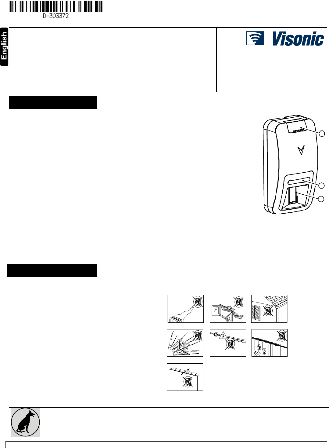
C
B
A
A. Screw cover
B. LED
C. PIR optical window
Figure 1. General View
2. INSTALLATION
2.1 General Guidance (see Fig. 2)
1. Keep away from heat sources.
2. Do not expose to air drafts.
3. Do not install outdoors.
4. Avoid direct sunshine.
5. Keep wiring away from power cables.
6. Do not install behind partitions.
7. Mount on solid stable surface.
Installed in accordance with NEC, NFPA 70.
Installed in accordance with UL 681, Standard
for Installations and Classifications of burglar
and Holdup Alarm Systems.
Installed in accordance with C22.1, Canadian
Electrical Code, Part I, Safety Standard for
Electrical Installations
1 2 3
4 5 6
7
Figure 2. General Guidelines
Important! The detector is immune to 40 kg (90 lb) animals moving on the floor or climbing on furniture as long as the
activity takes place below 1 m (3 ft). Above the 1 m (3 ft) height limit, the detector is immune to 9 kg (20 lb) pets, but the
pet immunity will decrease as the pet gets closer to the detector. It is therefore recommended to select a mounting location
that minimizes potential close proximity of animals.
WARNING! To comply with FCC and IC RF exposure compliance requirements, the PIR detector should be located at a distance of at least 20

2 D-303372 TOWER-30AM PG2, TOWER-30AM K9-90 PG2 Installation Instructions
cm from all persons during normal operation. The antennas used for this product must not be co-located or operated in conjunction with any
other antenna or transmitter
D-303372 TOWER-30AM PG2, TOWER-30AM K9-90 PG2 Installation Instructions 3
2.2 Mounting
Notes:
1. Mount the detector so that its orientation is perpendicular to the expected intrusion path.
2. For installations of detector at 2m high, Dead zone is 2ft at 0m high and 0.5ft at 1.5m high.
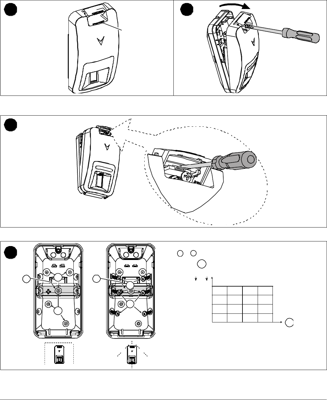
1
2
1. On the indicated location, lift the screw cover upward using your
thumb.
2. Release the screw and open the cover in the direction
shown by the arrow.
3
3. Insert a screwdriver into the slot and then push inward to separate the base from the cover.
4
a
b
C
a
b
C
Note: For the desired detector's range and height, use mounting
holes
a
or
b
, as specified in the table.
6 1.8
7 2.1
8 2.4
9 2.7
10 3.0
ft m
b
a
b
b
a
a
b
b
a
a
a
b
b
b
b
b
15
6
30
9
45
12
60 ft
15 m
A
B
a – upper surface (without downward tilt)
b – lower surface (with downward tilt)
4. Set the desired detector range.
A. Mounting height
B. Coverage range
C. Break-away base segment (shaded)
4 D-303372 TOWER-30AM PG2, TOWER-30AM K9-90 PG2 Installation Instructions
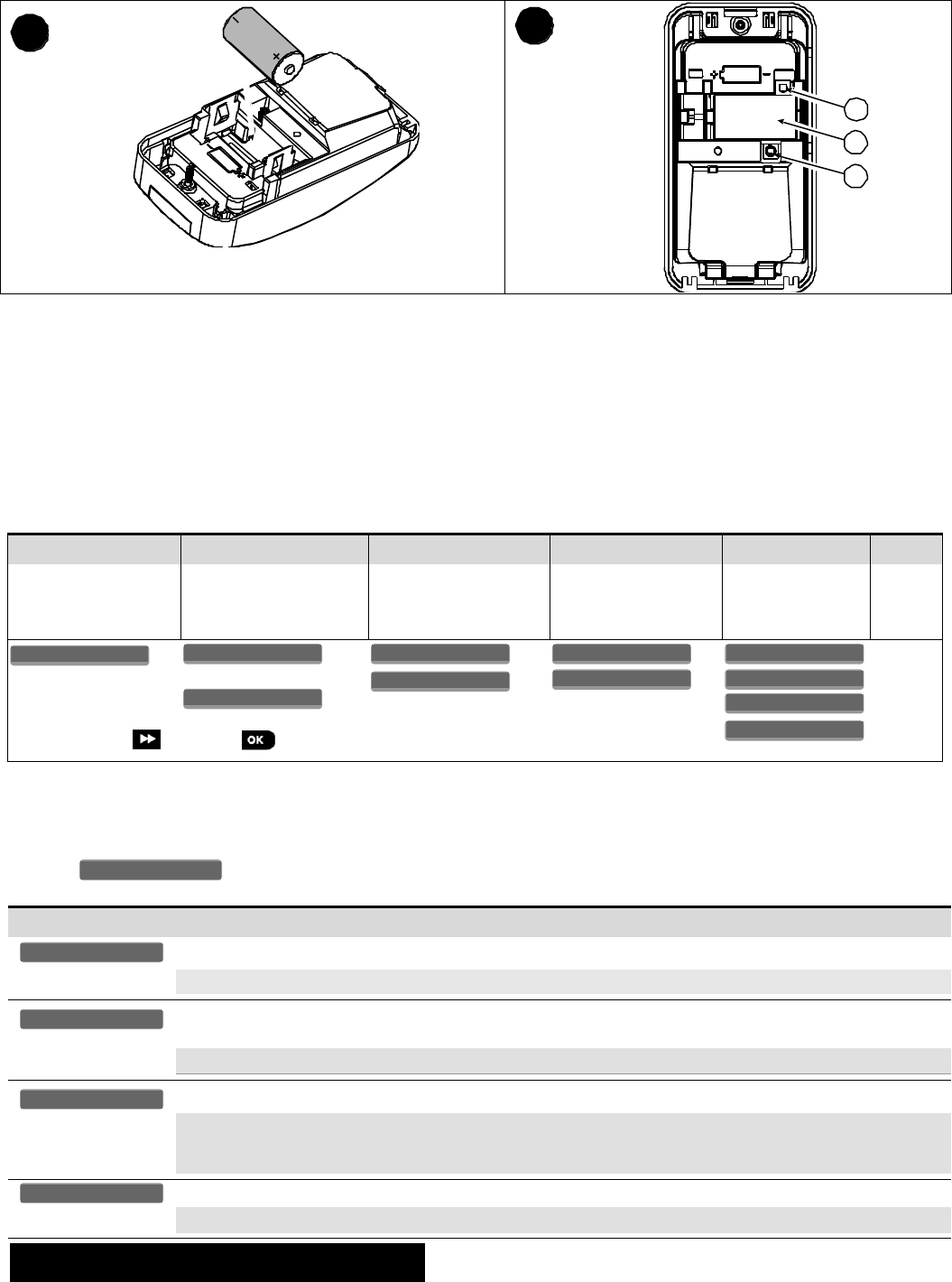
5
6
D
E
F
5. Insert battery while observing polarity.
D. Enroll button (use a screwdriver to press the recessed button)
E. Battery
F. Tamper switch
CAUTION! THE BACK TAMPER SWITCH WILL NOT PROTECT THE UNIT UNLESS THE BREAK-AWAY BASE SEGMENT IS
SECURED TO THE WALL WITH AT LEAST ONE SCREW.
CAUTION! RISK OF EXPLOSION IF BATTERY IS REPLACED BY AN INCORRECT TYPE. DISPOSE OF USED BATTERY
ACCORDING TO MANUFACTURER'S INSTRUCTIONS.
Note: Back Tamper must be enabled for UL installations.
Figure 3. Mounting
2.3. Enrollment
Refer to the PowerMaster control panel's Installer Guide and follow the procedure under the "02:ZONES/DEVICES" option of the
Installer Menu. A general description of the procedure is provided in the following flow chart.
Step 1
Step 2
Step 3
Step 4
Step 5
Step 6
Enter the Installer menu
and select
“02:ZONES/DEVICES”
Select "ADD NEW
DEVICE" Option
See Note [1]
Enroll the device or Enter
the device ID
Select the desired Zone
Number
Configure
Location, Zone
Type & Chime
Parameters
Configure
the
Detector
means scroll and select
See Note
[2]
Notes:
[1] If the detector is already enrolled you can configure the detector parameters via the “Modify Devices” option – see Step 2.
[2] Select the "Device Settings" option and refer to section 2.4 to configure the detector parameters.
2.4. Configuring the Detector Parameters
Enter the menu and follow the configuration instructions for the TOWER-30AM PG2 PIR detector as described in
the following table.
Option
Configuration Instructions
Define whether or not the alarm LED indication will be activated.
Optional settings: LED ON (default) and LED OFF.
Define whether an alarm will be activated upon continued motion (low sensitivity) or upon a single alarm event
(high sensitivity).
Optional settings: LOW sensitive (default) and HIGH sensitive.
Define whether or not to set the activity time during disarm.
Optional settings: NOT Active (default), YES – no delay, YES + 5s delay, YES + 15s delay, YES + 30s delay,
YES + 1m delay, YES + 2m delay, YES + 5m delay, YES + 10m delay, YES + 20m delay and YES + 60m
delay.
Define the activity and the sensitivity level of the anti-masking.
Optional settings: LOW sensitive (default), HIGH sensitive and disabled.
3. LOCAL DIAGNOSTICS TEST
NOTE: Run a diagnostic test at least once a year to ensure that the detector is working correctly.
A. Separate the base from the cover (see Fig. 3).
ANTI MASKING-AM
DISARM Activity
Event Counter
Alarm LED
DEVICE SETTINGS
Z14.DEV SETTINGS
Z14.SET CHIME
Z14.ZONE TYPE
Z14.LOCATION
ID No. 123-XXXX
Z14:Motion Sens
ENTR ID:XXX-XXXX
ENROLL NOW or
MODIFY DEVICES
ADD NEW DEVICES
02.ZONES/DEVICES
D-303372 TOWER-30AM PG2, TOWER-30AM K9-90 PG2 Installation Instructions 5
B. Put back the cover to return the tamper switch to its normal (undisturbed) position, and then secure the front cover to the base with the
case closure screw.
C. The TOWER-30AM PG2 will enter a 2 min. stability period. During this time the red LED blinks.
D. Walk-test the coverage area - see Figure 4. Walk across the far end of coverage pattern in both directions; the red LED lights each
time your motion is detected followed by 3 LED blinks.
The following table indicates the received signal strength indication.
LED response
Reception
Green LED blinks
Strong
Orange LED blinks
Good
Red LED blinks
Poor
No blinks
No communication
IMPORTANT! Reliable reception must be assured. Therefore, "poor" signal strength is not acceptable. If you receive a "poor" signal
from the detector, re-locate it and re-test until a "good" or "strong" signal strength is received (in regions requiring UL-compliant
installation, only “strong” signal strength is permitted).
1. For detailed Diagnostics Test instructions refer to the control panel Installer Guide.
2. For UL/CUL installations, the test result must be “Strong”.
4. EVENT INDICATIONS
LED Indications
Event
Red LED blinks
Stabilization (warm-up 120 sec)
Red LED ON 0.2 sec.
Tamper open / close
Red on 2 sec.
Intruder alarm
Yellow LED on
AM detection – diagnostic mode
Yellow LED blinks slowly (0.2 sec. ON, 30 sec. OFF)
AM detection – Normal mode
Yellow and red LED blink simultaneously (0.2 sec. ON [both], 0.2 sec. OFF)
Self-test failure – Diagnostic mode
Yellow and red LED blink simultaneously slowly (0.2 sec. ON [both], 30 sec. OFF)
Self-test failure – Normal mode
5. SPECIAL COMMENTS
Even the most sophisticated detectors can sometimes be defeated or may fail to warn due to: DC power failure / improper connection,
malicious masking of the lens, tampering with the optical system, decreased sensitivity in ambient temperatures close to that of the
human body and unexpected failure of a component part.
The above list includes the most common reasons for failure to detect intrusion, but is by no means comprehensive. It is therefore
recommended that the detector and the entire alarm system be checked weekly, to ensure proper performance.
An alarm system should not be regarded as a substitute for insurance. Home and property owners or renters should be prudent enough
to continue insuring their lives and property, even though they are protected by an alarm system.
6. COMPLIANCE WITH STANDARDS
Europe (CE): EN 50131-1, EN 300220, EN 301489, EN 60950, EN 50130-4, EN 50130-5,
EN 50131-2-2 Grade 3 Class II, EN 50131-6
The TOWER-30 AM PG2 and TOWER-30 AM K9-90 PG2 are compatible with the RTTE requirements -
Directive 1999/5/EC of the European Parliament and of the Council of 9 March 1999.
Certified by the Dutch testing and certification body Telefication BV to the following standards :
EN 50131-2-2, EN 50131-6, EN 50131-5-3, EN 50130-4, and EN 50130-5.
Telefication BV has certified only the 868 MHz variant of this product.
UK: This product is suitable for use in systems installed to conform to PD6662:2010 in accordance
with EN 50131-2-2 security Grade 3 and environmental Class 2. DD243 and BS8243
USA: CFR 47 Part 15 (FCC)
Canada: RSS 210
The Power G peripheral devices have two- way communication functionality, providing additional benefits as described in the
technical brochure. This functionality has not been tested to comply with the respective technical requirements and should
therefore be considered outside the scope of the product’s certification.
EN 50131-1 Security Grade
According to EN 50131-1:2006 and A1:2009, this equipment can be applied in installed systems up to
and including Security Grade 2.
EN 50131-1 Environmental
Class
Class II
FCC Compliance Statement
Visonic Ltd.
M/N: RFD
FCC ID: WP3RFD
IC: 1467-RFD
6 D-303372 TOWER-30AM PG2, TOWER-30AM K9-90 PG2 Installation Instructions
This device has been tested and found to comply with the limits for a Class B digital device, pursuant to Part 15 of the FCC Rules. These
limits are designed to provide reasonable protection against harmful interference in residential installations. This equipment generates
uses and can radiate radio frequency energy and, if not installed and used in accordance with the instructions, may cause harmful
interference to radio and television reception.
However, there is no guarantee that interference will not occur in a particular installation. If this device does cause such interference,
which can be verified by turning the device off and on, the user is encouraged to eliminate the interference by one or more of the
following measures:
– Re-orient or re-locate the receiving antenna.
– Increase the distance between the device and the receiver.
– Connect the device to an outlet on a circuit different from the one that supplies power to the receiver.
– Consult the dealer or an experienced radio/TV technician.
WARNING! Changes or modifications to this unit not expressly approved by the party responsible for compliance could void the user’s
authority to operate the equipment.
This device complies with FCC Rules Part 15 and with Industry Canada license-exempt RSS standard(s). Operation is subject to two
conditions: (1) This device may not cause harmful interference, and (2) this device must accept any interference that may be received
or that may cause undesired operation.
Le present appareil est conforme aux CNR d'Industrie Canada applicables aux appareils radio exempts de licence. L'exploitation est
autorisee aux deux conditions suivantes :(1) l'appareil ne doit pas produire de brouillage, et (2) l'utilisateur de l'appareil doit accepter
tout brouillage radioelectrique subi, meme si le brouillage est susceptible d'en compromettre le fonctionnement.
The technical documentation as required by the European Conformity Assessment procedure is kept at:
UNIT 6 MADINGLEY COURT CHIPPENHAM DRIVE KINGSTON MILTON KEYNES MK10 0BZ. TEL.: +44(0)845 0755800 FAX: +44(0)845 0755801
W.E.E.E. Product Recycling Declaration
For information regarding the recycling of this product you must contact the company from which you orignially purchased it. If you are discarding this product and not
returning it for repair then you must ensure that it is returned as identified by your supplier. This product is not to be thrown away with everyday waste.
Directive 2002/96/EC Waste Electrical and Electronic Equipment.
APPENDIX: SPECIFICATIONS
GENERAL
Detector Type
Dual element low-noise pyroelectric sensor
Mirror Data
No. of Beam Elements:
18x3=54 far parabolic mirror segments
Note: Window material is High Density Polyethylene (HDPE). The window is part of the
Enclosure Cover (Item 1).
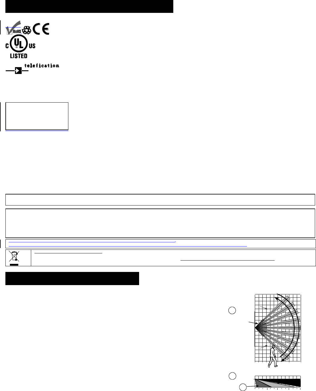
Max. Coverage
15 m (49 ft) / 90°
A. Horizontal view
B. Vertical view
Figure 4. Coverage Pattern & Walk-test
Pet Immunity (only)
Up to 40 kg (90 lb)
ELECTRICAL
Power Supply
Type C
Internal Battery
3V Lithium battery, type CR-123A or equivalent (optionally can be used type CR17450)
Notes:
1. Use only the above battery type.
2. For UL installations use Gold Peak (GP) CR123A only.
Nominal Battery Capacity
1450 mA/h ( 2400mA/h for optional CR17450)
Low Battery Threshold
2.45 V
Battery Life (for typical use)
6.5 years
FUNCTIONAL
True Motion Event Verification
2 remote selections - 1 (OFF) or 2 (ON) motion events
Alarm Period
2 seconds

D-303372 TOWER-30AM PG2, TOWER-30AM K9-90 PG2 Installation Instructions 7
WIRELESS
Frequency Band (MHz)
Europe and rest of world: 433-434, 868-869 USA: 912-919
Communication Protocol
PowerG
Supervision
Signaling at 4-min. intervals
Tamper Alert
Reported when a tamper event occurs and in any subsequent message, until the tamper
switch is restored
MOUNTING
Height
1.8 – 3.0 m (6 - 10 ft).
Installation Options
Surface or corner
ACCESSORIES
BR-1: Surface mounted swivel bracket, adjustable 30° down and 45° left/45° right.
BR-2: BR-1 with a corner adapter
BR-3: BR-1 with a ceiling adapter
Notes:
1. UL did not evaluate the product with the use of the BR brackets.
2. The mounting bracket was not tested and not certified according to Belgium TO14A
requirements.
ENVIRONMENTAL
RFI Protection
>20 V/m up to 2000 MHz, excluding inband frequencies
Operating Temperatures
-10°C to 50°C (14°F to 122°F) indoor
Note: UL tested 0°C to 49°C
Storage Temperatures
-20°C to 60°C (-4°F to 140°F)
Humidity
Average relative humidity of up to approximately 75% non-condensing. For 30 days per
year the relative humidity may vary between 85 % and 95 % non-condensing
Note: For UL installations, relative humidity is 85%.
PHYSICAL
Size (H x W x D)
115 x 60 x 48 mm (4-1/2 x 2-5/16 x 1-15/16”)
Weight (with battery)
90 g (3 oz).
Color
White
PATENTS
U.S. Patents 5,693,943 6,211,522 D445,709 (another patent pending)
WARRANTY
Visonic Limited (the “Manufacturer") warrants this product only (the "Product") to the original purchaser only (the
“Purchaser”) against defective workmanship and materials under normal use of the Product for a period of
twelve (12) months from the date of shipment by the Manufacturer.
This Warranty is absolutely conditional upon the Product having been properly installed, maintained and
operated under conditions of normal use in accordance with the Manufacturers recommended installation and
operation instructions. Products which have become defective for any other reason, according to the
Manufacturers discretion, such as improper installation, failure to follow recommended installation and
operational instructions, neglect, willful damage, misuse or vandalism, accidental damage, alteration or
tampering, or repair by anyone other than the manufacturer, are not covered by this Warranty.
The Manufacturer does not represent that this Product may not be compromised and/or circumvented or that the
Product will prevent any death and/or personal injury and/or damage to property resulting from burglary,
robbery, fire or otherwise, or that the Product will in all cases provide adequate warning or protection. The
Product, properly installed and maintained, only reduces the risk of such events without warning and it is not a
guarantee or insurance that such events will not occur.
THIS WARRANTY IS EXCLUSIVE AND EXPRESSLY IN LIEU OF ALL OTHER WARRANTIES,
OBLIGATIONS OR LIABILITIES, WHETHER WRITTEN, ORAL, EXPRESS OR IMPLIED, INCLUDING ANY
WARRANTY OF MERCHANTABILITY OR FITNESS FOR A PARTICULAR PURPOSE, OR OTHERWISE. IN
NO CASE SHALL THE MANUFACTURER BE LIABLE TO ANYONE FOR ANY CONSEQUENTIAL OR
INCIDENTAL DAMAGES FOR BREACH OF THIS WARRANTY OR ANY OTHER WARRANTIES
WHATSOEVER, AS AFORESAID.
THE MANUFACTURER SHALL IN NO EVENT BE LIABLE FOR ANY SPECIAL, INDIRECT, INCIDENTAL,
CONSEQUENTIAL OR PUNITIVE DAMAGES OR FOR LOSS, DAMAGE, OR EXPENSE, INCLUDING LOSS
OF USE, PROFITS, REVENUE, OR GOODWILL, DIRECTLY OR INDIRECTLY ARISING FROM
PURCHASER’S USE OR INABILITY TO USE THE PRODUCT, OR FOR LOSS OR DESTRUCTION OF
OTHER PROPERTY OR FROM ANY OTHER CAUSE, EVEN IF MANUFACTURER HAS BEEN ADVISED OF
THE POSSIBILITY OF SUCH DAMAGE.
THE MANUFACTURER SHALL HAVE NO LIABILITY FOR ANY DEATH, PERSONAL AND/OR BODILY
INJURY AND/OR DAMAGE TO PROPERTY OR OTHER LOSS WHETHER DIRECT, INDIRECT,
INCIDENTAL, CONSEQUENTIAL OR OTHERWISE, BASED ON A CLAIM THAT THE PRODUCT FAILED TO
FUNCTION.
However, if the Manufacturer is held liable, whether directly or indirectly, for any loss or damage arising under
this limited warranty, THE MANUFACTURER'S MAXIMUM LIABILITY (IF ANY) SHALL NOT IN ANY CASE
EXCEED THE PURCHASE PRICE OF THE PRODUCT, which shall be fixed as liquidated damages and not as
a penalty, and shall be the complete and exclusive remedy against the Manufacturer.
When accepting the delivery of the Product, the Purchaser agrees to the said conditions of sale and warranty
and he recognizes having been informed of.
Some jurisdictions do not allow the exclusion or limitation of incidental or consequential damages, so these
limitations may not apply under certain circumstances.
The Manufacturer shall be under no liability whatsoever arising out of the corruption and/or malfunctioning of
any telecommunication or electronic equipment or any programs.
The Manufacturers obligations under this Warranty are limited solely to repair and/or replace at the
Manufacturer’s discretion any Product or part thereof that may prove defective. Any repair and/or replacement
shall not extend the original Warranty period. The Manufacturer shall not be responsible for dismantling and/or
reinstallation costs. To exercise this Warranty the Product must be returned to the Manufacturer freight pre-paid
and insured. All freight and insurance costs are the responsibility of the Purchaser and are not included in this
Warranty.
This warranty shall not be modified, varied or extended, and the Manufacturer does not authorize any person to
act on its behalf in the modification, variation or extension of this warranty. This warranty shall apply to the
Product only. All products, accessories or attachments of others used in conjunction with the Product, including
batteries, shall be covered solely by their own warranty, if any. The Manufacturer shall not be liable for any
damage or loss whatsoever, whether directly, indirectly, incidentally, consequentially or otherwise, caused by the
malfunction of the Product due to products, accessories, or attachments of others, including batteries, used in
conjunction with the Products. This Warranty is exclusive to the original Purchaser and is not assignable.
This Warranty is in addition to and does not affect your legal rights. Any provision in this warranty which is
contrary to the Law in the state or country were the Product is supplied shall not apply.
Warning: The user must follow the Manufacturer’s installation and operational instructions including testing the
Product and its whole system at least once a week and to take all necessary precautions for his/her safety and
the protection of his/her property.
1/08
EMAIL: info@visonic.com
INTERNET: www.visonic.com
VISONIC LTD. 20134 D-303372 TOWER-30AM PG2, TOWER-30AM K9-90 PG2 (REV. 45, 10/1314)