Visonic TOWERCAMPG2 PowerG, Outdoor Mirror PIR Motion Detector User Manual D 304493 TOWER CAM PG2 Installation Instructions
Visonic Ltd. PowerG, Outdoor Mirror PIR Motion Detector D 304493 TOWER CAM PG2 Installation Instructions
Visonic >
Users Manual
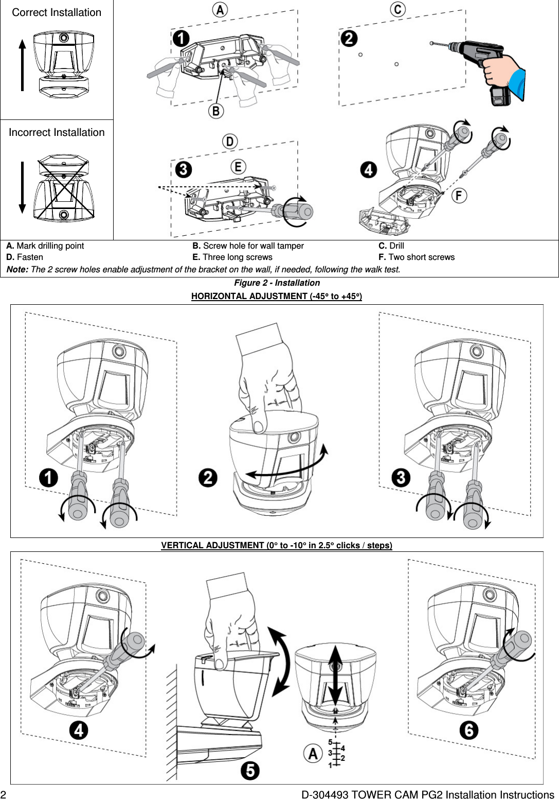
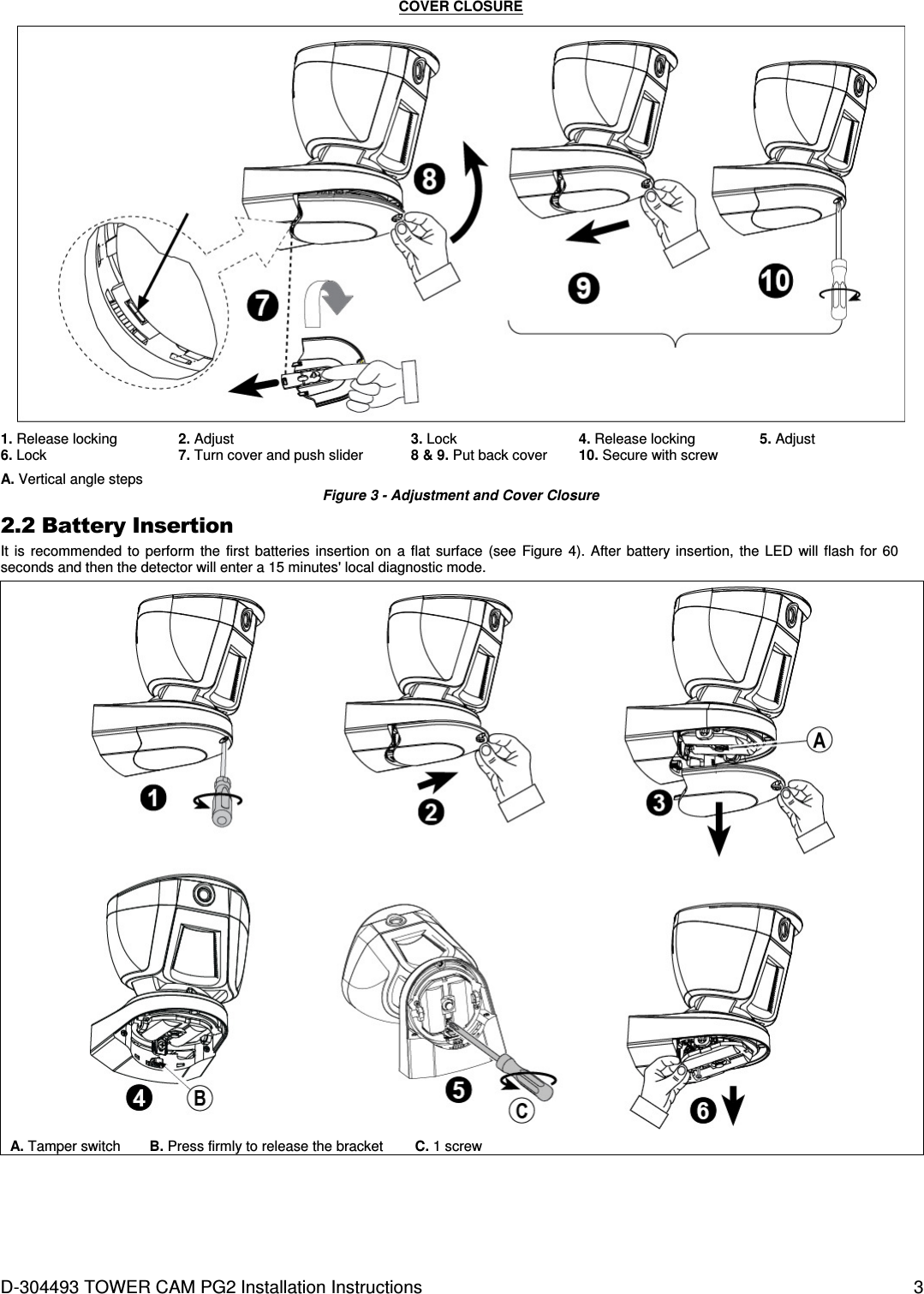
![4 D-304493 TOWER CAM PG2 Installation Instructions Steps 7 and 8 are optional for external 7.5 VDC power connection D. Snap the terminal block into place. Caution! Risk of explosion if battery is replaced by an incorrect type. Dispose of used battery according to the manufacturer's instructions. Figure 4 – Battery Insertion 2.3. Enrollment Refer to the PowerMaster control panel's Installer Guide and follow the procedure under the "02:ZONES/DEVICES" option of the Installer Menu. A general description of the procedure is provided in the following flow chart. Step 1 Step 2 Step 3 Step 4 Enter the Installer menu and select “02:ZONES/DEVICES” Select "ADD NEW DEVICE" See Note 1 Enroll the device (see Figure 5) or enter the device ID Select a detector number for the new flood detector 02:ZONES/DEVICES ADD NEW DEVICES ENROLL NOW or ENTR ID:XXX-XXXX Z09:Motion Camra ID No. 142-XXXX MODIFY DEVICES Step 5 Step 6 Step 7 Configure Location, Zone Type & Chime parameters Enter PARTITIONS. See Note 2 Assign partitions to the detector by pressing the , and/or buttons on the panel Z09.LOCATION Z09.ZONE TYPE Z09.SET CHIME Z09/PARTITIONS Z09:P1 P2 P3 means scroll and select Notes: [1] If the detector is already enrolled you can configure the detector parameters and assign partitions via the “Modify Devices” option – see Step 2. [2] PARTITIONS will appear only if PARTITIONING was previously enabled in a panel that supports the Partitioning feature (for further details, see "Partitioning" in the PowerMaster Installer Guide).](https://usermanual.wiki/Visonic/TOWERCAMPG2/User-Guide-2365515-Page-4.png)