Vix Technology CP6100 CP6100 card processor on-board validator User Manual
Vix Technology (Aust) Pty Ltd CP6100 card processor on-board validator
UserManual.wiki
>
Vix Technology
>
CP6100 User Manual
User Manual
Navigation menu
Upload a User Manual
Namespaces
Wiki Guide
HTML
PDF
Info
Views
User Manual
Discussion / Help
Navigation
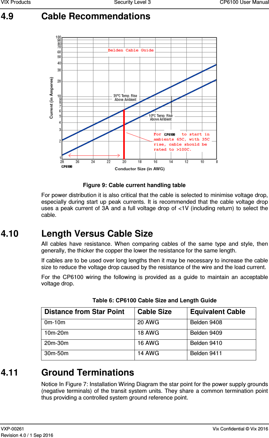
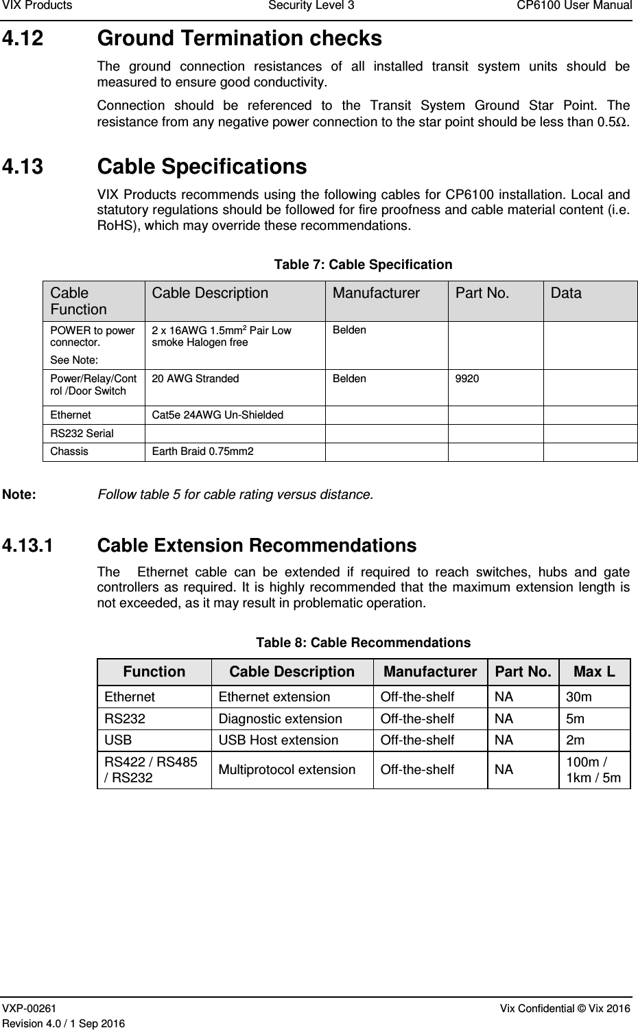
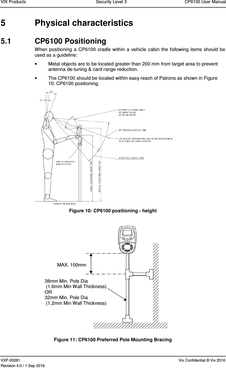
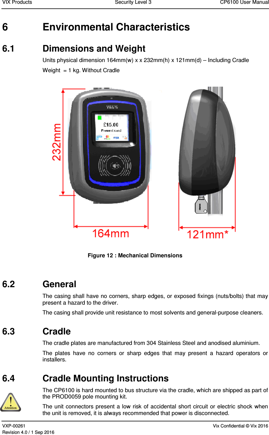
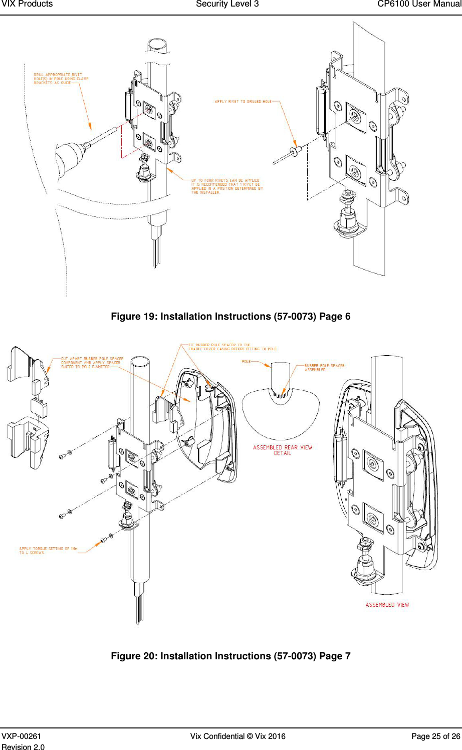
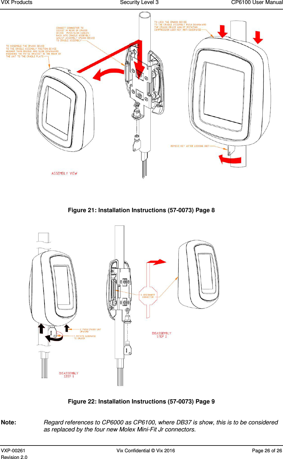
![VIX Products Security Level 3 CP6100 User Manual VXP-00261 Vix Confidential © Vix 2016 Page 8 of 26 Revision 4.0 2.3 References The following materials are to be used in conjunction with or are referenced by this document. [1] VXP-00240 CP6100 Manufacturing Pack [2] VXP-00212 CP6100 Production Test Plan [3] VXP-00241 CP6100 Build Instructions](https://usermanual.wiki/Vix-Technology/CP6100/User-Guide-3150572-Page-8.png)