Vix Technology CP6100 CP6100 card processor on-board validator User Manual
Vix Technology (Aust) Pty Ltd CP6100 card processor on-board validator
User Manual

This material is confidential to Vix and may not be disclosed in whole or in part to any third party nor used in any
manner whatsoever other than for the purposes expressly consented to by Vix in writing.
This material is also copyright and may not be reproduced, stored in a retrieval system or transmitted in any form or
by any means in whole or in part without the express written consent of Vix.
VIX Products
CP6100 User Manual
Document No: VXP-00261 Category: 433 Revision: 4.0
VIXP
Approvals Author Hardware Leader Product Manager
Name: Mike Hanssen Daniel Matthews Peter Bouhlas
Signature:
Date:

VIX Products Security Level 3 CP6100 User Manual
VXP-00261 Vix Confidential © Vix 2016 Page 2 of 26
Revision 4.0
Document History
Revision
Revision
Date Description Author
0.1 7 Dec 2011 Draft Mike Hanssen
0.2 12 Dec 2011 Updated for EMC safety testing Mike Hanssen
1.0 16 Dec 2011 Released Mike Hanssen
2.0 26 May 2016 Updated to include FCC compliance statement Gino Bertino
3.0 29 Aug 2016 Updated FCC compliance statement after FCC testing Atul Sharma
4.0 01 Sep 2016 Updated FCC warning statement
Updated cradle installation steps
Atul Sharma

VIX Products Security Level 3 CP6100 User Manual
VXP-00261 Vix Confidential © Vix 2016 Page 3 of 26
Revision 4.0
Table of Contents
1 SAFETY PRECAUTIONS .................................................................................................................... 5
1.1 WARNINGS AND CAUTIONS .............................................................................................................. 5
1.2 EMC AND SAFETY STANDARDS APPLIED .......................................................................................... 5
1.2.1 FCC compliance statement .................................................................................................. 6
1.3 SAFETY .......................................................................................................................................... 6
1.3.1 FCC RF Radiation Exposure Statement .................................................................................. 6
2 INTRODUCTION .................................................................................................................................. 7
2.1 PURPOSE ....................................................................................................................................... 7
2.1.1 Applicable devices ................................................................................................................ 7
2.2 SCOPE ........................................................................................................................................... 7
2.3 REFERENCES.................................................................................................................................. 8
3 DESIGN SOLUTION ............................................................................................................................ 9
3.1 SYSTEM ARCHITECTURE ................................................................................................................. 9
3.2 CP6100 MODULES ......................................................................................................................... 9
3.3 POWER SUPPLY .............................................................................................................................. 9
4 INSTALLATION INSTRUCTIONS ..................................................................................................... 11
4.1 WIRING DIAGRAM.......................................................................................................................... 13
4.2 CONNECTOR TERMINATION ............................................................................................................ 14
4.2.1 Cradle Wiring ...................................................................................................................... 14
4.2.2 Chassis ............................................................................................................................... 15
4.3 CIRCUIT BREAKERS....................................................................................................................... 15
4.4 CABLE REQUIREMENTS ................................................................................................................. 16
4.5 HIERARCHY FOR SUPPLY ............................................................................................................... 16
4.6 HOT PLUGGING ............................................................................................................................. 16
4.7 CABLE RECOMMENDATIONS .......................................................................................................... 17
4.8 LENGTH VERSUS CABLE SIZE ........................................................................................................ 17
4.9 GROUND TERMINATIONS ............................................................................................................... 17
4.10 GROUND TERMINATION CHECKS .................................................................................................... 18
4.11 CABLE SPECIFICATIONS ................................................................................................................ 18
4.11.1 Cable Extension Recommendations .................................................................................. 18
5 PHYSICAL CHARACTERISTICS ...................................................................................................... 19
5.1 CP6100 POSITIONING .................................................................................................................. 19
6 ENVIRONMENTAL CHARACTERISTICS ......................................................................................... 20
6.1 DIMENSIONS AND WEIGHT ............................................................................................................. 20
6.2 GENERAL ..................................................................................................................................... 20
6.3 CRADLE ........................................................................................................................................ 20
6.4 CRADLE MOUNTING INSTRUCTIONS ................................................................................................ 20
7 INSTALLATION GUIDELINES FOR THE CRADLE ......................................................................... 23
List of Tables
TABLE 1: APPLICABLE DEVICES ....................................................................................................................... 7
TABLE 2: POWER SUPPLY SPECIFICATION ........................................................................................................ 9
TABLE 3: CP6100 HARNESS PIN-OUT ............................................................................................................ 14
TABLE 4 : MATING FEMALE CONNECTORS ...................................................................................................... 15
TABLE 5 : MATING FEMALE CRIMP ................................................................................................................. 15
TABLE 6: CP6100 CABLE SIZE AND LENGTH GUIDE ....................................................................................... 17
TABLE 7: CABLE SPECIFICATION .................................................................................................................... 18

VIX Products Security Level 3 CP6100 User Manual
VXP-00261 Vix Confidential © Vix 2016 Page 4 of 26
Revision 4.0
TABLE 8: CABLE RECOMMENDATIONS ............................................................................................................ 18
TABLE 9 : PROD0059 BILL OF MATERIALS .................................................................................................... 21
List of Figures
FIGURE 1: CP6100 IMAGES ............................................................................................................................ 7
FIGURE 2: CP6100 TYPICAL SYSTEM ARCHITECTURE ...................................................................................... 9
FIGURE 3: PHOTO OF CP6100 REAR ............................................................................................................. 10
FIGURE 4: PHOTO OF CRADLE UNLOCKING ..................................................................................................... 10
FIGURE 5: INSTALLATION WIRING DIAGRAM .................................................................................................... 13
FIGURE 6: TYPICAL BUS POWER SUPPLY CIRCUIT BREAKER AND CABLE RATING ............................................. 16
FIGURE 7: CABLE CURRENT HANDLING TABLE ................................................................................................. 17
FIGURE 8: CP6100 POSITIONING - HEIGHT ..................................................................................................... 19
FIGURE 9: CP6100 PREFERRED POLE MOUNTING BRACING ........................................................................... 19
FIGURE 10 : MECHANICAL DIMENSIONS .......................................................................................................... 20
FIGURE 11: PROD0059 CRADLE ASSEMBLY (45-0710) PAGE 1 ..................................................................... 22
FIGURE 12: PROD0059 CRADLE ASSEMBLY (45-0710) PAGE 2 ..................................................................... 22
FIGURE 13: INSTALLATION INSTRUCTIONS (57-0073) PAGE 1.......................................................................... 23
FIGURE 14: INSTALLATION INSTRUCTIONS (57-0073) PAGE 2.......................................................................... 23
FIGURE 15: INSTALLATION INSTRUCTIONS (57-0073) PAGE 3.......................................................................... 24
FIGURE 16: INSTALLATION INSTRUCTIONS (57-0073) PAGE 5.......................................................................... 24
FIGURE 17: INSTALLATION INSTRUCTIONS (57-0073) PAGE 6.......................................................................... 25
FIGURE 18: INSTALLATION INSTRUCTIONS (57-0073) PAGE 7.......................................................................... 25
FIGURE 19: INSTALLATION INSTRUCTIONS (57-0073) PAGE 8.......................................................................... 26
FIGURE 20: INSTALLATION INSTRUCTIONS (57-0073) PAGE 9.......................................................................... 26

VIX Products Security Level 3 CP6100 User Manual
VXP-00261 Vix Confidential © Vix 2016 Page 5 of 26
Revision 4.0
1 Safety Precautions
This document presents important information that is intended to ensure the safe and
effective use of this device. Please read this information carefully, and store it in an
accessible location near your installation.
1.1 Warnings and Cautions
Warnings and cautions are used to call attention to potential hazards. Failure to observe
the information provided with the warnings and cautions may result in personal injury or
property damage. Be sure that you understand the meaning of each before you proceed.
WARNING:
Indicates a potentially lethal hazard. Failure to observe a
WARNING may result in severe injury or death.
CAUTION:
Failure to observe a CAUTION may result in personal injury
or damage to the device or other property.
WARNING:
• The device should only be opened and repaired by a qualified service technician.
Improper repair work can be dangerous. Tampering with this device may result in
injury, fire, or electric shock.
• Be sure to use the specified power source. Connection to an improper power
source may cause fire or electric shock.
• Risk of fire or explosion if incorrect fuses are used. Fuses should only be replaced
with new fuses of the same rating.
1.2 EMC and Safety Standards Applied
Product Name: CP6100
The following standards have been applied to this device:
• CE Marking
• Safety: EN60950-1
• FCC part 15
!
Attention
!
Attention
!
Attention

VIX Products Security Level 3 CP6100 User Manual
VXP-00261 Vix Confidential © Vix 2016 Page 6 of 26
Revision 4.0
1.2.1 FCC compliance statement
This equipment has been tested and found to comply with the limits for a Class B digital
device, pursuant to Part 15 of the FCC Rules. These limits are designed to provide
reasonable protection against harmful interference in a residential installation. This
equipment generates, uses and can radiate radio frequency energy and, if not installed
and used in accordance with the instructions, may cause harmful interference to radio
communications. However, there is no guarantee that interference will not occur in a
particular installation. If this equipment does cause harmful interference to radio or
television reception, which can be determined by turning the equipment off and on, the
user is encourage to try to correct the interference by one or more of the following
measures:
• Reorient or relocate the receiving antenna
• Increase the separation between the equipment and receiver
• Connect the equipment into an outlet on a circuit different from that to which the
receiver is connected
• Consult the dealer or an experienced radio/TV technician for help
WARNING:
THE GRANTEE IS NOT RESPONSIBLE FOR ANY CHANGES OR MODIFICATIONS NOT EXPRESSLY
APPROVED BY THE PARTY RESPONSIBLE FOR COMPLIANCE. SUCH MODIFICATIONS COULD VOID
THE USER’S AUTHORITY TO OPERATE THE EQUIPMENT.
1.3 Safety
All installation work must be carried out in accordance with State and Federal Safety
Codes and Codes of Practice as well as recognised industry standards. The appropriate
protective clothing must be worn where necessary. Tools must be used in accordance
with manufacturers’ instructions and suitable for the task.
Personnel attempting to perform any work on the electrical wiring must be trained and
suitably qualified in the appropriate electrical codes of practice and must work in
accordance with those codes.
1.3.1 FCC RF Radiation Exposure Statement
This equipment complies with FCC RF radiation exposure limits set forth for an
uncontrolled environment. This device and its antenna must not operate in conjunction
with any other antenna or transmitter and must be installed to provide a separation
distance of at least 25 cm from all persons.
!
Attention

VIX Products Security Level 3 CP6100 User Manual
VXP-00261 Vix Confidential © Vix 2016 Page 7 of 26
Revision 4.0
2 Introduction
2.1 Purpose
This document describes the Card Processor (CP6100) installation for general and
expanded use in buses. Other than the connector interface the CP6100 is mounted
exactly the same way as a CP6000 or CP6500 onto a pole on a bus. So any previous
installation manuals can be used, with only minor changes needed for the interface
connector and crimping methods.
Figure 1: CP6100 Images
2.1.1 Applicable devices
This document is applicable to all CP6100 variants detailed in the following table.
Table 1: Applicable Devices
VIX Part Number Description
CP6100.AAAA CP6100,3.5"TFT,RDR
CP6100.AAEA CP6100,3.5"TFT,RDR,GPS,GPRS,WLAN
CP6100.AEGA CP6100,3.5"TFT,RDR,GPS,4G, WLAN
CP6100.AEFD CP6100,3.5"TFT,RDR, ORANGE
PROD0059 CRADLE & CLAMP,CP6x00, POLE MNT,GREY
2.2 Scope
This document details the recommended installation for the CP6100. This document
describes the mechanical and electrical interfaces and how to interconnect the CP6100
into the target environment. This document defines some of the system interfaces but
does not provide in depth details, description is limited to function and potential use.

VIX Products Security Level 3 CP6100 User Manual
VXP-00261 Vix Confidential © Vix 2016 Page 8 of 26
Revision 4.0
2.3 References
The following materials are to be used in conjunction with or are referenced by this
document.
[1] VXP-00240 CP6100 Manufacturing Pack
[2] VXP-00212 CP6100 Production Test Plan
[3] VXP-00241 CP6100 Build Instructions

VIX Products Security Level 3 CP6100 User Manual
VXP-00261 Vix Confidential © Vix 2016 Page 9 of 26
Revision 4.0
3 Design Solution
3.1 System Architecture
Figure 2: CP6100 Typical System Architecture
3.2 CP6100 Modules
3.3 Power Supply
Table 2: Power Supply Specification
Parameter Min. Typ. Max. Unit
Input Supply Voltage 9 24 38 V
Input Supply Current (@24V) No
Standby
0.25
(6W)
0.5
(12W)
A
Specified Input Maximum Current (@9V)
2 A
Reverse Voltage Protection - - -400 V

VIX Products Security Level 3 CP6100 User Manual
VXP-00261 Vix Confidential © Vix 2016 Page 10 of 26
Revision 4.0
Figure 3: Photo of CP6100 Rear
The design of the CP6100 rear plate also facilitates the easy access of the two SAM’s,
one SIM and uSD socket by the removal of just four screws holding down the cradle
locking bracket.
Figure 4: Photo of Cradle Unlocking
• Supports pole diameters of 32mm to 42.5mm
• Uses a Southco™ Female round Key, supplied with PROD0059

VIX Products Security Level 3 CP6100 User Manual
VXP-00261 Vix Confidential © Vix 2016 Page 11 of 26
Revision 4.0
4 Installation Instructions
4.1 Installing cradle (PROD0059) on to pole
4.2 Installing CP6100 onto cradle
1. Get the CP6100 validator out of its package (cardboard, foam protection and plastic
film).
Do not throw away the packaging: It can be re-used for an eventual future
dismounting, storage, and shipping.
Before installation of the validator, turn the catch in the same position
as it was during removal (see. Figure 5).

VIX Products Security Level 3 CP6100 User Manual
VXP-00261 Vix Confidential © Vix 2016 Page 12 of 26
Revision 4.0
Figure 5: Position of the catch
2. Connect the connectors to the validator.
3. Place the validator above its cradle.
4. Push the CP6100 validator downwards taking care that the 4 fixing points at the rear of
the validator are well installed on the cradle.
5. Ensure that the CP6100 validator is firmly engaged on the cradle.
6. Turn the key clockwise to lock the CP6100 validator.
7. Remove the key.
Figure 6: Installing CP6100 onto cradle

VIX Products Security Level 3 CP6100 User Manual
VXP-00261 Vix Confidential © Vix 2016 Page 13 of 26
Revision 4.0
4.3 Wiring Diagram
The following drawing shows a CP6100 installed in isolation, with only general reference
to external devices.
Figure 7: Installation Wiring Diagram

VIX Products Security Level 3 CP6100 User Manual
VXP-00261 Vix Confidential © Vix 2016
Revision 4.0 / 1 Sep 2016
4.4 Connector termination
The following table defines the connector and subsequent tooling requirements for
interconnections to the CP6100.
The design incorporates robust Molex Mini-Fit Jr automotive connectors, that are easy to
crimp large or small cables using a variety of readily available crimps, and that can easily
be plug in and our multiple times without damage.
4.4.1 Cradle Wiring
Table 3: CP6100 Harness Pin-out
CP6100 Header Terminal Description
6WAY – POWER
Molex#039288060
Pin1 0V (Connect to Vehicle 0V)
Pin2 Remote switch Low
Pin3 Door Switch Input
Pin4 BAT+ (Connect to Vehicle 12V/24V)
Pin5 Relay Output (1A to GND)
Pin6 Remote switch High (Ignition)
14WAY – SERIAL
Molex#039288140
Pin1 LINEOUT_GND (optional SPK-)
Pin2 5V USB 500mA Output
Pin3 GND (for USB reference)
Pin4 GND (Transceiver)
Pin5 RS422 RX- (or RX232_CH3)
Pin6 RS422 TX- (or RS485- or TX232_CH3)
Pin7 RS232 TX
Pin8 LINEOUT (optional SPK+)
Pin9 USB-
Pin10 USB+
Pin11 RS422 RX+ (or RX232_CH5)
Pin12 RS422 TX+ (or RS485+ or TX232_CH5)
Pin13 GND (for RS232 reference)
Pin14 RS232 RX
4WAY – ETHERNET
Molex#039288040
Pin1 Ethernet TX-
Pin2 Ethernet RX-
Pin3 Ethernet TX+
Pin4 Ethernet RX+
2WAY - 1Wire
Molex#039288020
Pin1 1-Wire
Pin2 1Wire GND
• The mating connector plug requirements are as follows :
• The receptacle housings shall be Molex® Mini-Fit Jr.™ series 5557.
• The crimp female terminals shall be Molex® Mini-Fit Jr.™ series 5556 are available in 16AWG to
28AWG sizes.

VIX Products Security Level 3 CP6100 User Manual
VXP-00261 Vix Confidential © Vix 2016
Revision 4.0 / 1 Sep 2016
• It is recommended the solid core cables be avoided where possible to improve the connection
reliability of the installed cable. {This is difficult for CAT5e so if solid core is used extra care must
be taken in crimping and in restraining of wires and avoidance of bending}.
• Alternative connector suppliers/manufacturers, that are compatible with the defined interfaces,
can be used.
• Defined tools should be used to ensure good termination coupling in both the cable manufacture
and installation.
Table 4 : Mating Female Connectors
Size Molex Part Number Pitch Material Polarised
6Way 39-01-2060 4.2mm Nylon Yes
4Way 39-01-2040 4.2mm Nylon Yes
14Way 39-01-2140 4.2mm Nylon Yes
2Way 39-01-2020 4.2mm Nylon Yes
Table 5 : Mating Female Crimp
Size Molex Part Number Rating Material Wire
18-24 AWG 0039000214 9A Phosphor
Bronze 1.3-3.1mm
22-28 AWG 0039000216 9A Phosphor
Bronze 0.90-1.80mm
16 AWG 0039000218 9A Phosphor
Bronze 1.80-3.10mm
4.4.2 Chassis
If the CP6100 cradle is not mounted on the buses metal chassis it should be electrically
connected by means of an additional braided cable to the nearest chassis point. This will
maintain good electrical and magnetic immunity (EMI). This 0.75mm2 cable should be
attached to an M4 stud inside the cradle.
4.5 Circuit Breakers
It is vitally important to protect the power cabling against over current conditions. Circuit
breakers are an ideal way of protecting the wiring over conventional fuses. Circuit
breakers must be selected to trip before the cable current limit is reached.
Recommended circuit breaker ETA 1170-01-5A for CP6100 power and ETA 1170=01-3A
for CP6100 remote on high (can be ignition).
D_1170_e_030305.p
df
VIX Products Security Level 3 CP6100 User Manual
VXP-00261 Vix Confidential © Vix 2016
Revision 4.0 / 1 Sep 2016
4.6 Cable Requirements
Power supply cables wired to the input of a circuit breaker must be rated with respect to
the previous circuit breaker or fuse from which they were derived. Adequate current de-
rating should be applied to the cable as per the manufacturer’s instructions.
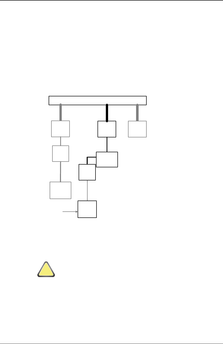
4.7 Hierarchy for Supply
Figure 8 shows a typical wiring hierarchy for the equipment power supply cabling.
Notice that the cable ratings are higher than the circuit breakers and fuse ratings. In this
example the circuit breaker rating has been de-rated to 70% of the cable maximum
continuous current rating.
Also note that the current rating of the input side of the circuit breaker from the vehicle
bus bar. This cable must be rated to exceed the current rating of the bus bar. In this case
70% de-rating has been applied.
VEHICLE BUS BAR (100A FUSED)
40A
CIRCUIT
BREAKER
CP6100
5A
CIRCUIT
BREAKER
JUNCTION
BOX
5A Rated Cable
57A RATED
CABLE
57A RATED CABLE
143A RATED
CABLE
LEGACY
EQUIPMENT
LEGACY
RELAY
ANCILLAR
Y
CIRCUIT
BREAKER
LEGACY
CIRCUIT
BREAKER
ON/OFF
CONTROL
Figure 8: Typical Bus Power Supply Circuit Breaker and Cable Rating
4.8 Hot Plugging
WARNING:
It is strongly recommended that power is turned off before the power is plugged in or out.
!
Attention
VIX Products Security Level 3 CP6100 User Manual
VXP-00261 Vix Confidential © Vix 2016
Revision 4.0 / 1 Sep 2016
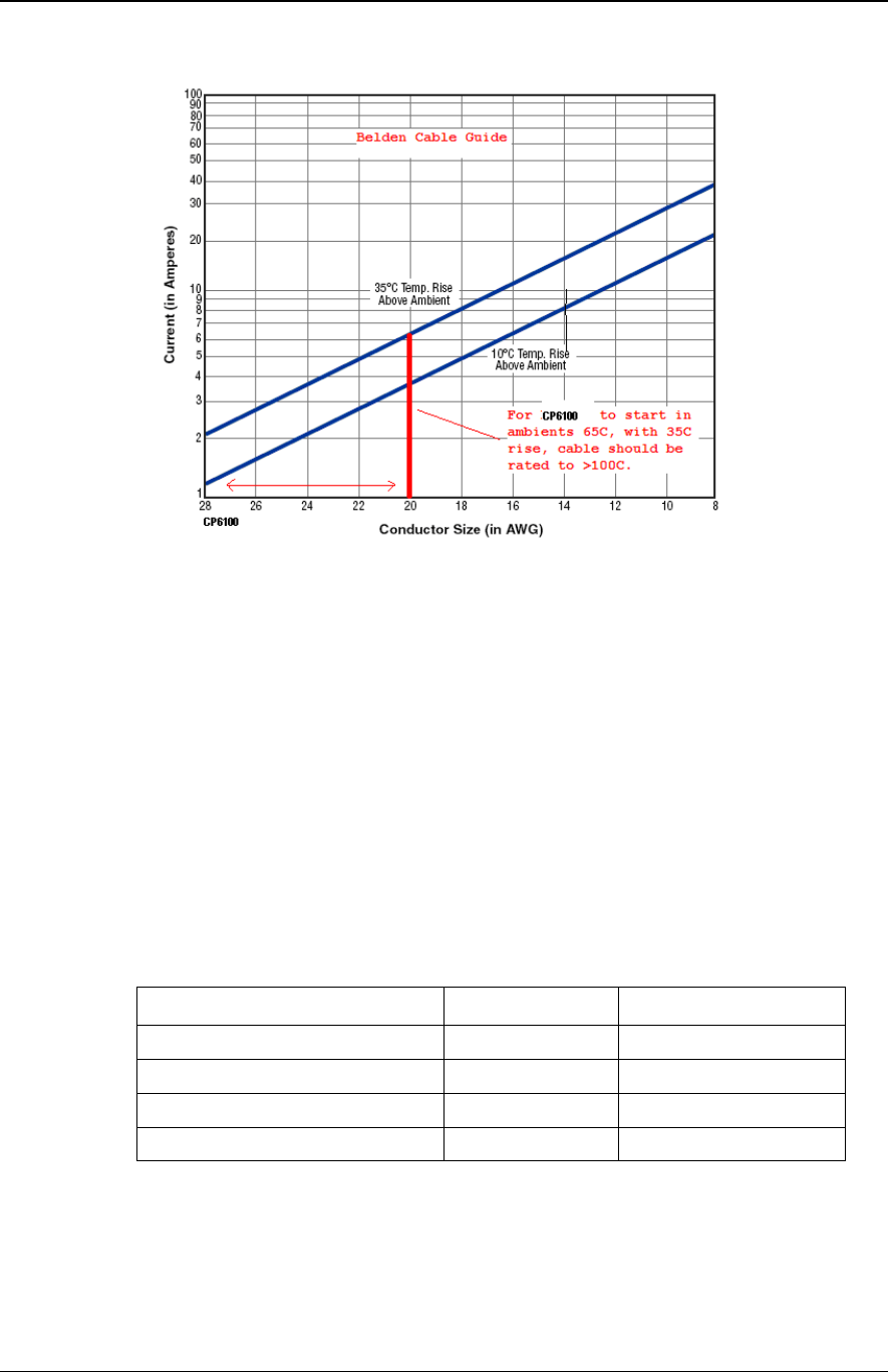
4.9 Cable Recommendations
Figure 9: Cable current handling table
For power distribution it is also critical that the cable is selected to minimise voltage drop,
especially during start up peak currents. It is recommended that the cable voltage drop
uses a peak current of 3A and a full voltage drop of <1V (including return) to select the
cable.
4.10 Length Versus Cable Size
All cables have resistance. When comparing cables of the same type and style, then
generally, the thicker the copper the lower the resistance for the same length.
If cables are to be used over long lengths then it may be necessary to increase the cable
size to reduce the voltage drop caused by the resistance of the wire and the load current.
For the CP6100 wiring the following is provided as a guide to maintain an acceptable
voltage drop.
Table 6: CP6100 Cable Size and Length Guide
Distance from Star Point Cable Size Equivalent Cable
0m-10m 20 AWG Belden 9408
10m-20m 18 AWG Belden 9409
20m-30m 16 AWG Belden 9410
30m-50m 14 AWG Belden 9411
4.11 Ground Terminations
Notice In Figure 7: Installation Wiring Diagram the star point for the power supply grounds
(negative terminals) of the transit system units. They share a common termination point
thus providing a controlled system ground reference point.

VIX Products Security Level 3 CP6100 User Manual
VXP-00261 Vix Confidential © Vix 2016
Revision 4.0 / 1 Sep 2016
4.12 Ground Termination checks
The ground connection resistances of all installed transit system units should be
measured to ensure good conductivity.
Connection should be referenced to the Transit System Ground Star Point. The
resistance from any negative power connection to the star point should be less than 0.5Ω.
4.13 Cable Specifications
VIX Products recommends using the following cables for CP6100 installation. Local and
statutory regulations should be followed for fire proofness and cable material content (i.e.
RoHS), which may override these recommendations.
Table 7: Cable Specification
Cable
Function
Cable Description Manufacturer Part No. Data
POWER to power
connector.
See Note:
2 x 16AWG 1.5mm2 Pair Low
smoke Halogen free
Belden
Power/Relay/Cont
rol /Door Switch
20 AWG Stranded
Belden 9920
Ethernet Cat5e 24AWG Un-Shielded
RS232 Serial
Chassis Earth Braid 0.75mm2
Note: Follow table 5 for cable rating versus distance.
4.13.1 Cable Extension Recommendations
The Ethernet cable can be extended if required to reach switches, hubs and gate
controllers as required. It is highly recommended that the maximum extension length is
not exceeded, as it may result in problematic operation.
Table 8: Cable Recommendations
Function Cable Description Manufacturer Part No.
Max L
Ethernet Ethernet extension Off-the-shelf NA 30m
RS232 Diagnostic extension Off-the-shelf NA 5m
USB USB Host extension Off-the-shelf NA 2m
RS422 / RS485
/ RS232 Multiprotocol extension Off-the-shelf NA 100m /
1km / 5m
VIX Products Security Level 3 CP6100 User Manual
VXP-00261 Vix Confidential © Vix 2016
Revision 4.0 / 1 Sep 2016
5 Physical characteristics
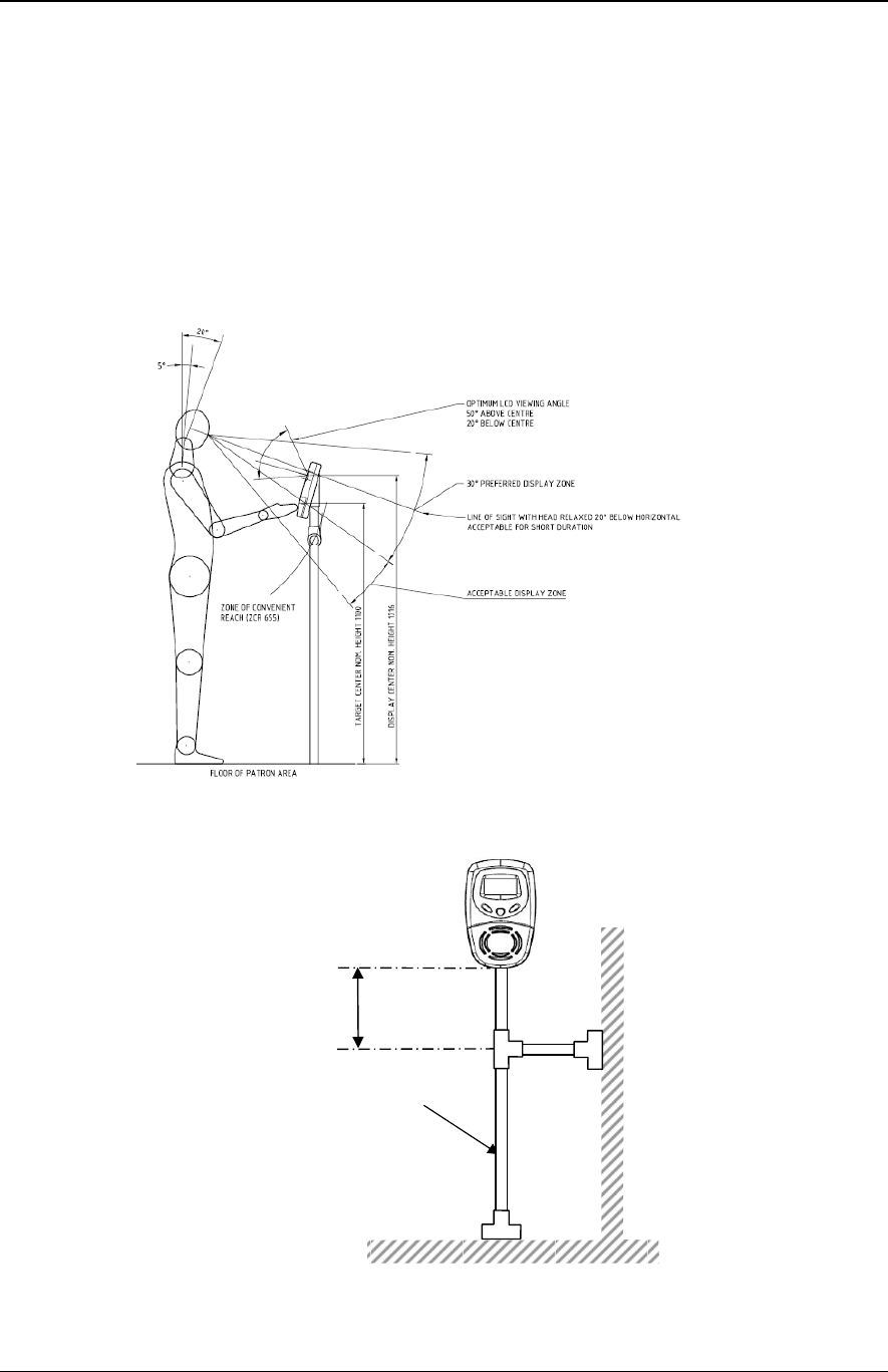
5.1 CP6100 Positioning
When positioning a CP6100 cradle within a vehicle cabin the following items should be
used as a guideline:
• Metal objects are to be located greater than 200 mm from target area to prevent
antenna de-tuning & card range reduction.
• The CP6100 should be located within easy reach of Patrons as shown in Figure
10: CP6100 positioning.
Figure 10: CP6100 positioning - height
Figure 11: CP6100 Preferred Pole Mounting Bracing
MAX. 100mm
38mm Min. Pole Dia
(1.6mm Min Wall Thickness)
OR
32mm Min. Pole Dia
(1.2mm Min Wall Thickness)
VIX Products Security Level 3 CP6100 User Manual
VXP-00261 Vix Confidential © Vix 2016
Revision 4.0 / 1 Sep 2016
6 Environmental Characteristics
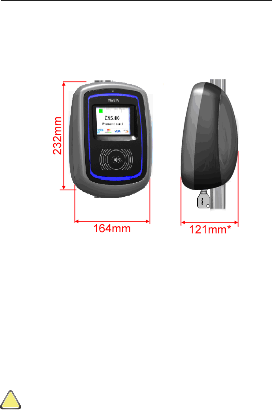
6.1 Dimensions and Weight
Units physical dimension 164mm(w) x x 232mm(h) x 121mm(d) – Including Cradle
Weight = 1 kg. Without Cradle
Figure 12 : Mechanical Dimensions
6.2 General
The casing shall have no corners, sharp edges, or exposed fixings (nuts/bolts) that may
present a hazard to the driver.
The casing shall provide unit resistance to most solvents and general-purpose cleaners.
6.3 Cradle
The cradle plates are manufactured from 304 Stainless Steel and anodised aluminium.
The plates have no corners or sharp edges that may present a hazard operators or
installers.
6.4 Cradle Mounting Instructions
The CP6100 is hard mounted to bus structure via the cradle, which are shipped as part of
the PROD0059 pole mounting kit.
The unit connectors present a low risk of accidental short circuit or electric shock when
the unit is removed, it is always recommended that power is disconnected.
!
Attention

VIX Products Security Level 3 CP6100 User Manual
VXP-00261 Vix Confidential © Vix 2016
Revision 4.0 / 1 Sep 2016
Table 9 : PROD0059 Bill of Materials
Part
Description
Supplier
Manufacturer
Manufacturer Part
LCK0012 LCK ASSY,EXTD SHFT,VISE SOUTHCO
FASTENERS
PTY LTD SOUTHCO E3-99-3694
LCK0013 KEY,FEMALE ROUND,FOR SOUTHCO
VICE ACTION LOCK SOUTHCO SOUTHCO E3-99-622-15
MF0184 MF,BKT,CRADLE MOUNT,S/S,
MF0185 MF,POLE CLAMP,
MTRL0040 MTRL,TAPE,CLOSED CELL, INDUSTRIAL
RUBBER WA TESA 60203 3.2MMX40MM
NUT0025 NUT,M5,HEX,NYLOC,SS,A2 COVENTRY
FASTENERS
WA BOSSARD BN637 M5
PKG0042 PKG,BOX,CARDBOARD,CP6100 TONTEC INT'L
LIMITED TONTEC
PKG0043 PACKAGING,BAG,MAGIC-SEAL Bunzl Limited
(Cospak) COSPAK 9/7561(150 X 225M)
PM0098 PM,CRADLE COVER,CP6100
PM0098.A ASSY,CFG,PM,CRADLE COVER
PM0102 PM,SPACER,VARIABLE POLE,
RIV0004 RIVET,4.8X10.8(X9.5),SS, COVENTRY
FASTENERS
WA BOSSARD BN 3313 4.8x10.8
SCW0032 SCW,M4X8,BTN,SKT,S/S 304 FJ SWEETMAN BOSSARD BN1593 M4X8
SCW0032 SCW,M4X8,BTN,SKT,S/S 304 PORTER
AGENCIES PTY
LTD Porter SSBHAS408
SCW0032 SCW,M4X8,BTN,SKT,S/S 304 COVENTRY BOSSARD BN1593 M4X8
SCW0090 SCW,M5x45,CSK,SKT,S/S,A2 COVENTRY
FASTENERS
WA BOSSARD BN 616 M5x45
WSH0038 WSH,M4,SPR,HLX,LCK,SS PORTER
AGENCIES PTY
LTD PORTER A SSLW4
VIX Products Security Level 3 CP6100 User Manual
VXP-00261 Vix Confidential © Vix 2016 Page 22 of 26
Revision 2.0
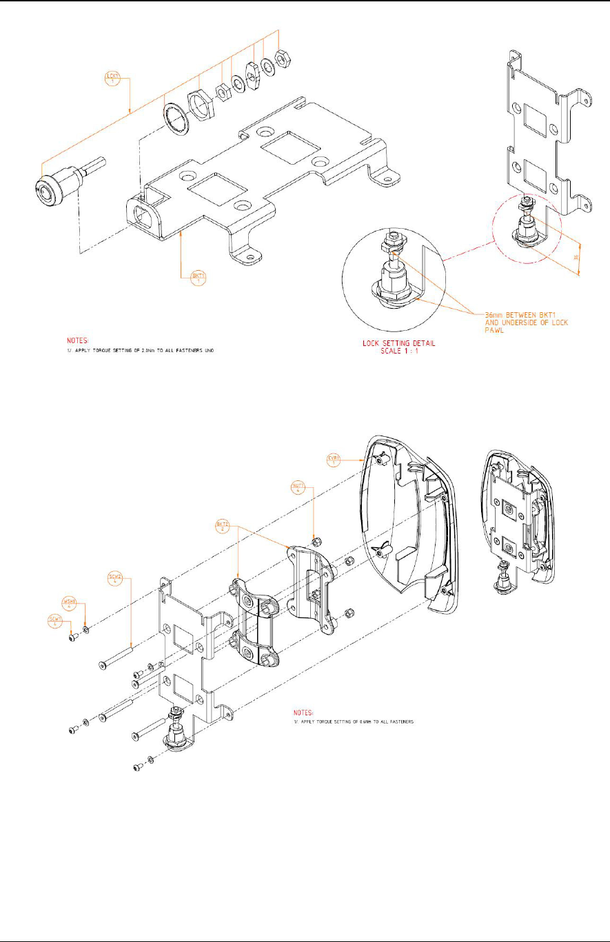
Figure 13: PROD0059 Cradle Assembly (45-0710) Page 1
Figure 14: PROD0059 Cradle Assembly (45-0710) Page 2
VIX Products Security Level 3 CP6100 User Manual
VXP-00261 Vix Confidential © Vix 2016 Page 23 of 26
Revision 2.0
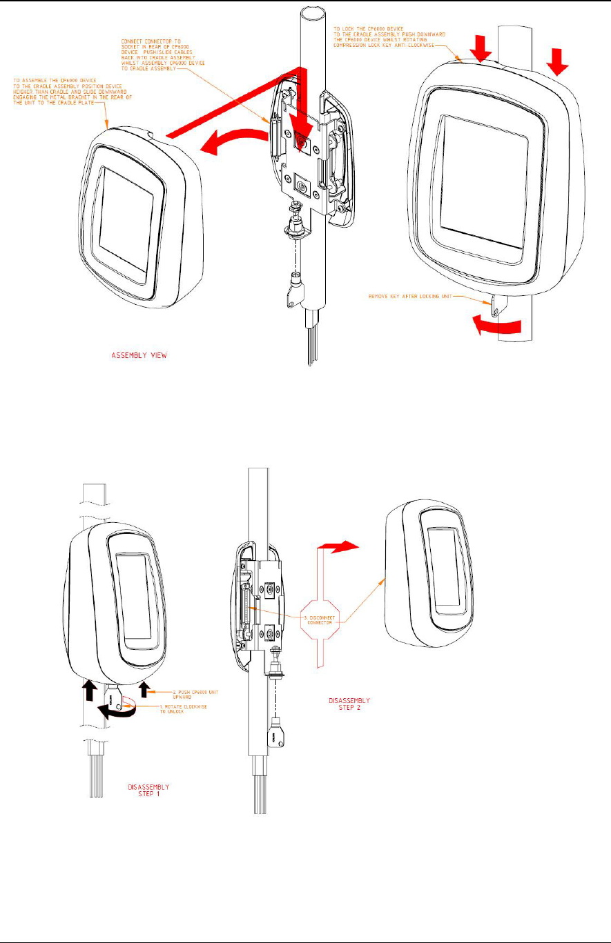
7 Installation Guidelines for the Cradle
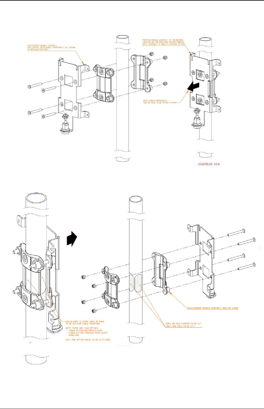
Figure 15: Installation Instructions (57-0073) Page 1
Figure 16: Installation Instructions (57-0073) Page 2
VIX Products Security Level 3 CP6100 User Manual
VXP-00261 Vix Confidential © Vix 2016 Page 24 of 26
Revision 2.0
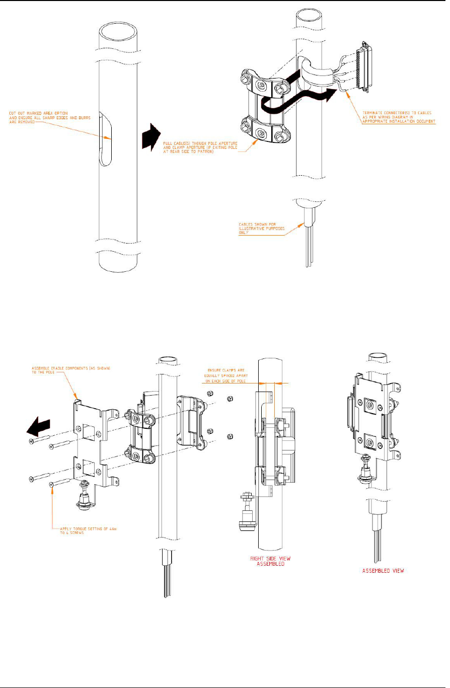
Figure 17: Installation Instructions (57-0073) Page 3
Figure 18: Installation Instructions (57-0073) Page 5
VIX Products Security Level 3 CP6100 User Manual
VXP-00261 Vix Confidential © Vix 2016 Page 25 of 26
Revision 2.0
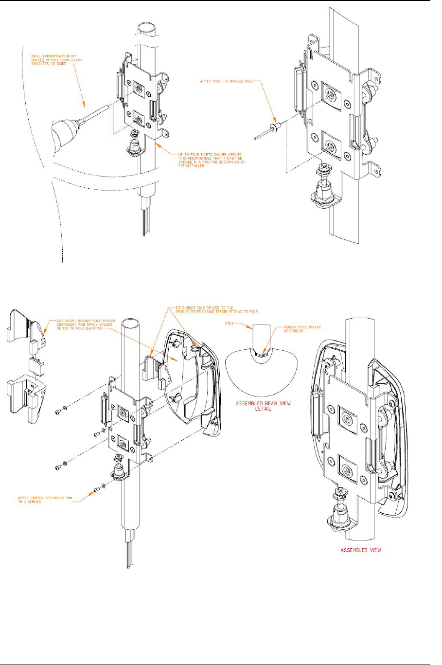
Figure 19: Installation Instructions (57-0073) Page 6
Figure 20: Installation Instructions (57-0073) Page 7
VIX Products Security Level 3 CP6100 User Manual
VXP-00261 Vix Confidential © Vix 2016 Page 26 of 26
Revision 2.0
Figure 21: Installation Instructions (57-0073) Page 8
Figure 22: Installation Instructions (57-0073) Page 9
Note: Regard references to CP6000 as CP6100, where DB37 is show, this is to be considered
as replaced by the four new Molex Mini-Fit Jr connectors.