Vix Technology PCP6100 CP6100 card processor on-board validator User Manual PCP6100
Vix Technology (Aust) Pty Ltd CP6100 card processor on-board validator PCP6100
UserManual.wiki
>
Vix Technology
>
PCP6100 User Manual
User Manuel
Navigation menu
Upload a User Manual
Namespaces
Wiki Guide
HTML
PDF
Info
Views
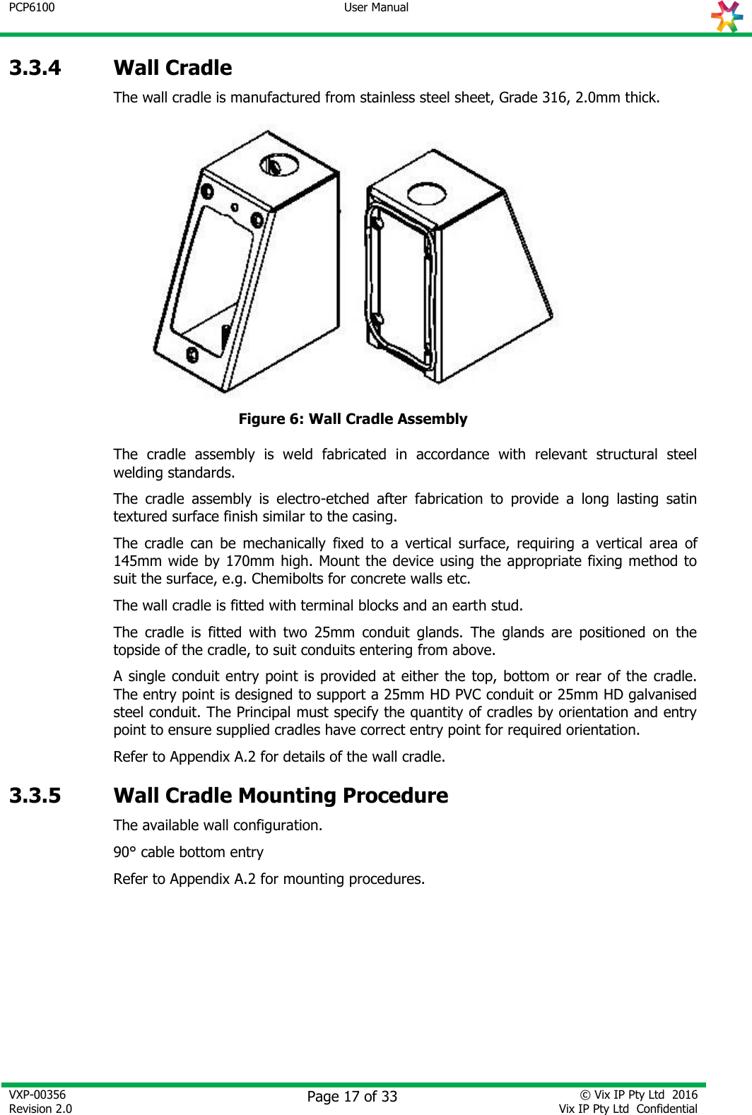
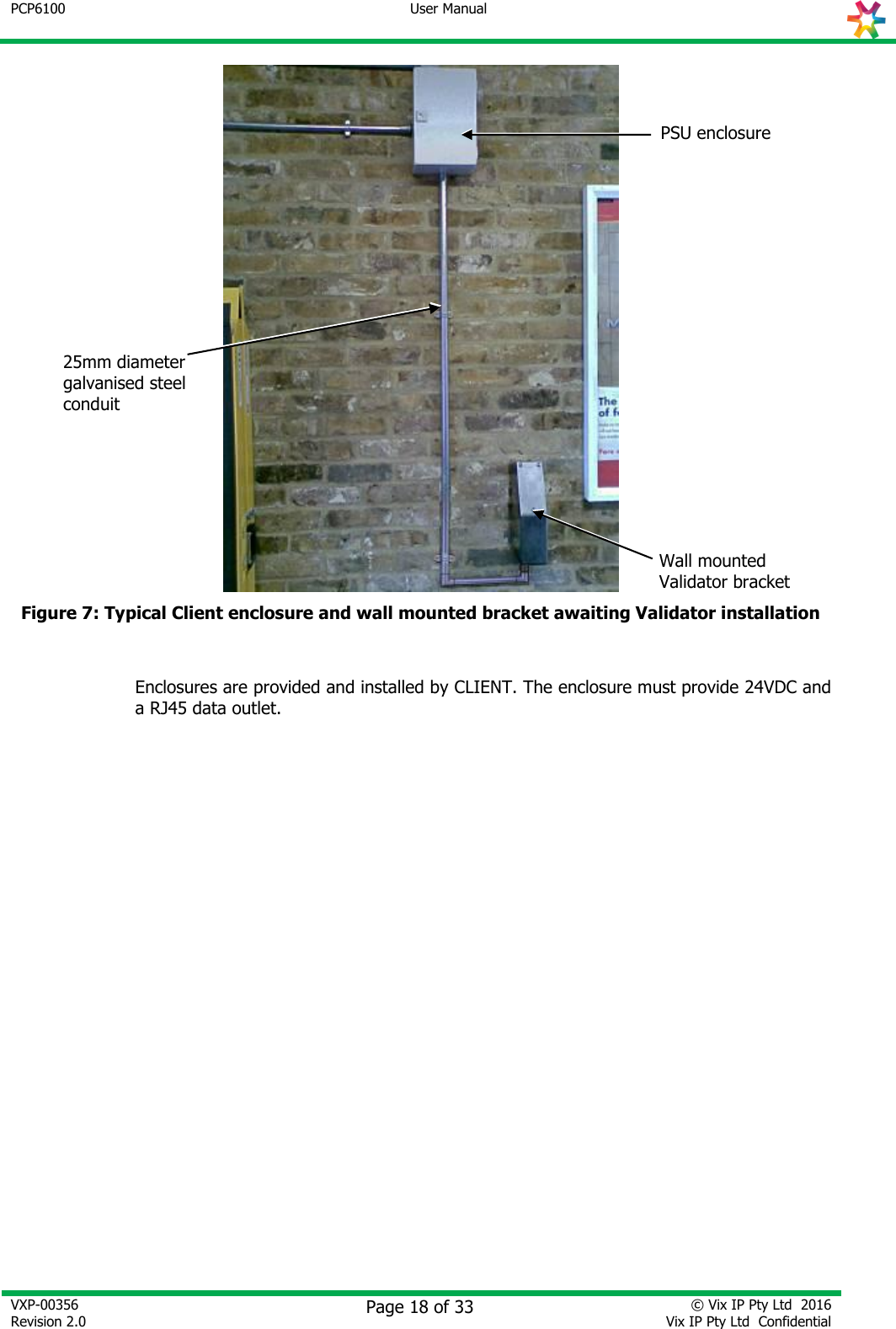
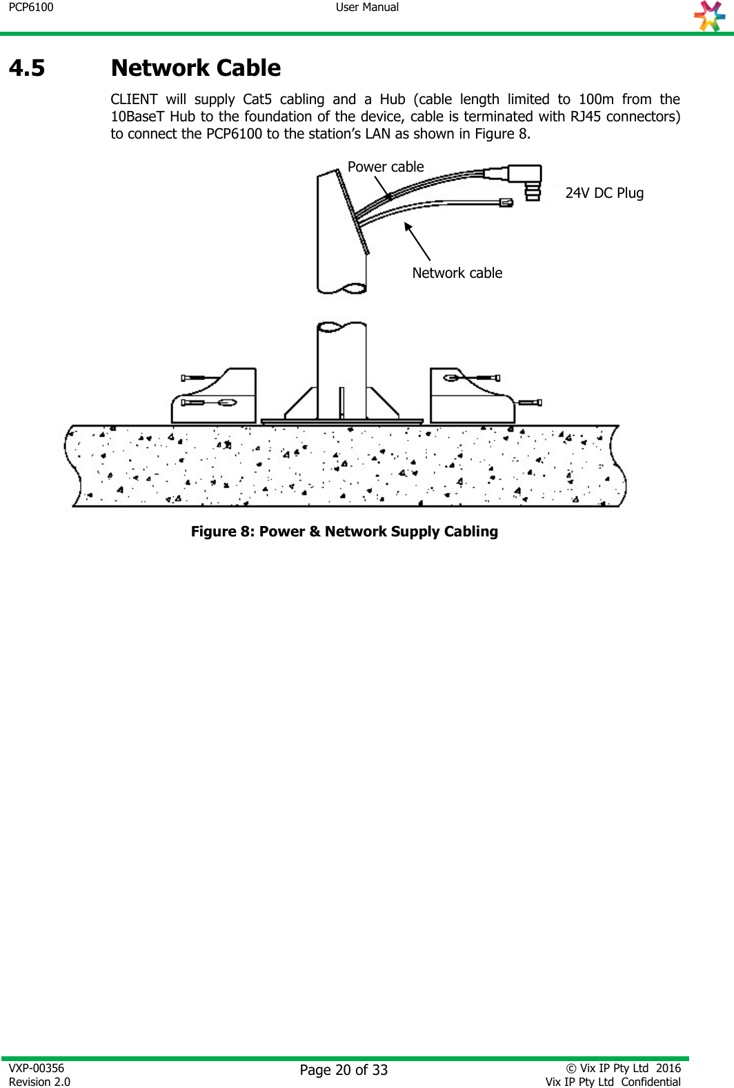
User Manual
Discussion / Help
Navigation