Vix Technology PCP6100 CP6100 card processor on-board validator User Manual PCP6100
Vix Technology (Aust) Pty Ltd CP6100 card processor on-board validator PCP6100
User Manuel

PCP6100
USER MANUAL
Document No.
Revision
Revision Date
VXP-00356
2.0
26 May 2016

The information contained in this document is copyright and may not be
reproduced, stored in a retrieval system or transmitted in any form or by
any means in whole or in part without the express written consent of Vix
IP Pty Ltd.
This material is also confidential and may not be disclosed in whole or
part to any third party nor used in any manner whatsoever other than for
a purpose expressly consented to by Vix IP Pty Ltd in writing.

PCP6100
User Manual
VXP-00356
Revision 2.0
Page 3 of 33
© Vix IP Pty Ltd 2016
Vix IP Pty Ltd Confidential
Document History
Revision
Revision
Date
Description
Author
.1
19 May 2013
Initial Draft
Chris Bailye
.2
24/05/2013
Updated Power Supply to 24VDC device
Chris Bailye
.3
24/05/2013
Updated the data ports
Chris Bailye
1.0
26/05/2016
Updated to include FCC compliance statement
Gino Bertino
2.0
6/09/2016
Added FCC warning and RF exposure statement.
Gino Bertino

PCP6100
User Manual
VXP-00356
Revision 2.0
Page 4 of 33
© Vix IP Pty Ltd 2016
Vix IP Pty Ltd Confidential
Table of Contents
1 INTRODUCTION ............................................................................................................................ 6
1.1 PURPOSE ......................................................................................................................................... 6
1.2 SCOPE ............................................................................................................................................ 6
1.3 WHO SHOULD READ THIS MANUAL ........................................................................................................ 6
1.4 TERMINOLOGY .................................................................................................................................. 7
1.5 SAFETY ........................................................................................................................................... 7
1.5.1
Safety Precautions .................................................................................................................. 7
1.5.2
Warnings and Cautions ........................................................................................................... 8
1.5.3
EMC and Safety Standards Applied ........................................................................................... 8
1.5.3.1
FCC compliance statement ................................................................................................................ 9
1.5.3.2
Human exposure statement: ............................................................................................................. 9
2 OVERVIEW .................................................................................................................................. 10
2.1 INSTALLATION COMPONENT LIST ......................................................................................................... 11
2.2 INSTALLATION PROCESS .................................................................................................................... 12
3 MOUNTING DESIGN .................................................................................................................... 13
3.1 PCP6100 MOUNTING ....................................................................................................................... 13
3.2 TOOLS .......................................................................................................................................... 13
3.3 POSITIONING .................................................................................................................................. 14
3.3.1
General Mounting Procedure .................................................................................................. 15
3.3.2
Mounting Pole ....................................................................................................................... 15
3.3.3
Pole Mounting Procedure ....................................................................................................... 15
3.3.4
Wall Cradle ........................................................................................................................... 17
3.3.5
Wall Cradle Mounting Procedure ............................................................................................ 17
4 CABLE INSTALLATION ................................................................................................................ 19
4.1 PROCEDURE .................................................................................................................................... 19
4.2 TOOLS .......................................................................................................................................... 19
4.3 POWER SUPPLY CABLING ................................................................................................................... 19
4.4 POWER CABLE PIN-OUT .................................................................................................................... 19
4.5 NETWORK CABLE ............................................................................................................................. 20
4.6 NETWORK CABLE ASSEMBLY ............................................................................................................... 21
4.7 NETWORK CABLE PIN-OUT ................................................................................................................. 21
5 PCP6100 TERMINATION ............................................................................................................. 22
5.1 DATA PORTS .................................................................................................................................. 22
6 PCP6100 INSTALLATION ............................................................................................................ 23
6.1 TOOLS .......................................................................................................................................... 23
6.2 MOUNTING PCP6100 BASE PLATE ....................................................................................................... 23
6.3 LOCKING PCP6100 .......................................................................................................................... 23
7 CHANGING SAM .......................................................................................................................... 24
8 PCP6100 SOFTWARE INSTALLATION ......................................................................................... 25
8.1 REQUIRED EQUIPMENT ...................................................................................................................... 25
8.2 PROCEDURE .................................................................................................................................... 25
APPENDIX A ATTACHMENTS .......................................................................................................... 26
A.1 INSTALLATION GUIDES FOR POLE MOUNTED PCP6100 ............................................................................. 26
A.1.1
Single Head Pole Mounted PCP6100 ....................................................................................... 27
A.1.2
Pole Mounting Details ............................................................................................................ 28
A.1.3
Installation Pole Electrical ...................................................................................................... 29
A.2 INSTALLATION GUIDES FOR WALL CRADLED PCP6100 .............................................................................. 30

PCP6100
User Manual
VXP-00356
Revision 2.0
Page 5 of 33
© Vix IP Pty Ltd 2016
Vix IP Pty Ltd Confidential
A.2.1
Wall Mount Bracket 90° ......................................................................................................... 31
A.3 SPECIAL INSTALLATION TOOLS ............................................................................................................ 32
APPENDIX B EXTERNAL CONNECTOR DESCRIPTIONS .................................................................. 33
B.1 24VDC POWER ................................................................................................................................ 33
B.2 100BASET NETWORK ....................................................................................................................... 33
B.3 AUXILIARY COMMUNICATIONS ............................................................................................................. 33
List of Tables
TABLE 1: TERMINOLOGY .................................................................................................................................... 7
TABLE 2: COMPONENTS REQUIRED TO INSTALL THE PCP6100 VALIDATOR .................................................................... 11
TABLE 3: DC POWER ...................................................................................................................................... 33
TABLE 4: NETWORK LAN ................................................................................................................................. 33
List of Figures
FIGURE 1: PCP6100 VALIDATOR ......................................................................................................................... 6
FIGURE 2: PCP6100 VALIDATOR MOUNTED ON SUPPORT POLE .................................................................................. 14
FIGURE 3: PCP6100 MOUNTING POLE. ................................................................................................................ 15
FIGURE 4: 250MM PCD ................................................................................................................................... 16
FIGURE 5: BASE COVER .................................................................................................................................... 16
FIGURE 6: WALL CRADLE ASSEMBLY .................................................................................................................... 17
FIGURE 7: TYPICAL CLIENT ENCLOSURE AND WALL MOUNTED BRACKET AWAITING VALIDATOR INSTALLATION.......................... 18
FIGURE 8: POWER & NETWORK SUPPLY CABLING ................................................................................................... 20
FIGURE 9: POWER CABLE AND NETWORK CABLE AT THE POLE, READY TO BE CONNECTED TO THE VALIDATOR .......................... 21
FIGURE 10: PCP6100 POWER AND NETWORK CONNECTIONS .................................................................................... 22
FIGURE 11: LOCK COVER FITTED ........................................................................................................................ 23
FIGURE 12: LOCATION OF SAM SLOTS. ................................................................................................................ 24
PCP6100
User Manual
VXP-00356
Revision 2.0
Page 6 of 33
© Vix IP Pty Ltd 2016
Vix IP Pty Ltd Confidential
1 Introduction
This installation guide provides the instructions for installing and setting up a PCP6100
also known as the PCP5700.EMV. From here on in, this document will refer to the unit
simply as the PCP6100.
1.1 Purpose
The purpose of this document is to provide general installation guidelines for the
PCP6100 Validator. It includes instructions for mechanical installation, cabling, testing,
and configuration procedures.
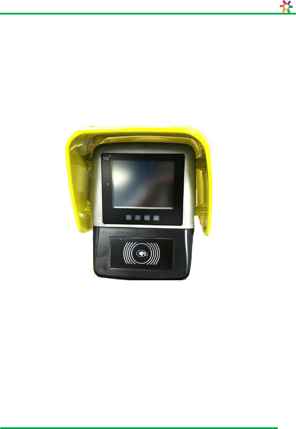
Figure 1 shows the PCP6100 Validator.
Figure 1: PCP6100 Validator
1.2 Scope
The scope of the document is limited to describing the installation guidelines for the
PCP6100 only. This manual is to be used by Supervisors and Technicians performing on
site installations.
1.3 Who Should Read This Manual
This document is intended for use by technicians installing PCP6100 Validator units, such
as:
Installation personnel
Work on mounting, commissioning and removal, primarily of the operational
apparatus systems.

PCP6100
User Manual
VXP-00356
Revision 2.0
Page 7 of 33
© Vix IP Pty Ltd 2016
Vix IP Pty Ltd Confidential
1.4 Terminology
The following table contains a list of common acronyms/terms and their meanings.
Table 1: Terminology
Term
Definition
AFC
Automatic Fare Collection
AS
Australian Standard
BoM
Bill of Materials
CF
Compact Flash memory card
DC
Direct Current
DHCP
Dynamic Host Configuration Protocol
HBOM
Hardware Bill Of Materials
HD
Hot Dipped (galvanising)
LAN
Local Area Network
LCD
Liquid Crystal Display
OD
Outside Diameter
OS
Operating System
PC
Personal Computer (desktop or compatible)
PCD
Pitch Circle Diameter
PCP6100
Validator
PVC
Poly Vinyl Chloride
RS232
Serial Communications Standard
SBOM
Software Bill Of Materials
SP
Service Pack (of an operating system)
SSH
Secure Shell network protocol
UD
Usage Data
WXP
Windows XP operating system (desktop edition)
1.5 Safety
All installation work must be carried out in accordance with relevant Safety Codes and
Codes of Practice as well as recognized industry standards. The appropriate protective
clothing must be worn where necessary. Tools must be used in accordance with
manufacturers’ instructions and suitable for the task.
Personnel attempting to perform any work on the electrical wiring must be trained and
suitably qualified in the appropriate electrical codes of practice and must work in
accordance with those codes.
1.5.1 Safety Precautions
This document presents important information that is intended to ensure the safe and
effective use of this device. Please read this information carefully, and store it in an
accessible location near your installation.
PCP6100
User Manual
VXP-00356
Revision 2.0
Page 8 of 33
© Vix IP Pty Ltd 2016
Vix IP Pty Ltd Confidential
1.5.2 Warnings and Cautions
Warnings and cautions are used to call attention to potential hazards. Failure to observe
the information provided with the warnings and cautions may result in injury or property
damage. Be sure that you understand the meaning of each before you proceed.
WARNING:
Indicates a potentially lethal hazard. Failure to observe a WARNING may
result in severe injury or death.
CAUTION:
Failure to observe a CAUTION may result in personal injury or damage to
the device or other property.
WARNING:
The device should only be installed, serviced and maintained by qualified service
personnel. Improper repair work can be dangerous. Tampering with this device
may result in injury, fire, or electric shock.
In accordance with local requirements, the device should only be installed by a
qualified electrician. Improper work can be dangerous. Tampering with this device
may result in injury, fire or electric shock.
Disconnect all power before carrying out repairs or service.
Be sure to use the specified power source for the device. Connection to an
improper power source may cause fire or electric shock.
CAUTION:
This device must be earthed (grounded).
The enclosure section of this device is heavy caution needs to be used when
opening the device to avoid damage or injury.
1.5.3 EMC and Safety Standards Applied
Product Name: PCP6100
The following standards have been applied to this device:
CE Marking
Safety: EN60950-1:2002
FCC Part 15

PCP6100
User Manual
VXP-00356
Revision 2.0
Page 9 of 33
© Vix IP Pty Ltd 2016
Vix IP Pty Ltd Confidential
1.5.3.1 FCC compliance statement
This equipment has been tested and found to comply with the limits for a Class B digital
device, pursuant to Part 15 of the FCC Rules. These limits are designed to provide
reasonable protection against harmful interference in a residential installation. This
equipment generates, uses and can radiate radio frequency energy and, if not installed
and used in accordance with the instructions, may cause harmful interference to radio
communications. However, there is no guarantee that interference will not occur in a
particular installation. If this equipment does cause harmful interference to radio or
television reception, which can be determined by turning the equipment off and on, the
user is encourage to try to correct the interference by one or more of the following
measures:
Reorient or relocate the receiving antenna
Increase the separation between the equipment and receiver
Connect the equipment into an outlet on a circuit different from that to which the
receiver is connected
Consult the dealer or an experienced radio/TV technician for help
WARNING:
THE GRANTEE IS NOT RESPONSIBLE FOR ANY CHANGES OR MODIFICATIONS NOT
EXPRESSLY APPROVED BY THE PARTY RESPONSIBLE FOR COMPLIANCE. SUCH
MODIFICATIONS COULD VOID THE USER’S AUTHORITY TO OPERATE THE EQUIPMENT.
1.5.3.2 Human exposure statement:
To meet human exposure requirements a separation distance of > 20cm should be
maintained.

PCP6100
User Manual
VXP-00356
Revision 2.0
Page 10 of 33
© Vix IP Pty Ltd 2016
Vix IP Pty Ltd Confidential
2 Overview
This document details the process for installing the PCP6100 Validator.
The PCP6100 Validator can be installed in either of two configurations, pole mounted or
wall mounted.
PCP6100
User Manual
VXP-00356
Revision 2.0
Page 11 of 33
© Vix IP Pty Ltd 2016
Vix IP Pty Ltd Confidential
2.1 Installation Component List
Before proceeding with installation, check that the BoM and the equipment is to the latest
applicable revision.
The components shown in Table 2 are required to install the PCP6100 Validator.
Table 2: Components required to install the PCP6100 Validator
Item
Quantity
Reference
Pole
mounted
Wall
mounted
PCP-6100 Validator
assembly
1
1
PCP6100 Item No.
PCP6100 AEAA
PCP5000 Install Kit
1
1
ASS0085
M8 Cap Head Bolts
3
3
M8 Spring Washer
3
3
M8 Flat Washer
3
3
Mounting Gasket
1
1
Pole Mount Assembly
1
POLE PCP6100 Item No.
PROP0036
Power Supply Assembly
1
Base Cover (2 parts)
1
M6 Tamperproof Button
Head Screws for base
cover
4
Pole Mounting Gasket
1
Loctite for use with base
cover screws
1
Wall Mount Assembly
1
CRADLE WALL BRACKET
90 BOT ENT PCP6100
Item No. PROD0038
Power Supply assembly
1
Wall Mounting Gasket
1
Silicone for mounting
bracket to wall
1
Chemical Resin Studs
M16 dia x 125 deep
for fixing pole to floor or
bracket to wall
4
4
Pre installed by VIX
TECHNOLOGY/CLIENT
Shielded Network
Cable
1
1
Pre installed by Client
Power Supply/Cable
1
1
Pre installed by Client

PCP6100
User Manual
VXP-00356
Revision 2.0
Page 12 of 33
© Vix IP Pty Ltd 2016
Vix IP Pty Ltd Confidential
2.2 Installation Process
The installation procedure is:
1) Install the pole on a level concrete pad or install the wall mounting bracket on a suitable
vertical masonry or concrete wall, with appropriate access for cables.
2) Fit the sealing gasket to the pole or wall mounting bracket.
Apply silicone to the rear of the wall mounting bracket to seal the bracket to the
wall.
3) Connect the power and Ethernet cables to the rear of the Validator.
4) Fit the Validator and mounting bracket (door) to the pole or bracket and secure with
three M8 bolts.
5) Close the Validator onto the mounting bracket (door), close the lock and remove
the key.
6) Fit and secure the lock cover using tamperproof screws.

PCP6100
User Manual
VXP-00356
Revision 2.0
Page 13 of 33
© Vix IP Pty Ltd 2016
Vix IP Pty Ltd Confidential
3 Mounting Design
The following sections describe the mounting design for the PCP6100.
3.1 PCP6100 Mounting
The following section provides a step-by-step installation procedure for mounting a pole
cradle for a PCP6100
The following PCP6100 variants are designed and supplied:
Support stand to affix to floor – for one PCP6100
The design of the stand is documented in Appendix A.
Stands and wall brackets are installed in a manner that any standard design fixings are
concealed and access to them is not available to the public.
3.2 Tools
Installation personnel should have a variety of tools available to cope with the different
types of installation situations that may be encountered. Depending on station access,
mounting surface construction, available power outlets, blocking of public thoroughfares
for installation etc. Include items such as, safety barriers, warning signs and marking
tape, safety vest etc.
The following tools are required to mount a PCP6100:
Ratchet handle with ¼” drive or adaptor
1/4” drive universal joint
¼” drive 100mm long extension
5mm hexagonal ball drive
¼” drive socket to suit wall bolts/nuts
13mm ¼” drive deep socket (optional)
M6 tamperproof screwdriver for base cover
M16 ring spanner.
M16 socket with ratchet handle and ½” drive.
Power drill 10mm chuck.
Hilti TE 40-AVR rotary hammer drill or similar for drilling 18mm holes in concrete
Masonry drills, 18mm and others
Extension lead
RCD outlet
Battery operated drill with adjustable clutch settings
Selection of screwdriver bits and sockets to fit battery drill.
230V isolating transformer
Torque wrench
PCP6100
User Manual
VXP-00356
Revision 2.0
Page 14 of 33
© Vix IP Pty Ltd 2016
Vix IP Pty Ltd Confidential
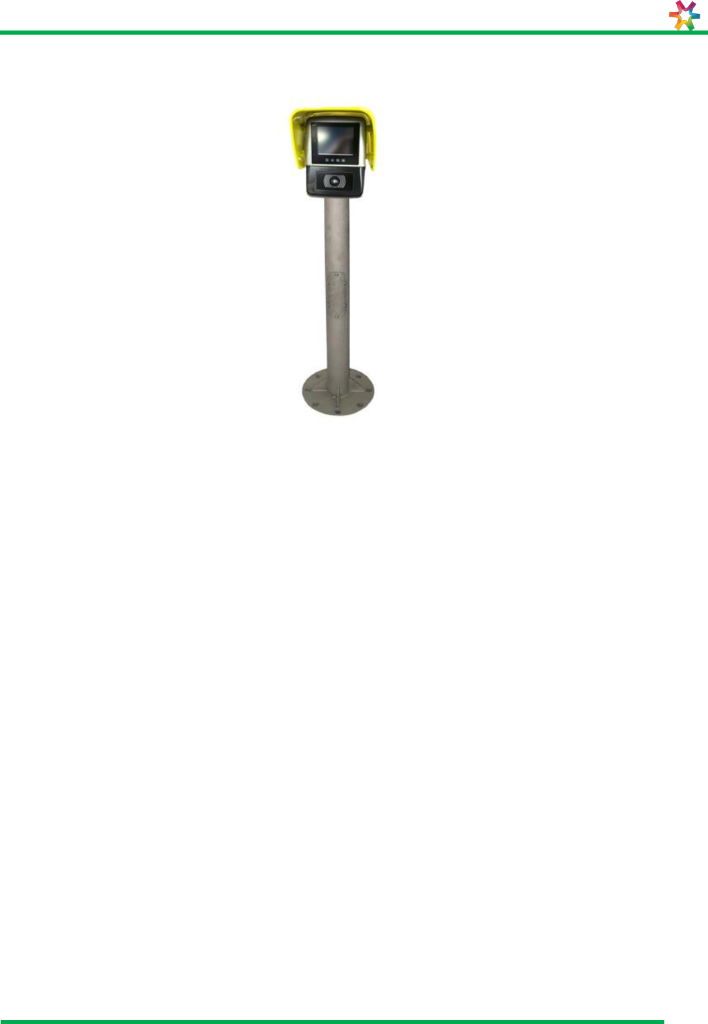
Figure 2 shows a PCP6100 Validator mounted on its support stand.
Figure 2: PCP6100 Validator mounted on support pole
3.3 Positioning
The following sections describe how the PCP6100 Validator is to be mounted and
positioned.
Note:
Install the PCP6100 in a location and orientation that minimises direct sun penetration
onto the LCD display in order to avoid screen glare and overheating.
PCP6100
User Manual
VXP-00356
Revision 2.0
Page 15 of 33
© Vix IP Pty Ltd 2016
Vix IP Pty Ltd Confidential
3.3.1 General Mounting Procedure
3.3.2 Mounting Pole
Figure 3: PCP6100 mounting pole.
The mounting pole is manufactured from stainless steel tube O.D.90mm, Grade 316, wall
thickness 2.7mm.
The pole arrangement is weld fabricated in accordance with relevant structural steel
welding standards.
The pole is electro-etched after fabrication to provide a long lasting satin textured surface
finish similar to the casing.
The pole is mechanically fixed to the station platform by four fasteners.
The pole includes a round flat base with eight mounting holes to facilitate the mounting
of the PCP6100 at 45º increments.
A stainless steel base cover, finished in a long lasting satin textured surface, encloses the
base plate.
The base cover hides the mounting fasteners.
The pole is fitted with terminal blocks and a ground stud. Refer to Appendix A.1
3.3.3 Pole Mounting Procedure
The pole is mounted on a suitable concrete substrate.
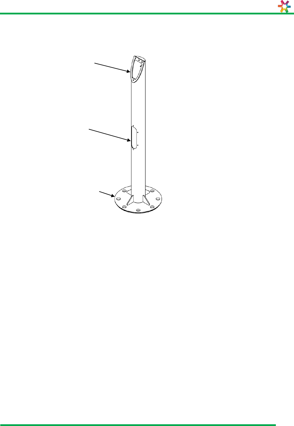
4 x 18mm holes are drilled to a depth of 130mm equally spaced on 250mm PCD
as shown in Figure 4.
PCP6100 Validator
mounting plate
Cable access port
Floor mounting plate

PCP6100
User Manual
VXP-00356
Revision 2.0
Page 16 of 33
© Vix IP Pty Ltd 2016
Vix IP Pty Ltd Confidential
Figure 4: 250mm PCD
Install chemical resin studs of M16 set 125mm deep into the concrete. For
procedures on the use of chemibolts refer to the manufacturer’s instructions
supplied with the bolts.
Cable access to the PCP6100 Validator is through the concrete base and the
mounting pole.
Following installation of the pole, a base cover is installed to hide the floor fixing
bolts. Apply “Loctite” to the 4 x M6 x 35 tamperproof button head screws shown in
Figure 5.
Figure 5: Base cover
Tamperproof button head screws

PCP6100
User Manual
VXP-00356
Revision 2.0
Page 17 of 33
© Vix IP Pty Ltd 2016
Vix IP Pty Ltd Confidential
3.3.4 Wall Cradle
The wall cradle is manufactured from stainless steel sheet, Grade 316, 2.0mm thick.
Figure 6: Wall Cradle Assembly
The cradle assembly is weld fabricated in accordance with relevant structural steel
welding standards.
The cradle assembly is electro-etched after fabrication to provide a long lasting satin
textured surface finish similar to the casing.
The cradle can be mechanically fixed to a vertical surface, requiring a vertical area of
145mm wide by 170mm high. Mount the device using the appropriate fixing method to
suit the surface, e.g. Chemibolts for concrete walls etc.
The wall cradle is fitted with terminal blocks and an earth stud.
The cradle is fitted with two 25mm conduit glands. The glands are positioned on the
topside of the cradle, to suit conduits entering from above.
A single conduit entry point is provided at either the top, bottom or rear of the cradle.
The entry point is designed to support a 25mm HD PVC conduit or 25mm HD galvanised
steel conduit. The Principal must specify the quantity of cradles by orientation and entry
point to ensure supplied cradles have correct entry point for required orientation.
Refer to Appendix A.2 for details of the wall cradle.
3.3.5 Wall Cradle Mounting Procedure
The available wall configuration.
90° cable bottom entry
Refer to Appendix A.2 for mounting procedures.

PCP6100
User Manual
VXP-00356
Revision 2.0
Page 18 of 33
© Vix IP Pty Ltd 2016
Vix IP Pty Ltd Confidential
Figure 7: Typical Client enclosure and wall mounted bracket awaiting Validator installation
Enclosures are provided and installed by CLIENT. The enclosure must provide 24VDC and
a RJ45 data outlet.
Wall mounted
Validator bracket
PSU enclosure
25mm diameter
galvanised steel
conduit

PCP6100
User Manual
VXP-00356
Revision 2.0
Page 19 of 33
© Vix IP Pty Ltd 2016
Vix IP Pty Ltd Confidential
4 Cable Installation
This section provides a step-by-step installation procedure for routing cables to the
PCP6100 mounting pole or bracket.
WARNING:
Disconnect the mains power before you start any work. Ensure appropriate over current
and earth fault protection are provided in the mains supply.
The PCP6100 needs to be supplied with 24VDC.
4.1 Procedure
Floor Mounted Pole Assembly:
1) Prior to the PCP6100 being fitted to the mounting pole, a 24VDC power cable and
a shielded RJ45 cable need to be inserted from the bottom of the pole, out through
the top.
2) Client may install a suitably certified 24VDC power supply in the pole of the pole
mounted device. This power supply, must be provided, installed and tested by the
CLIENT.
Wall Mounted Bracket Assembly:
1) Prior to the PCP6100 being fitted to the mounting bracket, a 24VDC power cable
and a shielded RJ45 cable need to be inserted from the bottom of the bracket, out
through the top.
2) Client may install a suitably certified 24VDC power supply in a CLIENT provided
enclosure. This power supply, must be provided, installed and tested by the
CLIENT.
4.2 Tools
The following tools are required to terminate a PCP6100:
Flat head screw driver
Wire Cutter/Stripper
RJ45 Crimping Tool
4.3 Power Supply Cabling
The PCP6100 operates from a nominal 24V DC Power Supply.
The PCP6100’s operating voltage is 16V DC to 36V DC nominal. The under-voltage
detect voltage is 15V DC nominal. The over-voltage shutdown is 38V DC +/- 2V DC and
reverse polarity protection up to 400V DC
Data cabling installation and testing is carried out by CLIENT.
4.4 Power Cable Pin-Out
Refer to Appendix B.1 for Power Cable Pin-Out details.

PCP6100
User Manual
VXP-00356
Revision 2.0
Page 20 of 33
© Vix IP Pty Ltd 2016
Vix IP Pty Ltd Confidential
4.5 Network Cable
CLIENT will supply Cat5 cabling and a Hub (cable length limited to 100m from the
10BaseT Hub to the foundation of the device, cable is terminated with RJ45 connectors)
to connect the PCP6100 to the station’s LAN as shown in Figure 8.
Figure 8: Power & Network Supply Cabling
24V DC Plug
Power cable
Network cable

PCP6100
User Manual
VXP-00356
Revision 2.0
Page 21 of 33
© Vix IP Pty Ltd 2016
Vix IP Pty Ltd Confidential
Figure 9: Power cable and network cable at the pole, ready to be connected to the Validator
4.6 Network Cable Assembly
The RJ45 connector should suit 8 way CAT 5 cable used:
Shielded
Solid/Stranded
Small Core/Large Core
Round/Flat/D-shaped
4.7 Network Cable Pin-Out
Refer to Appendix B.2 for Network Cable Pin-Out details.
Shielded Ethernet cable
24v DC Plug
(4 way circular)

PCP6100
User Manual
VXP-00356
Revision 2.0
Page 22 of 33
© Vix IP Pty Ltd 2016
Vix IP Pty Ltd Confidential
5 PCP6100 Termination
Figure 10: PCP6100 Power and Network connections
Connect 24V DC plug (4 way circular) in PCP6100;
Connect RJ45 connector into Ethernet LAN port in PCP6100.
5.1 Data Ports
the PCP6100 contains 4 data ports –
External Ethernet LAN RJ45 (shown in Figure 10)
External Aux Communications RJ45 (shown in Figure 10)
Internal USB (shown in Figure 12Figure 10)
Internal Serial Port (shown in Figure 12Figure 10)
CAUTION:
Any equipment that is plugged into the External Aux Communications RJ45 port, internal
USB port or the internal serial port, must comply with clause 4.7 of EN 60950-1:2006.

PCP6100
User Manual
VXP-00356
Revision 2.0
Page 23 of 33
© Vix IP Pty Ltd 2016
Vix IP Pty Ltd Confidential
6 PCP6100 Installation
The mounting plate is fitted to the rear of the casing to provide a complete unit for easy
transport and handling.
The mounting plate is manufactured from 5mm thick stainless steel.
6.1 Tools
5mm hexagonal ball drive
6.2 Mounting PCP6100 Base Plate
The mounting base is located to the mounting fixture by one 6mm locating dowel, and
mechanically fixed using three M8 stainless steel set screw fasteners.
Torque the screw fasteners to 15Nm.
6.3 Locking PCP6100
The PCP6100 uses a lock manufactured by DOM. Refer to VIX TECHNOLOGY for lock
details.
A lock cover with sealing O-Ring is provided, to protect the lock, and to ensure the IP
rating of the unit.
W
Warning:
Ensure the PCP6100 is locked. When PCP6100 is unlocked the key is captured and
cannot be removed.
Replace lock cover ensuring O-ring is positioned correctly and using tamper resistant
fasteners.
Figure 11: Lock cover fitted
Lock cover

PCP6100
User Manual
VXP-00356
Revision 2.0
Page 24 of 33
© Vix IP Pty Ltd 2016
Vix IP Pty Ltd Confidential
7 Changing SAM
Preconfigured SAM cards need to be installed into the Validator at the locations shown
below. Installation of the card is conducted in a workshop situation prior to installing the
PCP6100 Validator.
Figure 12: Location of SAM slots.

PCP6100
User Manual
VXP-00356
Revision 2.0
Page 25 of 33
© Vix IP Pty Ltd 2016
Vix IP Pty Ltd Confidential
8 PCP6100 Software Installation
This section describes how to re-install factory software onto the PCP6100 validator.
8.1 Required Equipment
The following items are required in order to successfully complete the software
installation:
PCP6100 validator
Regulated power supply: 24 VDC, 3 A
PC with Windows XP SP2, RS232, Ethernet
Power cable from validator rear power socket to the DC regulated power
supply
Ethernet cable from validator rear network socket to PC
Serial cable from validator internal DE9 connector (on main board) to PC
Vix software package: "SW8484.02012017CR msp_lnx_cobra v1.0.zip"
8.2 Procedure
On the PC:
Set network IP address / mask to 172.18.255.254 / 255.255.0.0
Unzip the SW8484 software package to any convenient directory
Invoke the CobraLoad utility from within the unzipped package
Start up a terminal emulator such as HyperTerminal, with serial
communication settings 115200bps, 8-N-1
Power up the validator while holding down the enter key on the terminal - this should
interrupt the boot process
Observe output on the terminal stops at a U-Boot prompt
Type "run msp" (without quotes) at the prompt
Observe that the validator starts downloading software from the PC over the Ethernet
connection (moving progress bars will appear in CobraLoad, and progress will be
reported at the terminal)
Once complete, the validator will reboot and go into DAMS (Diagnostic and
Manufacturing Software)
Within DAMS, the validator will proceed automatically to soak testing (a series of non-
interactive tests)
The validator is now ready for safety testing.

PCP6100
User Manual
VXP-00356
Revision 2.0
Page 26 of 33
© Vix IP Pty Ltd 2016
Vix IP Pty Ltd Confidential
Appendix A Attachments
A.1 Installation Guides for Pole Mounted PCP6100
Pole Flanged Single Head Pole Mounted PCP5000 – Drg:35-3040
Installation Pole Mounting Details – Drg No: 50-0220
Installation Pole Electrical – Drg No: 50-0221

PCP6100
User Manual
VXP-00356
Revision 2.0
Page 27 of 33
© Vix IP Pty Ltd 2016
Vix IP Pty Ltd Confidential
A.1.1 Single Head Pole Mounted PCP6100
L:\SSW\Development\
PCP5700 Validator Install Guide\Reference Material\35-3040-B Pole POLE FLANGED.pdf

PCP6100
User Manual
VXP-00356
Revision 2.0
Page 28 of 33
© Vix IP Pty Ltd 2016
Vix IP Pty Ltd Confidential
A.1.2 Pole Mounting Details

PCP6100
User Manual
VXP-00356
Revision 2.0
Page 29 of 33
© Vix IP Pty Ltd 2016
Vix IP Pty Ltd Confidential
A.1.3 Installation Pole Electrical

PCP6100
User Manual
VXP-00356
Revision 2.0
Page 30 of 33
© Vix IP Pty Ltd 2016
Vix IP Pty Ltd Confidential
A.2 Installation Guides for Wall Cradled PCP6100
Installation Guide Wall Mount 90°- Drg No: 50-0227 Pg3
Special Installation Tools Required – Drg No: 50-0227 Pg4

PCP6100
User Manual
VXP-00356
Revision 2.0
Page 31 of 33
© Vix IP Pty Ltd 2016
Vix IP Pty Ltd Confidential
A.2.1 Wall Mount Bracket 90°

PCP6100
User Manual
VXP-00356
Revision 2.0
Page 32 of 33
© Vix IP Pty Ltd 2016
Vix IP Pty Ltd Confidential
A.3 Special Installation Tools

PCP6100
User Manual
VXP-00356
Revision 2.0
Page 33 of 33
© Vix IP Pty Ltd 2016
Vix IP Pty Ltd Confidential
Appendix B External Connector Descriptions
Details of connector pin outs are shown below.
B.1 24Vdc Power
Table 3: DC Power
Pin
Circular Door Connector
1
+24Vdc
2
+24Vdc
3
GND
4
GND
B.2 100BaseT Network
Table 4: Network LAN
Pin
RJ45 Door Connector
1
TXD+
2
TXD-
3
RXD+
4
5
6
RXD-
7
8
B.3 Auxiliary Communications
Table 5: Auxiliary Communications and 1-Wire
Pin
RJ45 Door Connector
1
RS-232 Tx
2
RS-232 Rx
3
RS-232 GND
4
RS-485 -
5
RS-485 +
6
RS-485 GND
7
1-Wire I/O
8
1-Wire GND