Von Duprin 6300 105530
User Manual: Von Duprin 6300 Installation Instructions
Open the PDF directly: View PDF ![]() .
.
Page Count: 2
*P516-961*
P516-961
Surface Mounted Rim Strike
6300
Installation Instructions
Important:
Installations of the RIM strike qualify as “Indoor Use Only” when
not continuously exposed to an outdoor environment. Ensure
the exit device functions as intended for life safety concerns by
verifying electric strike and exit device compatibility. Maximum latch
projection is essential to obtaining full holding force.
When installed in a fail secure manner, the local authority having
jurisdiction shall be consulted with regard to the use of selected
panic hardware to ensure emergency exit from the secured area.
Catalog specications
Model
6300
6300
Mode
Fail Secure
Fail Secure
Voltage
12V
24V
Current
DC
DC
Duty
Continuous
Continuous
Amps
0.50
0.24
Ohms
22
89
FSE = Fail Locked / Fail Secure
DC = Direct Current
Continuous Duty = Energized 1 minute or more
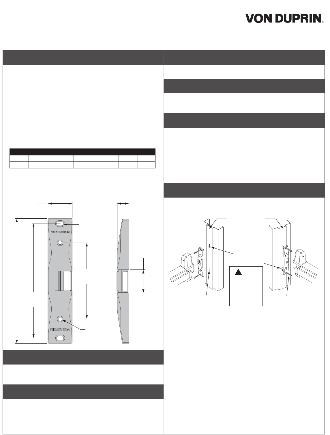
Dimensional Details
1³⁄₄"
(44.5mm)
5¹⁄₂"
(139.7mm)
8¹⁄₄"
(209.6mm)
Lockdown
holes
Horizontal
adjustment
mounting holes
³⁄₄"
(19.0mm)
1⁵⁄₈"
(42.0mm)
9"
(228.6mm)
1 Find center line
Determine the horizontal center line of the exit device latch and
transfer center line to the frame stop
2 Center-punch mounting holes
Position the paper template onto the frame aligning with center line
and against the closed door. Center-punch the two mounting holes
and the wire access hole as shown
3 Drill and tap
Drill and tap the two mounting holes and drill the wire access hole
4 Test t
Test t electric strike to ensure full latch engagement. Add provided
spacer if required
5 Wire connections
Make wire connections from the power source to the appropriate
wire harness supplied. Use the 12V harness for 12VDC. Use the
24V harness only for 24VDC
LNote: Overheated or burnt coils caused by incorrect
voltage/wire harness combinations will not be covered
under warranty
6 Mount electric strike
Using the Z\v-20 UNC screws provided, loosely mount the electric
strike using the horizontal mounting holes (outer slots)
Wire access
hole location
is relative to
the exit device
orientation.
!NOTE:
Mounting
Screw
(2 places)
¹⁄₄-20 UNC
(2 places)
³⁄₄" (19mm)
Wire access hole
Door Frame Stop
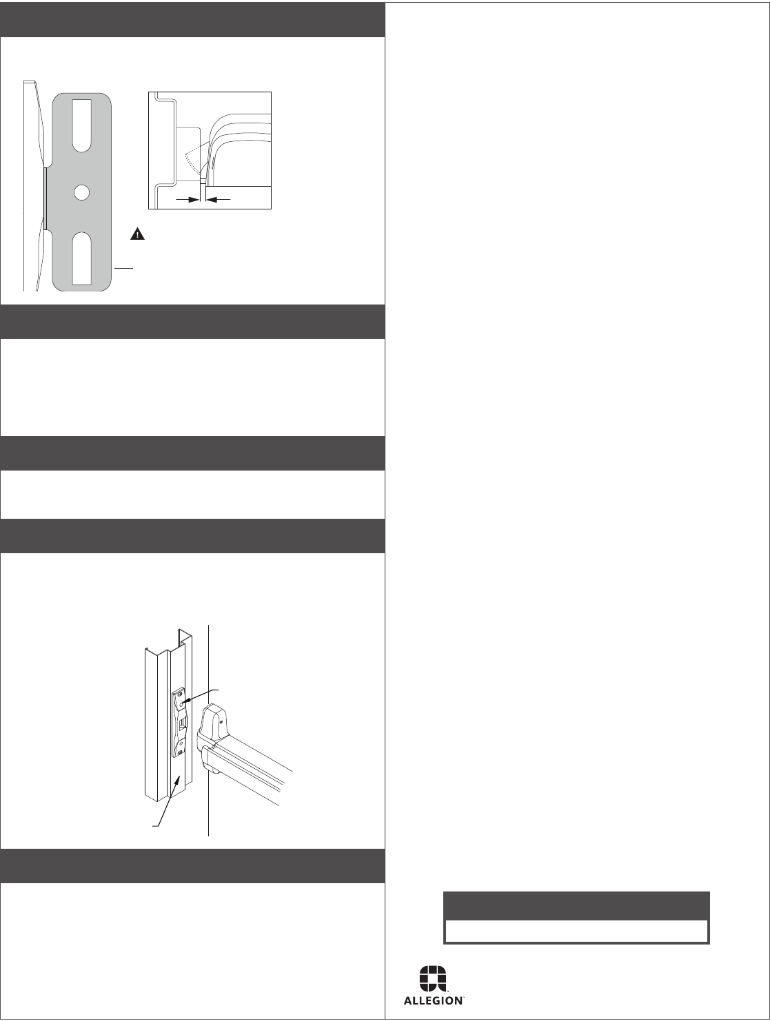
7 Install Exit Device
Install exit device per manufacturer instructions and align plastic
template as shown
99 Rim
template shown
³⁄₁₆"
WARNING: For proper operation,
a ³⁄₁₆" gap (minimum) is required.
8 Adjust strike
Adjust the electric strike horizontally until exit device latch fully
engages with the door closed
LNote: Ensure a Z\zn" (1.5mm) clearance between exit device
latch and electric strike is maintained. Latchbolt should
not touch the keeper
9 Check screws and operation
Tighten the two mounting screws and check operation. Adjust the
horizontal position of the electric strike as required
10 Prepare holes
Using the electric strike as a template, prepare the two locking
holes by drilling and tapping for Z\v-20 UNC screws. Using the Z\v-20
UNC screws provided, secure the electric strike through the locking
holes
Door Frame
Locking Screw
(2 places)
11 Check Proper Electrical and Mechanical Function
Customer Service
1-877-671-7011 www.allegion.com/us
© Allegion 2014
P516-961 Rev. 07/14-a
