Von Duprin 911373 F 98/99 Rim Installation Instructions 107600
User Manual: Von Duprin 98/99 Rim Installation Instructions Installation Instructions
Open the PDF directly: View PDF ![]() .
.
Page Count: 8
911373-00
© Allegion 2014
Printed in U.S.A.
911373-00 Rev. 05/14-f
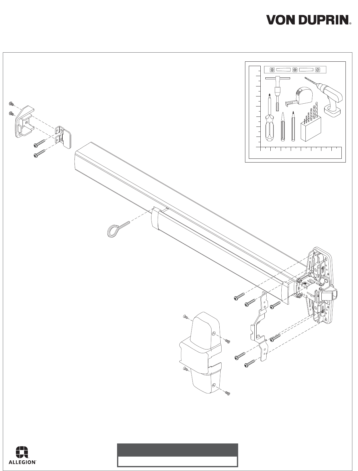
#10-24
Dogging Key
(use to lock down pushbar)
Rim Exit Device Installation Instructions
98/99
Customer Service
1-877-671-7011 www.allegion.com/us
2
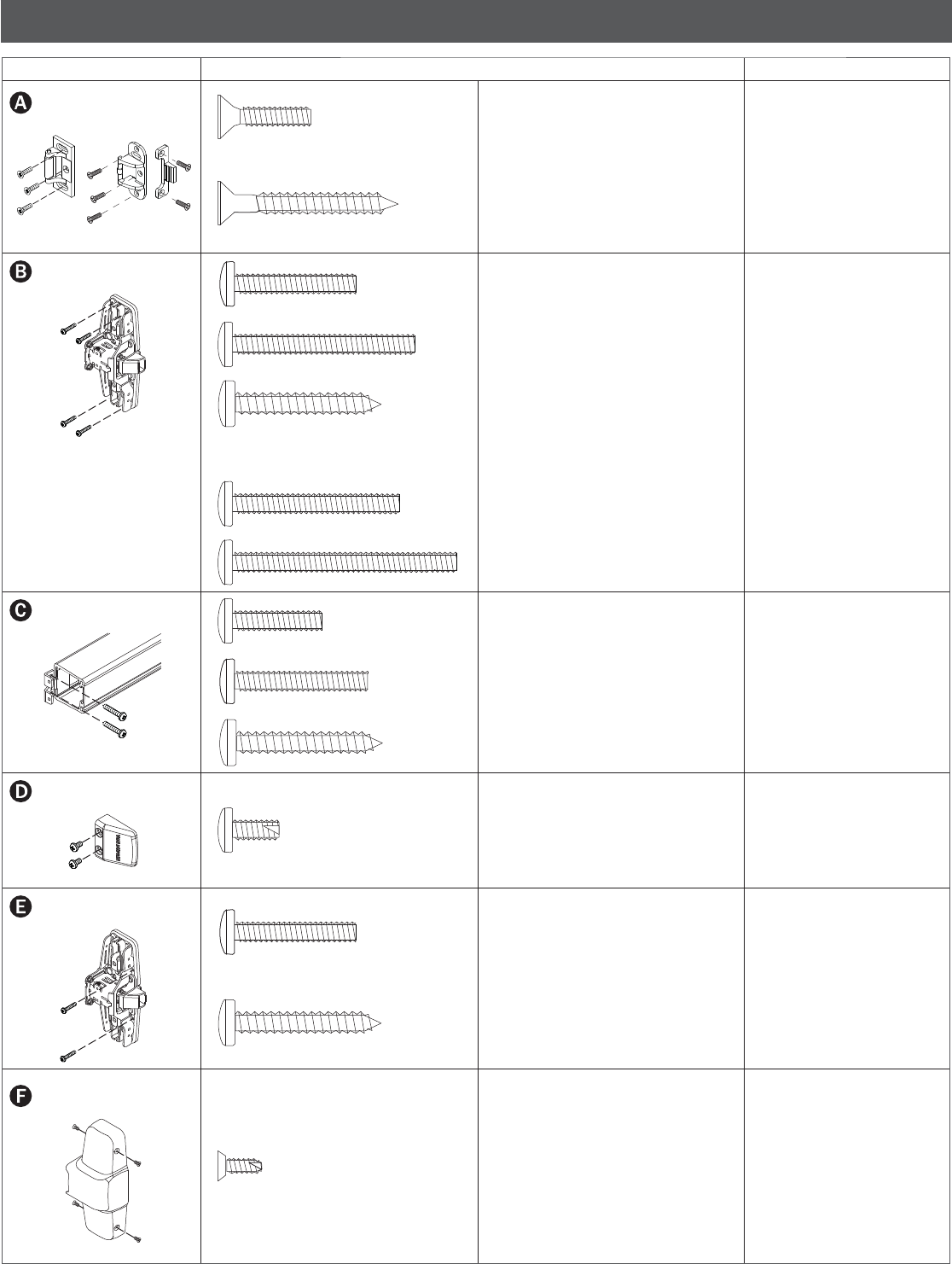
SCREW CHART
Device Subassembly Screw Application
499F Strike299 Strike
#10-24 x ³⁄₄” (19 mm) Metal frame
#10 x 1¹⁄₂” (38 mm) Wood screw Wood frame
#10-24 x 1” (25 mm) Surface mount or Sex bolts
1³⁄₄” (44 mm) door
#10-24 x 1¹⁄₂” (38 mm) Sex bolts, 2¹⁄₄” (57 mm) door
#10 x 1¹⁄₄” (32 mm) Wood screw Surface mount (wood)
Packaged with 990 Trims:
#10-24 x 1³⁄₈” (35 mm) 1³⁄₄” (44 mm) door, 990 Trim
#10-24 x 1⁷⁄₈” (48 mm) 2¹⁄₄” (57 mm) door, 990 Trim
#10-24 x ³⁄₄” (19 mm) Surface mount or Sex bolts
1³⁄₄” (44 mm) door
#10-24 x 1¹⁄₈” (29 mm) Sex bolts, 2¹⁄₄” (57 mm) door
#10 x 1¹⁄₄” (32 mm) Wood screw Surface mount (wood)
#10-16 x ³⁄₈” (10 mm) Thread cutting End cap
#10-24 x 1” (25 mm) Surface mount (metal)
#10 x 1¹⁄₄” (32 mm) Wood screw Surface mount (wood)
#8-18 x ³⁄₈” (10 mm) Thread cutting Center case cover
3
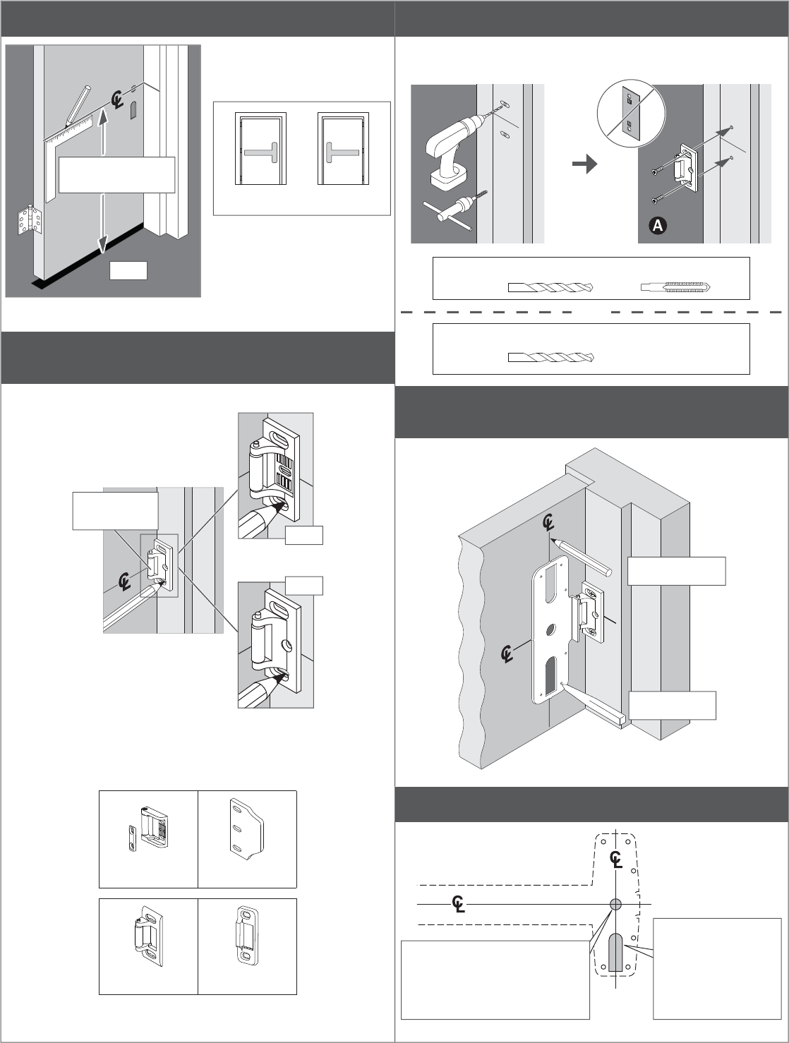
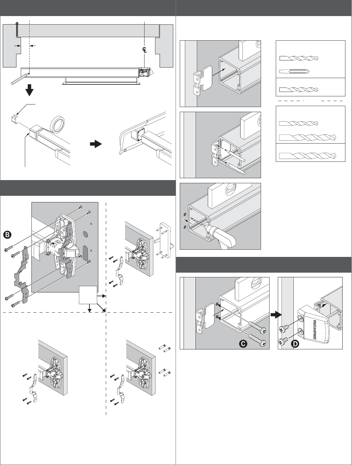
1 Draw horizontal device and strike center lines (C
L).
For double doors with a
mullion and strike already
installed, use existing
strike center line.
RHR LHR
RHR
* 39¹³⁄₁₆” (101.1 cm)
from fi nished fl oor
*
2 Align strike on C
L and mark the two slotted
holes.
Q For 499F strike installation, see page 6.
299
OR
Roller
(against door)
299F
Q For more information on the strikes shown below, go to
http://w3securitytechnologies.com and look for the
Support area for Von Duprin installation instructions.
1439 1609
264 1606
3 Prepare 2 holes and install 2 screws.
Q See “Screw Chart” on previous page for screw types and
sizes
Metal #25 #10-24
OR
Wood
¹⁄₈” (3 mm) x 1” (25 mm) deep
4 Position template against strike and on C
L and
mark door.
Mark Vertical C
L
Mark 6 holes
5 If necessary, prepare cutouts for cylinder and trim.
RHR shown, LHR opposite
For outside cylinder applications:
Mark with template and cut out
Metal door (cut device side)
Wood door (cut thru)
For trim applications
with working lever,
thumbpiece, or knob:
Mark with template
and cut out (cut
device side only)
4
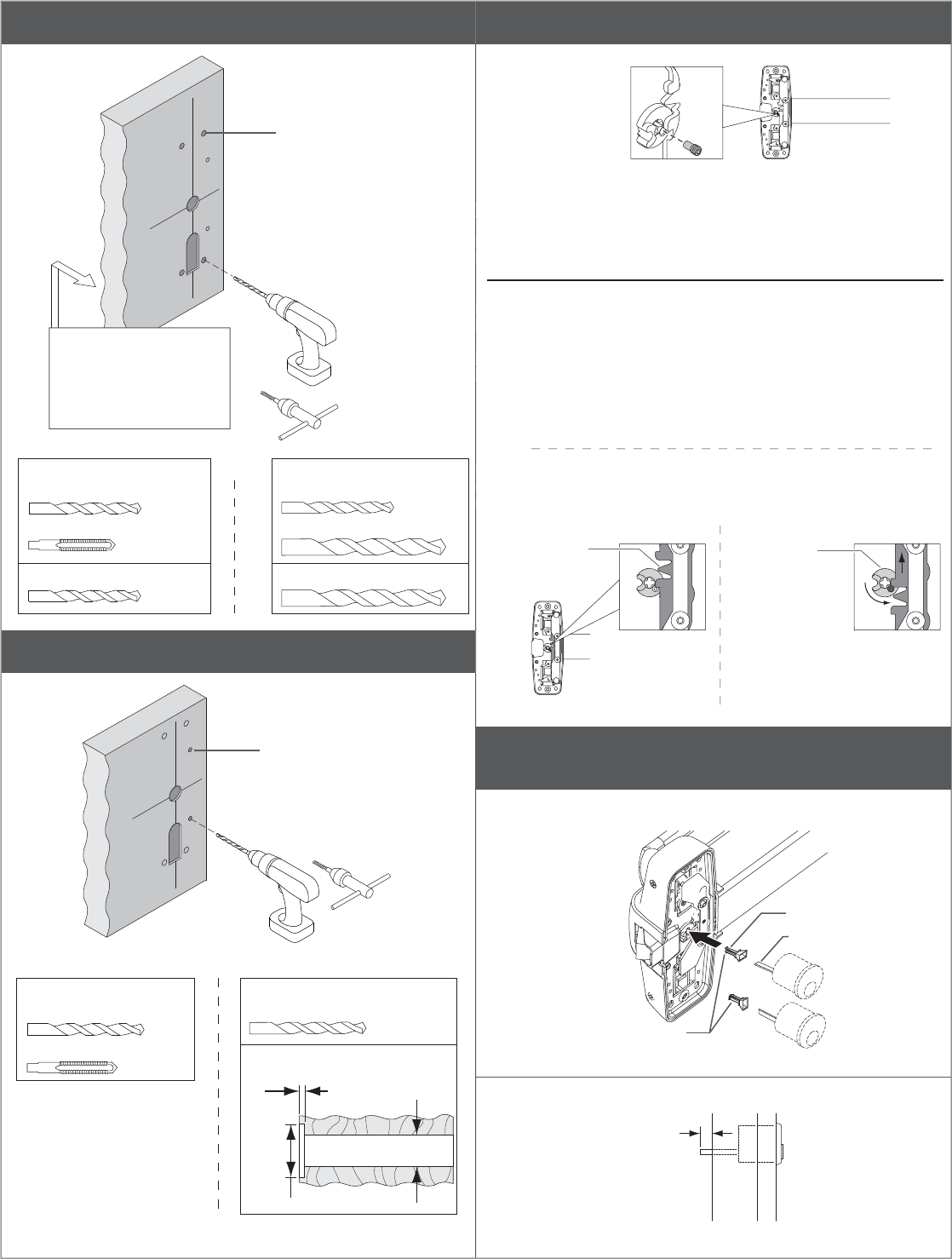
6 Prepare 4 center case mounting holes.
See trim instructions
for pull side door
preparation. Line X-X in
trim instructions is same
as vertical device C
L.
Four mounting holes
#25
#10-24
WOOD METAL
WOOD METAL
¹⁄₈” (3 mm) x 1” (25 mm) Deep ¹³⁄₃₂” (10 mm) Drill Thru
SEX BOLTS or 990 TRIMS
¹⁄₄” (6 mm) Device Side
¹³⁄₃₂” (10 mm) Trim Side
OR
SURFACE MOUNT
7 Prepare 2 center case support holes.
Two support holes
#25
#10-24
METAL
¹⁄₈” (3 mm) x 1” (25 mm) Deep
¹⁄₁₆” (2 mm)
⁵⁄₁₆” (16 mm)
Exterior
³⁄₈”
(10 mm)
98/99
98/99-F
#825 Sex bolts (2) required
98/99 and 98/99-F
OR WOOD
8 If necessary, remove NL drive screw
With the NL drive screw removed, key locks and unlocks lever, knob, or
thumb piece. For the trims listed below, REMOVE NL drive screw.
996L 696TP 990TP
996K 697TP
With the NL drive screw installed, key retracts latch bolt. DO NOT remove
NL drive screw for the following applications:
NL, EO, DT trims and 98/99-2 double cylinder devices (i.e. TP-2,
L-2, and K-2).
If the trim being installed is "BE" (i.e. 996L-BE), the trim lock tumbler
on the back of the device must be in the UP position before device
is installed. This allows the trim to be unlocked at all times.
*
*996L-BE
*996K-BE
*E996L
*E996L-BE
*696TP-BE
*697TP-BE
*990TP-BE
NL drive screw
Factory installed on
back of center case
Correct
Orientation
(RHR shown)
Incorrect
Orientation
trim lock
tumbler in
UP position
If necessary,
remove drive
screw and
rotate cam
until trim lock
tumbler is in
UP position,
then reinstall
drive screw
360˚
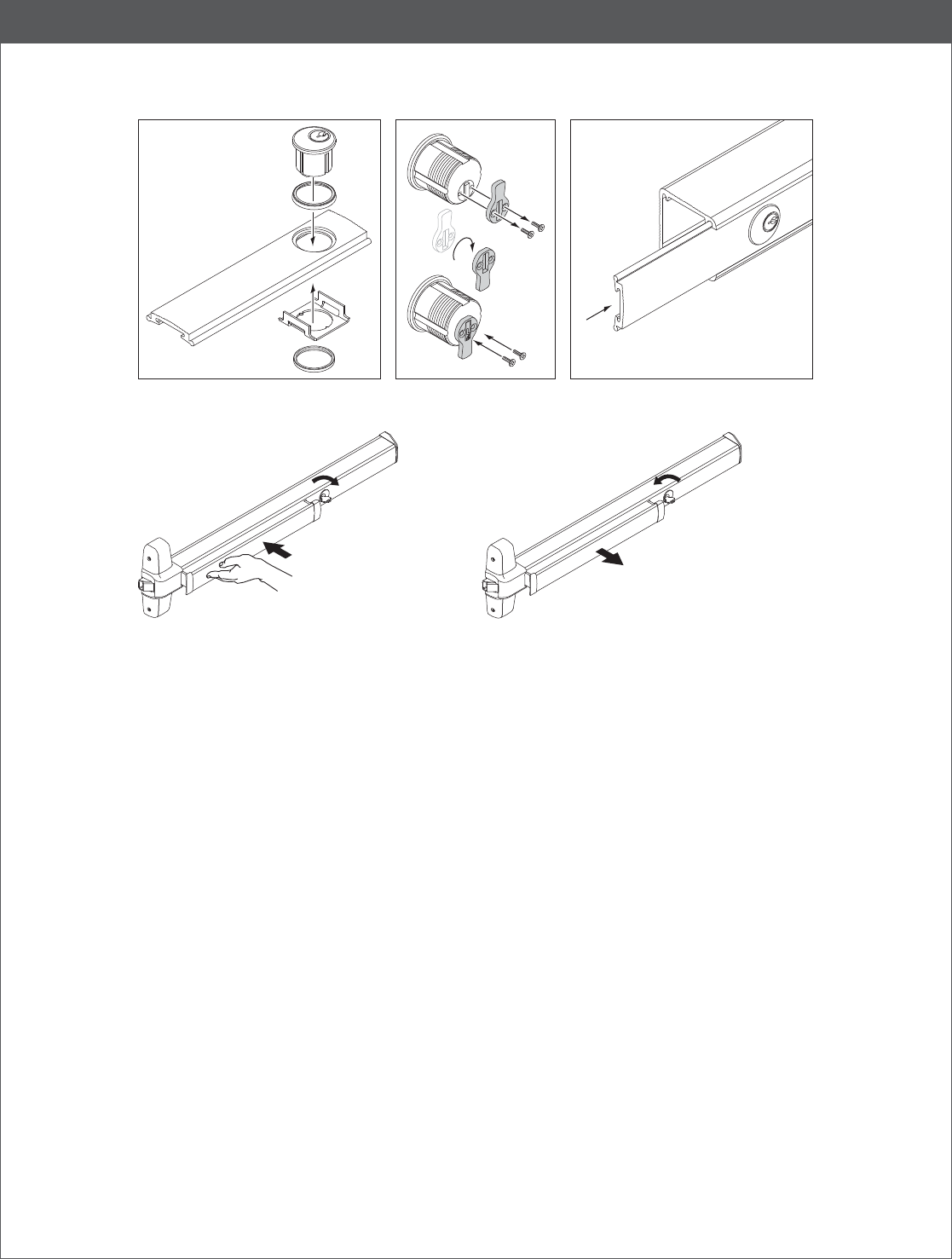
9 If using a cylinder with a tailpiece, prepare device
and cylinder.
9a Install tailpiece guide.
Tailpiece guide
Tailpiece
Rotate tailpiece guide
to match tailpiece
9b Cut tailpiece as needed.
¹⁄₂”
Door
Surface
5
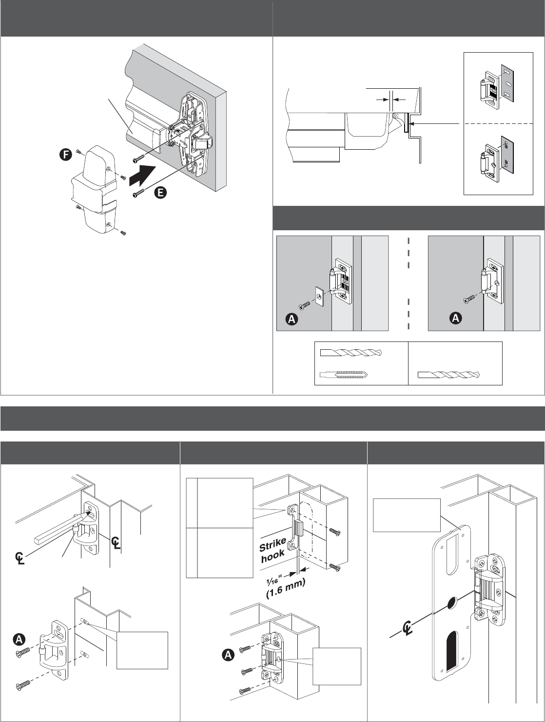
10 If necessary, cut device.
1¹⁄₂” (38 mm)
recommended
Jamb
Jamb
Temporarily remove
anti-rattle clip
Cover plate fl ush
11 Attach center case to door.
OR
Thru-Bolting Trim
Sex BoltsSurface Mount
12 Mark and prepare two (2) holes.
Q Prepare holes after lock side of device is mounted and
hinge side is leveled.
c
b
aSURFACE MOUNT
#25
#10-24
WOOD METALWOOD METAL
¹⁄₈” (3 mm) x 1” (25 mm) Deep
¹³⁄₃₂” (10 mm) Drill Thru
SEX BOLTS
¹⁄₄” (6 mm) Device Side
¹³⁄₃₂” (10 mm) Trim Side
OR
13 Install end cap bracket and end cap.
6
14 Install required support screws and
center case cover.
Remove protective
fi lm from pushbar
15 Adjust strike as needed.
Shim as needed
³⁄₁₆” (5 mm)
299/299F Strike
299
299F
16 Install strike support screw.
OR
#25
#10-24
METAL WOOD
¹⁄₈” (3 mm) x
1” (25 mm) Deep
499F STRIKE INSTALLATION
1. Prepare and install screws through two
strike slots.
2. Install strike hook and additional strike
screws.
3. Template aligns as shown.
Roller
(against door)
Q If using a mullion,
holes may be predrilled
#25 Drill
#10-24 Tap
2 places
#7 Drill
¹⁄₄” (6 mm)-
20 Tap
2 places
¹³⁄₃₂” (10 mm)
Drill thru for
sex bolts
2 places
MetalWood
#25 Drill
#10-24 Tap
3 places
Template
(align on C
L and
against strike
7
OPTIONAL EQUIPMENT
CD (Cylinder Dogging) Option
Dog Undog
a
b
c
d
e
f
8
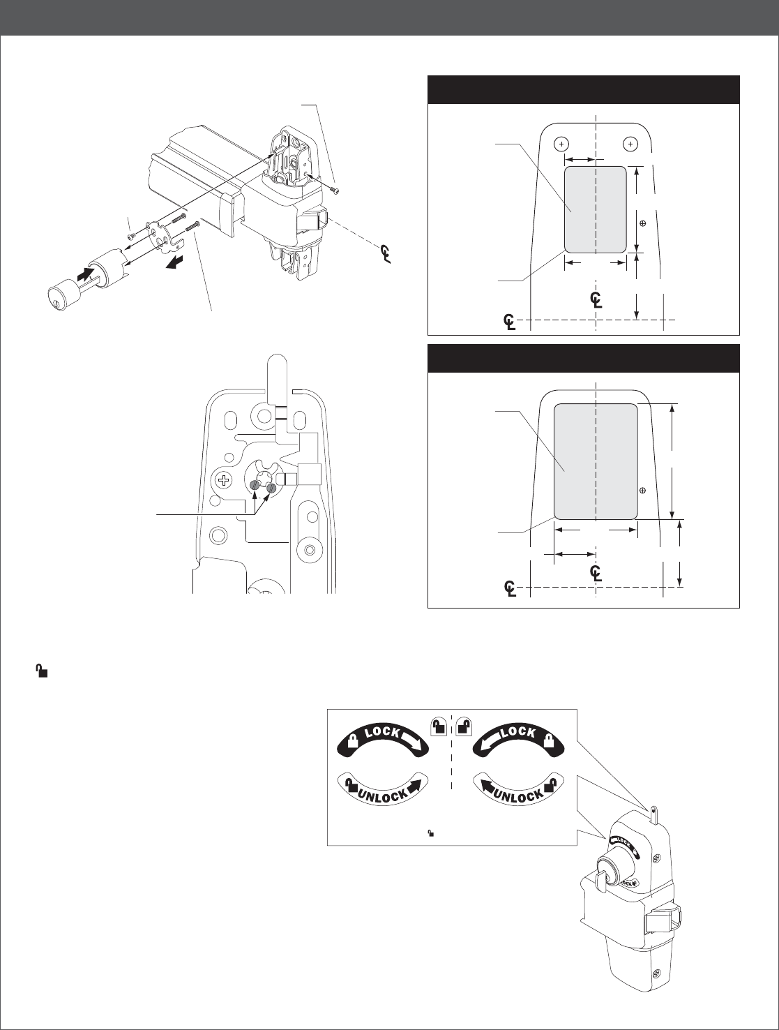
OPTIONAL EQUIPMENT
99-2 (Double Cylinder) Option
If using the -2SI with a
keyed rim cylinder,
remove the 2 stop screws
from back of device prior
to installing the cylinder.
⁵⁄₈” (16 mm)
1³⁄₄” (44 mm)
1³⁄₈” (35 mm)
1¹⁄₄”
(32 mm)
Wood
¹⁄₄” (6 mm)
Deep
#8-32 x ⁵⁄₁₆” (8 mm)
PPHMS
a
b
d
Cylinder
Mounting Screws
DO NOT over-tighten
RHR Shown
(LHR opposite)
c
e
#8-18 x ³⁄₈” (10 mm)
PPHSMS
2¹⁄₄” (57 mm)
1³⁄₈” (35 mm)
¹³⁄₁₆” (21 mm)
Device
and Strike
1⁵⁄₈”
(41 mm)
Wood
¹⁄₄” (6 mm)
Deep
Device
and Strike
Door Cutout for 99-2 “Double Cylinder” Option
Door Cutout for 99-2SI “Double Cylinder” Option
¹⁄₈” (3 mm) R
4 places
¹⁄₈” (3 mm) R
4 places
For 98/99-2SI models with Classroom Security Indicator, apply supplied labels above and below cylinder to match door handing,
and label on indicator.
Q Manually affi x the label:
Ensure surface is clean of dirt, dust, or oils. Clean with alcohol
if necessary.
Peel the label from the paper backing and apply to the surface.
Minimize handling when applying and use pressure to burnish
label to surface. The adhesive will require up to 8 hours to
achieve the proper bond. RHR shown
Peel and stick
appropriate set of
labels depending on
door handing. Stick labels
above and below cylinder,
and label on indicator.
LHR99-2 RHR99-2
