Von Duprin LBR Auxiliary Fire Pin And 499F Strike Installation Instructions 107570
User Manual: Von Duprin LBR Auxiliary Fire Pin and 499F Strike Installation Instructions Installation Instructions
Open the PDF directly: View PDF ![]() .
.
Page Count: 8
911010-00
NOTE
!
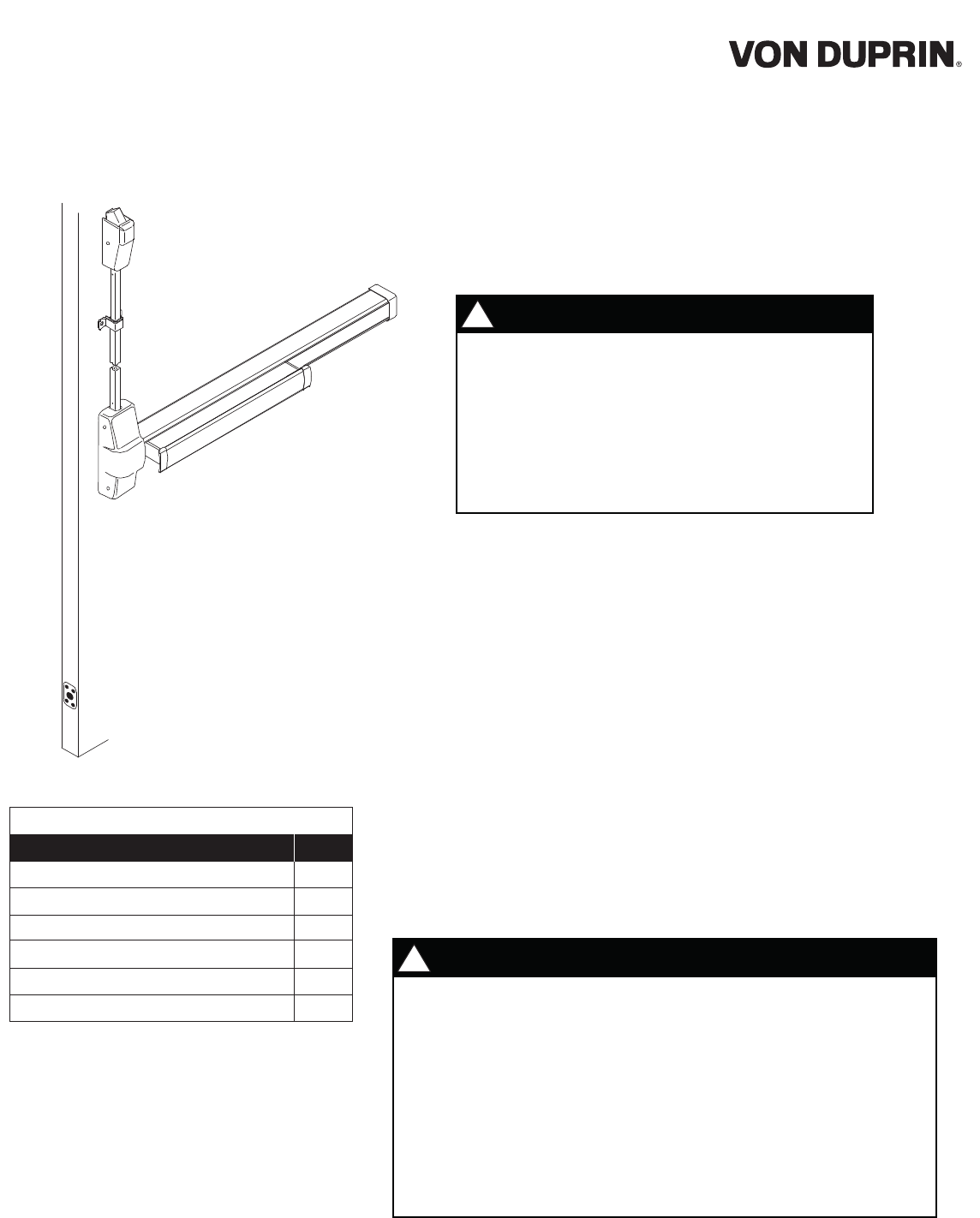
One (1) auxiliary fire pin assembly is supplied with two LBR devices. It
does not matter which door leaf the auxiliary fire pin is installed on.
However, the pin must be installed to maintain the fire listing. The
purpose of the auxiliary fire pin assembly is to keep the doors in
alignment during a fire. In a fire, the bolt extends from the auxiliary fire
pin into the strike hole in the opposite door leaf. The black cap visible
on the face of the auxiliary fire pin and the strike hole plug must melt in
order for the bolt to extend. If an Edge Guard is used, make sure it is
modified to allow clearance for the Fire Pin and Plastic Cap to be
mounted to the door edge after the Edge Guard is installed. See Edge
Guard Preparation on page 4 for more information.
WARNING
!
For surface vertical rod installations, incorrect strike
installations can result in latching failure in a fire
condition. This can result in severe injury or death.
Installer: Discard installed strikes and replace with
correctly installed 499F strikes supplied with this kit.
Failure to install the 499F strikes on Surface Vertical
Rod LBR-F devices will void the UL Fire Label.
LBR
(Less Bottom Rod)
LBR Fire Pin/Strike Kit is for use only with Von Duprin 98/9927-F,
98/9947-F, 33/3547-F, 33/3527A-F, 33/3547A-F, and 2227-F devices.
Any door preparation must be performed by an installer that is
certified by the door manufacturer.
Installation of device with 499F strike for surface vertical rod
devices, and 338 strike for concealed vertical rod devices is
required to maintain fire listing. For 499F installation, see page
3 of these instructions.
1.
2.
3.
Important:
Read this first!
Auxiliary Fire Pin Assembly
#6 x 3/4” Sheet Metal/Wood Flat Head Screw
Strike Hole Plug
499F Strike Assembly
Return Spring
Centercase Hole Plug
Description
Parts List
Quantity
1
4
1
2
2
2
Fire Pin/Strike Kit
LBR
Installation Instructions
2
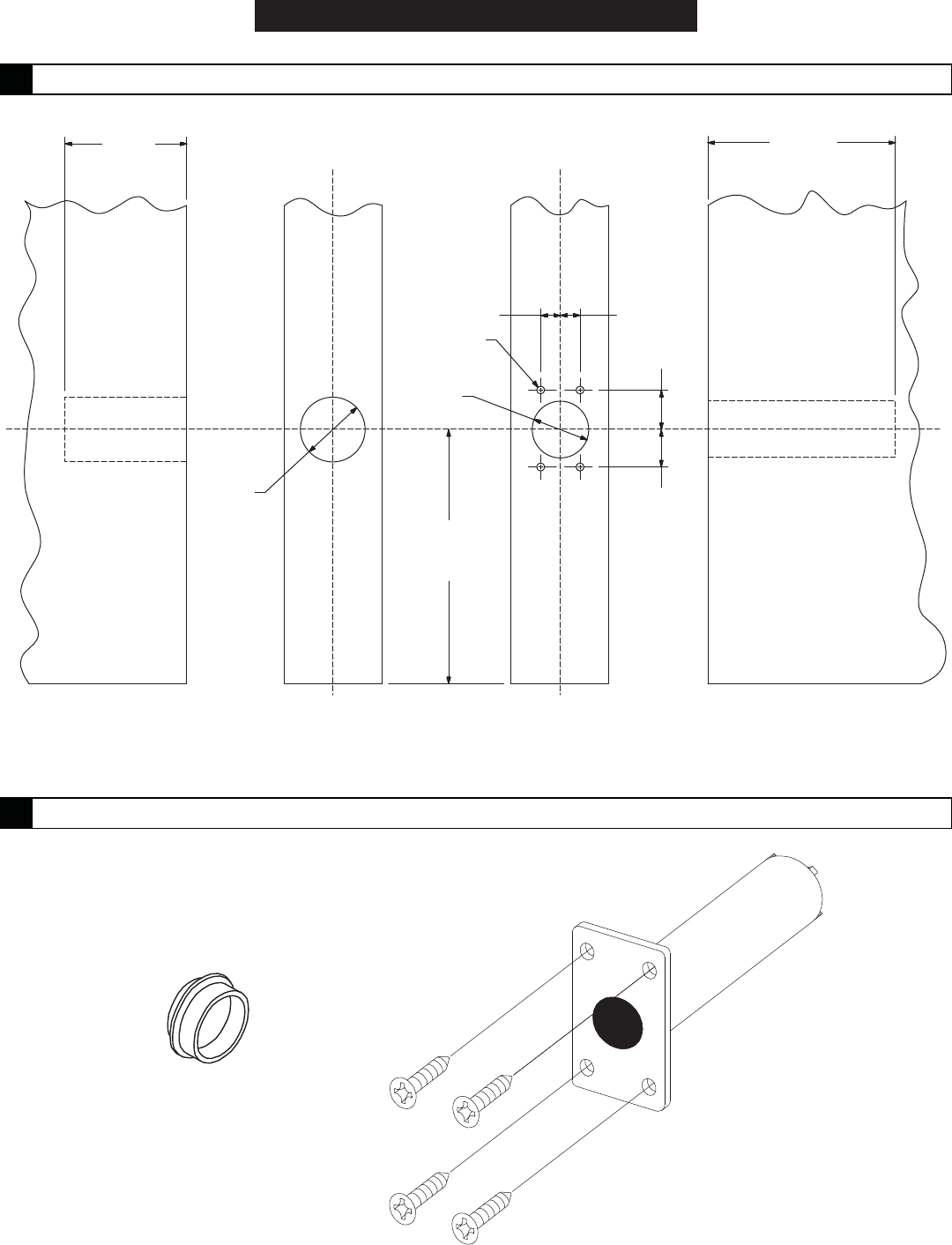
1 3/4"
depth of hole
C
L
C
LC
L
C
LC
L
C
L
1" dia.
roodrood
roodrood
3 3/8"
depth of hole
1/4"1/4"
#36 drill
4 places
7/8" dia.
6" from
bottom
of door
5/8"
5/8"
Strike Hole Plug
Door Leaf Auxiliary Fire Pin
Door Leaf
2 Install strike hole plug and auxiliary fire pin.
Install strike hole
plug in strike hole
Mount auxiliary fire pin
with four #6 x 3/4" Type AB
flat head screws
1 Prepare auxiliary fire pin mounting hole, screw holes, and strike hole in door.
INSTALLATION
3
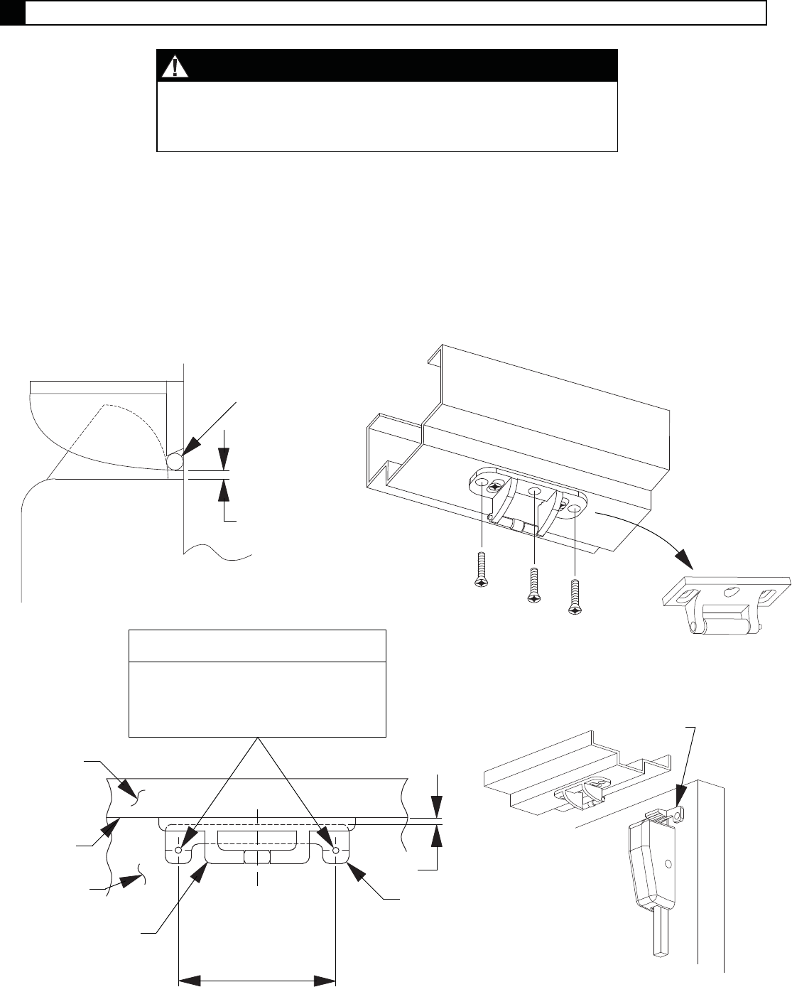
3.1. Replace 299F strikes with 499F strikes as shown below.
3.2. Adjust 499F strike to position shown in Figure 3-1.
3.3. Install remaining three screws (see Figure 3-2).
3.4. Prepare door for strike hook (see Figure 3-3) and install strike hook. Figure 3-4 shows relative
positions of strike, strike hook, and top latch.
Figure 3-1
1/16" ref.
Strike roller
#25 drill and
#10-24 tap
(3 places)
Figure 3-2
Figure 3-4
Strike hook
Figure 3-3
Center strike hook
on strike, locate to
1/16" dimension,
and mark holes
C strike
L
1/16"
Strike
hook
Strike
Face
of stop
Face
of door
Hole Schedule
Metal door: #7 drill and #1/4"-20 tap
Wood door: 13/32" dia. drill thru
Bottom
of stop
NOTE
The 499F strike installation is only for 98/9927-F-LBR,
33/3527A-F-LBR, and 2227-F-LBR devices. For concealed
vertical rod LBR devices, skip this procedure.
3 Install 499F strike.
Remove
299F strike
4
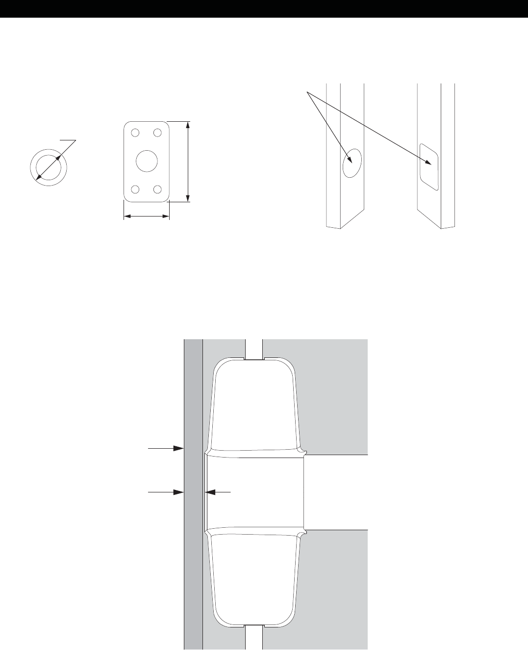
EDGE GUARD PREPARATION
Edge of door
Maximum .0625"
from edge of door to
edge of device
If using Edge Guards, clearance holes must be cut into Edge Guards before they are installed on door as
shown in Figure 4-1.
Edge guard near exit device center case can extend no further than .0625" from edge of door, as shown in
Figure 4-2, or interference with device center case could occur. If Edge Guard is wider than specified, it may
need to be trimmed in that area to clear center case.
Figure 4-2
Figure 4-1
1.000"
1.765"
1.188"
Edge Guard
clearance holes
Outer Dimensions
of plug and strike
5
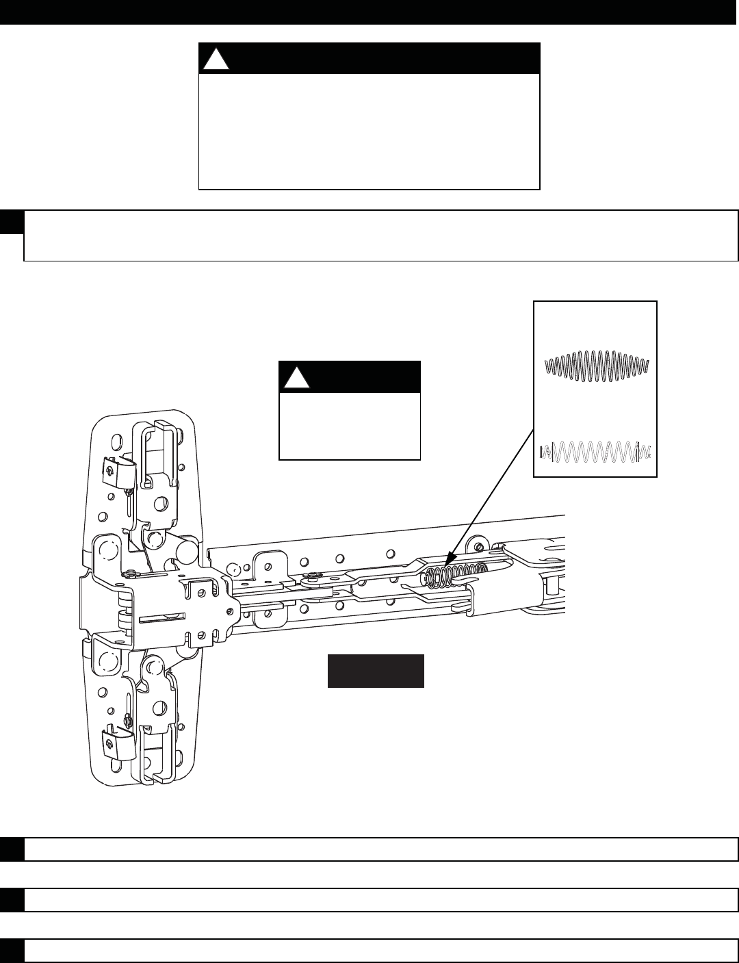
RETURN SPRING REPLACEMENT
WARNING
!
Installation of the wrong spring can result in latching
failure in a fire condition. This can result in severe
injury or death.
Installer: Make sure correct return spring is installed
per instructions below.
1Determine which spring the device baseplate contains comparing to the following
two springs:
2 Remove return spring "A" and replace with spring supplied in kit.
3 Repeat steps 1 and 2 for device on other door leaf.
4 Reinstall devices.
Spring A
Spring B
NOTE
!
If device contains
Spring "B" skip to
Step 3.
9927-F
6
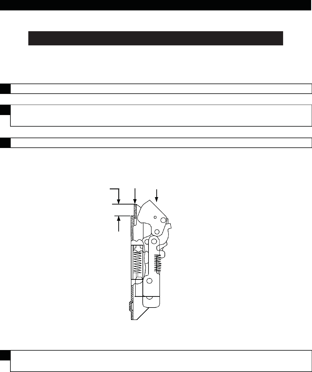
VERTICAL ROD ADJUSTMENT PROCEDURE
2Push rod upward slowly until it has fully extended top latch bolt to achieve
deadlocking as shown.
4Check device operation by opening and closing door with outside lever or
thumbpiece.
1 Screw top vertical rod to top latch case.
3 Adjust top vertical rod until rod snaps into centercase.
33/3527A-F-LBR, 98/9927-F-LBR, & 2227-F-LBR
Hold
down Push to check
deadlocking
3/16"
7
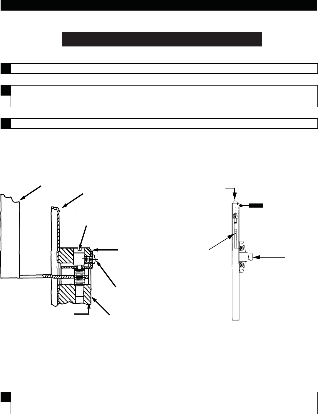
VERTICAL ROD ADJUSTMENT PROCEDURE
2Rotate adjusting screw clockwise until centercase adjustment block begins to move
down and top latch bolt is fully extended (do not remove retaining clip).
4Check device operation by opening and closing door with outside lever or
thumbpiece.
1 Loosen top adjustment lock screw.
3 Set adjusting screw as shown. Tighten adjustment lock screw.
33/3547A-F-LBR & 98/9947-F-LBR
Top Rod (9947-F shown)
Centercase
Adjusting
Screw
Retaining
Clip
Adjustment
Lock Screw
on Flat
Rod Actuating Link
(9947-F shown)
Centercase
Adjustment Block
Depress
to check
deadlocking Depress in hole
with screwdriver
to release latch
bolt
Top rod
assembly Touch Bar
© Allegion 2015
Printed in U.S.A.
911010-00 Rev. 06/15-e
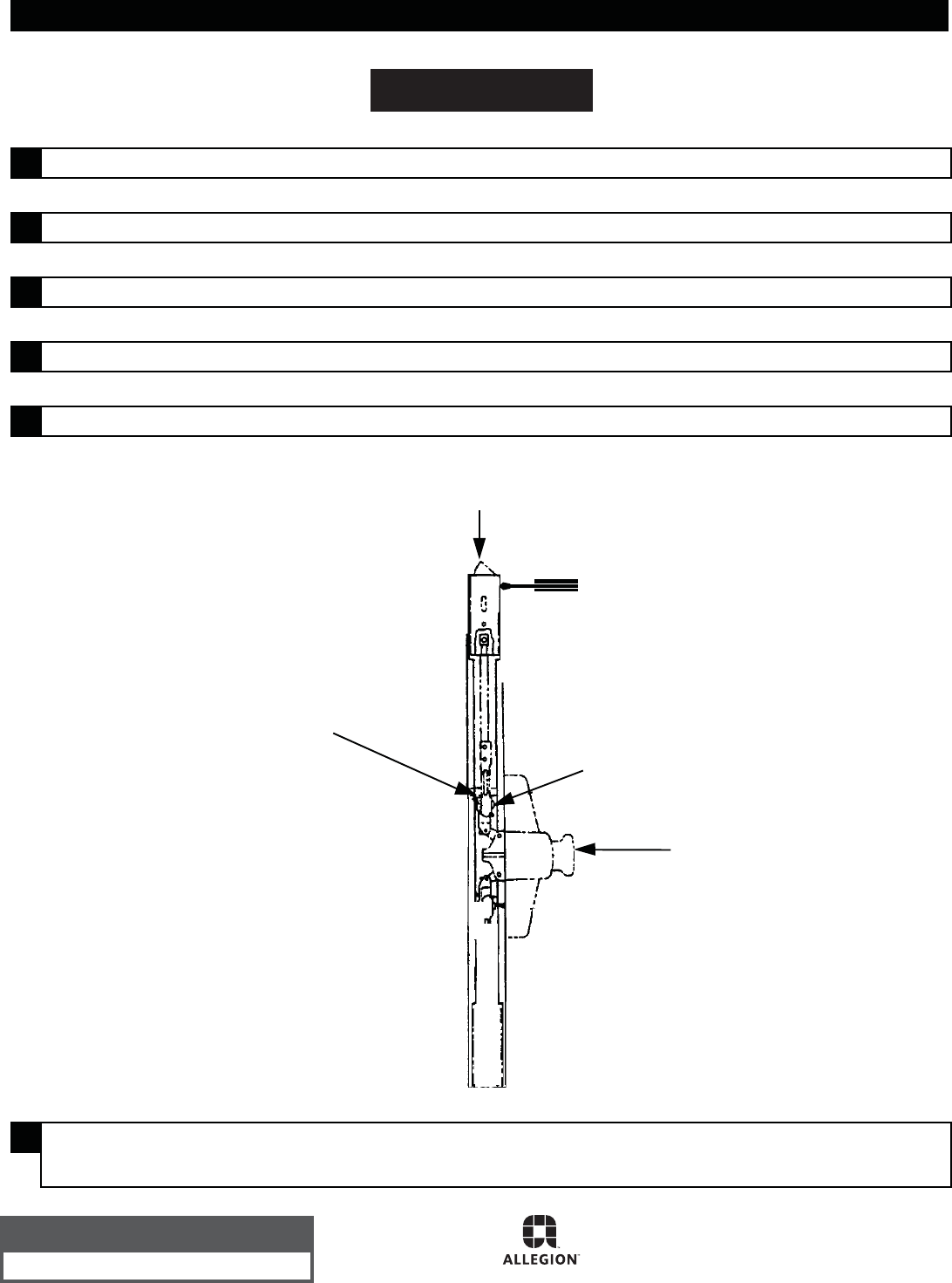
VERTICAL ROD ADJUSTMENT PROCEDURE
6Check device operation by opening and closing door with outside lever or
thumbpiece.
1 Loosen top adjustment linkage screw on top connector as shown in the diagram.
3 Open door and release pushbar. Top latch bolt should be held retracted.
2 Fully extend latch bolt. Retighten top adjustment linkage screw.
4 Release latch bolt as shown.
5 Check deadlocking.
3347F-LBR
Depress to
check deadlocking
Teeth must mesh
properly
Touch Bar
Top Adjustment
Linkage Screw
Depress in hole with
screwdriver to
release latch bolt
Customer Service
1-877-671-7011 www.allegion.com/us
