Voxx Electronics DEIBLE1 Bluetooth Low Energy Limited Modular Transceiver User Manual
DEI Headquarters, Inc. Bluetooth Low Energy Limited Modular Transceiver Users Manual
UserManual.wiki
>
Voxx Electronics
>
DEIBLE1 User Manual
Users Manual
Navigation menu
Upload a User Manual
Namespaces
Wiki Guide
HTML
PDF
Info
Views
User Manual
Discussion / Help
Navigation

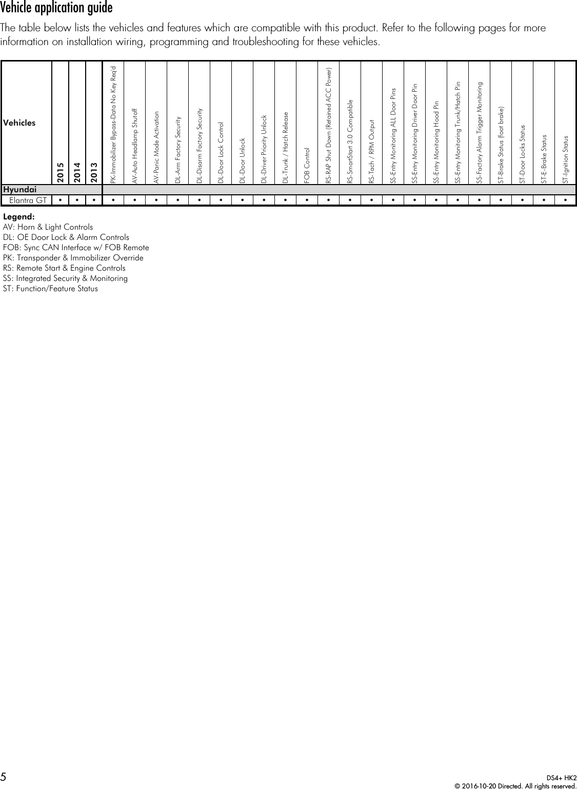
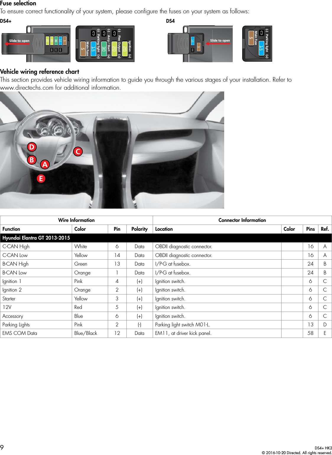
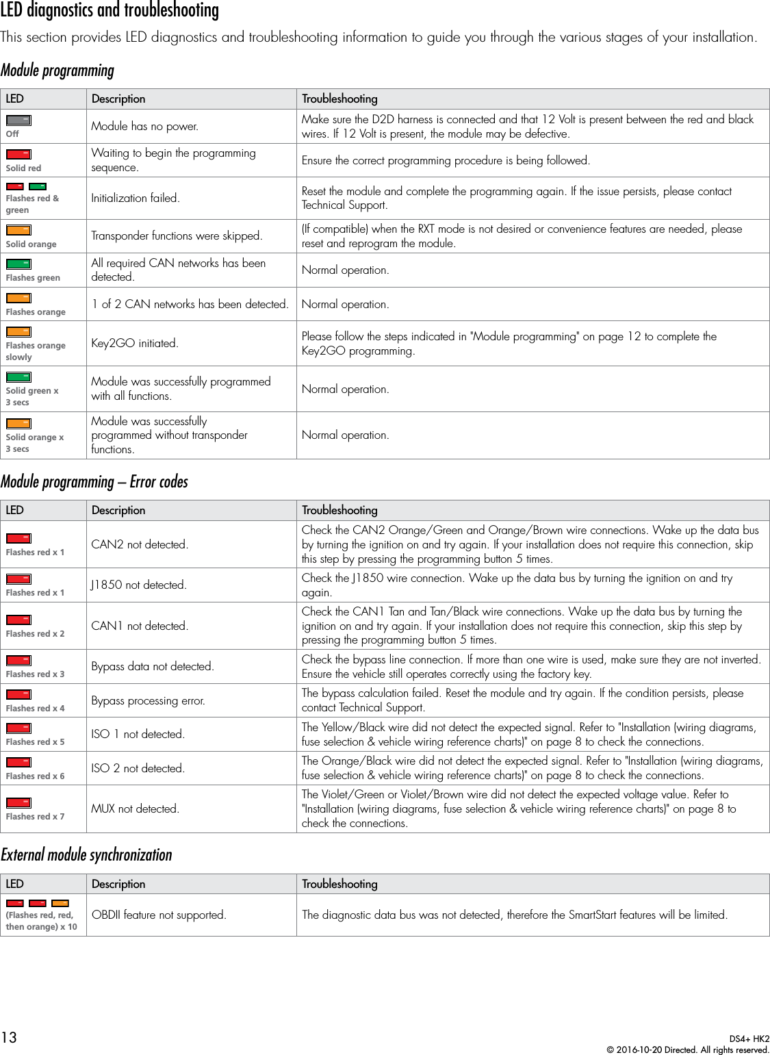
![4DS4+ HK2© 2016-10-20 Directed. All rights reserved.IntroductionThe HK2 firmware for DS4+ is a complete solution for remote start, security (if applicable), bypass interface, and convenience needs compatible with specific Hyundai vehicles.Warning! This module can only be programmed via the web tool, which can be found on www.directechs.com or using the Directechs Mobile application for smartphones. Features and functions will become accessible when you connect the module using the XKLoader.Pre-installation and application warningsFirmware notes: This section highlights important information for this specific firmware and will assist in pricing accordingly, as well as bringing awareness to any operational or vehicle limitations.T-HarnesscompatibleKeys required for programming 1Keys required for operation 0 Unless specified otherwise, all connectors are displayed from the wire side, with the exception of the OBDII diagnosticconnector. It is important to check that the fuses are positioned correctly in the module. Refer to the "Fuse selection" section followingeach installation type for more information. Refer to the "Vehicle wiring reference chart" following each installation type.General notes: This section highlights important information for this specific firmware.[1] The installation of an aftermarket hood pin is only required on vehicles that are not equipped with a factory hood pin.[2] The siren is only compatible with the Directed Digital remote start and security system.[3] The Green wire is only required for starter disable and antigrid connections.Additional parts required (maximum required): Diode 6A0 x 1A Diodes 86 853087a870 x RelayResistor 100Ω0 x ResistorFuse 7.5A0 x Fuse](https://usermanual.wiki/Voxx-Electronics/DEIBLE1/User-Guide-3170981-Page-5.png)