Vytek PC-UC-2 Base Station Irrigation Control Module User Manual 1
Vytek Inc Base Station Irrigation Control Module Users Manual 1
UserManual.wiki
>
Vytek
>
PC-UC-2 User Manual
>
Users Manual 1
Contents
1.
Users Manual 1
2.
Users Manual 2
Users Manual 1
Navigation menu
Upload a User Manual
Namespaces
Wiki Guide
HTML
PDF
Info
Views
User Manual
Discussion / Help
Navigation
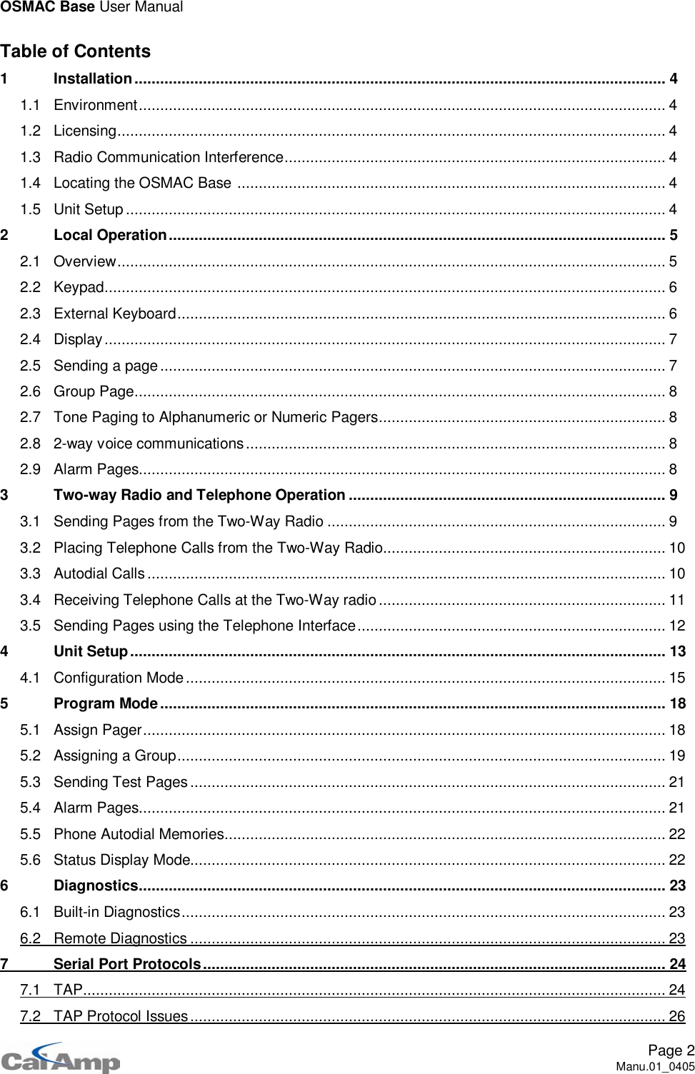
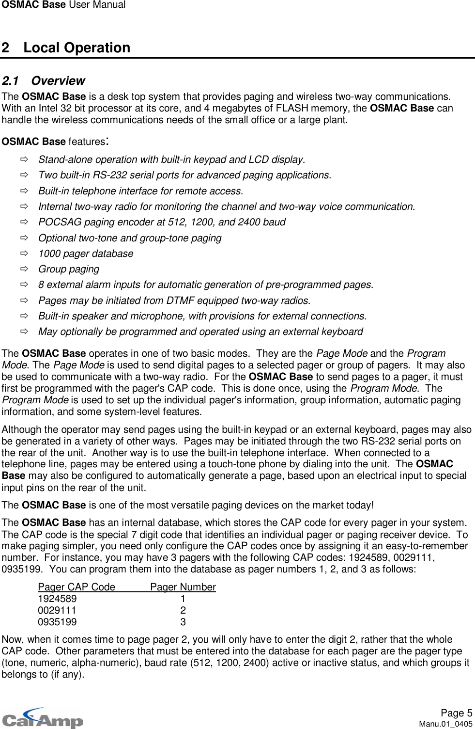
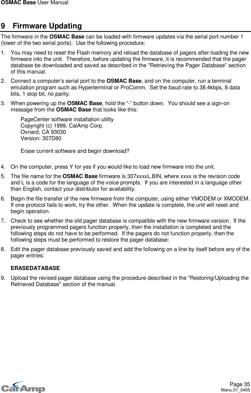
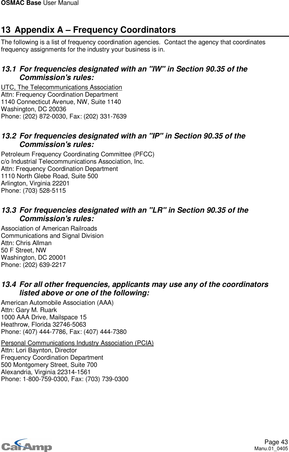
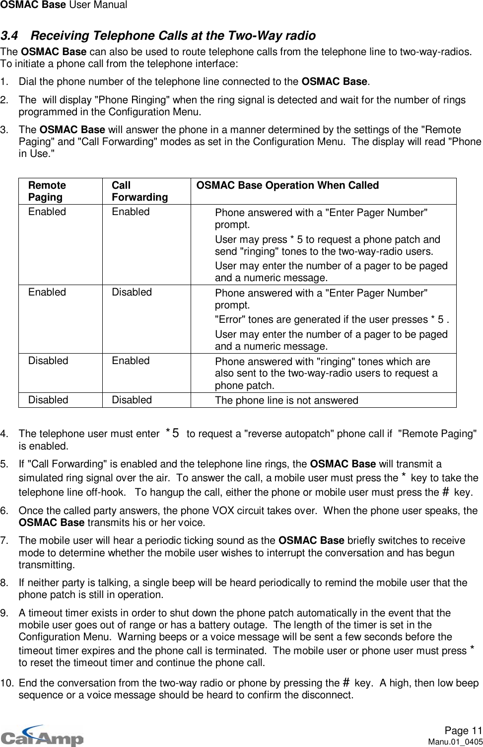
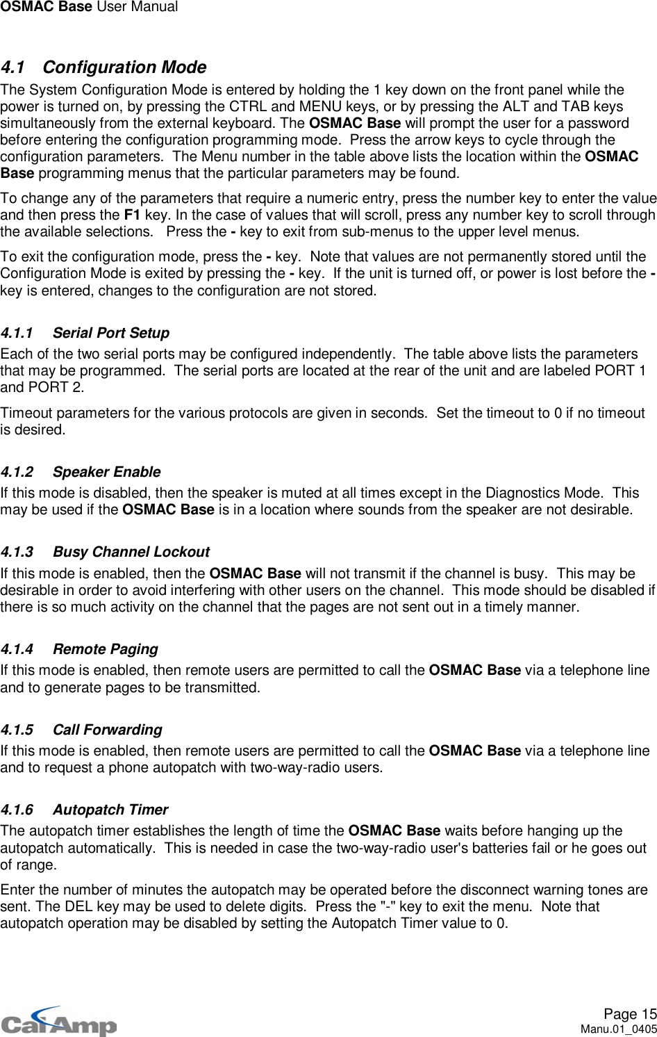
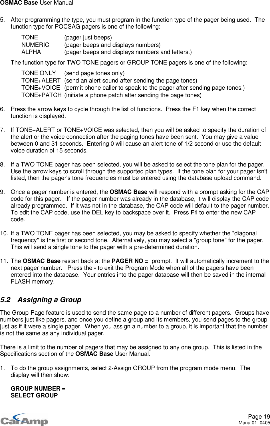
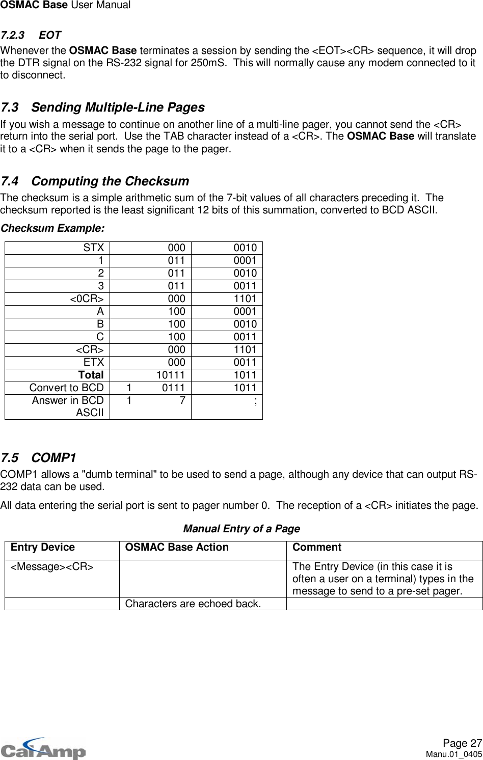
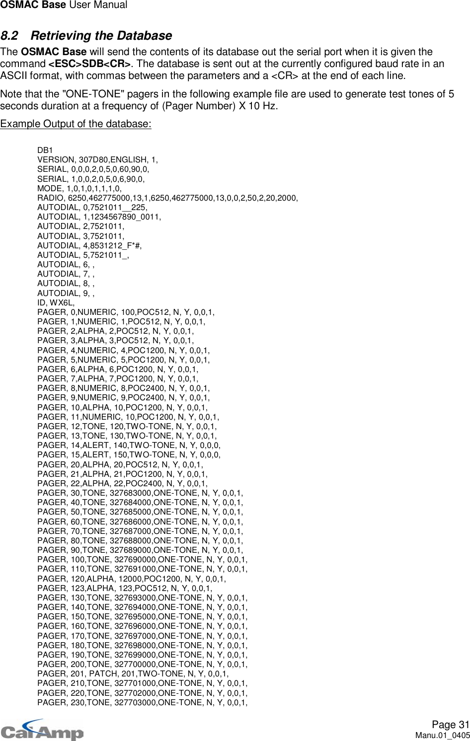
![OSMAC Base User ManualPage 7Manu.01_0405IMPORTANT NOTE: Some keyboards are extremely sensitive to the high RF fields present when anantenna is connected directly to the rear of the OSMAC Base . The keyboard may stop functioningproperly after the OSMAC Base transmitter is turned on. If this situation occurs, it is recommended thatthe antenna be mounted at least several feet from the OSMAC Base or that a different brand of keyboardbe used.2.4 DisplayThere is a two-line, twenty-character LCD display on the OSMAC Base. The three LEDs on the top rightside of the unit indicate the state of the transmitter, whether the channel is busy, and the programmingmode.2.5 Sending a pageThe OSMAC Base is ready to send a page when the LCD display shows:This means the OSMAC Base is waiting for you to enter the pager number to which you which to send apage. Using the keypad or an external keyboard, enter the number (not the CAP code) of the pager youwish to page. Once you enter the pager number, press the F1 key. There are three standard types ofpagers supported by the OSMAC Base. They are: tone-only, numeric and alpha-numeric. An option isavailable which supports two-tone pagers as well. Depending upon what type of pager you are sendingthe page to, one of the following sequences will take place:1. POCSAG tone-only pagersIf the pager is a tone-only type, it does not have a display. A page sent to it will cause it to beep.When a page is sent to it, the display will show TONE PAGER while it is sending the page over-the-air to the pager. This will take about one second, after which it will display PAGE ACCEPTED for acouple seconds, and then return back to the PAGER NO= prompt.2. Numeric and alpha-numeric pagersIf the pager is designated as a Numeric pager or an Alphanumeric pager in the OSMAC Basedatabase, then the LCD display will show NUMERIC PAGER or ALPHA PAGER for one second, andthen the LCD display will show ENTER MESSAGE. The user enters the message using the keypadinto line 2 of the display. If the message is longer than the length of the display, the display willautomatically scroll down to the next line as the message is entered. Pressing the DEL key deletesthe previous character entered. Once the data is entered, press the F1 key to send the page. Thedisplay will show PAGE ACCEPTED for a couple seconds and then the display will return back to thePAGER NO= prompt.Note that: Only messages with numbers may be sent when using the built-in keypad. Alphanumeric messages may be sent to alphanumeric pagers when using an external keyboardor the computer interface. The POCSAG characters "[", "]", "-", "space" and "U" may be sent to numeric pagers when usingthe external keyboard, mobile radio or the computer interface.3. Two-tone pagersTwo-tone pagers accept a sequence of two tones. The CAPCODE is a number between 0 and 999.A large number of standard tone plans are supported by the OSMAC Base. Pagers with non-standard tone frequencies may be programmed via the database upload command. After the pagingtones are sent, an alert sound or a voice message from the telephone interface or console mayoptionally be sent to the pager. Alternatively, the phone patch may be initiated.PAGER NO =](https://usermanual.wiki/Vytek/PC-UC-2.Users-Manual-1/User-Guide-614496-Page-7.png)
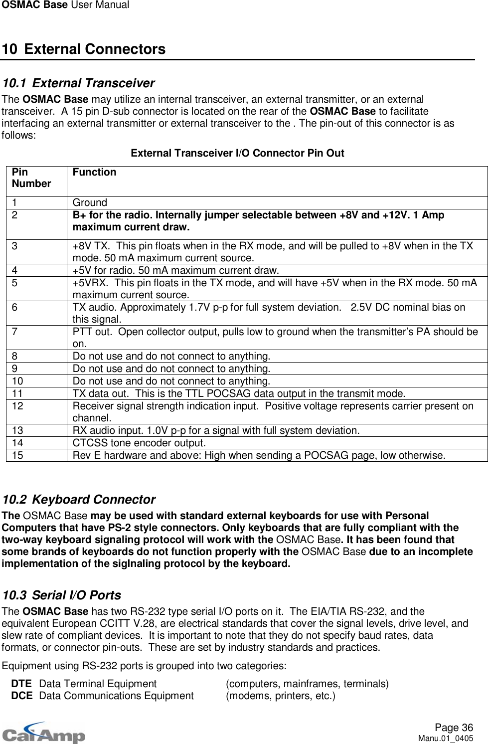
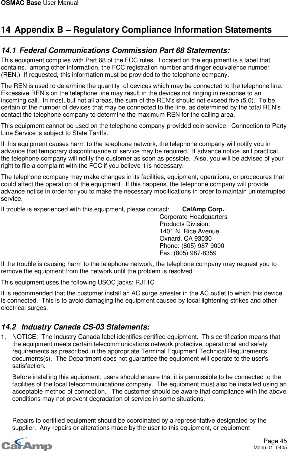
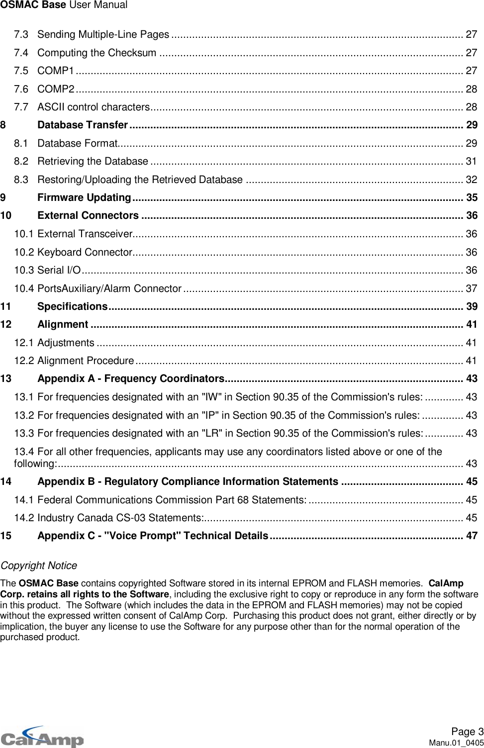
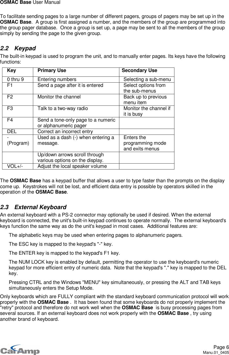
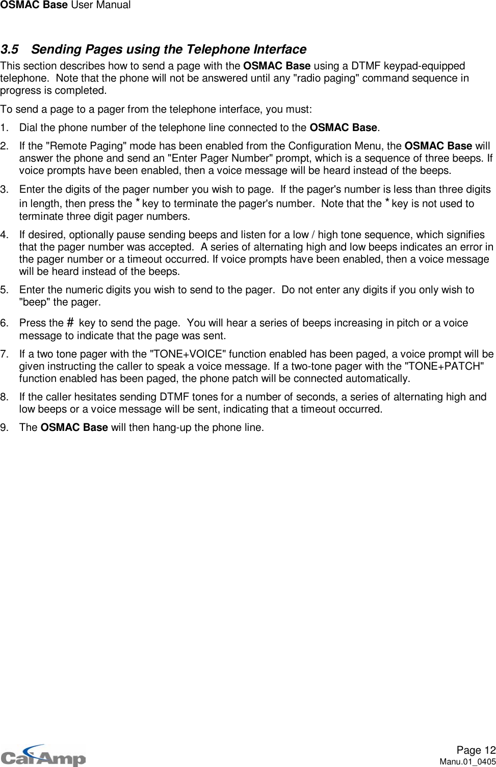
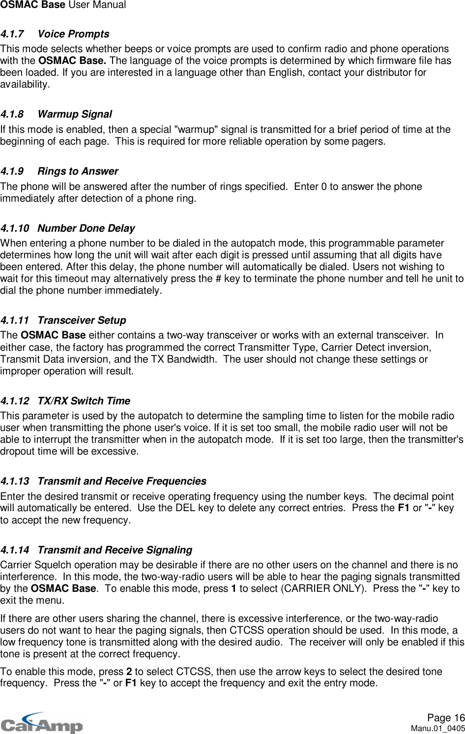
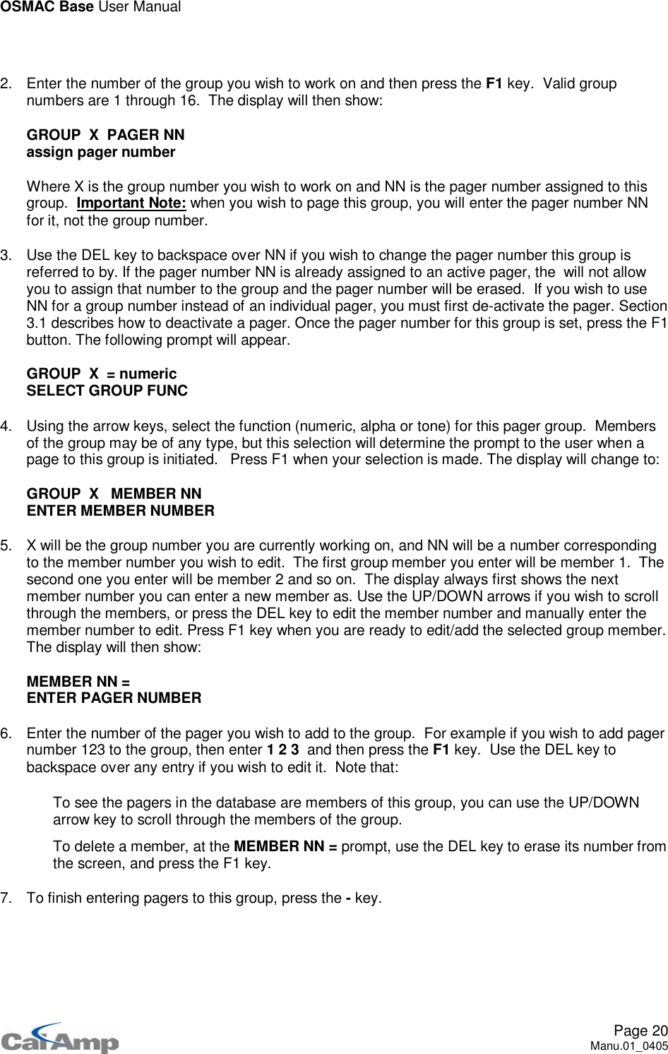
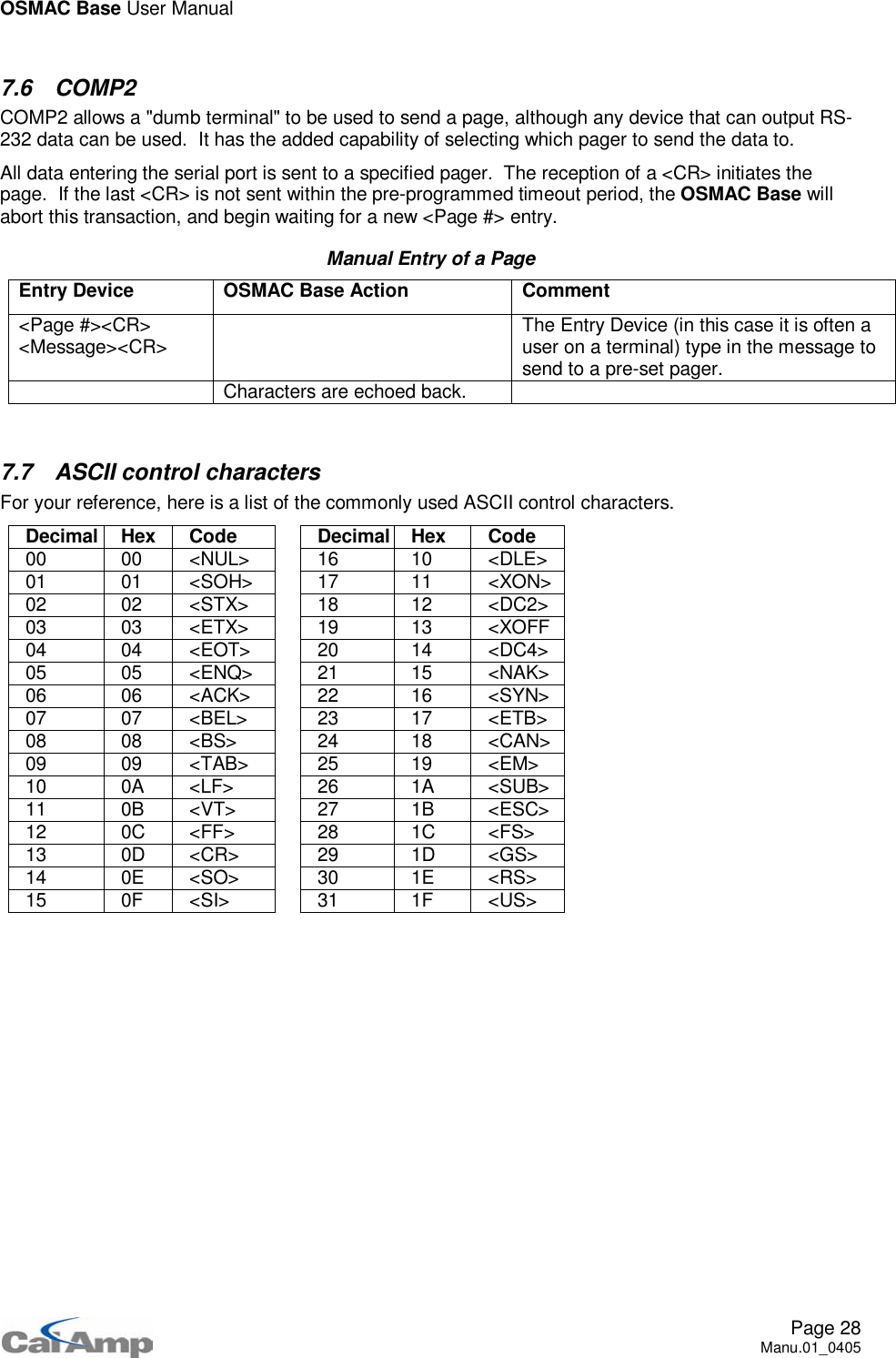
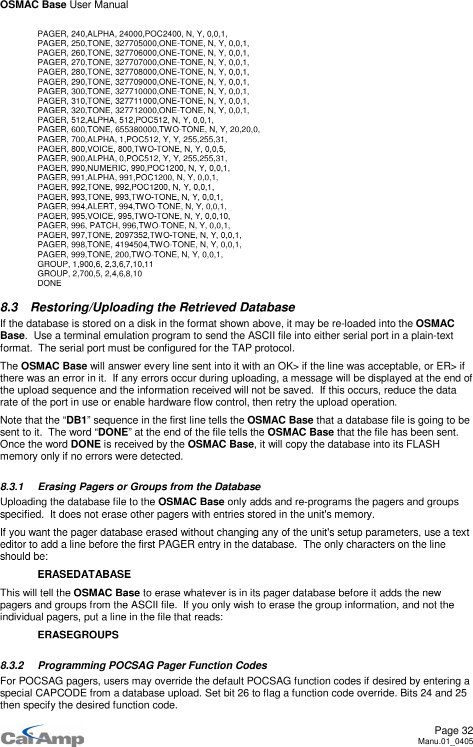
![OSMAC Base User ManualPage 9Manu.01_04053 Two-way Radio and Telephone OperationThe OSMAC Base has a built-in radio transceiver enabling it to communicate with other two-way radiosand to receive over-the-air commands to generate pages, connect to the telephone system, dial phonenumbers and answer incoming telephone calls. The telephone interface may be utilized for generatingpages or initiating phone patches with two-way-radios.To remotely control the OSMAC Base with a two-way radio or from a telephone, the two-way radio ortelephone must be equipped with a DTMF encoder. All commands sent to the OSMAC Base are enteredvia the DTMF keypad, and in most cases, the commands are similar to the ones used locally on theOSMAC Base's built-in keypad. During two-way radio operations, the OSMAC Base will not transmitpages. Any pages entered by the front panel, external keyboard or computer ports will be queued andsend later, when the radio is idle.3.1 Sending Pages from the Two-Way RadioThis section describes how to send a page with the OSMAC Base using a DTMF keypad-equipped two-way radio. The OSMAC Base and the two-way radio must have previously been configured tocommunicate on the same channel, and utilize the same CTCSS tones.To send a page to a pager from the two-way radio, you must:1. Send *9 to alert the OSMAC Base that you intend to send a page.2. If desired, optionally listen to the receiver for the "Enter Pager Number" prompt, which is a sequenceof three beeps. A series of alternating high and low beeps indicates an error in the commandsequence or a timeout occurred. If voice prompts have been enabled, then a voice message will beheard instead of the beeps.3. Enter the digits of the pager number you wish to page. If the pager's number is less than three digitsin length, then press the *key to terminate the pager's number. Note that the *key is not used toterminate three digit pager numbers.4. If desired, optionally listen to the receiver for a low / high beep sequence, which signifies that thepager number was accepted. A series of alternating high and low beeps indicates an error in thepager number or a timeout occurred. If voice prompts have been enabled, then a voice message willbe heard instead of the beeps.5. Enter the numeric digits you wish to send to the pager. Do not enter any digits if you only wish to"beep" the pager. Note that the following DTMF keys have special meanings:DTMF Key Pager Character Comments* - Hyphen character# {none} Send the pageA Space characterB ] Right bracketC [ Left bracketD U Urgency indicator6. Press the #key to send the page.To send a new message to the same pager again, you may:1. Type *0 to alert the OSMAC Base that you intend to send a page to the same pager number asbefore.2. Continue from step 4 of the instructions above to input the new message to be sent.](https://usermanual.wiki/Vytek/PC-UC-2.Users-Manual-1/User-Guide-614496-Page-9.png)
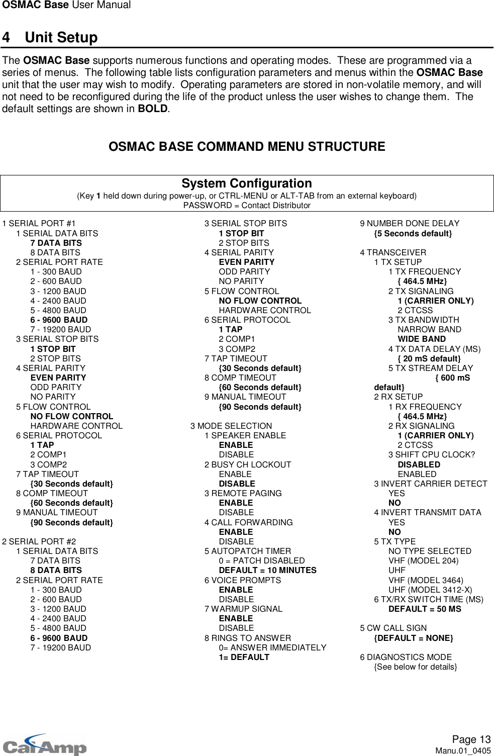
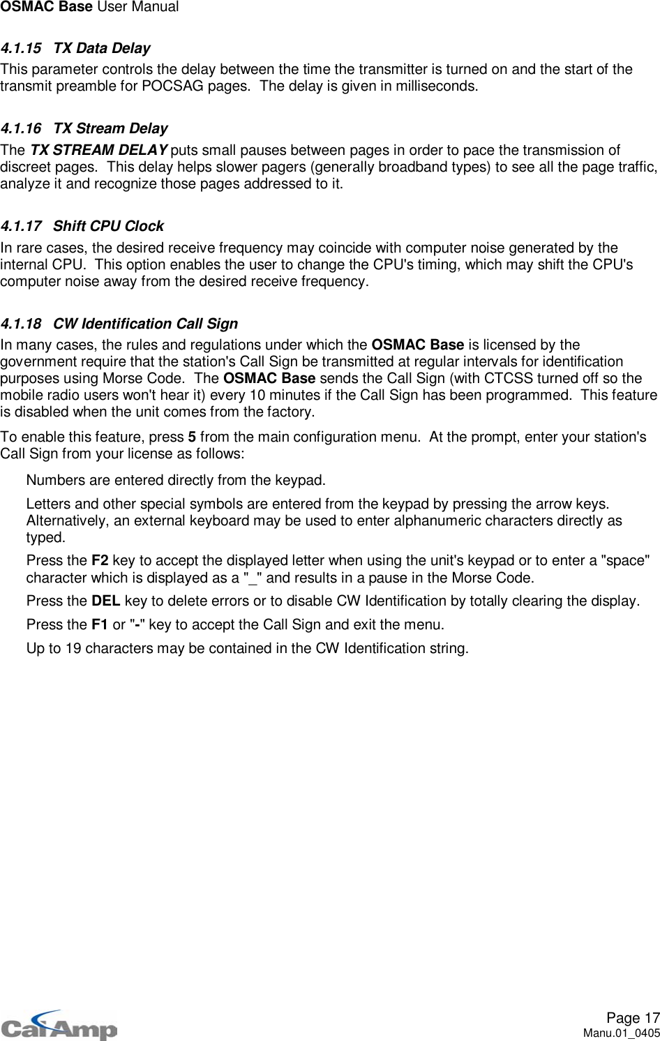
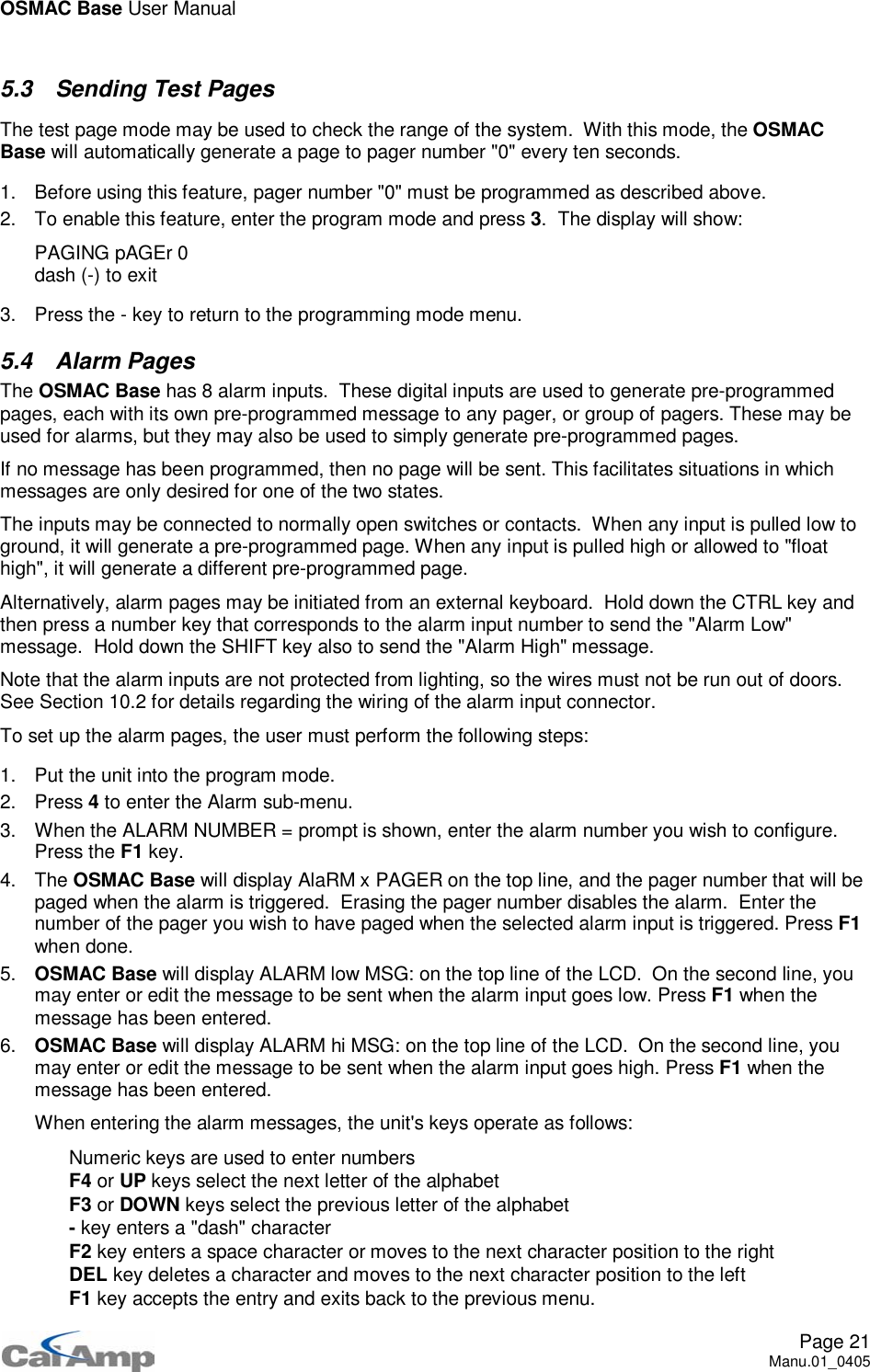
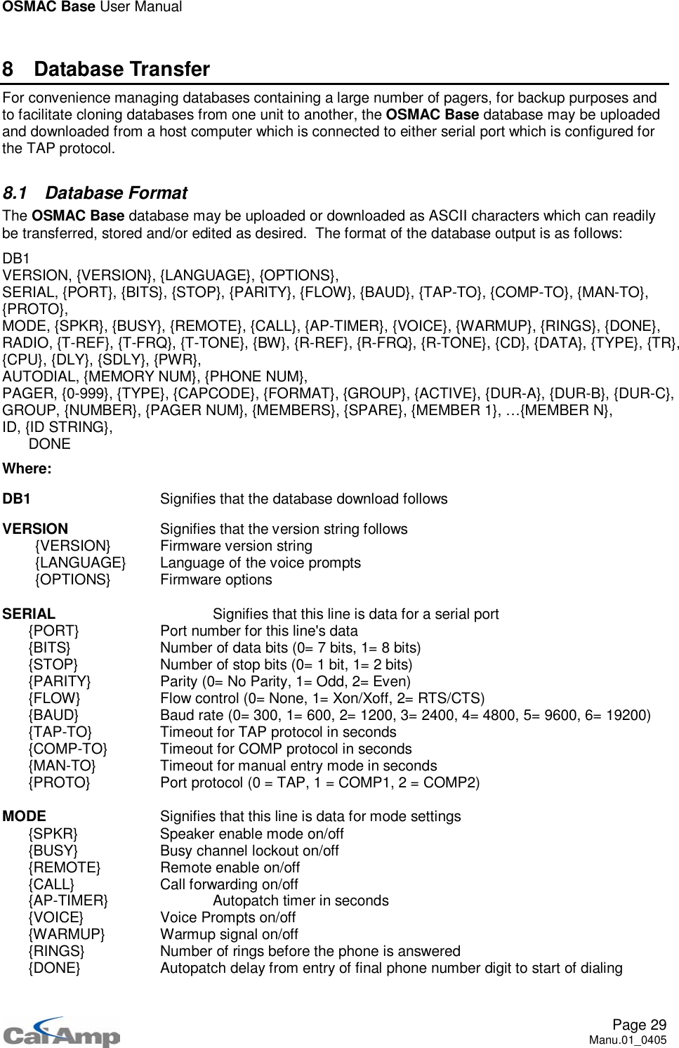
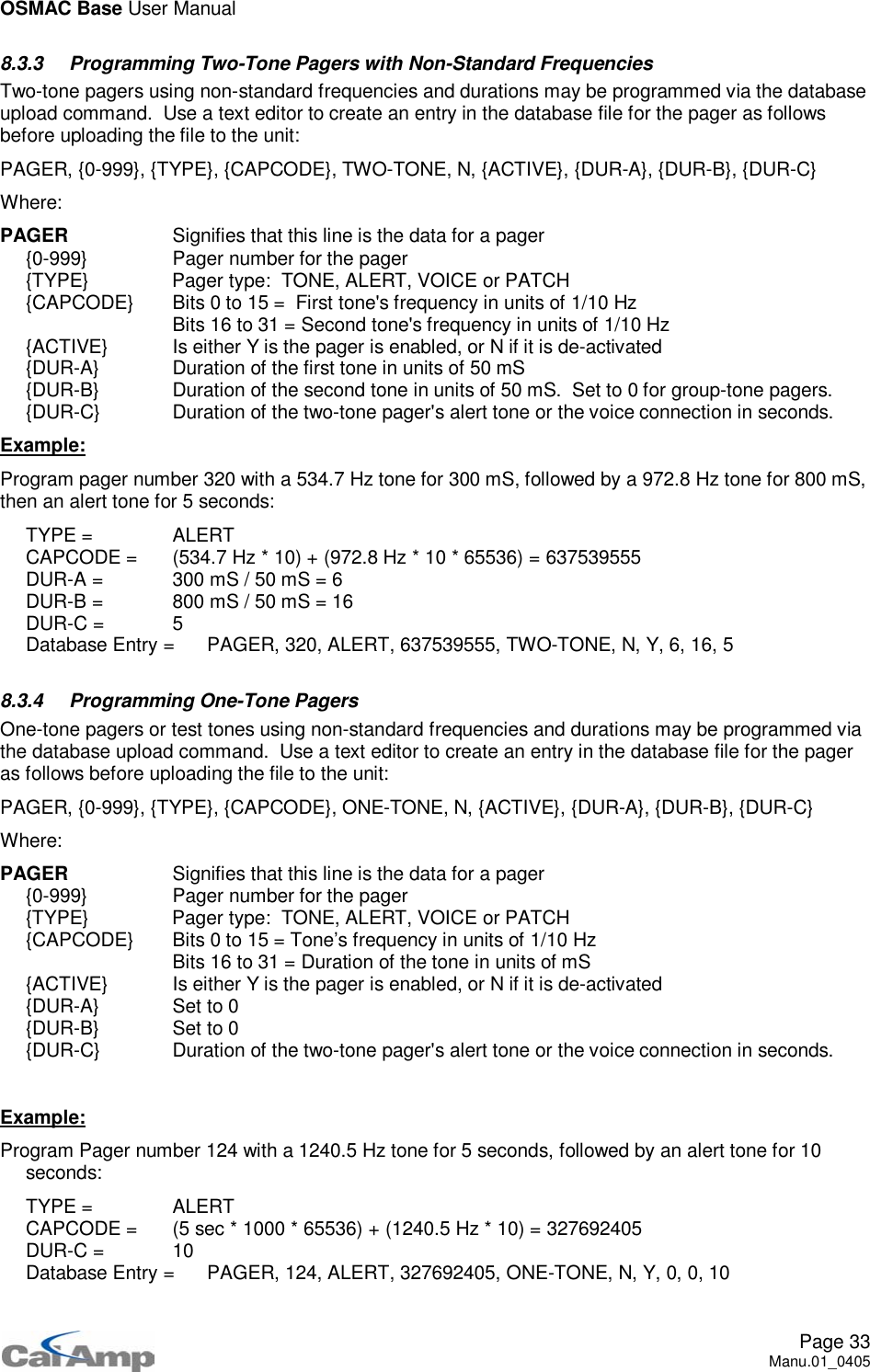
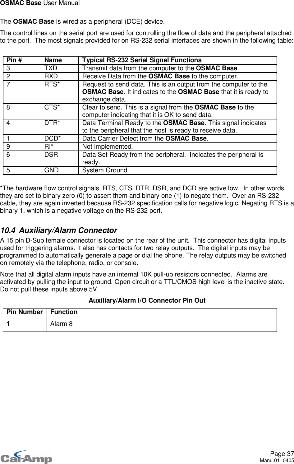
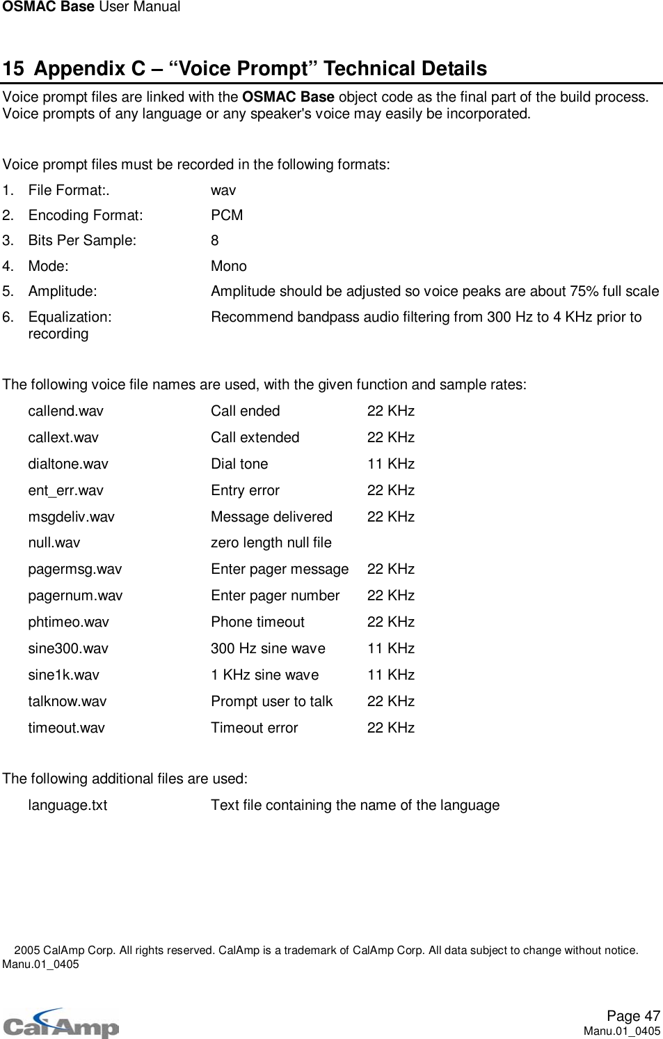
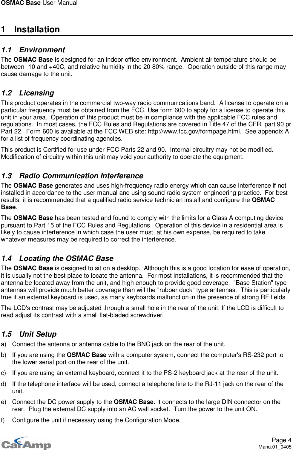
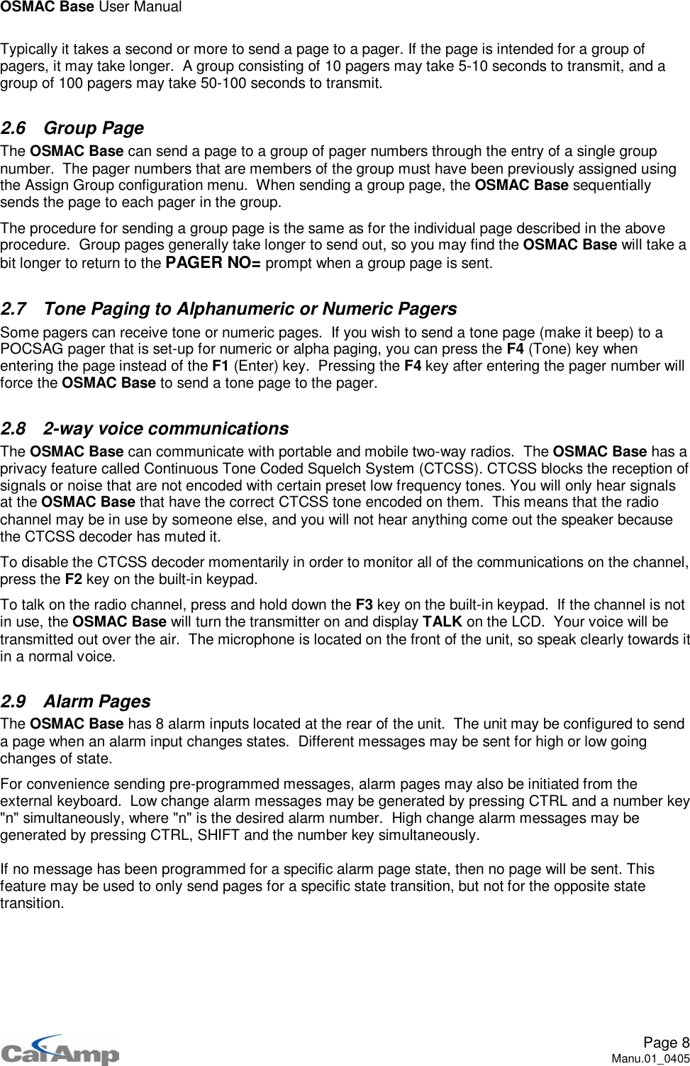
![OSMAC Base User ManualPage 34Manu.01_04058.3.5 Programming the Unit's ConfigurationThe unit configuration data stored in the SERIAL, MODE, RADIO and AUTODIAL entries are normallyignored when the database file is uploaded to the OSMAC Base as a security feature in order toprevent unauthorized users from changing the unit's configuration.If it is desired to change the OSMAC Base's configuration with data downloaded previously from aOSMAC Base unit, use a text editor to add the following line to the database file immediately after the"DB1" entry:PASSWORD,xxxxxx,[0D]Where xxxxxx is the same password required to access the Configuration Mode from the OSMACBase's front panel.Note that the unit's Firmware Version and CW ID String are not changed when uploading the databasefile. These entries in the database file are ignored during the upload process.8.3.6 Keyboard EmulationKey presses from an external keyboard may be simulated from the computer ports for use inautomated test stations or other special applications. As a security feature, the PASSWORDcommand must have been sent prior to using this feature.To simulate key presses from an external keyboard, use a text editor to add the following line to thedatabase file after the PASSWORD line:KEY,nnn,[0D] or KEY,nnn,nnn,nnn, [0D]Where nnn represents the desired keycode represented in decimal ASCII representation. Severalkeycodes may be placed on a line if desired as indicated above. Note that the following specialnumbers are defined:Decimal ASCIICode Function1F1Key2F2Key3F3Key4F4Key5 Dash Key6 Delete Key7DownKey8UpKey31 Enter ConfigurationMode](https://usermanual.wiki/Vytek/PC-UC-2.Users-Manual-1/User-Guide-614496-Page-34.png)