Vytek PC-UC-2 Base Station Irrigation Control Module User Manual 1
Vytek Inc Base Station Irrigation Control Module Users Manual 1
Vytek >
Contents
- 1. Users Manual 1
- 2. Users Manual 2
Users Manual 1

Part number: 132728
OSMAC Base
On-Site Communications System
User Manual
Firmware Version 307D80
CalAmp Corp.
Corporate Headquarters
Products Division:
1401 N. Rice Avenue
Oxnard, CA 93030
Phone: (805) 987-9000
Fax: (805) 987-8359

OSMAC Base User Manual
Page 2
Manu.01_0405
Table of Contents
1 Installation............................................................................................................................ 4
1.1 Environment........................................................................................................................... 4
1.2 Licensing................................................................................................................................ 4
1.3 Radio Communication Interference......................................................................................... 4
1.4 Locating the OSMAC Base .................................................................................................... 4
1.5 Unit Setup.............................................................................................................................. 4
2 Local Operation.................................................................................................................... 5
2.1 Overview................................................................................................................................ 5
2.2 Keypad................................................................................................................................... 6
2.3 External Keyboard.................................................................................................................. 6
2.4 Display................................................................................................................................... 7
2.5 Sending a page...................................................................................................................... 7
2.6 Group Page............................................................................................................................ 8
2.7 Tone Paging to Alphanumeric or Numeric Pagers................................................................... 8
2.8 2-way voice communications.................................................................................................. 8
2.9 Alarm Pages........................................................................................................................... 8
3 Two-way Radio and Telephone Operation .......................................................................... 9
3.1 Sending Pages from the Two-Way Radio ............................................................................... 9
3.2 Placing Telephone Calls from the Two-Way Radio.................................................................. 10
3.3 Autodial Calls......................................................................................................................... 10
3.4 Receiving Telephone Calls at the Two-Way radio................................................................... 11
3.5 Sending Pages using the Telephone Interface........................................................................ 12
4 Unit Setup............................................................................................................................. 13
4.1 Configuration Mode................................................................................................................ 15
5 Program Mode...................................................................................................................... 18
5.1 Assign Pager.......................................................................................................................... 18
5.2 Assigning a Group.................................................................................................................. 19
5.3 Sending Test Pages ............................................................................................................... 21
5.4 Alarm Pages........................................................................................................................... 21
5.5 Phone Autodial Memories....................................................................................................... 22
5.6 Status Display Mode............................................................................................................... 22
6 Diagnostics........................................................................................................................... 23
6.1 Built-in Diagnostics................................................................................................................. 23
6.2 Remote Diagnostics ............................................................................................................... 23
7 Serial Port Protocols............................................................................................................24
7.1 TAP........................................................................................................................................ 24
7.2 TAP Protocol Issues............................................................................................................... 26

OSMAC Base User Manual
Page 3
Manu.01_0405
7.3 Sending Multiple-Line Pages .................................................................................................. 27
7.4 Computing the Checksum ...................................................................................................... 27
7.5 COMP1.................................................................................................................................. 27
7.6 COMP2.................................................................................................................................. 28
7.7 ASCII control characters......................................................................................................... 28
8 Database Transfer................................................................................................................ 29
8.1 Database Format.................................................................................................................... 29
8.2 Retrieving the Database ......................................................................................................... 31
8.3 Restoring/Uploading the Retrieved Database ......................................................................... 32
9 Firmware Updating...............................................................................................................35
10 External Connectors ............................................................................................................36
10.1 External Transceiver............................................................................................................... 36
10.2 Keyboard Connector............................................................................................................... 36
10.3 Serial I/O................................................................................................................................ 36
10.4 PortsAuxiliary/Alarm Connector.............................................................................................. 37
11 Specifications....................................................................................................................... 39
12 Alignment ............................................................................................................................. 41
12.1 Adjustments ........................................................................................................................... 41
12.2 Alignment Procedure.............................................................................................................. 41
13 Appendix A - Frequency Coordinators................................................................................ 43
13.1 For frequencies designated with an "IW" in Section 90.35 of the Commission's rules: ............. 43
13.2 For frequencies designated with an "IP" in Section 90.35 of the Commission's rules: .............. 43
13.3 For frequencies designated with an "LR" in Section 90.35 of the Commission's rules:............. 43
13.4 For all other frequencies, applicants may use any coordinators listed above or one of the
following:........................................................................................................................................ 43
14 Appendix B - Regulatory Compliance Information Statements ......................................... 45
14.1 Federal Communications Commission Part 68 Statements: .................................................... 45
14.2 Industry Canada CS-03 Statements:....................................................................................... 45
15 Appendix C - "Voice Prompt" Technical Details................................................................. 47
Copyright Notice
The OSMAC Base contains copyrighted Software stored in its internal EPROM and FLASH memories. CalAmp
Corp. retains all rights to the Software, including the exclusive right to copy or reproduce in any form the software
in this product. The Software (which includes the data in the EPROM and FLASH memories) may not be copied
without the expressed written consent of CalAmp Corp. Purchasing this product does not grant, either directly or by
implication, the buyer any license to use the Software for any purpose other than for the normal operation of the
purchased product.

OSMAC Base User Manual
Page 4
Manu.01_0405
1 Installation
1.1 Environment
The OSMAC Base is designed for an indoor office environment. Ambient air temperature should be
between -10 and +40C, and relative humidity in the 20-80% range. Operation outside of this range may
cause damage to the unit.
1.2 Licensing
This product operates in the commercial two-way radio communications band. A license to operate on a
particular frequency must be obtained from the FCC. Use form 600 to apply for a license to operate this
unit in your area. Operation of this product must be in compliance with the applicable FCC rules and
regulations. In most cases, the FCC Rules and Regulations are covered in Title 47 of the CFR, part 90 pr
Part 22. Form 600 is available at the FCC WEB site: http://www.fcc.gov/formpage.html. See appendix A
for a list of frequency coordinating agencies.
This product is Certified for use under FCC Parts 22 and 90. Internal circuitry may not be modified.
Modification of circuitry within this unit may void your authority to operate the equipment.
1.3 Radio Communication Interference
The OSMAC Base generates and uses high-frequency radio energy which can cause interference if not
installed in accordance to the user manual and using sound radio system engineering practice. For best
results, it is recommended that a qualified radio service technician install and configure the OSMAC
Base.
The OSMAC Base has been tested and found to comply with the limits for a Class A computing device
pursuant to Part 15 of the FCC Rules and Regulations. Operation of this device in a residential area is
likely to cause interference in which case the user must, at his own expense, be required to take
whatever measures may be required to correct the interference.
1.4 Locating the OSMAC Base
The OSMAC Base is designed to sit on a desktop. Although this is a good location for ease of operation,
it is usually not the best place to locate the antenna. For most installations, it is recommended that the
antenna be located away from the unit, and high enough to provide good coverage. "Base Station" type
antennas will provide much better coverage than will the "rubber duck" type antennas. This is particularly
true if an external keyboard is used, as many keyboards malfunction in the presence of strong RF fields.
The LCD's contrast may be adjusted through a small hole in the rear of the unit. If the LCD is difficult to
read adjust its contrast with a small flat-bladed screwdriver.
1.5 Unit Setup
a) Connect the antenna or antenna cable to the BNC jack on the rear of the unit.
b) If you are using the OSMAC Base with a computer system, connect the computer's RS-232 port to
the lower serial port on the rear of the unit.
c) If you are using an external keyboard, connect it to the PS-2 keyboard jack at the rear of the unit.
d) If the telephone interface will be used, connect a telephone line to the RJ-11 jack on the rear of the
unit.
e) Connect the DC power supply to the OSMAC Base. It connects to the large DIN connector on the
rear. Plug the external DC supply into an AC wall socket. Turn the power to the unit ON.
f) Configure the unit if necessary using the Configuration Mode.

OSMAC Base User Manual
Page 5
Manu.01_0405
2 Local Operation
2.1 Overview
The OSMAC Base is a desk top system that provides paging and wireless two-way communications.
With an Intel 32 bit processor at its core, and 4 megabytes of FLASH memory, the OSMAC Base can
handle the wireless communications needs of the small office or a large plant.
OSMAC Base features:
ÖStand-alone operation with built-in keypad and LCD display.
ÖTwo built-in RS-232 serial ports for advanced paging applications.
ÖBuilt-in telephone interface for remote access.
ÖInternal two-way radio for monitoring the channel and two-way voice communication.
ÖPOCSAG paging encoder at 512, 1200, and 2400 baud
ÖOptional two-tone and group-tone paging
Ö1000 pager database
ÖGroup paging
Ö8 external alarm inputs for automatic generation of pre-programmed pages.
ÖPages may be initiated from DTMF equipped two-way radios.
ÖBuilt-in speaker and microphone, with provisions for external connections.
ÖMay optionally be programmed and operated using an external keyboard
The OSMAC Base operates in one of two basic modes. They are the Page Mode and the Program
Mode.ThePage Mode is used to send digital pages to a selected pager or group of pagers. It may also
be used to communicate with a two-way radio. For the OSMAC Base to send pages to a pager, it must
first be programmed with the pager's CAP code. This is done once, using the Program Mode. The
Program Mode is used to set up the individual pager's information, group information, automatic paging
information, and some system-level features.
Although the operator may send pages using the built-in keypad or an external keyboard, pages may also
be generated in a variety of other ways. Pages may be initiated through the two RS-232 serial ports on
the rear of the unit. Another way is to use the built-in telephone interface. When connected to a
telephone line, pages may be entered using a touch-tone phone by dialing into the unit. The OSMAC
Base may also be configured to automatically generate a page, based upon an electrical input to special
input pins on the rear of the unit.
The OSMAC Base is one of the most versatile paging devices on the market today!
The OSMAC Base has an internal database, which stores the CAP code for every pager in your system.
The CAP code is the special 7 digit code that identifies an individual pager or paging receiver device. To
make paging simpler, you need only configure the CAP codes once by assigning it an easy-to-remember
number. For instance, you may have 3 pagers with the following CAP codes: 1924589, 0029111,
0935199. You can program them into the database as pager numbers 1, 2, and 3 as follows:
Pager CAP Code Pager Number
1924589 1
0029111 2
0935199 3
Now, when it comes time to page pager 2, you will only have to enter the digit 2, rather that the whole
CAP code. Other parameters that must be entered into the database for each pager are the pager type
(tone, numeric, alpha-numeric), baud rate (512, 1200, 2400) active or inactive status, and which groups it
belongs to (if any).

OSMAC Base User Manual
Page 6
Manu.01_0405
To facilitate sending pages to a large number of different pagers, groups of pagers may be set up in the
OSMAC Base. A group is first assigned a number, and the members of the group are programmed into
the group pager database. Once a group is set up, a page may be sent to all the members of the group
simply by sending the page to the given group.
2.2 Keypad
The built-in keypad is used to program the unit, and to manually enter pages. Its keys have the following
functions:
Key Primary Use Secondary Use
0 thru 9 Entering numbers Selecting a sub-menu
F1 Send a page after it is entered Select options from
the sub-menus
F2 Monitor the channel Back up to previous
menu item
F3 Talk to a two-way radio Monitor the channel if
it is busy
F4 Send a tone-only page to a numeric
or alphanumeric pager
DEL Correct an incorrect entry
-
(Program) Used as a dash (-) when entering a
message. Enters the
programming mode
and exits menus
Up/down arrows scroll through
various options on the display.
VOL+/- Adjust the local speaker volume
The OSMAC Base has a keypad buffer that allows a user to type faster than the prompts on the display
come up. Keystrokes will not be lost, and efficient data entry is possible by operators skilled in the
operation of the OSMAC Base.
2.3 External Keyboard
An external keyboard with a PS-2 connector may optionally be used if desired. When the external
keyboard is connected, the unit's built-in keypad continues to operate normally. The external keyboard's
keys function the same way as do the unit's keypad in most cases. Additional features are:
The alphabetic keys may be used when entering pages to alphanumeric pagers.
The ESC key is mapped to the keypad's "-" key.
The ENTER key is mapped to the keypad's F1 key.
The NUM LOCK key is enabled by default, permitting the operator to use the keyboard's numeric
keypad for more efficient entry of numeric data. Note that the keypad's "." key is mapped to the DEL
key.
Pressing CTRL and the Windows "MENU" key simultaneously, or pressing the ALT and TAB keys
simultaneously enters the Setup Mode.
Only keyboards which are FULLY compliant with the standard keyboard communication protocol will work
properly with the OSMAC Base . It has been found that some keyboards do not properly implement the
"retry" protocol and therefore do not work well when the OSMAC Base is busy processing pages from
several sources. If an external keyboard does not work properly with the OSMAC Base ,tryusing
another brand of keyboard.

OSMAC Base User Manual
Page 7
Manu.01_0405
IMPORTANT NOTE: Some keyboards are extremely sensitive to the high RF fields present when an
antenna is connected directly to the rear of the OSMAC Base . The keyboard may stop functioning
properly after the OSMAC Base transmitter is turned on. If this situation occurs, it is recommended that
the antenna be mounted at least several feet from the OSMAC Base or that a different brand of keyboard
be used.
2.4 Display
There is a two-line, twenty-character LCD display on the OSMAC Base. The three LEDs on the top right
side of the unit indicate the state of the transmitter, whether the channel is busy, and the programming
mode.
2.5 Sending a page
The OSMAC Base is ready to send a page when the LCD display shows:
This means the OSMAC Base is waiting for you to enter the pager number to which you which to send a
page. Using the keypad or an external keyboard, enter the number (not the CAP code) of the pager you
wish to page. Once you enter the pager number, press the F1 key. There are three standard types of
pagers supported by the OSMAC Base. They are: tone-only, numeric and alpha-numeric. An option is
available which supports two-tone pagers as well. Depending upon what type of pager you are sending
the page to, one of the following sequences will take place:
1. POCSAG tone-only pagers
If the pager is a tone-only type, it does not have a display. A page sent to it will cause it to beep.
When a page is sent to it, the display will show TONE PAGER while it is sending the page over-the-
air to the pager. This will take about one second, after which it will display PAGE ACCEPTED for a
couple seconds, and then return back to the PAGER NO= prompt.
2. Numeric and alpha-numeric pagers
If the pager is designated as a Numeric pager or an Alphanumeric pager in the OSMAC Base
database, then the LCD display will show NUMERIC PAGER or ALPHA PAGER for one second, and
then the LCD display will show ENTER MESSAGE. The user enters the message using the keypad
into line 2 of the display. If the message is longer than the length of the display, the display will
automatically scroll down to the next line as the message is entered. Pressing the DEL key deletes
the previous character entered. Once the data is entered, press the F1 key to send the page. The
display will show PAGE ACCEPTED for a couple seconds and then the display will return back to the
PAGER NO= prompt.
Note that:
Only messages with numbers may be sent when using the built-in keypad.
Alphanumeric messages may be sent to alphanumeric pagers when using an external keyboard
or the computer interface.
The POCSAG characters "[", "]", "-", "space" and "U" may be sent to numeric pagers when using
the external keyboard, mobile radio or the computer interface.
3. Two-tone pagers
Two-tone pagers accept a sequence of two tones. The CAPCODE is a number between 0 and 999.
A large number of standard tone plans are supported by the OSMAC Base. Pagers with non-
standard tone frequencies may be programmed via the database upload command. After the paging
tones are sent, an alert sound or a voice message from the telephone interface or console may
optionally be sent to the pager. Alternatively, the phone patch may be initiated.
PAGER NO =

OSMAC Base User Manual
Page 8
Manu.01_0405
Typically it takes a second or more to send a page to a pager. If the page is intended for a group of
pagers, it may take longer. A group consisting of 10 pagers may take 5-10 seconds to transmit, and a
group of 100 pagers may take 50-100 seconds to transmit.
2.6 Group Page
The OSMAC Base can send a page to a group of pager numbers through the entry of a single group
number. The pager numbers that are members of the group must have been previously assigned using
the Assign Group configuration menu. When sending a group page, the OSMAC Base sequentially
sends the page to each pager in the group.
The procedure for sending a group page is the same as for the individual page described in the above
procedure. Group pages generally take longer to send out, so you may find the OSMAC Base will take a
bit longer to return to the PAGER NO= prompt when a group page is sent.
2.7 Tone Paging to Alphanumeric or Numeric Pagers
Some pagers can receive tone or numeric pages. If you wish to send a tone page (make it beep) to a
POCSAG pager that is set-up for numeric or alpha paging, you can press the F4 (Tone) key when
entering the page instead of the F1 (Enter) key. Pressing the F4 key after entering the pager number will
force the OSMAC Base to send a tone page to the pager.
2.8 2-way voice communications
The OSMAC Base can communicate with portable and mobile two-way radios. The OSMAC Base has a
privacy feature called Continuous Tone Coded Squelch System (CTCSS). CTCSS blocks the reception of
signals or noise that are not encoded with certain preset low frequency tones. You will only hear signals
at the OSMAC Base that have the correct CTCSS tone encoded on them. This means that the radio
channel may be in use by someone else, and you will not hear anything come out the speaker because
the CTCSS decoder has muted it.
To disable the CTCSS decoder momentarily in order to monitor all of the communications on the channel,
press the F2 key on the built-in keypad.
To talk on the radio channel, press and hold down the F3 key on the built-in keypad. If the channel is not
in use, the OSMAC Base will turn the transmitter on and display TALK on the LCD. Your voice will be
transmitted out over the air. The microphone is located on the front of the unit, so speak clearly towards it
in a normal voice.
2.9 Alarm Pages
The OSMAC Base has 8 alarm inputs located at the rear of the unit. The unit may be configured to send
a page when an alarm input changes states. Different messages may be sent for high or low going
changes of state.
For convenience sending pre-programmed messages, alarm pages may also be initiated from the
external keyboard. Low change alarm messages may be generated by pressing CTRL and a number key
"n" simultaneously, where "n" is the desired alarm number. High change alarm messages may be
generated by pressing CTRL, SHIFT and the number key simultaneously.
If no message has been programmed for a specific alarm page state, then no page will be sent. This
feature may be used to only send pages for a specific state transition, but not for the opposite state
transition.

OSMAC Base User Manual
Page 9
Manu.01_0405
3 Two-way Radio and Telephone Operation
The OSMAC Base has a built-in radio transceiver enabling it to communicate with other two-way radios
and to receive over-the-air commands to generate pages, connect to the telephone system, dial phone
numbers and answer incoming telephone calls. The telephone interface may be utilized for generating
pages or initiating phone patches with two-way-radios.
To remotely control the OSMAC Base with a two-way radio or from a telephone, the two-way radio or
telephone must be equipped with a DTMF encoder. All commands sent to the OSMAC Base are entered
via the DTMF keypad, and in most cases, the commands are similar to the ones used locally on the
OSMAC Base's built-in keypad. During two-way radio operations, the OSMAC Base will not transmit
pages. Any pages entered by the front panel, external keyboard or computer ports will be queued and
send later, when the radio is idle.
3.1 Sending Pages from the Two-Way Radio
This section describes how to send a page with the OSMAC Base using a DTMF keypad-equipped two-
way radio. The OSMAC Base and the two-way radio must have previously been configured to
communicate on the same channel, and utilize the same CTCSS tones.
To send a page to a pager from the two-way radio, you must:
1. Send *9 to alert the OSMAC Base that you intend to send a page.
2. If desired, optionally listen to the receiver for the "Enter Pager Number" prompt, which is a sequence
of three beeps. A series of alternating high and low beeps indicates an error in the command
sequence or a timeout occurred. If voice prompts have been enabled, then a voice message will be
heard instead of the beeps.
3. Enter the digits of the pager number you wish to page. If the pager's number is less than three digits
in length, then press the *key to terminate the pager's number. Note that the *key is not used to
terminate three digit pager numbers.
4. If desired, optionally listen to the receiver for a low / high beep sequence, which signifies that the
pager number was accepted. A series of alternating high and low beeps indicates an error in the
pager number or a timeout occurred. If voice prompts have been enabled, then a voice message will
be heard instead of the beeps.
5. Enter the numeric digits you wish to send to the pager. Do not enter any digits if you only wish to
"beep" the pager. Note that the following DTMF keys have special meanings:
DTMF Key Pager Character Comments
* - Hyphen character
# {none} Send the page
A Space character
B ] Right bracket
C [ Left bracket
D U Urgency indicator
6. Press the #key to send the page.
To send a new message to the same pager again, you may:
1. Type *0 to alert the OSMAC Base that you intend to send a page to the same pager number as
before.
2. Continue from step 4 of the instructions above to input the new message to be sent.

OSMAC Base User Manual
Page 10
Manu.01_0405
3.2 Placing Telephone Calls from the Two-Way Radio
Two-way radios can place "autopatch" telephone calls through the OSMAC Base to a telephone line
connected to the rear of the OSMAC Base.
The OSMAC Base operates in a simplex mode. In other words, it can only receive or transmit at any
given time, and not both simultaneously. If it is transmitting, it cannot receive, and when it is receiving, it
cannot transmit. Because of this, there are a number of things to keep in mind when making or receiving
a telephone call through the OSMAC Base. One is that the two-way radio user will hear an occasional
ticking sound. This is the OSMAC Base periodically checking for transmissions from the two-way radio.
The other is that users must learn to wait about a second before talking whenever the OSMAC Base
switches between transmit and receive modes.
The OSMAC Base uses a Voice Operated Switch (VOX) circuit on the telephone line. VOX circuit
switches the OSMAC Base from transmit mode to receive mode when it detects that the audio coming in
from the telephone line has stopped.
To place a telephone call:
1. Press the *7keys on the two-way radio's DTMF keypad. This tells the OSMAC Base that you wish
to place a telephone call.
2. Optionally listen for the confirmation beeps to come back from the OSMAC Base. If autopatch
operation has been disabled from the Configuration Menu, then alternating high and low beeps will
signal an error. If voice prompts have been enabled, then a dial tone will be heard instead of the
beeps.
3. Begin dialing the telephone number you wish to call after the dial tone ends. At the end of the
telephone number, you may enter a *to dial the phone number. Alternatively, the phone number will
be dialed if no keys are pressed after a few seconds. The DTMF tones being sent to the phone line
will be heard to confirm dialing.
4. Once the called party answers, the phone VOX circuit takes over. When the called party speaks, the
OSMAC Base transmits his or her voice.
5. The mobile user will hear a periodic ticking sound as the OSMAC Base briefly switches to receive
mode to determine whether the mobile user wishes to interrupt the conversation and has begun
transmitting.
6. If neither party is talking, a single beep will be heard periodically to remind the mobile user that the
phone patch is still in operation.
7. A timeout timer exists in order to shut down the phone patch automatically in the event that the
mobile user goes out of range or has a battery outage. Warning beeps or a voice message will be
sent 30 seconds before the timeout timer expires and the phone call is terminated. The mobile or
phone user may press *in order to reset the timeout timer and continue the phone call.
8. End the conversation from the two-way radio or the phone by pressing the #key. A high, then low
beep sequence or a voice message should be heard to confirm the disconnection.
3.3 Autodial Calls
The OSMAC Base has 10 "auto-dial" memories containing telephone numbers that can be automatically
dialed. See the Programming section for information on how to program these numbers.
In order to make an Autodial call from a two-way radio:
1. Press the *6 keys on the two-way radio's DTMF keypad, followed by the number of Autodial
memory you wish to place the call to. Memory number 0 will be used if no number is sent after the *6
command.
2. Operation continues from step 4 as described above.

OSMAC Base User Manual
Page 11
Manu.01_0405
3.4 Receiving Telephone Calls at the Two-Way radio
The OSMAC Base can also be used to route telephone calls from the telephone line to two-way-radios.
To initiate a phone call from the telephone interface:
1. Dial the phone number of the telephone line connected to the OSMAC Base.
2. The will display "Phone Ringing" when the ring signal is detected and wait for the number of rings
programmed in the Configuration Menu.
3. The OSMAC Base will answer the phone in a manner determined by the settings of the "Remote
Paging" and "Call Forwarding" modes as set in the Configuration Menu. The display will read "Phone
in Use."
Remote
Paging Call
Forwarding OSMAC Base Operation When Called
Enabled Enabled Phone answered with a "Enter Pager Number"
prompt.
User may press * 5 to request a phone patch and
send "ringing" tones to the two-way-radio users.
User may enter the number of a pager to be paged
and a numeric message.
Enabled Disabled Phone answered with a "Enter Pager Number"
prompt.
"Error" tones are generated if the user presses * 5 .
User may enter the number of a pager to be paged
and a numeric message.
Disabled Enabled Phone answered with "ringing" tones which are
also sent to the two-way-radio users to request a
phone patch.
Disabled Disabled The phone line is not answered
4. The telephone user must enter *5 to request a "reverse autopatch" phone call if "Remote Paging"
is enabled.
5. If "Call Forwarding" is enabled and the telephone line rings, the OSMAC Base will transmit a
simulated ring signal over the air. To answer the call, a mobile user must press the *key to take the
telephone line off-hook. To hangup the call, either the phone or mobile user must press the #key.
6. Once the called party answers, the phone VOX circuit takes over. When the phone user speaks, the
OSMAC Base transmits his or her voice.
7. The mobile user will hear a periodic ticking sound as the OSMAC Base briefly switches to receive
mode to determine whether the mobile user wishes to interrupt the conversation and has begun
transmitting.
8. If neither party is talking, a single beep will be heard periodically to remind the mobile user that the
phone patch is still in operation.
9. A timeout timer exists in order to shut down the phone patch automatically in the event that the
mobile user goes out of range or has a battery outage. The length of the timer is set in the
Configuration Menu. Warning beeps or a voice message will be sent a few seconds before the
timeout timer expires and the phone call is terminated. The mobile user or phone user must press *
to reset the timeout timer and continue the phone call.
10. End the conversation from the two-way radio or phone by pressing the #key. A high, then low beep
sequence or a voice message should be heard to confirm the disconnect.

OSMAC Base User Manual
Page 12
Manu.01_0405
3.5 Sending Pages using the Telephone Interface
This section describes how to send a page with the OSMAC Base using a DTMF keypad-equipped
telephone. Note that the phone will not be answered until any "radio paging" command sequence in
progress is completed.
To send a page to a pager from the telephone interface, you must:
1. Dial the phone number of the telephone line connected to the OSMAC Base.
2. If the "Remote Paging" mode has been enabled from the Configuration Menu, the OSMAC Base will
answer the phone and send an "Enter Pager Number" prompt, which is a sequence of three beeps. If
voice prompts have been enabled, then a voice message will be heard instead of the beeps.
3. Enter the digits of the pager number you wish to page. If the pager's number is less than three digits
in length, then press the *key to terminate the pager's number. Note that the *key is not used to
terminate three digit pager numbers.
4. If desired, optionally pause sending beeps and listen for a low / high tone sequence, which signifies
that the pager number was accepted. A series of alternating high and low beeps indicates an error in
the pager number or a timeout occurred. If voice prompts have been enabled, then a voice message
will be heard instead of the beeps.
5. Enter the numeric digits you wish to send to the pager. Do not enter any digits if you only wish to
"beep" the pager.
6. Press the #key to send the page. You will hear a series of beeps increasing in pitch or a voice
message to indicate that the page was sent.
7. If a two tone pager with the "TONE+VOICE" function enabled has been paged, a voice prompt will be
given instructing the caller to speak a voice message. If a two-tone pager with the "TONE+PATCH"
function enabled has been paged, the phone patch will be connected automatically.
8. If the caller hesitates sending DTMF tones for a number of seconds, a series of alternating high and
low beeps or a voice message will be sent, indicating that a timeout occurred.
9. The OSMAC Base will then hang-up the phone line.

OSMAC Base User Manual
Page 13
Manu.01_0405
4UnitSetup
The OSMAC Base supports numerous functions and operating modes. These are programmed via a
series of menus. The following table lists configuration parameters and menus within the OSMAC Base
unit that the user may wish to modify. Operating parameters are stored in non-volatile memory, and will
not need to be reconfigured during the life of the product unless the user wishes to change them. The
default settings are shown in BOLD.
OSMAC BASE COMMAND MENU STRUCTURE
System Configuration
(Key 1held down during power-up, or CTRL-MENU or ALT-TAB from an external keyboard)
PASSWORD = Contact Distributor
1 SERIAL PORT #1
1 SERIAL DATA BITS
7DATABITS
8DATABITS
2 SERIAL PORT RATE
1-300BAUD
2-600BAUD
3 - 1200 BAUD
4 - 2400 BAUD
5 - 4800 BAUD
6 - 9600 BAUD
7 - 19200 BAUD
3 SERIAL STOP BITS
1STOPBIT
2STOPBITS
4 SERIAL PARITY
EVEN PARITY
ODD PARITY
NO PARITY
5 FLOW CONTROL
NO FLOW CONTROL
HARDWARE CONTROL
6 SERIAL PROTOCOL
1TAP
2COMP1
3COMP2
7TAPTIMEOUT
{30 Seconds default}
8COMPTIMEOUT
{60 Seconds default}
9 MANUAL TIMEOUT
{90 Seconds default}
2 SERIAL PORT #2
1 SERIAL DATA BITS
7DATABITS
8DATABITS
2 SERIAL PORT RATE
1-300BAUD
2-600BAUD
3 - 1200 BAUD
4 - 2400 BAUD
5 - 4800 BAUD
6 - 9600 BAUD
7 - 19200 BAUD
3 SERIAL STOP BITS
1STOPBIT
2STOPBITS
4 SERIAL PARITY
EVEN PARITY
ODD PARITY
NO PARITY
5 FLOW CONTROL
NO FLOW CONTROL
HARDWARE CONTROL
6 SERIAL PROTOCOL
1TAP
2COMP1
3COMP2
7TAPTIMEOUT
{30 Seconds default}
8COMPTIMEOUT
{60 Seconds default}
9 MANUAL TIMEOUT
{90 Seconds default}
3 MODE SELECTION
1 SPEAKER ENABLE
ENABLE
DISABLE
2 BUSY CH LOCKOUT
ENABLE
DISABLE
3 REMOTE PAGING
ENABLE
DISABLE
4 CALL FORWARDING
ENABLE
DISABLE
5 AUTOPATCH TIMER
0 = PATCH DISABLED
DEFAULT = 10 MINUTES
6 VOICE PROMPTS
ENABLE
DISABLE
7WARMUPSIGNAL
ENABLE
DISABLE
8 RINGS TO ANSWER
0= ANSWER IMMEDIATELY
1= DEFAULT
9 NUMBER DONE DELAY
{5 Seconds default}
4 TRANSCEIVER
1 TX SETUP
1TXFREQUENCY
{464.5MHz}
2 TX SIGNALING
1 (CARRIER ONLY)
2CTCSS
3 TX BANDWIDTH
NARROW BAND
WIDE BAND
4 TX DATA DELAY (MS)
{20mSdefault}
5 TX STREAM DELAY
{600mS
default}
2 RX SETUP
1RXFREQUENCY
{464.5MHz}
2 RX SIGNALING
1 (CARRIER ONLY)
2CTCSS
3 SHIFT CPU CLOCK?
DISABLED
ENABLED
3 INVERT CARRIER DETECT
YES
NO
4 INVERT TRANSMIT DATA
YES
NO
5TXTYPE
NO TYPE SELECTED
VHF (MODEL 204)
UHF
VHF (MODEL 3464)
UHF (MODEL 3412-X)
6 TX/RX SWITCH TIME (MS)
DEFAULT = 50 MS
5CWCALLSIGN
{DEFAULT = NONE}
6 DIAGNOSTICS MODE
{See below for details}

OSMAC Base User Manual
Page 14
Manu.01_0405
Reset FLASH Memory
(Key 8held down during power up)
RESET FLASH?
PASSWORD = 42983
RESET FLASH?
NO
YES
Program Mode
(Key "-" held down during normal operation)
PASSWORD = 7531
1 ASSIGN PAGER
PAGER NO =
ACTIVE?
YES
NO
TYPE =
POCSAG 512
POCSAG 1200
POCSAG 2400
TWO TONE
FUNC =
TONE
NUMERIC
ALPHA
TONE ONLY
TONE+ALERT
TONE+VOICE
TONE+PATCH
ALERT OR VOICE DURATION
{0 TO 31 SEC}
0=1/2SECOND
SELECT TONE GROUP
CAPCODE =
DIAGONAL TONE SELECT
FIRST TONE
SECOND TONE
GROUP TONE
SAVE CHANGES?
YES
NO
2 ASSIGN GROUP
SELECT GROUP
ASSIGN PAGER NUMBER
SELECT GROUP FUNC
TONE
NUMERIC
ALPHA
ENTER MEMBER NUMBER
ENTER PAGER NUMBER
3 TEST PAGE
PAGING PAGER 0
4 ALARM PAGES
ALARM NUMBER =
ALARM x PAGER
ALARM LOW MESSAGE
ALARM HIGH MESSAGE
5 AUTODIAL MEMORY
AUTODIAL MEMORY =
ENTER PHONE NUMBER
{DEFAULT = NONE}
Diagnostics Mode
(Menu item 6 from the System Configuration Mode)
F1 TOGGLE PHONE CONNECTION
DISCONNECTED
CONNECTED
F2 TOGGLE RADIO CONNECTION
DISCONNECTED
RECEIVE MODE
TRANSMIT MODE
F3 CONNECT MICROPHONE
DISCONNECTED
CONNECTED
F4 TOGGLE SPEAKER CONNECTION
DISCONNECTED
CONNECTED
1 PAGER BIT TEST
512 BAUD
1200 BAUD
2400 BAUD
2 SOUND TESTS
{Press number, function or arrow
keys}
3 DTMF TESTS
(UP ARROW key selects modes)
ENCODER TEST MODE
DECODER TEST MODE
ENCODER BEEP MODE
ENCODER LOW TONE
ENCODER HIGH TONE
4 DAC RAMP TEST
5 LCD TESTS
6 KEYPAD & KEYBOARD TESTS
7ALARMINPUTS
8 FIRMWARE VER

OSMAC Base User Manual
Page 15
Manu.01_0405
4.1 Configuration Mode
The System Configuration Mode is entered by holding the 1 key down on the front panel while the
power is turned on, by pressing the CTRL and MENU keys, or by pressing the ALT and TAB keys
simultaneously from the external keyboard. The OSMAC Base will prompt the user for a password
before entering the configuration programming mode. Press the arrow keys to cycle through the
configuration parameters. The Menu number in the table above lists the location within the OSMAC
Base programming menus that the particular parameters may be found.
To change any of the parameters that require a numeric entry, press the number key to enter the value
and then press the F1 key. In the case of values that will scroll, press any number key to scroll through
the available selections. Press the -key to exit from sub-menus to the upper level menus.
To exit the configuration mode, press the -key. Note that values are not permanently stored until the
Configuration Mode is exited by pressing the -key. If the unit is turned off, or power is lost before the -
key is entered, changes to the configuration are not stored.
4.1.1 Serial Port Setup
Each of the two serial ports may be configured independently. The table above lists the parameters
that may be programmed. The serial ports are located at the rear of the unit and are labeled PORT 1
and PORT 2.
Timeout parameters for the various protocols are given in seconds. Set the timeout to 0 if no timeout
is desired.
4.1.2 Speaker Enable
If this mode is disabled, then the speaker is muted at all times except in the Diagnostics Mode. This
maybeusediftheOSMAC Base is in a location where sounds from the speaker are not desirable.
4.1.3 Busy Channel Lockout
If this mode is enabled, then the OSMAC Base will not transmit if the channel is busy. This may be
desirable in order to avoid interfering with other users on the channel. This mode should be disabled if
there is so much activity on the channel that the pages are not sent out in a timely manner.
4.1.4 Remote Paging
If this mode is enabled, then remote users are permitted to call the OSMAC Base via a telephone line
and to generate pages to be transmitted.
4.1.5 Call Forwarding
If this mode is enabled, then remote users are permitted to call the OSMAC Base via a telephone line
and to request a phone autopatch with two-way-radio users.
4.1.6 Autopatch Timer
The autopatch timer establishes the length of time the OSMAC Base waits before hanging up the
autopatch automatically. This is needed in case the two-way-radio user's batteries fail or he goes out
of range.
Enter the number of minutes the autopatch may be operated before the disconnect warning tones are
sent. The DEL key may be used to delete digits. Press the "-" key to exit the menu. Note that
autopatch operation may be disabled by setting the Autopatch Timer value to 0.

OSMAC Base User Manual
Page 16
Manu.01_0405
4.1.7 Voice Prompts
This mode selects whether beeps or voice prompts are used to confirm radio and phone operations
with the OSMAC Base. The language of the voice prompts is determined by which firmware file has
been loaded. If you are interested in a language other than English, contact your distributor for
availability.
4.1.8 Warmup Signal
If this mode is enabled, then a special "warmup" signal is transmitted for a brief period of time at the
beginning of each page. This is required for more reliable operation by some pagers.
4.1.9 Rings to Answer
The phone will be answered after the number of rings specified. Enter 0 to answer the phone
immediately after detection of a phone ring.
4.1.10 Number Done Delay
When entering a phone number to be dialed in the autopatch mode, this programmable parameter
determines how long the unit will wait after each digit is pressed until assuming that all digits have
been entered. After this delay, the phone number will automatically be dialed. Users not wishing to
wait for this timeout may alternatively press the # key to terminate the phone number and tell he unit to
dial the phone number immediately.
4.1.11 Transceiver Setup
The OSMAC Base either contains a two-way transceiver or works with an external transceiver. In
either case, the factory has programmed the correct Transmitter Type, Carrier Detect inversion,
Transmit Data inversion, and the TX Bandwidth. The user should not change these settings or
improper operation will result.
4.1.12 TX/RX Switch Time
This parameter is used by the autopatch to determine the sampling time to listen for the mobile radio
user when transmitting the phone user's voice. If it is set too small, the mobile radio user will not be
able to interrupt the transmitter when in the autopatch mode. If it is set too large, then the transmitter's
dropout time will be excessive.
4.1.13 Transmit and Receive Frequencies
Enter the desired transmit or receive operating frequency using the number keys. The decimal point
will automatically be entered. Use the DEL key to delete any correct entries. Press the F1 or "-"key
to accept the new frequency.
4.1.14 Transmit and Receive Signaling
Carrier Squelch operation may be desirable if there are no other users on the channel and there is no
interference. In this mode, the two-way-radio users will be able to hear the paging signals transmitted
by the OSMAC Base. To enable this mode, press 1to select (CARRIER ONLY). Press the "-"keyto
exit the menu.
If there are other users sharing the channel, there is excessive interference, or the two-way-radio
users do not want to hear the paging signals, then CTCSS operation should be used. In this mode, a
low frequency tone is transmitted along with the desired audio. The receiver will only be enabled if this
tone is present at the correct frequency.
To enable this mode, press 2to select CTCSS, then use the arrow keys to select the desired tone
frequency. Press the "-"orF1 key to accept the frequency and exit the entry mode.

OSMAC Base User Manual
Page 17
Manu.01_0405
4.1.15 TX Data Delay
This parameter controls the delay between the time the transmitter is turned on and the start of the
transmit preamble for POCSAG pages. The delay is given in milliseconds.
4.1.16 TX Stream Delay
The TX STREAM DELAY puts small pauses between pages in order to pace the transmission of
discreet pages. This delay helps slower pagers (generally broadband types) to see all the page traffic,
analyze it and recognize those pages addressed to it.
4.1.17 Shift CPU Clock
In rare cases, the desired receive frequency may coincide with computer noise generated by the
internal CPU. This option enables the user to change the CPU's timing, which may shift the CPU's
computer noise away from the desired receive frequency.
4.1.18 CW Identification Call Sign
In many cases, the rules and regulations under which the OSMAC Base is licensed by the
government require that the station's Call Sign be transmitted at regular intervals for identification
purposes using Morse Code. The OSMAC Base sends the Call Sign (with CTCSS turned off so the
mobile radio users won't hear it) every 10 minutes if the Call Sign has been programmed. This feature
is disabled when the unit comes from the factory.
To enable this feature, press 5from the main configuration menu. At the prompt, enter your station's
Call Sign from your license as follows:
Numbers are entered directly from the keypad.
Letters and other special symbols are entered from the keypad by pressing the arrow keys.
Alternatively, an external keyboard may be used to enter alphanumeric characters directly as
typed.
Press the F2 key to accept the displayed letter when using the unit's keypad or to enter a "space"
character which is displayed as a "_" and results in a pause in the Morse Code.
Press the DEL key to delete errors or to disable CW Identification by totally clearing the display.
Press the F1 or "-" key to accept the Call Sign and exit the menu.
Up to 19 characters may be contained in the CW Identification string.

OSMAC Base User Manual
Page 18
Manu.01_0405
5 Program Mode
The Program Mode is used to program CAP codes, add pagers, delete pagers, assign pagers to
groups, configure the alarm pages, and set up various features of the OSMAC Base.Itisalsousedto
toggle a status display on the second line of the LCD on and off.
To enter the programming mode, press the dash "-" key on the keypad or the ESC key on the external
keyboard. The OSMAC Base will prompt you to enter the password. After entering the Program
Mode password (7531) and pressing F1, you can select one of the following menu items:
1 = Assign Pager Assigns pager CAP codes
2 = Assign Group Assigns pagers to groups
3 = Test Page Sends periodic test pages
4 = Alarm Pages Configures alarm triggered pages
5 = autodial memory Configures Autodial memories
- = RETURN TO PAGE Return back to the page mode
When you enter the Program Mode you will see the first selections. Use the UP/DOWN arrows to
scroll through the available options. To exit the Program Mode, press the -(Program) key or the ESC
key. Any changes you make will automatically be saved.
Note: When the OSMAC Base is in the Program Mode, it will revert back to the Page Mode if it is idle
(no keyboard inputs) for two minutes, except that test pages may be sent for an unlimited period of
time.
5.1 Assign Pager
All pagers have an ID code, commonly referred to as a CAP code. It is a long number, difficult to
remember, and may change if a pager is replaced or in for repair. To make paging a pager easy, the
OSMAC Base uses a database stored in its memory to remember every pager's CAP code. Within
the OSMAC Base, every pager is assigned a Pager Number. Because pagers only recognize CAP
codes, the OSMAC Base must translate the pager number into the proper CAP code. The 1 - Assign
Pager menu is used for this function.
1. Begin by entering the Programming Mode as described above, and pressing the number 1key.
The OSMAC Base will respond with:
PAGER No =
F1:OK F2:BACK -:EXIT
Note that the F1 key is used to select an entry, the F2 key goes back to the previous menu item
and the -key exits this mode.
2. Enter the number for the pager you wish to add to the database. For example, to add a pager
number "15" to the database press 1then 5then F1.
3. Next, you will be prompted to activate or deactivate the pager. Press F1 to activate it, or press an
arrow key to switch between Y and N on the display to deactivate it. Press F1 when the correct
response has been chosen.
4. Next, tell the OSMAC Base what type of pager is being assigned. For convenience, the will
display the type of pager previously selected. Press the arrow keys to cycle through the list of
possible pager types. The possible types are: POCSAG 512, POCSAG 1200 and POCSAG 2400.
An option is available which also supports TWO TONE pager types. Note that the OSMAC system
must have all pagers set to 512 baud POCSAG. Once the correct paging format type is in the
display, press the F1 key on the keypad or ENTER on the external keyboard.

OSMAC Base User Manual
Page 19
Manu.01_0405
5. After programming the type, you must program in the function type of the pager being used. The
function type for POCSAG pagers is one of the following:
TONE (pager just beeps)
NUMERIC (pager beeps and displays numbers)
ALPHA (pager beeps and displays numbers and letters.)
The function type for TWO TONE pagers or GROUP TONE pagers is one of the following:
TONE ONLY (send page tones only)
TONE+ALERT (send an alert sound after sending the page tones)
TONE+VOICE (permit phone caller to speak to the pager after sending page tones.)
TONE+PATCH (initiate a phone patch after sending the page tones)
6. Press the arrow keys to cycle through the list of functions. Press the F1 key when the correct
function is displayed.
7. If TONE+ALERT or TONE+VOICE was selected, then you will be asked to specify the duration of
the alert or the voice connection after the paging tones have been sent. You may give a value
between 0 and 31 seconds. Entering 0 will cause an alert tone of 1/2 second or use the default
voice duration of 15 seconds.
8. If a TWO TONE pager has been selected, you will be asked to select the tone plan for the pager.
Use the arrow keys to scroll through the supported plan types. If the tone plan for your pager isn't
listed, then the pager's tone frequencies must be entered using the database upload command.
9. Once a pager number is entered, the OSMAC Base will respond with a prompt asking for the CAP
code for this pager. If the pager number was already in the database, it will display the CAP code
already programmed. If it was not in the database, the CAP code will default to the pager number.
To edit the CAP code, use the DEL key to backspace over it. Press F1 to enter the new CAP
code.
10. If a TWO TONE pager has been selected, you may be asked to specify whether the "diagonal
frequency" is the first or second tone. Alternatively, you may select a "group tone" for the pager.
This will send a single tone to the pager with a pre-determined duration.
11. The OSMAC Base restart back at the PAGER NO = prompt. It will automatically increment to the
next pager number. Press the -to exit the Program Mode when all of the pagers have been
entered into the database. Your entries into the pager database will then be saved in the internal
FLASH memory.
5.2 Assigning a Group
The Group-Page feature is used to send the same page to a number of different pagers. Groups have
numbers just like pagers, and once you define a group and its members, you send pages to the group
just as if it were a single pager. When you assign a number to a group, it is important that the number
is not the same as any individual pager.
There is a limit to the number of pagers that may be assigned to any one group. This is listed in the
Specifications section of the OSMAC Base User Manual.
1. To do the group assignments, select 2-Assign GROUP from the program mode menu. The
display will then show:
GROUP NUMBER =
SELECT GROUP

OSMAC Base User Manual
Page 20
Manu.01_0405
2. Enter the number of the group you wish to work on and then press the F1 key. Valid group
numbers are 1 through 16. The display will then show:
GROUP X PAGER NN
assign pager number
Where X is the group number you wish to work on and NN is the pager number assigned to this
group. Important Note: when you wish to page this group, you will enter the pager number NN
for it, not the group number.
3. Use the DEL key to backspace over NN if you wish to change the pager number this group is
referred to by. If the pager number NN is already assigned to an active pager, the will not allow
you to assign that number to the group and the pager number will be erased. If you wish to use
NN for a group number instead of an individual pager, you must first de-activate the pager. Section
3.1 describes how to deactivate a pager. Once the pager number for this group is set, press the F1
button. The following prompt will appear.
GROUP X = numeric
SELECT GROUP FUNC
4. Using the arrow keys, select the function (numeric, alpha or tone) for this pager group. Members
of the group may be of any type, but this selection will determine the prompt to the user when a
page to this group is initiated. Press F1 when your selection is made. The display will change to:
GROUP X MEMBER NN
ENTER MEMBER NUMBER
5. X will be the group number you are currently working on, and NN will be a number corresponding
to the member number you wish to edit. The first group member you enter will be member 1. The
second one you enter will be member 2 and so on. The display always first shows the next
member number you can enter a new member as. Use the UP/DOWN arrows if you wish to scroll
through the members, or press the DEL key to edit the member number and manually enter the
member number to edit. Press F1 key when you are ready to edit/add the selected group member.
The display will then show:
MEMBER NN =
ENTER PAGER NUMBER
6. Enter the number of the pager you wish to add to the group. For example if you wish to add pager
number 123 to the group, then enter 123 and then press the F1 key. Use the DEL key to
backspace over any entry if you wish to edit it. Note that:
To see the pagers in the database are members of this group, you can use the UP/DOWN
arrow key to scroll through the members of the group.
To delete a member, at the MEMBER NN = prompt, use the DEL key to erase its number from
the screen, and press the F1 key.
7. To finish entering pagers to this group, press the -key.

OSMAC Base User Manual
Page 21
Manu.01_0405
5.3 Sending Test Pages
The test page mode may be used to check the range of the system. With this mode, the OSMAC
Base will automatically generate a page to pager number "0" every ten seconds.
1. Before using this feature, pager number "0" must be programmed as described above.
2. To enable this feature, enter the program mode and press 3. The display will show:
PAGING pAGEr 0
dash (-) to exit
3. Press the - key to return to the programming mode menu.
5.4 Alarm Pages
The OSMAC Base has 8 alarm inputs. These digital inputs are used to generate pre-programmed
pages, each with its own pre-programmed message to any pager, or group of pagers. These may be
used for alarms, but they may also be used to simply generate pre-programmed pages.
If no message has been programmed, then no page will be sent. This facilitates situations in which
messages are only desired for one of the two states.
The inputs may be connected to normally open switches or contacts. When any input is pulled low to
ground, it will generate a pre-programmed page. When any input is pulled high or allowed to "float
high", it will generate a different pre-programmed page.
Alternatively, alarm pages may be initiated from an external keyboard. Hold down the CTRL key and
then press a number key that corresponds to the alarm input number to send the "Alarm Low"
message. Hold down the SHIFT key also to send the "Alarm High" message.
Note that the alarm inputs are not protected from lighting, so the wires must not be run out of doors.
See Section 10.2 for details regarding the wiring of the alarm input connector.
To set up the alarm pages, the user must perform the following steps:
1. Put the unit into the program mode.
2. Press 4to enter the Alarm sub-menu.
3. When the ALARM NUMBER = prompt is shown, enter the alarm number you wish to configure.
Press the F1 key.
4. The OSMAC Base will display AlaRM x PAGER on the top line, and the pager number that will be
paged when the alarm is triggered. Erasing the pager number disables the alarm. Enter the
number of the pager you wish to have paged when the selected alarm input is triggered. Press F1
when done.
5. OSMAC Base will display ALARM low MSG: on the top line of the LCD. On the second line, you
may enter or edit the message to be sent when the alarm input goes low. Press F1 when the
message has been entered.
6. OSMAC Base will display ALARM hi MSG: on the top line of the LCD. On the second line, you
may enter or edit the message to be sent when the alarm input goes high. Press F1 when the
message has been entered.
When entering the alarm messages, the unit's keys operate as follows:
Numeric keys are used to enter numbers
F4 or UP keys select the next letter of the alphabet
F3 or DOWN keys select the previous letter of the alphabet
-key enters a "dash" character
F2 key enters a space character or moves to the next character position to the right
DEL key deletes a character and moves to the next character position to the left
F1 key accepts the entry and exits back to the previous menu.

OSMAC Base User Manual
Page 22
Manu.01_0405
Alphanumeric characters may alternatively be entered directly from an external keyboard
7. Press the F1 key to return to the programming mode menu.
5.5 Phone Autodial Memories
The OSMAC Base has 10 Phone Autodial Memories. These must be programmed prior to use by
two-way-radio users. To program the autodial memories:
1. Enter the number of the autodial memory to be examined. Alternatively press the arrow keys to
cycle through the memories. The first 20 characters of the autodial memory's phone number will
be displayed. Note that each phone number may be up to 27 characters in length.
2. To change the contents of the autodial memory, enter the new phone number using the number
keys on the keypad. The following keys have special functions:
Key Character
Displayed Function
- _ Insert a pause in the dialing sequence
DEL {none} Delete the previous character
F1 {none} Save the phone number and exit the entry
mode
F2 # DTMF # key
F3 * DTMF * key
F4 F Flash hook
3. Press F1 to save the phone number.
4. Repeat steps 1 through 3 as desired, then press the "-" key to exit to the main programming menu.
5.6 Status Display Mode
To toggle the Status Display Mode on and off, press the “-“ key followed by the “F2” key when the unit
is in its idle state. The following status code is displayed on the second line of the LCD, except when
the operator is operating the unit from its keypad. Note that “Phone Ringing” and “Phone in Use”
messages are not displayed when the status display mode is enabled.
RrPpCccQqqTtttDdddddd where: rr = A code indicating the operating state of the
radio
p = A code indicating the operating state of the phone
cc = Codes indicating operating states of the COM ports
qq = Number of pages presently queued for transmission
ttt = Codes indicating states of transmission operations:
- Paging Substate
- Paging State
- Tone and Voice Sequencing
dddddd = Decoded DTMF characters received

OSMAC Base User Manual
Page 23
Manu.01_0405
6 Diagnostics
6.1 Built-in Diagnostics
If the user selects DIAGNOSTICS MODE from the Configuration Menu, the goes into a diagnostics
mode which allows the operator to exercise many of the ’s hardware functions and to help troubleshoot
any problems with connections to the unit. Connections to the phone line, radio, speaker and
microphone may be independently toggled for any desired test configuration.
The Functions that are available are:
F1 - Toggle the connection to the phone line between On and Off
F2 - Toggle the radio connection between Off, Receive and Transmit modes
F3 - Connect the microphone to the transmitter
F4 - Toggle the unit's speaker between On and Off
1 – Pager Bit Test (sends alternating 1010 pattern at a specific baud rate and on/off timing)
1 – 512 baud
2 – 1200 baud
3 – 2400 baud
2 –Sound Tests
– Press any of the number keys or function keys to play one of the first 14 sounds
– Alternatively, press the arrow keys to select sounds
3–DTMFtests
– Press one of the 16 lower buttons to generate DTMF tones in "encode" modes
– Press the "down arrow" key to exit the DTMF test mode
– Press the "up arrow" key to toggle between the following test modes:
- Encode DTMF continuously
- Decode DTMF from the radio or phone line, depending on which was enabled last
- Encode DTMF in 50 mS beeps
- Encode only the low tone continuously
- Encode only the high tone continuously
4 – DAC ramp test (exercises the sound DAC)
– Press number keys to change the ramp frequency
5 – LCD display tests
– Press the - key to sequence between the tests
6 – Keypad and keyboard test
– Keypad codes and external keyboard scan codes are displayed when keys are pressed
– Press the - key on the keypad twice to exit this test mode
7 – Alarms & Ring (displays the status of the alarm inputs and phone ring detection circuitry)
6.2 Remote Diagnostics
Test functions may also be initiated remotely via a two-way radio that is equipped with a 16 tone
DTMF keyboard.
Key
Sequence Function
* A Send an "A" DTMF tone to the radio and the phone line continuously for a period
of time.
* B Send all 16 DTMF tones plus all 8 single tones to the radio and the phone line.
* D Transmit the CW Identification Call Sign in Morse Code. CTCSS is turned on.

OSMAC Base User Manual
Page 24
Manu.01_0405
7 Serial Port Protocols
The OSMAC Base paging transmitter supports three different serial port communication protocols.
Each protocol has its own uses, and the correct one for one application may not be the correct one for
another. The OSMAC Base must be configured to support the desired protocol, and only one protocol
may be used at a time. The three protocols supported are:
TAP (also called IXO) The Telocator Access Protocol is an industry standard protocol for
communications between paging entry devices and a paging terminal.
Individual pagers can be sent individual messages.
COMP1 This protocol is a simple way to send data to one pager. It is designed to
allow a person with a simple computer terminal to type a message into the
OSMAC Base.TheOSMAC Base must be pre-configured with the
CAPCODE of the pager to send the data to, and all data sent into the
serial port of the OSMAC Base will be sent to that one pager.
COMP2 COMP2 is similar to COMP1, except each page requires two lines of text
to be entered. The first line is the pager number to send the page to, and
the second line is the alpha or numeric message to send to that pager.
7.1 TAP
The Telocator Alphanumeric Protocol, or TAP protocol as it is called, is used to send pages to
communicate paging information to a transmitter. It is a sequence of characters sent over a serial
interface to a transmitter. The transmitter must parse the commands, and take the appropriate
actions.
The following sections describe how the TAP protocol works. It assumes that the device
communicating to the OSMAC Base Station is directly connected to it via a serial cable. If other
means are used (i.e. modem) then the modem connection must first be established. For the purposes
of this manual, the OSMAC Base is assumed to be the transmitter, and the device connected to its
serial port is the "Entry Device". Typical entry devices are computers, paging terminals, and alarm
monitors. Characters listed in brackets <xx> are ASCII codes, and the values for them are listed at
the end of this document.
Initiating a Page
Entry Device OSMAC Base Action Comment
<CR> The Entry Device should send a <CR> at two second
intervals until the OSMAC Base responds with the
characters ID=. The <CR> is an ASCII code 13h.
ID=<CR><LF> The OSMAC Base will respond within one second of
the <CR>, and it does not end the ID= prompt with a
<CR> or a <LF>.

OSMAC Base User Manual
Page 25
Manu.01_0405
After initiating a page, and receiving the ID= prompt, the Entry Device can respond in one of two
different ways. One way puts the OSMAC Base into an Automatic Mode, and the other ways puts it
into a Manual Mode.
Automatic Entry of a Page
Entry Device OSMAC Base Action Comment
<ESC>PG1<CR> The Entry Device tells the OSMAC Base
transmitter that it wants to automatically send a
POCSAG page by ending this sequence.
<CR><ACK><CR>
or
<CR><NAK><CR>
or
<ESC><EOT><CR>
The OSMAC Base will respond within one second
of the ACK sequence signifying that the Entry
Device has successfully logged on to the OSMAC
Base. If paging entries cannot be accepted, it will
respond with the NAK sequence or the ETX
sequence, which should force the Entry Device to
disconnect.
<ESC> [p <CR> This "go ahead" sequence tells the Entry Device
that it is OK to go ahead and send over the
information for the first page or pages. The p is
always the lower case "p".
<STX>
PagerID<CR>
Message<CR>
<ETX>
Checksum <CR>
This Pager/Message Sequence Block tells the
OSMAC Base the ID (the Pager Number in the
OSMAC Base's database) of the pager this the
Message is to be sent to. The checksum is
computed as shown later in this document. The
total number of characters sent from the Entry
Device per sequence should not exceed 255.
Repeat the above
Pager/Message
Sequence Block
as many times as
required, if more
pages are to be
sent.
<EOT> <CR> When the Entry Device does not want to send any
more pages, it sends this EOT sequence, to tell
the OSMAC Base that it is finished with this
automatic session.
Pages Accepted <CR>
or
Invalid Page
Entered<CR>
or
<Message><CR>
One of these status messages will be returned at
the end of the session. They are for information
purposes only.
<CR><RS><CR> This is only sent if there was an error in this
session, probably due to an invalid pager ID or a
message type mismatch.
PAGING EXCHANGE
DISCONNECT <CR>
<ESC> <EOT>
The End of Transaction message sent from the
OSMAC Base to the entry device, telling it to
disconnect.

OSMAC Base User Manual
Page 26
Manu.01_0405
Manual Entry of a Page
Entry Device OSMAC Base Action Comment
M<CR> The Entry Device tells the OSMAC Base
transmitter that it wants to manually send a
POCSAG page, by ending the M.
ENTER PAGER NUMBER: The OSMAC Base will respond within one
second of the M sequence signifying that
the Entry Device has successfully logged on
to the OSMAC Base, and it is ready to
receive paging info. The OSMAC Base
begins by responding with this prompt.
PagerID<CR> The user responds with the ID of the pager
he wishes to page.
Enter Alpha Message:
or
Enter Numeric Message:
The OSMAC Base responds with one of the
following messages, depending upon the
type of pager that the PagerID is assigned
to.
Message<CR> The user enters a message to send to the
pager.
Sending Message...<CR> The OSMAC Base displays this message as
it sends the message to the pager.
MessageSent<CR>
or
Can't Deliver to xxxxxxx<CR>
or
Too Slow. Goodby.<CR>
or
Two many errors. Goodby. <CR>
One of these messages will then be sent
from the OSMAC Base, depending upon the
current situation with the page that was
entered. The serial port has a 45 second
activity time, and will force and end to the
manual session if the user does not
complete the page in that time.
7.2 TAP Protocol Issues
7.2.1 Timing
The OSMAC Base will wait for a response to come back from the Entry Device. If a response is not
received before the pre-programmed time-out period, the OSMAC Base will cancel the current
transaction, sending the <ESC> <EOT> <CR> sequence.
7.2.2 Line Feeds
The OSMAC Base will ignore all <LF> characters it receives. The Entry Device may send a <LF> with
any <CR>.
XOFF
In the very unlikely event that the user enters more pages than the OSMAC Base can queue up, the
OSMAC Base will send the <XOFF> character before sending a carriage return. It will send the
<XON> character when buffer space is available for more pages. If the OSMAC Base does not
receive data within 10 seconds after sending an <XON>, it will send another <XON>.

OSMAC Base User Manual
Page 27
Manu.01_0405
7.2.3 EOT
Whenever the OSMAC Base terminates a session by sending the <EOT><CR> sequence, it will drop
the DTR signal on the RS-232 signal for 250mS. This will normally cause any modem connected to it
to disconnect.
7.3 Sending Multiple-Line Pages
If you wish a message to continue on another line of a multi-line pager, you cannot send the <CR>
return into the serial port. Use the TAB character instead of a <CR>. The OSMAC Base will translate
it to a <CR> when it sends the page to the pager.
7.4 Computing the Checksum
The checksum is a simple arithmetic sum of the 7-bit values of all characters preceding it. The
checksum reported is the least significant 12 bits of this summation, converted to BCD ASCII.
Checksum Example:
STX 000 0010
1 011 0001
2 011 0010
3 011 0011
<0CR> 000 1101
A 100 0001
B 100 0010
C 100 0011
<CR> 000 1101
ETX 000 0011
Total 10111 1011
Convert to BCD 1 0111 1011
Answer in BCD
ASCII 17 ;
7.5 COMP1
COMP1 allows a "dumb terminal" to be used to send a page, although any device that can output RS-
232 data can be used.
All data entering the serial port is sent to pager number 0. The reception of a <CR> initiates the page.
Manual Entry of a Page
Entry Device OSMAC Base Action Comment
<Message><CR> The Entry Device (in this case it is
often a user on a terminal) types in the
message to send to a pre-set pager.
Characters are echoed back.

OSMAC Base User Manual
Page 28
Manu.01_0405
7.6 COMP2
COMP2 allows a "dumb terminal" to be used to send a page, although any device that can output RS-
232 data can be used. It has the added capability of selecting which pager to send the data to.
All data entering the serial port is sent to a specified pager. The reception of a <CR> initiates the
page. If the last <CR> is not sent within the pre-programmed timeout period, the OSMAC Base will
abort this transaction, and begin waiting for a new <Page #> entry.
Manual Entry of a Page
Entry Device OSMAC Base Action Comment
<Page #><CR>
<Message><CR> TheEntryDevice(inthiscaseitisoftena
user on a terminal) type in the message to
send to a pre-set pager.
Characters are echoed back.
7.7 ASCII control characters
For your reference, here is a list of the commonly used ASCII control characters.
Decimal Hex Code Decimal Hex Code
00 00 <NUL> 16 10 <DLE>
01 01 <SOH> 17 11 <XON>
02 02 <STX> 18 12 <DC2>
03 03 <ETX> 19 13 <XOFF
04 04 <EOT> 20 14 <DC4>
05 05 <ENQ> 21 15 <NAK>
06 06 <ACK> 22 16 <SYN>
07 07 <BEL> 23 17 <ETB>
08 08 <BS> 24 18 <CAN>
09 09 <TAB> 25 19 <EM>
10 0A <LF> 26 1A <SUB>
11 0B <VT> 27 1B <ESC>
12 0C <FF> 28 1C <FS>
13 0D <CR> 29 1D <GS>
14 0E <SO> 30 1E <RS>
15 0F <SI> 31 1F <US>

OSMAC Base User Manual
Page 29
Manu.01_0405
8 Database Transfer
For convenience managing databases containing a large number of pagers, for backup purposes and
to facilitate cloning databases from one unit to another, the OSMAC Base database may be uploaded
and downloaded from a host computer which is connected to either serial port which is configured for
the TAP protocol.
8.1 Database Format
The OSMAC Base database may be uploaded or downloaded as ASCII characters which can readily
be transferred, stored and/or edited as desired. The format of the database output is as follows:
DB1
VERSION, {VERSION}, {LANGUAGE}, {OPTIONS},
SERIAL, {PORT}, {BITS}, {STOP}, {PARITY}, {FLOW}, {BAUD}, {TAP-TO}, {COMP-TO}, {MAN-TO},
{PROTO},
MODE, {SPKR}, {BUSY}, {REMOTE}, {CALL}, {AP-TIMER}, {VOICE}, {WARMUP}, {RINGS}, {DONE},
RADIO, {T-REF}, {T-FRQ}, {T-TONE}, {BW}, {R-REF}, {R-FRQ}, {R-TONE}, {CD}, {DATA}, {TYPE}, {TR},
{CPU}, {DLY}, {SDLY}, {PWR},
AUTODIAL, {MEMORY NUM}, {PHONE NUM},
PAGER, {0-999}, {TYPE}, {CAPCODE}, {FORMAT}, {GROUP}, {ACTIVE}, {DUR-A}, {DUR-B}, {DUR-C},
GROUP, {NUMBER}, {PAGER NUM}, {MEMBERS}, {SPARE}, {MEMBER 1}, …{MEMBER N},
ID, {ID STRING},
DONE
Where:
DB1 Signifies that the database download follows
VERSION Signifies that the version string follows
{VERSION} Firmware version string
{LANGUAGE} Language of the voice prompts
{OPTIONS} Firmware options
SERIAL Signifies that this line is data for a serial port
{PORT} Port number for this line's data
{BITS} Number of data bits (0= 7 bits, 1= 8 bits)
{STOP} Number of stop bits (0= 1 bit, 1= 2 bits)
{PARITY} Parity (0= No Parity, 1= Odd, 2= Even)
{FLOW} Flow control (0= None, 1= Xon/Xoff, 2= RTS/CTS)
{BAUD} Baud rate (0= 300, 1= 600, 2= 1200, 3= 2400, 4= 4800, 5= 9600, 6= 19200)
{TAP-TO} Timeout for TAP protocol in seconds
{COMP-TO} Timeout for COMP protocol in seconds
{MAN-TO} Timeout for manual entry mode in seconds
{PROTO} Port protocol (0 = TAP, 1 = COMP1, 2 = COMP2)
MODE Signifies that this line is data for mode settings
{SPKR} Speaker enable mode on/off
{BUSY} Busy channel lockout on/off
{REMOTE} Remote enable on/off
{CALL} Call forwarding on/off
{AP-TIMER} Autopatch timer in seconds
{VOICE} Voice Prompts on/off
{WARMUP} Warmup signal on/off
{RINGS} Number of rings before the phone is answered
{DONE} Autopatch delay from entry of final phone number digit to start of dialing

OSMAC Base User Manual
Page 30
Manu.01_0405
RADIO Signifies that this line is data for the radio transceiver
{T-REF} Transmit reference frequency in Hz
{T-FRQ} Transmit frequency in Hz
{T-TONE} Transmit CTCSS code (-1 = CTCSS off)
{BW} Transmit Bandwidth (0= wide, 1= narrow)
{R-REF} Receive reference frequency in Hz
{R-FRQ} Receive frequency in Hz
{R-TONE} Receive CTCSS code (-1 = CTCSS off)
{CD} Carrier detect inversion on/off
{DATA} Transmit data inversion on/off
{TYPE} Transceiver type code {0= NO_TX, 1= VHF 204, 2= UHF, 3= VHF 3464}
{TR} Transmit/Receive switching delay in mS, used for autopatch sampling
{CPU} Number of CPU wait states, used to shift CPU noise from receive channels
{DLY} Delay from Transmitter ON to start of POCSAG preamble in mS
{SDLY} Stream Delay - Delay between individual pages
{PWR} Transmitter Power Control word (Read only, used by 3412-X radios)
AUTODIAL Signifies that this line is data for an autodial memory
{MEMORY NUM} Memory number
{PHONE NUM} Phone number
ID Signifies that this line contains the CW ID for the unit
{ID STRING} The ID String of the unit
PAGER Signifies that this line is the data for a pager
{0-999} Pager number for the data on this line
{TYPE} Pager type: ALPHA, NUMERIC, TONE, ALERT, VOICE or PATCH
{CAPCODE} Pager CAPCODE. If the pager is a group it will be the group number
minus 1. For two-tone pagers, if DUR-A is not zero, CAPCODE contains frequencies of
the two tones with the first tone's frequency in units of 1/10 Hz in
bits 0 to 15 and the second tone's frequency in units of 1/10 Hz in bits 16
to 31.
{FORMAT} Paging format: POC512, POC1200, POC2400, TWO-TONE or ONE-TONE
{GROUP} Is either Y if it is a group pager, or N if it is not a group pager
{ACTIVE} Is either Y is the pager is enabled, or N if it is de-activated
{DUR-A} Duration of first tone in units of 50 mS for two-tone pagers with random
frequencies, 0 otherwise.
{DUR-B} Duration of second tone in units of 50 mS for two-tone pagers with random
frequencies, 0 otherwise.
{DUR-C} Duration of the two-tone pager's alert tone or the voice connection in seconds.
GROUP Signifies that this line is the data for a group of pagers
{NUMBER} Group number (1-16)
{PAGER NUM} Pager number that references this group
{MEMBERS} Number of pagers assigned to this group
{SPARE} A blank entry for future use
{MEMBER 1} The pager number for the first member. All other members follow this
one, separated by commas.
{MEMBER N} This is the pager number for the final member of the group
DONE This entry signifies the end of the database.

OSMAC Base User Manual
Page 31
Manu.01_0405
8.2 Retrieving the Database
The OSMAC Base will send the contents of its database out the serial port when it is given the
command <ESC>SDB<CR>. The database is sent out at the currently configured baud rate in an
ASCII format, with commas between the parameters and a <CR> at the end of each line.
Note that the "ONE-TONE" pagers in the following example file are used to generate test tones of 5
seconds duration at a frequency of (Pager Number) X 10 Hz.
Example Output of the database:
DB1
VERSION, 307D80,ENGLISH, 1,
SERIAL, 0,0,0,2,0,5,0,60,90,0,
SERIAL, 1,0,0,2,0,5,0,6,90,0,
MODE, 1,0,1,0,1,1,1,0,
RADIO, 6250,462775000,13,1,6250,462775000,13,0,0,2,50,2,20,2000,
AUTODIAL, 0,7521011__225,
AUTODIAL, 1,1234567890_0011,
AUTODIAL, 2,7521011,
AUTODIAL, 3,7521011,
AUTODIAL, 4,8531212_F*#,
AUTODIAL, 5,7521011_,
AUTODIAL, 6, ,
AUTODIAL, 7, ,
AUTODIAL, 8, ,
AUTODIAL, 9, ,
ID, WX6L,
PAGER, 0,NUMERIC, 100,POC512, N, Y, 0,0,1,
PAGER, 1,NUMERIC, 1,POC512, N, Y, 0,0,1,
PAGER, 2,ALPHA, 2,POC512, N, Y, 0,0,1,
PAGER, 3,ALPHA, 3,POC512, N, Y, 0,0,1,
PAGER, 4,NUMERIC, 4,POC1200, N, Y, 0,0,1,
PAGER, 5,NUMERIC, 5,POC1200, N, Y, 0,0,1,
PAGER,6,ALPHA,6,POC1200,N,Y,0,0,1,
PAGER,7,ALPHA,7,POC1200,N,Y,0,0,1,
PAGER, 8,NUMERIC, 8,POC2400, N, Y, 0,0,1,
PAGER, 9,NUMERIC, 9,POC2400, N, Y, 0,0,1,
PAGER, 10,ALPHA, 10,POC1200, N, Y, 0,0,1,
PAGER, 11,NUMERIC, 10,POC1200, N, Y, 0,0,1,
PAGER,12,TONE,120,TWO-TONE,N,Y,0,0,1,
PAGER,13,TONE,130,TWO-TONE,N,Y,0,0,1,
PAGER, 14,ALERT, 140,TWO-TONE, N, Y, 0,0,0,
PAGER, 15,ALERT, 150,TWO-TONE, N, Y, 0,0,0,
PAGER, 20,ALPHA, 20,POC512, N, Y, 0,0,1,
PAGER, 21,ALPHA, 21,POC1200, N, Y, 0,0,1,
PAGER, 22,ALPHA, 22,POC2400, N, Y, 0,0,1,
PAGER, 30,TONE, 327683000,ONE-TONE, N, Y, 0,0,1,
PAGER, 40,TONE, 327684000,ONE-TONE, N, Y, 0,0,1,
PAGER, 50,TONE, 327685000,ONE-TONE, N, Y, 0,0,1,
PAGER, 60,TONE, 327686000,ONE-TONE, N, Y, 0,0,1,
PAGER, 70,TONE, 327687000,ONE-TONE, N, Y, 0,0,1,
PAGER, 80,TONE, 327688000,ONE-TONE, N, Y, 0,0,1,
PAGER, 90,TONE, 327689000,ONE-TONE, N, Y, 0,0,1,
PAGER, 100,TONE, 327690000,ONE-TONE, N, Y, 0,0,1,
PAGER, 110,TONE, 327691000,ONE-TONE, N, Y, 0,0,1,
PAGER, 120,ALPHA, 12000,POC1200, N, Y, 0,0,1,
PAGER, 123,ALPHA, 123,POC512, N, Y, 0,0,1,
PAGER, 130,TONE, 327693000,ONE-TONE, N, Y, 0,0,1,
PAGER, 140,TONE, 327694000,ONE-TONE, N, Y, 0,0,1,
PAGER, 150,TONE, 327695000,ONE-TONE, N, Y, 0,0,1,
PAGER, 160,TONE, 327696000,ONE-TONE, N, Y, 0,0,1,
PAGER, 170,TONE, 327697000,ONE-TONE, N, Y, 0,0,1,
PAGER, 180,TONE, 327698000,ONE-TONE, N, Y, 0,0,1,
PAGER, 190,TONE, 327699000,ONE-TONE, N, Y, 0,0,1,
PAGER, 200,TONE, 327700000,ONE-TONE, N, Y, 0,0,1,
PAGER, 201, PATCH, 201,TWO-TONE, N, Y, 0,0,1,
PAGER, 210,TONE, 327701000,ONE-TONE, N, Y, 0,0,1,
PAGER, 220,TONE, 327702000,ONE-TONE, N, Y, 0,0,1,
PAGER, 230,TONE, 327703000,ONE-TONE, N, Y, 0,0,1,

OSMAC Base User Manual
Page 32
Manu.01_0405
PAGER, 240,ALPHA, 24000,POC2400, N, Y, 0,0,1,
PAGER, 250,TONE, 327705000,ONE-TONE, N, Y, 0,0,1,
PAGER, 260,TONE, 327706000,ONE-TONE, N, Y, 0,0,1,
PAGER, 270,TONE, 327707000,ONE-TONE, N, Y, 0,0,1,
PAGER, 280,TONE, 327708000,ONE-TONE, N, Y, 0,0,1,
PAGER, 290,TONE, 327709000,ONE-TONE, N, Y, 0,0,1,
PAGER, 300,TONE, 327710000,ONE-TONE, N, Y, 0,0,1,
PAGER, 310,TONE, 327711000,ONE-TONE, N, Y, 0,0,1,
PAGER, 320,TONE, 327712000,ONE-TONE, N, Y, 0,0,1,
PAGER, 512,ALPHA, 512,POC512, N, Y, 0,0,1,
PAGER, 600,TONE, 655380000,TWO-TONE, N, Y, 20,20,0,
PAGER,700,ALPHA,1,POC512,Y,Y,255,255,31,
PAGER, 800,VOICE, 800,TWO-TONE, N, Y, 0,0,5,
PAGER,900,ALPHA,0,POC512,Y,Y,255,255,31,
PAGER,990,NUMERIC,990,POC1200,N,Y,0,0,1,
PAGER, 991,ALPHA, 991,POC1200, N, Y, 0,0,1,
PAGER, 992,TONE, 992,POC1200, N, Y, 0,0,1,
PAGER, 993,TONE, 993,TWO-TONE, N, Y, 0,0,1,
PAGER, 994,ALERT, 994,TWO-TONE, N, Y, 0,0,1,
PAGER, 995,VOICE, 995,TWO-TONE, N, Y, 0,0,10,
PAGER, 996, PATCH, 996,TWO-TONE, N, Y, 0,0,1,
PAGER, 997,TONE, 2097352,TWO-TONE, N, Y, 0,0,1,
PAGER, 998,TONE, 4194504,TWO-TONE, N, Y, 0,0,1,
PAGER, 999,TONE, 200,TWO-TONE, N, Y, 0,0,1,
GROUP, 1,900,6, 2,3,6,7,10,11
GROUP, 2,700,5, 2,4,6,8,10
DONE
8.3 Restoring/Uploading the Retrieved Database
If the database is stored on a disk in the format shown above, it may be re-loaded into the OSMAC
Base. Use a terminal emulation program to send the ASCII file into either serial port in a plain-text
format. The serial port must be configured for the TAP protocol.
The OSMAC Base will answer every line sent into it with an OK> if the line was acceptable, or ER> if
there was an error in it. If any errors occur during uploading, a message will be displayed at the end of
the upload sequence and the information received will not be saved. If this occurs, reduce the data
rate of the port in use or enable hardware flow control, then retry the upload operation.
Note that the “DB1” sequence in the first line tells the OSMAC Base that a database file is going to be
sent to it. The word “DONE” at the end of the file tells the OSMAC Base that the file has been sent.
Once the word DONE is received by the OSMAC Base, it will copy the database into its FLASH
memory only if no errors were detected.
8.3.1 Erasing Pagers or Groups from the Database
Uploading the database file to the OSMAC Base only adds and re-programs the pagers and groups
specified. It does not erase other pagers with entries stored in the unit's memory.
If you want the pager database erased without changing any of the unit's setup parameters, use a text
editor to add a line before the first PAGER entry in the database. The only characters on the line
should be:
ERASEDATABASE
This will tell the OSMAC Base to erase whatever is in its pager database before it adds the new
pagers and groups from the ASCII file. If you only wish to erase the group information, and not the
individual pagers, put a line in the file that reads:
ERASEGROUPS
8.3.2 Programming POCSAG Pager Function Codes
For POCSAG pagers, users may override the default POCSAG function codes if desired by entering a
special CAPCODE from a database upload. Set bit 26 to flag a function code override. Bits 24 and 25
then specify the desired function code.

OSMAC Base User Manual
Page 33
Manu.01_0405
8.3.3 Programming Two-Tone Pagers with Non-Standard Frequencies
Two-tone pagers using non-standard frequencies and durations may be programmed via the database
upload command. Use a text editor to create an entry in the database file for the pager as follows
before uploading the file to the unit:
PAGER, {0-999}, {TYPE}, {CAPCODE}, TWO-TONE, N, {ACTIVE}, {DUR-A}, {DUR-B}, {DUR-C}
Where:
PAGER Signifies that this line is the data for a pager
{0-999} Pager number for the pager
{TYPE} Pager type: TONE, ALERT, VOICE or PATCH
{CAPCODE} Bits 0 to 15 = First tone's frequency in units of 1/10 Hz
Bits 16 to 31 = Second tone's frequency in units of 1/10 Hz
{ACTIVE} Is either Y is the pager is enabled, or N if it is de-activated
{DUR-A} Duration of the first tone in units of 50 mS
{DUR-B} Duration of the second tone in units of 50 mS. Set to 0 for group-tone pagers.
{DUR-C} Duration of the two-tone pager's alert tone or the voice connection in seconds.
Example:
Program pager number 320 with a 534.7 Hz tone for 300 mS, followed by a 972.8 Hz tone for 800 mS,
then an alert tone for 5 seconds:
TYPE = ALERT
CAPCODE = (534.7 Hz * 10) + (972.8 Hz * 10 * 65536) = 637539555
DUR-A = 300 mS / 50 mS = 6
DUR-B = 800 mS / 50 mS = 16
DUR-C = 5
Database Entry = PAGER, 320, ALERT, 637539555, TWO-TONE, N, Y, 6, 16, 5
8.3.4 Programming One-Tone Pagers
One-tone pagers or test tones using non-standard frequencies and durations may be programmed via
the database upload command. Use a text editor to create an entry in the database file for the pager
as follows before uploading the file to the unit:
PAGER, {0-999}, {TYPE}, {CAPCODE}, ONE-TONE, N, {ACTIVE}, {DUR-A}, {DUR-B}, {DUR-C}
Where:
PAGER Signifies that this line is the data for a pager
{0-999} Pager number for the pager
{TYPE} Pager type: TONE, ALERT, VOICE or PATCH
{CAPCODE} Bits 0 to 15 = Tone’s frequency in units of 1/10 Hz
Bits 16 to 31 = Duration of the tone in units of mS
{ACTIVE} Is either Y is the pager is enabled, or N if it is de-activated
{DUR-A} Set to 0
{DUR-B} Set to 0
{DUR-C} Duration of the two-tone pager's alert tone or the voice connection in seconds.
Example:
Program Pager number 124 with a 1240.5 Hz tone for 5 seconds, followed by an alert tone for 10
seconds:
TYPE = ALERT
CAPCODE = (5 sec * 1000 * 65536) + (1240.5 Hz * 10) = 327692405
DUR-C = 10
Database Entry = PAGER, 124, ALERT, 327692405, ONE-TONE, N, Y, 0, 0, 10

OSMAC Base User Manual
Page 34
Manu.01_0405
8.3.5 Programming the Unit's Configuration
The unit configuration data stored in the SERIAL, MODE, RADIO and AUTODIAL entries are normally
ignored when the database file is uploaded to the OSMAC Base as a security feature in order to
prevent unauthorized users from changing the unit's configuration.
If it is desired to change the OSMAC Base's configuration with data downloaded previously from a
OSMAC Base unit, use a text editor to add the following line to the database file immediately after the
"DB1" entry:
PASSWORD,xxxxxx,[0D]
Where xxxxxx is the same password required to access the Configuration Mode from the OSMAC
Base's front panel.
Note that the unit's Firmware Version and CW ID String are not changed when uploading the database
file. These entries in the database file are ignored during the upload process.
8.3.6 Keyboard Emulation
Key presses from an external keyboard may be simulated from the computer ports for use in
automated test stations or other special applications. As a security feature, the PASSWORD
command must have been sent prior to using this feature.
To simulate key presses from an external keyboard, use a text editor to add the following line to the
database file after the PASSWORD line:
KEY,nnn,[0D] or KEY,nnn,nnn,nnn, [0D]
Where nnn represents the desired keycode represented in decimal ASCII representation. Several
keycodes may be placed on a line if desired as indicated above. Note that the following special
numbers are defined:
Decimal ASCII
Code Function
1F1Key
2F2Key
3F3Key
4F4Key
5 Dash Key
6 Delete Key
7DownKey
8UpKey
31 Enter Configuration
Mode

OSMAC Base User Manual
Page 35
Manu.01_0405
9 Firmware Updating
ThefirmwareintheOSMAC Base can be loaded with firmware updates via the serial port number 1
(lower of the two serial ports). Use the following procedure:
1. You may need to reset the Flash memory and reload the database of pagers after loading the new
firmware into the unit. Therefore, before updating the firmware, it is recommended that the pager
database be downloaded and saved as described in the "Retrieving the Pager Database" section
of this manual.
2. Connect a computer’s serial port to the OSMAC Base, and on the computer, run a terminal
emulation program such as Hyperterminal or ProComm. Set the baud rate to 38.4kbps, 8 data
bits, 1 stop bit, no parity.
3. When powering up the OSMAC Base, hold the “-” button down. You should see a sign-on
message from the OSMAC Base that looks like this:
PageCenter software installation utility
Copyright (c) 1999, CalAmp Corp.
Oxnard, CA 93030
Version: 307D80
Erase current software and begin download?
4. On the computer, press Y for yes if you would like to load new firmware into the unit.
5. ThefilenamefortheOSMAC Base firmware is 307xxxxL.BIN, where xxxx is the revision code
and L is a code for the language of the voice prompts. If you are interested in a language other
than English, contact your distributor for availability.
6. Begin the file transfer of the new firmware from the computer, using either YMODEM or XMODEM.
If one protocol fails to work, try the other. When the update is complete, the unit will reset and
begin operation.
7. Check to see whether the old pager database is compatible with the new firmware version. If the
previously programmed pagers function properly, then the installation is completed and the
following steps do not have to be performed. If the pagers do not function properly, then the
following steps must be performed to restore the pager database:
8. Edit the pager database previously saved and add the following on a line by itself before any of the
pager entries:
ERASEDATABASE
9. Upload the revised pager database using the procedure described in the "Restoring/Uploading the
Retrieved Database" section of the manual.

OSMAC Base User Manual
Page 36
Manu.01_0405
10 External Connectors
10.1 External Transceiver
The OSMAC Base may utilize an internal transceiver, an external transmitter, or an external
transceiver. A 15 pin D-sub connector is located on the rear of the OSMAC Base to facilitate
interfacing an external transmitter or external transceiver to the . The pin-out of this connector is as
follows:
External Transceiver I/O Connector Pin Out
Pin
Number Function
1 Ground
2B+ for the radio. Internally jumper selectable between +8V and +12V. 1 Amp
maximum current draw.
3 +8V TX. This pin floats when in the RX mode, and will be pulled to +8V when in the TX
mode. 50 mA maximum current source.
4 +5V for radio. 50 mA maximum current draw.
5 +5VRX. This pin floats in the TX mode, and will have +5V when in the RX mode. 50 mA
maximum current source.
6 TX audio. Approximately 1.7V p-p for full system deviation. 2.5V DC nominal bias on
this signal.
7 PTT out. Open collector output, pulls low to ground when the transmitter’s PA should be
on.
8 Do not use and do not connect to anything.
9 Do not use and do not connect to anything.
10 Do not use and do not connect to anything.
11 TX data out. This is the TTL POCSAG data output in the transmit mode.
12 Receiver signal strength indication input. Positive voltage represents carrier present on
channel.
13 RX audio input. 1.0V p-p for a signal with full system deviation.
14 CTCSS tone encoder output.
15 Rev E hardware and above: High when sending a POCSAG page, low otherwise.
10.2 Keyboard Connector
The OSMAC Base may be used with standard external keyboards for use with Personal
Computers that have PS-2 style connectors. Only keyboards that are fully compliant with the
two-way keyboard signaling protocol will work with the OSMAC Base. It has been found that
some brands of keyboards do not function properly with the OSMAC Base due to an incomplete
implementation of the siglnaling protocol by the keyboard.
10.3 Serial I/O Ports
The OSMAC Base has two RS-232 type serial I/O ports on it. The EIA/TIA RS-232, and the
equivalent European CCITT V.28, are electrical standards that cover the signal levels, drive level, and
slew rate of compliant devices. It is important to note that they do not specify baud rates, data
formats, or connector pin-outs. These are set by industry standards and practices.
Equipment using RS-232 ports is grouped into two categories:
DTE Data Terminal Equipment (computers, mainframes, terminals)
DCE Data Communications Equipment (modems, printers, etc.)

OSMAC Base User Manual
Page 37
Manu.01_0405
The OSMAC Base is wired as a peripheral (DCE) device.
The control lines on the serial port are used for controlling the flow of data and the peripheral attached
to the port. The most signals provided for on RS-232 serial interfaces are shown in the following table:
Pin # Name Typical RS-232 Serial Signal Functions
3TXD
Transmit data from the computer to the OSMAC Base.
2RXD
Receive Data from the OSMAC Base to the computer.
7 RTS* Request to send data. This is an output from the computer to the
OSMAC Base. It indicates to the OSMAC Base that it is ready to
exchange data.
8CTS*
Clear to send. This is a signal from the OSMAC Base to the
computer indicating that it is OK to send data.
4DTR*
Data Terminal Ready to the OSMAC Base. This signal indicates
to the peripheral that the host is ready to receive data.
1 DCD* Data Carrier Detect from the OSMAC Base.
9 RI* Not implemented.
6 DSR Data Set Ready from the peripheral. Indicates the peripheral is
ready.
5 GND System Ground
*The hardware flow control signals, RTS, CTS, DTR, DSR, and DCD are active low. In other words,
they are set to binary zero (0) to assert them and binary one (1) to negate them. Over an RS-232
cable, they are again inverted because RS-232 specification calls for negative logic. Negating RTS is a
binary 1, which is a negative voltage on the RS-232 port.
10.4 Auxiliary/Alarm Connector
A 15 pin D-Sub female connector is located on the rear of the unit. This connector has digital inputs
used for triggering alarms. It also has contacts for two relay outputs. The digital inputs may be
programmed to automatically generate a page or dial the phone. The relay outputs may be switched
on remotely via the telephone, radio, or console.
Note that all digital alarm inputs have an internal 10K pull-up resistors connected. Alarms are
activated by pulling the input to ground. Open circuit or a TTL/CMOS high level is the inactive state.
Do not pull these inputs above 5V.
Auxiliary/Alarm I/O Connector Pin Out
Pin Number Function
1Alarm 8

OSMAC Base User Manual
Page 38
Manu.01_0405
2Alarm7
3Alarm6
4Alarm5
5Alarm4
6Alarm3
7Alarm2
8Alarm1
9 Relay 1 contact A
10 Relay 2 contact A
11 Relay 2 contact B
12 Relay 1 contact B
13 No connection
14 No connection
15 Ground
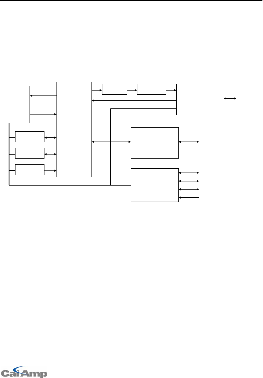
OSMAC Base User Manual
Page 39
Manu.01_0405
11 Specifications
Principles of Operation
The OSMAC Base is a multi-functional unit which can be used to communicate between the built-in
speaker/microphone, pagers, two-way radios and the telephone interface. The internal circuitry is
comprised of numerous elements as shown on the block diagram below. These include radio
transceiver, telephone interface, microprocessor, front panel I/O, DTMF encoder/decoder, CTCSS
encoder/decoder, speech synthesizer (DAC), microphone amplifier, speaker amplifier, analog filters,
limiting amplifier and analog switch matrix. The microprocessor controls all circuitry as needed for the
desired communication function. The encoders generate needed audio signals and the decoders
detect incoming control signals on the received audio. Analog switches route the analog signals within
the unit.
OSMAC Base Block Diagram
Encoder/Terminal general
Paging Format.................................................POCSAG ( tone, numeric, and alpha at 512, 1200 or
2400bps)
TWO-TONE and GROUP-TONE optional
Squelch formats ..............................................CTCSS or carrier squelch
Serial port protocols ........................................TAP, COMP2, COMP1
Pager database maximum size........................1000 individual pagers
Maximum page length.....................................250 characters
Maximum pre-programmed alarm message.....40 characters
Maximum number of pager groups ..................16
Maximum number of pagers per group ............75
LCD display size .............................................20 characters X 2 lines
Speaker audio.................................................1 watt maximum at <5% THD
Power supply ..................................................External 12.0V&5.0VDC, 2A, DIN connector.
Weight ............................................................3.5lbs.
Temperature range..........................................-10-+40C
Processor........................................................80386EX
Non-volatile flash memory size........................2M bytes
External keyboard interface.............................Standard PS/2
Telephone interface.........................................RJ-11 female, DTMF signaling
Speake
Mic
Control
Antenn
Analog
Switch
Matrix
Radio
Transceiver
Front
Panel
Filter
Limiter
Telephone
Interface
Phone
DTMF
CTCSS
DAC
Microprocesso
r
RS232 Port 1
RS232 Port 2
Keyboard
Alarm

OSMAC Base User Manual
Page 40
Manu.01_0405
DTMF signaling timing.....................................> 40 mS (telco receive mode)
> 100 mS (radio receive mode)
100 mS (telco transmit mode)
Alarm/data inputs ............................................8
RF Section
Frequencies ....................................................VHF and UHF band models available
RX channel spacing ........................................12.5kHz (narrowband) or 25kHz (wideband) models
available
TX power output..............................................Between 1 and 5 watts, depending on model
Selectable via internal jumper for some models
Factory programmed for others
RF Modulation.................................................Frequency Modulation
RF Data Rate………………………..……………9600bps Maximum, 12.5 KHz channel

OSMAC Base User Manual
Page 41
Manu.01_0405
12 Alignment
12.1 Adjustments
The following table lists the internal adjustments.
Reference
Designator Function
Rear Panel Squelch/carrier detect threshold
level.
Rear Panel LCD Contrast.
R20 Receive audio level.
R16 RX audio bias.
R32 CTCSS encode level.
R34 Paging data level.
R41 Voice limiter.
R60 Microphone gain.
R52 Telco audio to transmitter level.
R69 Telco line driver level.
12.2 Alignment Procedure
12.2.1 General Setup
1. Apply DC power to the unit. Connect the service monitor to the ANT port.
2. Download the Flash code to the unit if it is not already programmed. Hold down the "-" key while
powering up the unit to enter Flash code programming mode. See the section on "Firmware
Updating" for additional information.
3. Adjust the LCD contrast control on the rear panel of the unit.
12.2.2 Radio Interface
This procedure assumes a properly tuned transceiver is installed in the unit. You will need a DC
power source, service monitor, oscilloscope, and DVM. Full System Deviation =5.0 kHz for wide-band
versions, and FSD=2.5 kHz for narrow-band versions. Depending upon the type bandwidth of the
transceiver used, you will have to make slightly different adjustments.
1. Program the unit’s transmit and receive frequencies. Disable sub-audible signaling.
2. Set the TX bandwidth to “wide band” or "narrow band" depending on the bandwidth of the
transceiver unit installed.
3. Generate an RF carrier on the receive frequency, 1 kHz tone, 60% FSD = 3 kHz (wideband units) /
1.5 kHz. (narrowband units), RF level 10 uV.
4. Adjust R16 for a 1.5 V p-p (530 mV RMS) signal on TP8.
5. Adjust the RF generator to .35 uV. Adjust the squelch (located on the rear panel) so that the
carrier detect LED is on, and so that it goes off when the RF level is below .25 uV.

OSMAC Base User Manual
Page 42
Manu.01_0405
12.2.3 Telco Interface - Receive Mode
1. Generate an RF carrier on the receive frequency, 1 kHz tone, 60% FSD = 3 kHz / 1.5 kHz. RF
level 10 uV.
2. Connect the TELCO line to the RX audio by holding the 1 button down on power up to bring-up the
test mode, then enter the password and press 6 F1 and F2.
3. Adjust R69 (telco line level) for a level of –13 dBm on the line.
4. Disable the RX audio by pressing F2 twice more. Generate a DTMF tone from the by pressing 3
and then F4.
5. Verify that the line level is between -15 and -12 dBm. Then press the DOWN arrow to turn off the
DTMF.
12.2.4 Telco Interface - Transmit Mode
1. Set the service monitor to measure the transmitter's FM deviation.
2. Generate a 2500 Hz tone onto the TELCO line from an external test instrument with a power level
of > 5 dBm into 600 ohms.
3. Connect the TELCO to the transmitter by pressing F1, then press F2 twice to key the transmitter.
4. Adjust R52 clockwise for maximum gain, then adjust R41 (limiter) for 4.5 kHz / 2.25 kHz deviation.
5. Adjust the TELCO signal to a power level of -15 dBm.
6. Adjust R52 so that the deviation is at half scale (2.25 kHz / 1.125 kHz).
12.2.5 Paging Modulation
1. Turn the unit off.
2. Generate a 1200 baud paging test signal by holding the 1 button down upon power up, then
entering the password and pressing 6 1 2. Specify an ON time of 30000 mS and an OFF time of
0mS.
3. Adjust R34 for 5 kHz / 2.5 kHz (0 to peak) deviation.
4. Turn off the power to the unit.
12.2.6 Voice Modulation & CTCSS
1. Turn the unit back on.
2. Key the transmitter using the F3 key. Adjust R160 so the carrier is on frequency.
3. Adjust R60 (mic gain) for 3 kHz / 1.5 kHz deviation when speaking into the mic with a normal voice
level from a distance of about 1 foot away.
4. Enable a 100 Hz CTCSS encoder on the transmit frequency.
5. Key the transmitter with the F3 key. Adjust R32 for 500 Hz / 250 Hz deviation of the CTCSS tone.
6. Measure the transmitter's power level to verify that it is set to the desired level with the internal
jumpers.

OSMAC Base User Manual
Page 43
Manu.01_0405
13 Appendix A – Frequency Coordinators
The following is a list of frequency coordination agencies. Contact the agency that coordinates
frequency assignments for the industry your business is in.
13.1 For frequencies designated with an "IW" in Section 90.35 of the
Commission's rules:
UTC, The Telecommunications Association
Attn: Frequency Coordination Department
1140 Connecticut Avenue, NW, Suite 1140
Washington, DC 20036
Phone: (202) 872-0030, Fax: (202) 331-7639
13.2 For frequencies designated with an "IP" in Section 90.35 of the
Commission's rules:
Petroleum Frequency Coordinating Committee (PFCC)
c/o Industrial Telecommunications Association, Inc.
Attn: Frequency Coordination Department
1110 North Glebe Road, Suite 500
Arlington, Virginia 22201
Phone: (703) 528-5115
13.3 For frequencies designated with an "LR" in Section 90.35 of the
Commission's rules:
Association of American Railroads
Communications and Signal Division
Attn: Chris Allman
50 F Street, NW
Washington, DC 20001
Phone: (202) 639-2217
13.4 For all other frequencies, applicants may use any of the coordinators
listed above or one of the following:
American Automobile Association (AAA)
Attn: Gary M. Ruark
1000 AAA Drive, Mailspace 15
Heathrow, Florida 32746-5063
Phone: (407) 444-7786, Fax: (407) 444-7380
Personal Communications Industry Association (PCIA)
Attn: Lori Baynton, Director
Frequency Coordination Department
500 Montgomery Street, Suite 700
Alexandria, Virginia 22314-1561
Phone: 1-800-759-0300, Fax: (703) 739-0300

OSMAC Base User Manual
Page 44
Manu.01_0405
Central Station Alarm Association (CSAA)
Attn: Robert Bitton, President
P.O. Box 775
1565 Union Avenue
Union, New Jersey 07083-0775
Phone: (908) 810-8822, Fax: (908) 810-8844
Forest Industries Telecommunications (FIT)
Attn: Kenton E. Sturdevant
871 Country Club Road, Suite A
Eugene, Oregon 97401
Phone: (541) 485-8441
Manufacturers Radio Frequency Advisory Committee, Inc.(MRFAC)
Attn: Frequency Coordination Department
1041 Sterling Road, #106
Herndon, Virginia 20171
Phone: (703) 318-9206, Fax: (703) 318-9209
Alliance of Motion Picture and Television Producers
c/o Industrial Telecommunications Association, Inc.
Attn: Spectrum Management Department
1110 North Glebe Road, Suite 500
Arlington, Virginia 22201
Phone: (703) 528-5115
American Trucking Association, Inc. (ATA)
Attn: Kathy Garrett
2200 Mill Road
Alexandria, Virginia 22314
Phone: (703) 838-1731
Newspaper Association of America (NAA)
c/o Industrial Telecommunications Association, Inc.
Attn: Frequency Coordination Department
1110 North Glebe Road, Suite 500
Arlington, Virginia 22201
Phone: (703) 528-5115
Industrial Telecommunications Association, Inc.
Attn: Frequency Coordination Department
1110 North Glebe Road, Suite 500
Arlington, Virginia 22201
Phone: (703) 528-5115
International Taxicab and Livery Association (ITLA)
Attn: Cecelia M. Hayes
3849 Farragut Avenue
Kensington, Maryland 20895
Phone: (301) 946-5702
Telephone Maintenance Frequency Advisory Committee (TELFAC)
c/o Industrial Telecommunications Association, Inc.
Attn: Frequency Coordination Department
1110 North Glebe Road, Suite 500
Arlington, Virginia 22201
Phone: (703) 528-5115

OSMAC Base User Manual
Page 45
Manu.01_0405
14 Appendix B – Regulatory Compliance Information Statements
14.1 Federal Communications Commission Part 68 Statements:
This equipment complies with Part 68 of the FCC rules. Located on the equipment is a label that
contains, among other information, the FCC registration number and ringer equivalence number
(REN.) If requested, this information must be provided to the telephone company.
The REN is used to determine the quantity of devices which may be connected to the telephone line.
Excessive REN’s on the telephone line may result in the devices not ringing in response to an
incoming call. In most, but not all areas, the sum of the REN’s should not exceed five (5.0). To be
certain of the number of devices that may be connected to the line, as determined by the total REN’s
contact the telephone company to determine the maximum REN for the calling area.
This equipment cannot be used on the telephone company-provided coin service. Connection to Party
Line Service is subject to State Tariffs.
If this equipment causes harm to the telephone network, the telephone company will notify you in
advance that temporary discontinuance of service may be required. If advance notice isn’t practical,
the telephone company will notify the customer as soon as possible. Also, you will be advised of your
right to file a complaint with the FCC if you believe it is necessary.
The telephone company may make changes in its facilities, equipment, operations, or procedures that
could affect the operation of the equipment. If this happens, the telephone company will provide
advance notice in order for you to make the necessary modifications in order to maintain uninterrupted
service.
If trouble is experienced with this equipment, please contact: CalAmp Corp.
Corporate Headquarters
Products Division:
1401 N. Rice Avenue
Oxnard, CA 93030
Phone: (805) 987-9000
Fax: (805) 987-8359
If the trouble is causing harm to the telephone network, the telephone company may request you to
remove the equipment from the network until the problem is resolved.
This equipment uses the following USOC jacks: RJ11C
It is recommended that the customer install an AC surge arrester in the AC outlet to which this device
is connected. This is to avoid damaging the equipment caused by local lightening strikes and other
electrical surges.
14.2 Industry Canada CS-03 Statements:
1. NOTICE: The Industry Canada label identifies certified equipment. This certification means that
the equipment meets certain telecommunications network protective, operational and safety
requirements as prescribed in the appropriate Terminal Equipment Technical Requirements
documents(s). The Department does not guarantee the equipment will operate to the user's
satisfaction.
Before installing this equipment, users should ensure that it is permissible to be connected to the
facilities of the local telecommunications company. The equipment must also be installed using an
acceptable method of connection. The customer should be aware that compliance with the above
conditions may not prevent degradation of service in some situations.
Repairs to certified equipment should be coordinated by a representative designated by the
supplier. Any repairs or alterations made by the user to this equipment, or equipment

OSMAC Base User Manual
Page 46
Manu.01_0405
malfunctions, may give the telecommunications company cause to request the user to disconnect
the equipment.
Users should ensure for their own protection that the electrical ground connections of the power
utility, telephone lines and internal metallic water pipe system, if present, are connected together.
This precaution may be particularly important in rural areas.
Caution: Users should not attempt to make such connections themselves, but should contact the
appropriate electric inspection authority, or electrician, as appropriate."
2. The Ringer Equivalence Number (REN) of this device is 0.6
NOTICE: The Ringer Equivalence Number (REN) assigned to each terminal device provides an
indication of the maximum number of terminals allowed to be connected to a telephone interface.
The termination on an interface may consist of any combination of devices subject only to the
requirement that the sum of the Ringer Equivalence Numbers of all the devices does not exceed
5.”
3. The standard connecting arrangement (telephone jack type) for this equipment is CA11A.

OSMAC Base User Manual
Page 47
Manu.01_0405
15 Appendix C – “Voice Prompt” Technical Details
VoicepromptfilesarelinkedwiththeOSMAC Base object code as the final part of the build process.
Voice prompts of any language or any speaker's voice may easily be incorporated.
Voice prompt files must be recorded in the following formats:
1. File Format:. wav
2. Encoding Format: PCM
3. Bits Per Sample: 8
4. Mode: Mono
5. Amplitude: Amplitude should be adjusted so voice peaks are about 75% full scale
6. Equalization: Recommend bandpass audio filtering from 300 Hz to 4 KHz prior to
recording
The following voice file names are used, with the given function and sample rates:
callend.wav Call ended 22 KHz
callext.wav Call extended 22 KHz
dialtone.wav Dial tone 11 KHz
ent_err.wav Entry error 22 KHz
msgdeliv.wav Message delivered 22 KHz
null.wav zero length null file
pagermsg.wav Enter pager message 22 KHz
pagernum.wav Enter pager number 22 KHz
phtimeo.wav Phone timeout 22 KHz
sine300.wav 300 Hz sine wave 11 KHz
sine1k.wav 1 KHz sine wave 11 KHz
talknow.wav Prompt user to talk 22 KHz
timeout.wav Timeout error 22 KHz
The following additional files are used:
language.txt Text file containing the name of the language
2005 CalAmp Corp. All rights reserved. CalAmp is a trademark of CalAmp Corp. All data subject to change without notice.
Manu.01_0405