WAGO Kontakttechnik and KG PFC200 3G PLC Controller User Manual Manual 750 8207
WAGO Kontakttechnik GmbH & Co. KG 3G PLC Controller Manual 750 8207
UserManual.wiki
>
WAGO Kontakttechnik and KG
>
PFC200 User Manual
Users Manual
Navigation menu
Upload a User Manual
Namespaces
Wiki Guide
HTML
PDF
Info
Views
User Manual
Discussion / Help
Navigation
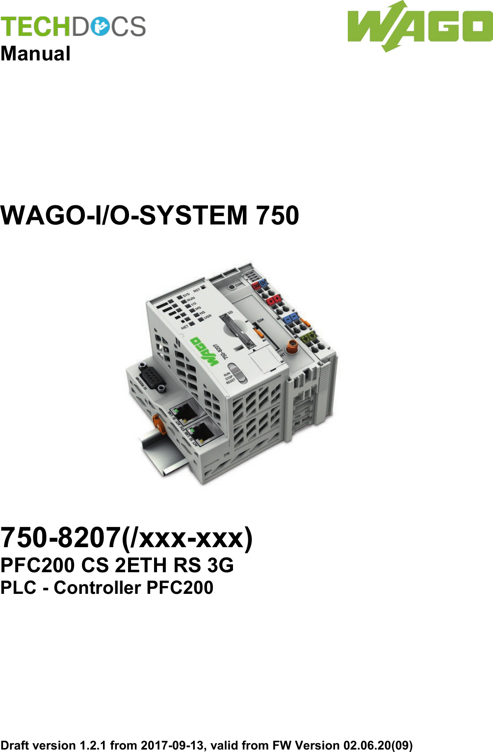
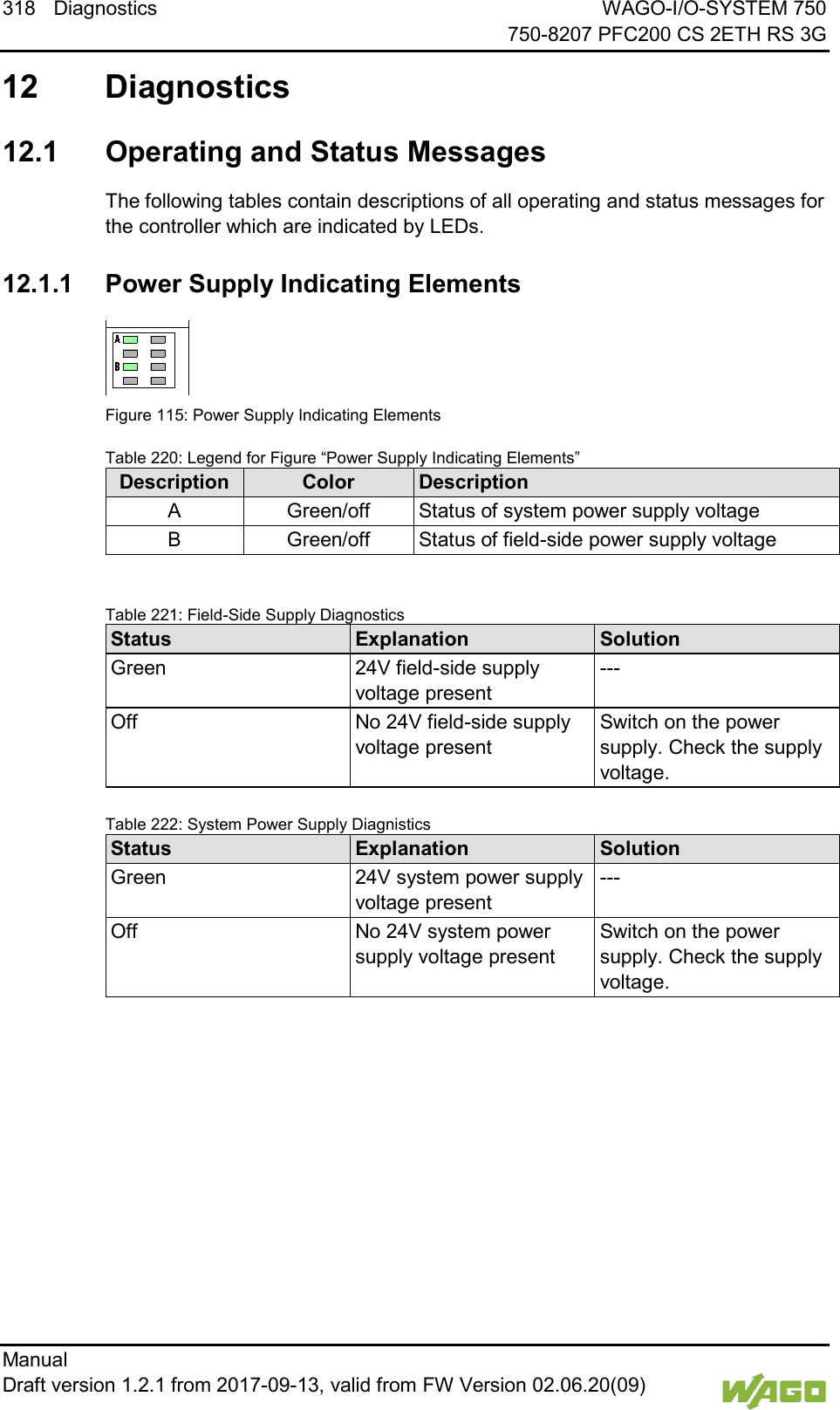
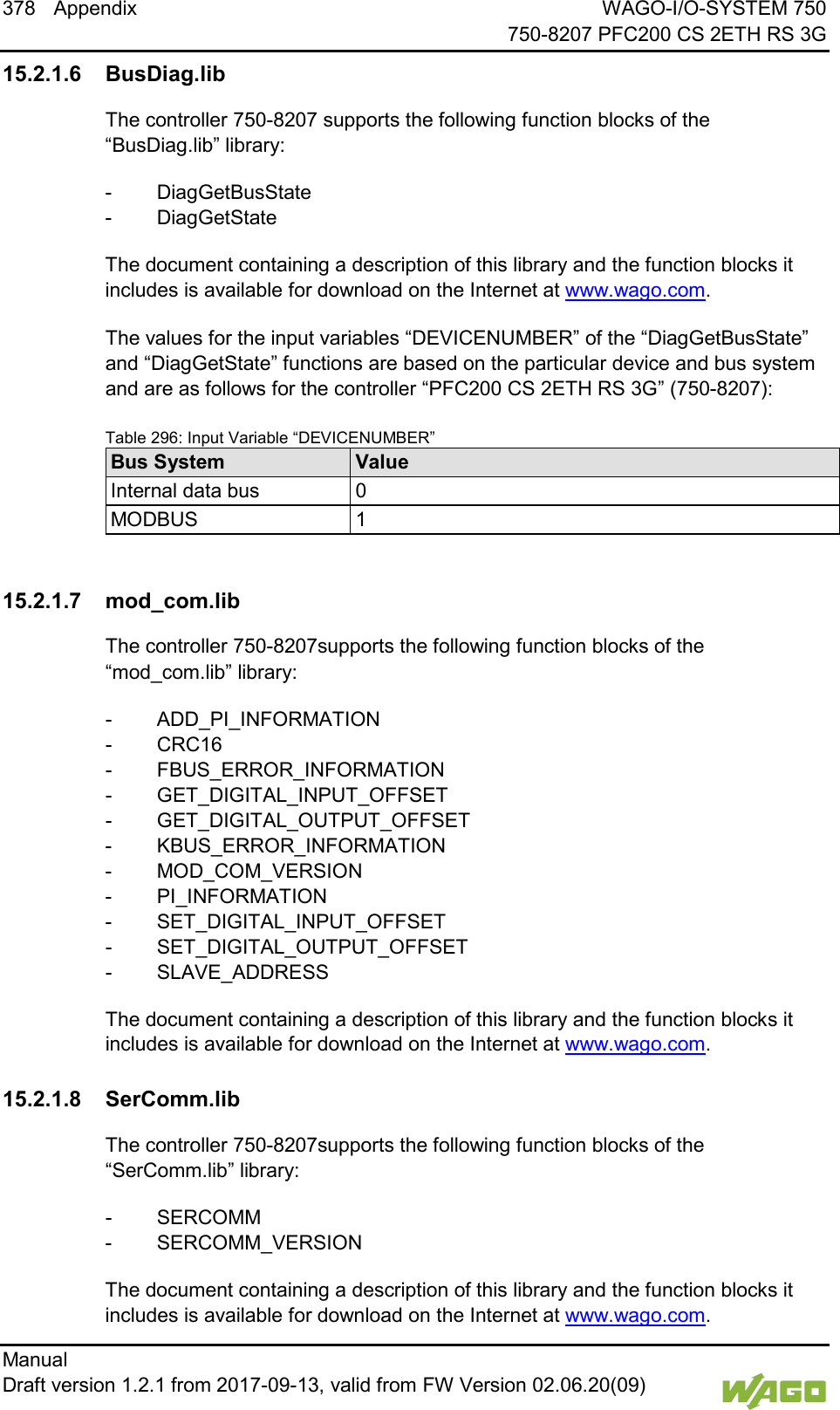
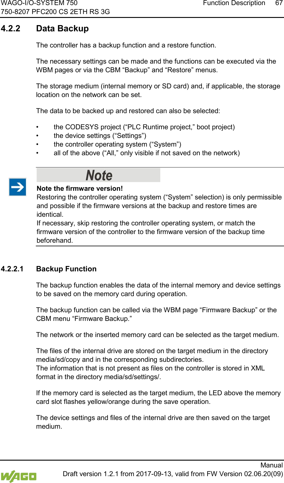
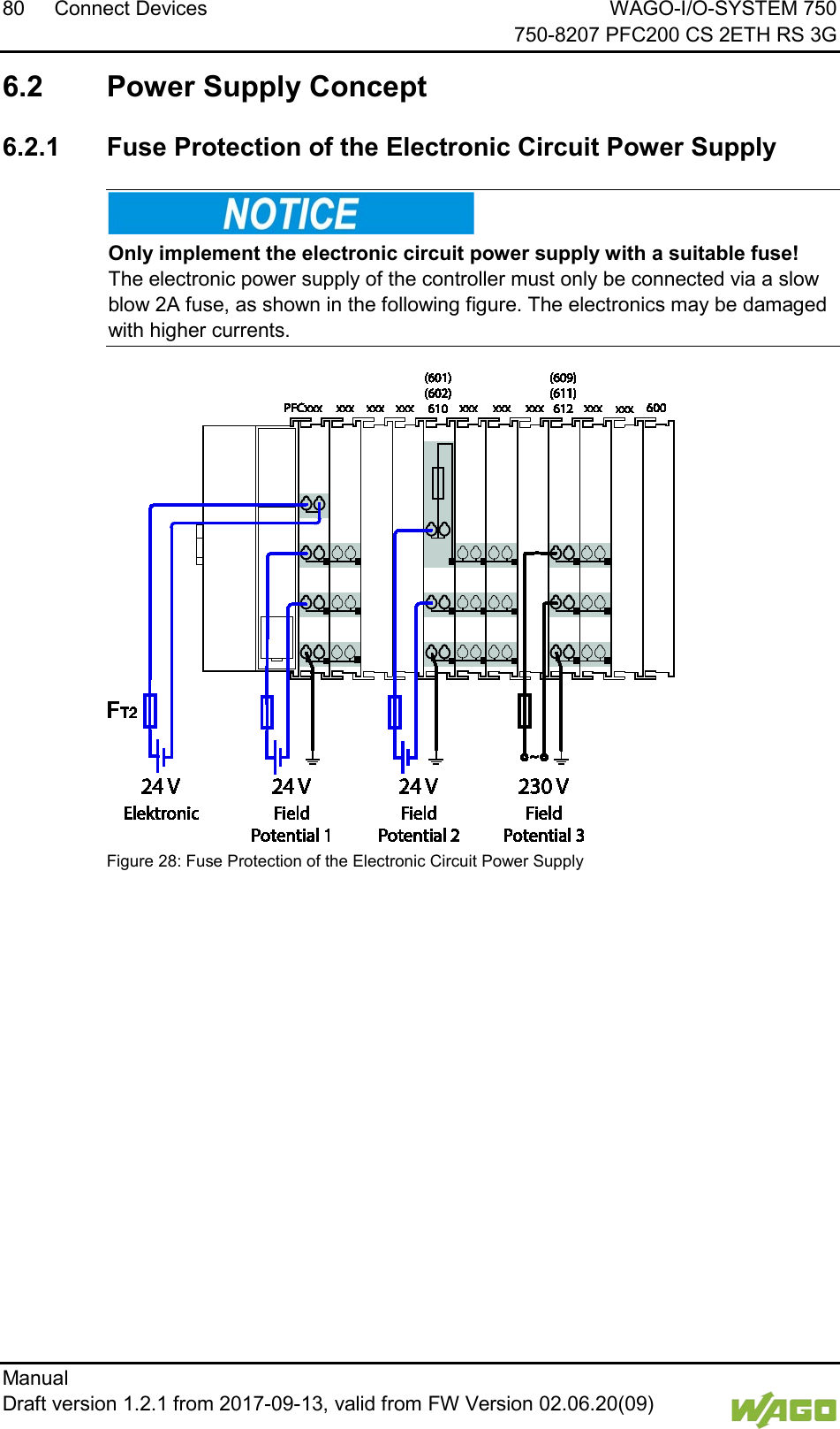
![18 Notes about this Documentation WAGO-I/O-SYSTEM 750 750-8207 PFC200 CS 2ETH RS 3G Manual Draft version 1.2.1 from 2017-09-13, valid from FW Version 02.06.20(09) 1.4 Number Notation Table 2: Number Notation Number Code Example Note Decimal 100 Normal notation Hexadecimal 0x64 C notation Binary '100' '0110.0100' In quotation marks, nibble separated with dots (.) 1.5 Font Conventions Table 3: Font Conventions Font Type Indicates italic Names of paths and data files are marked in italic-type. e.g.: C:\Program Files\WAGO Software Menu Menu items are marked in bold letters. e.g.: Save > A greater-than sign between two names means the selection of a menu item from a menu. e.g.: File > New Input Designation of input or optional fields are marked in bold letters, e.g.: Start of measurement range “Value” Input or selective values are marked in inverted commas. e.g.: Enter the value “4 mA” under Start of measurement range. [Button] Pushbuttons in dialog boxes are marked with bold letters in square brackets. e.g.: [Input] [Key] Keys are marked with bold letters in square brackets. e.g.: [F5]](https://usermanual.wiki/WAGO-Kontakttechnik-and-KG/PFC200/User-Guide-3565964-Page-18.png)
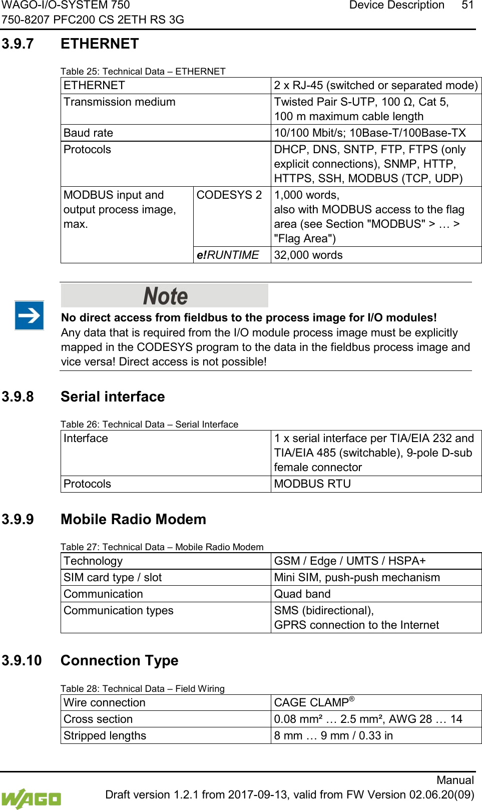
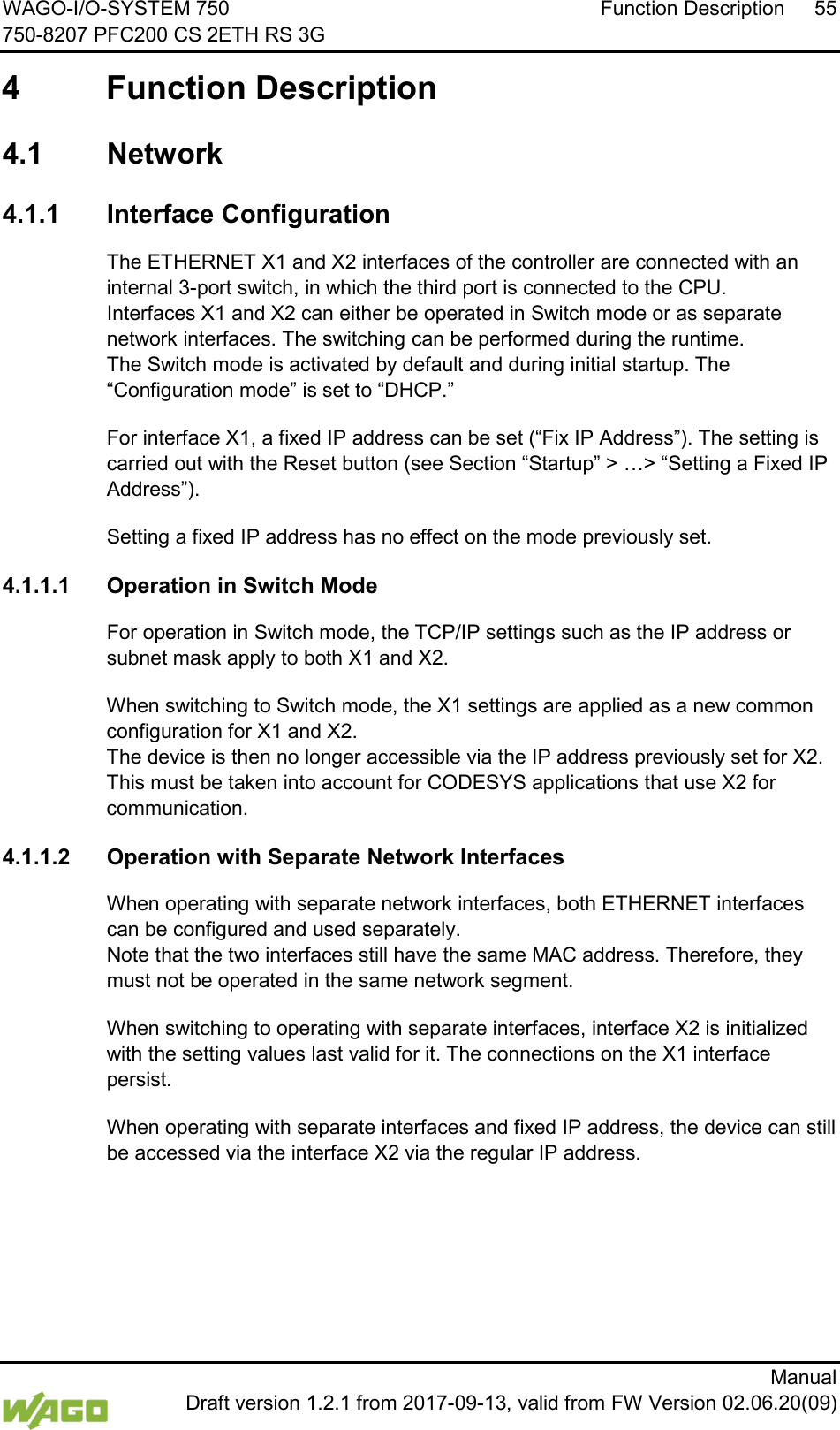
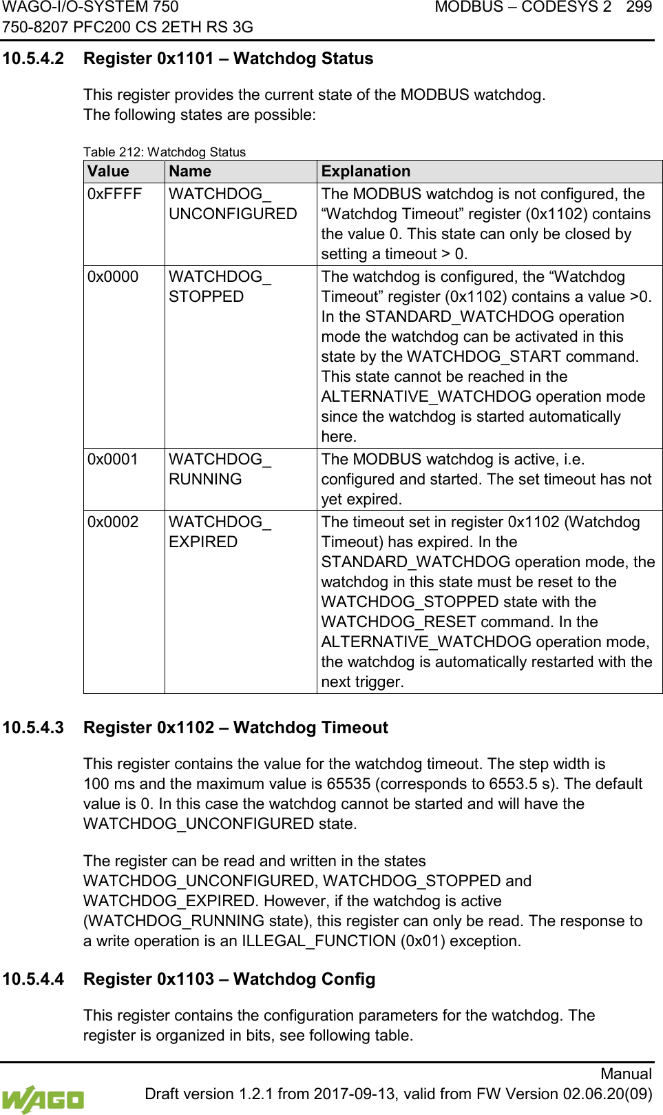
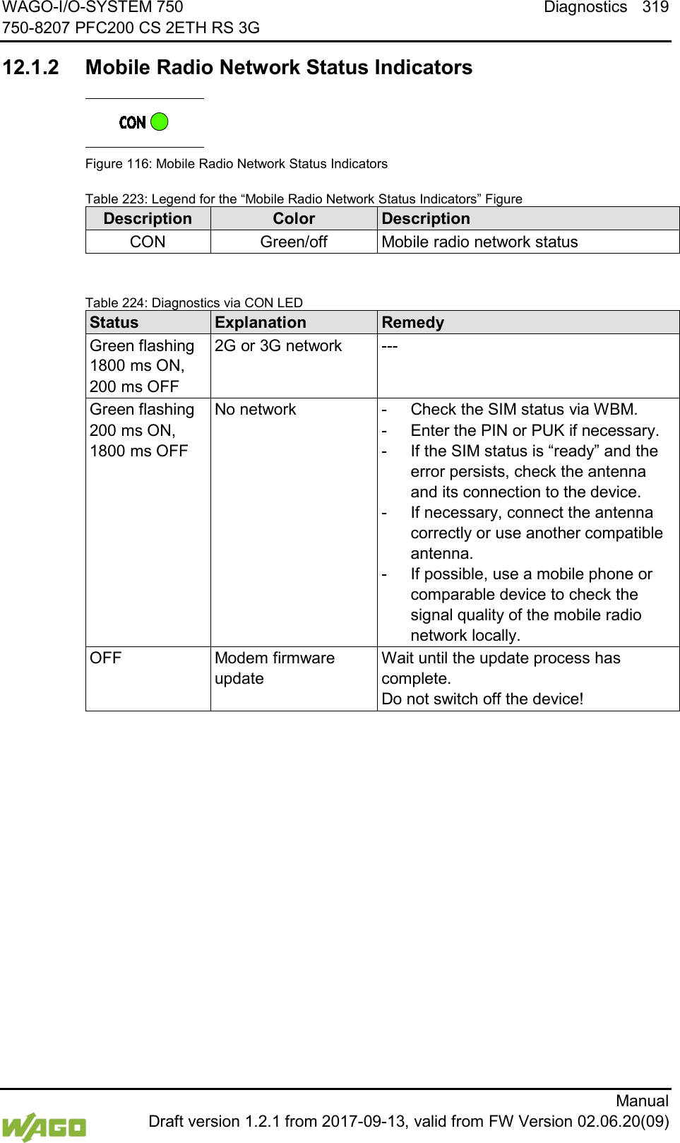
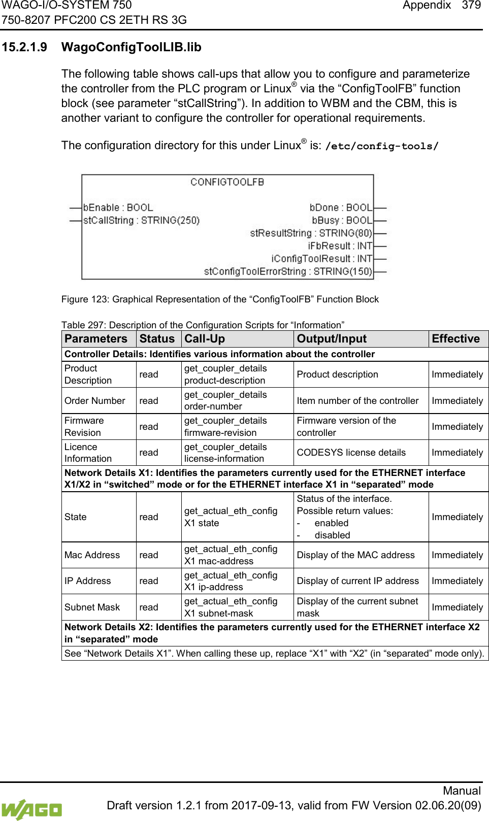
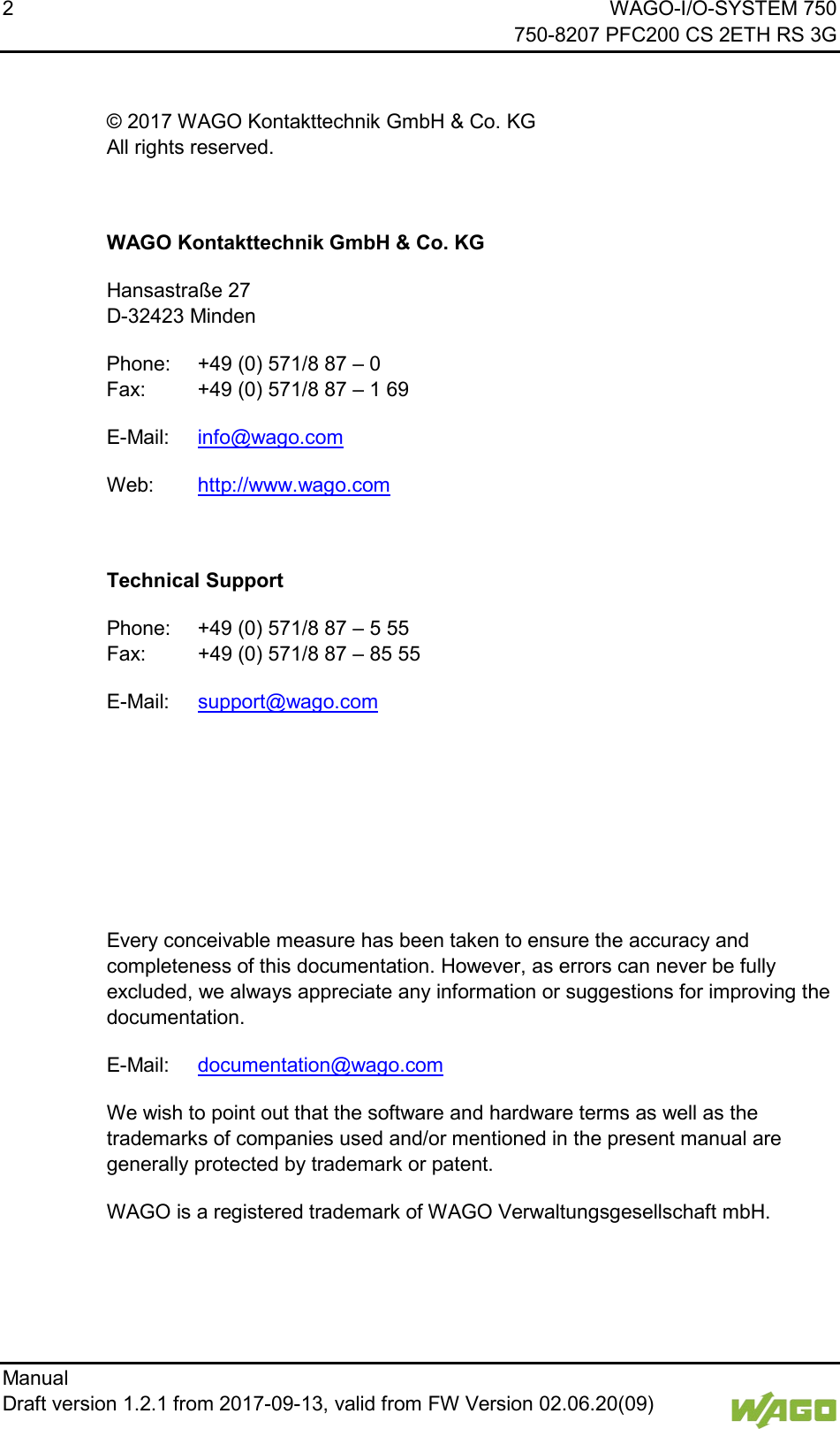
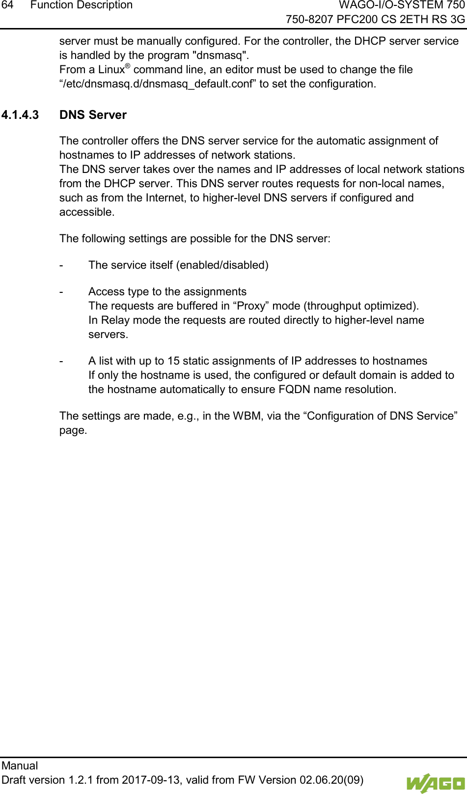
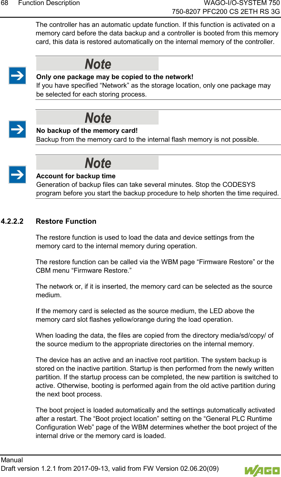
![WAGO-I/O-SYSTEM 750 Function Description 61 750-8207 PFC200 CS 2ETH RS 3G Manual Draft version 1.2.1 from 2017-09-13, valid from FW Version 02.06.20(09) There are two possibilities here: 1. Default Route If the “default” value is entered in the Destination Address field, a default route is defined. The Destination Mask field must then have the value “0.0.0.0.” 2. Route If an IP address or an address pool is entered in the Destination Address field, all data is sent to the IP address or the address pool via the entered gateway address. The gateway metric here has an important function. This determines the costs of the connection. For example, if two identical address pools are defined (192.168.1.0/24) [IP:192.168.1.1-192.168.1.254], one with a metric of 20 and the second with 192.168.1.2 and a metric of 10, the gateway with the lowest metric is used. If the address 192.168.1.2 in the above example is no longer available, e.g., due to failure, the alternative route is used automatically.](https://usermanual.wiki/WAGO-Kontakttechnik-and-KG/PFC200/User-Guide-3565964-Page-61.png)
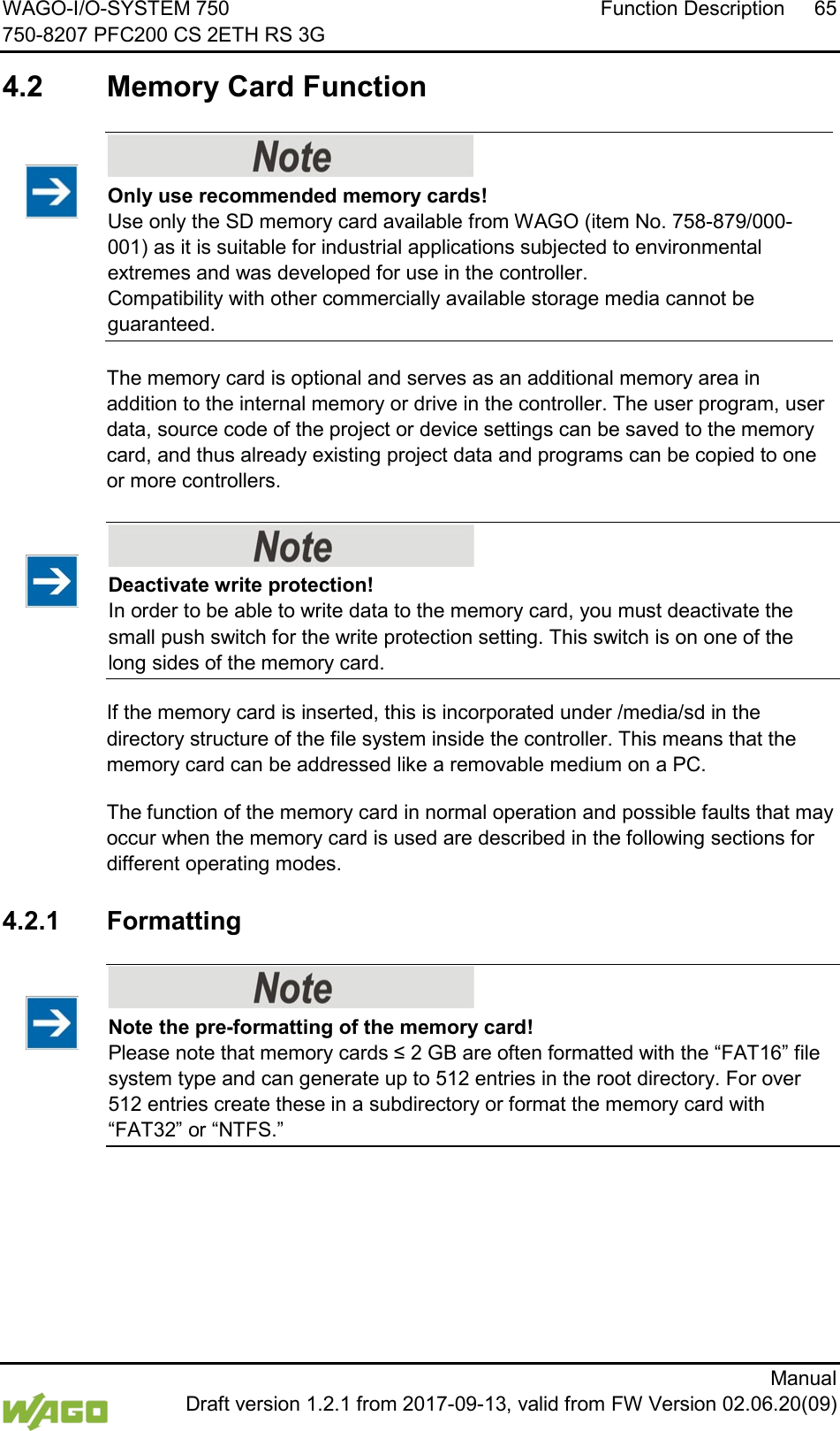
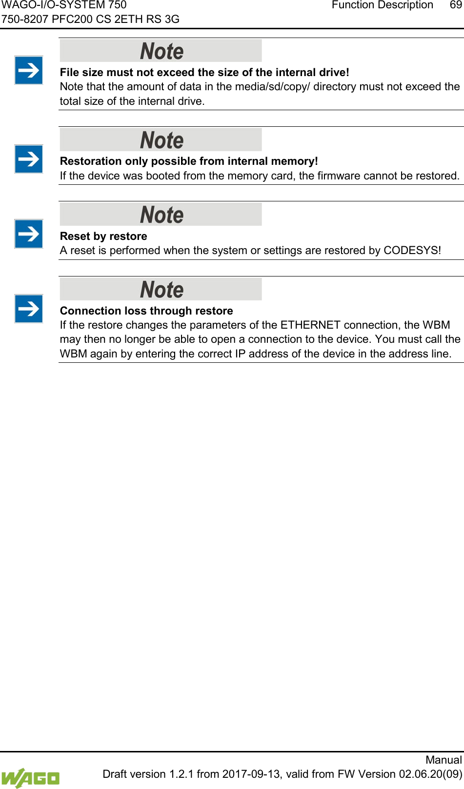
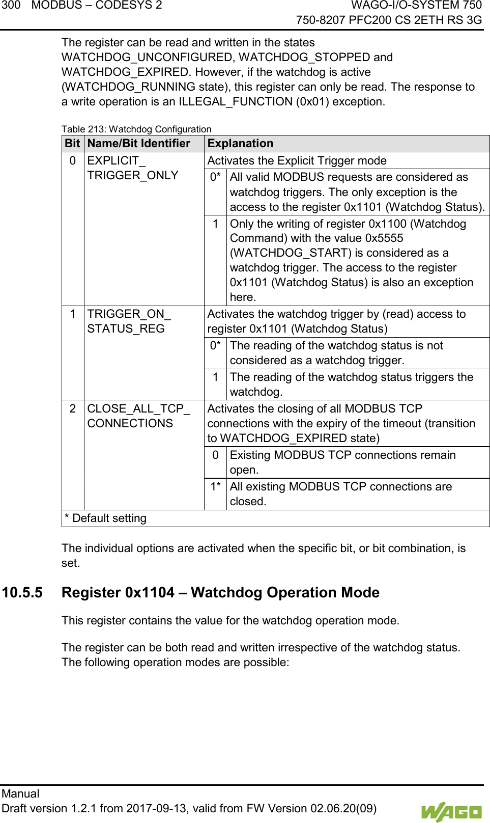
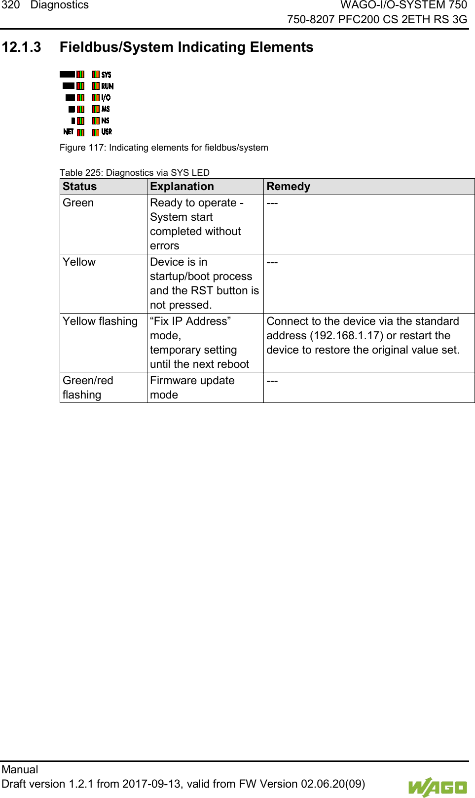
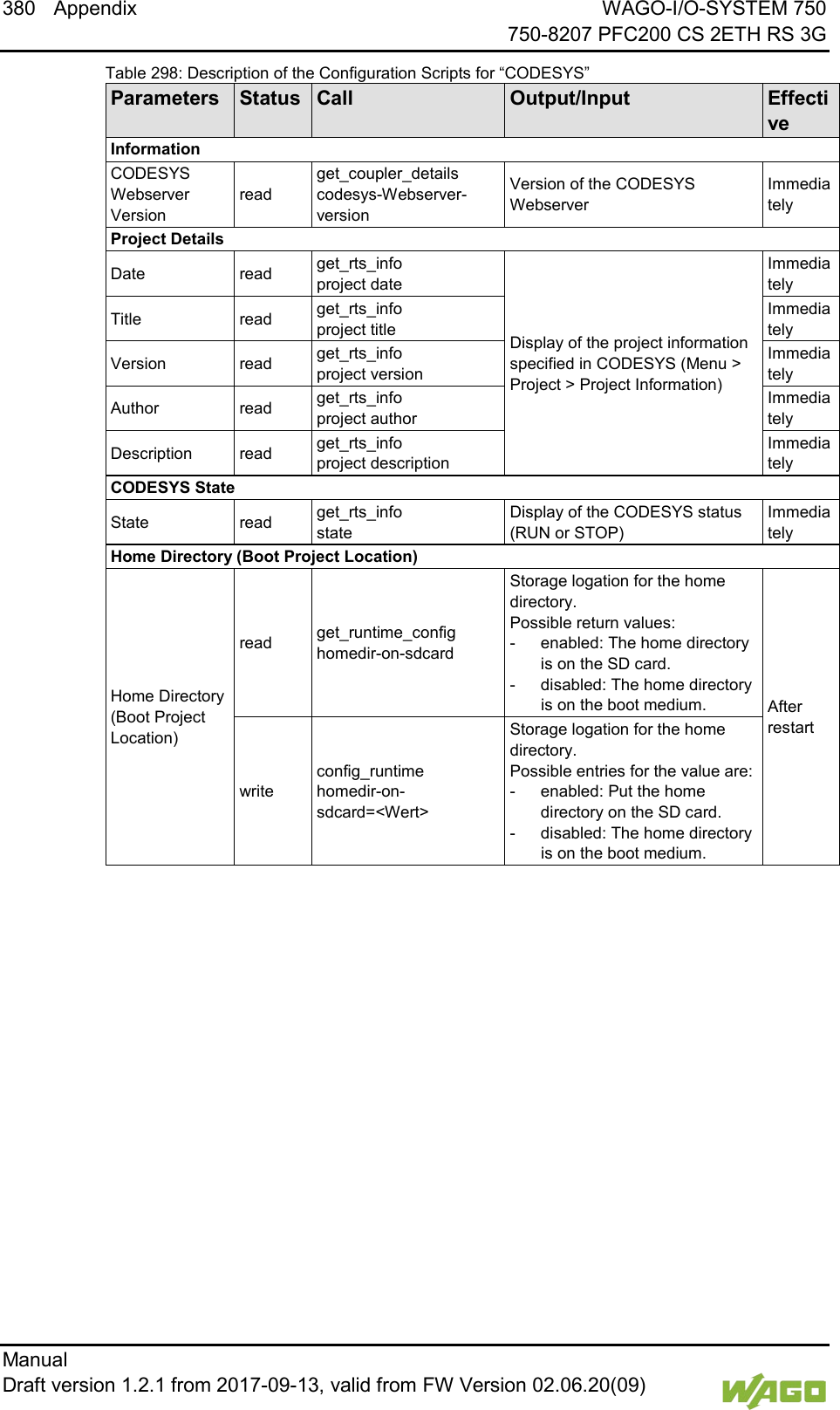
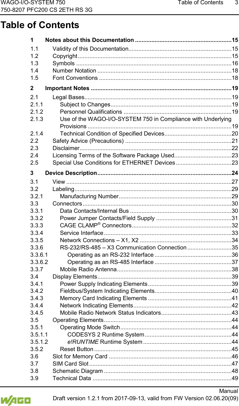
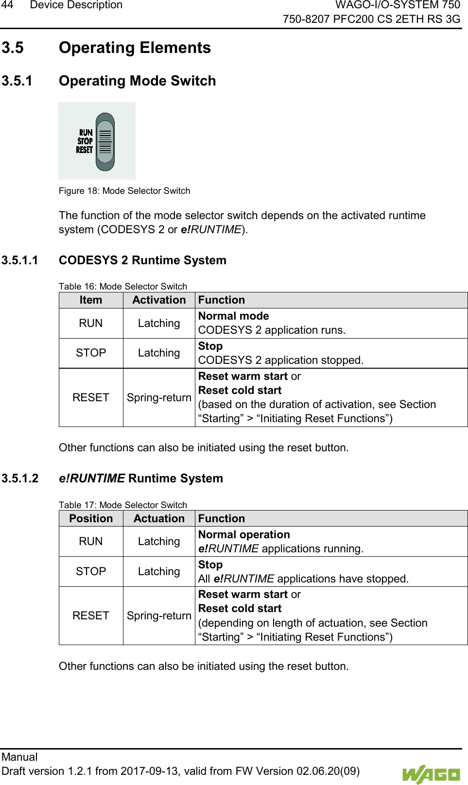
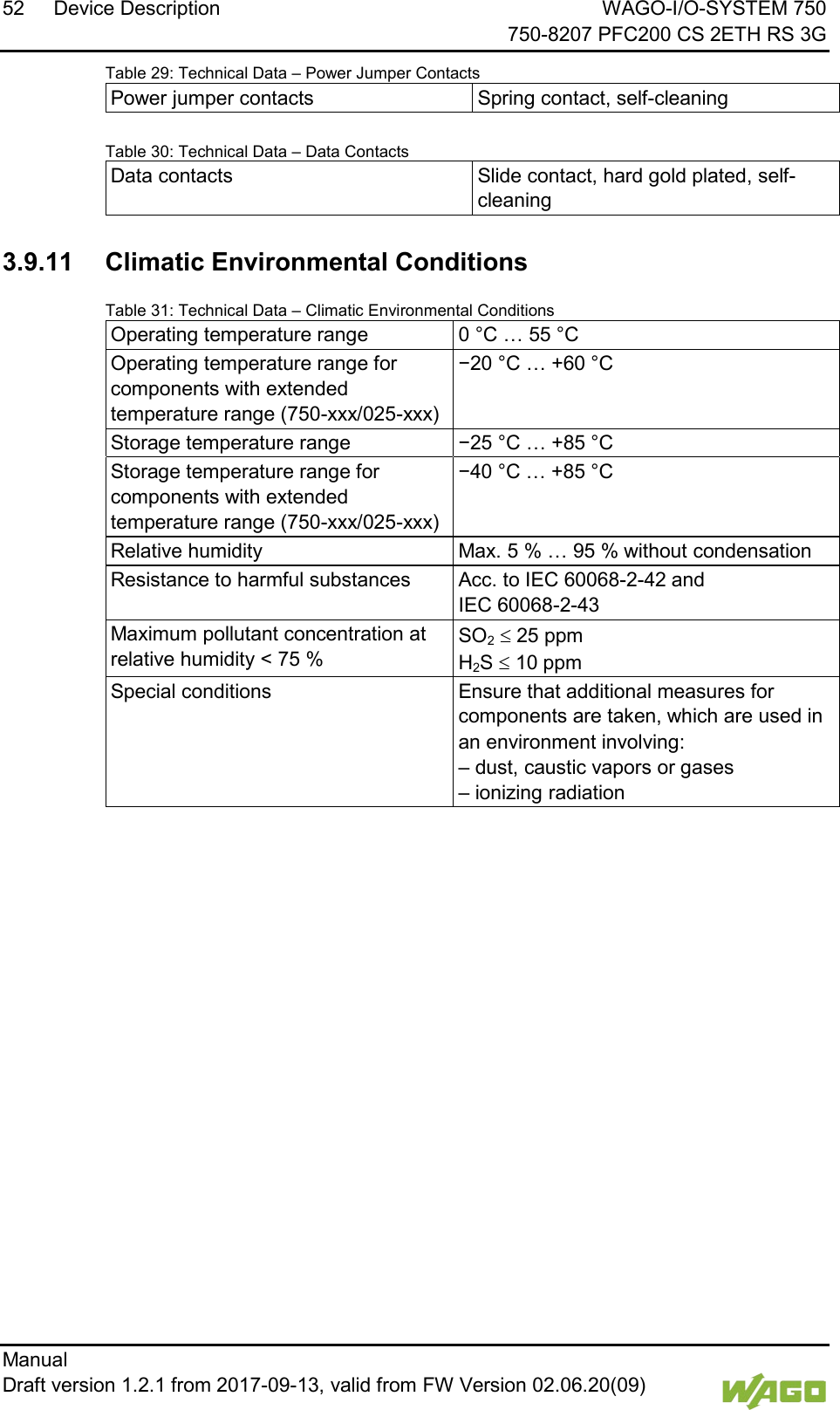
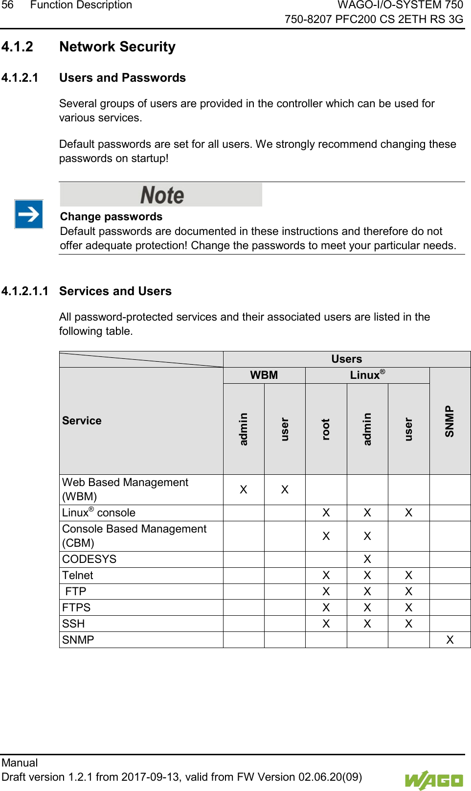
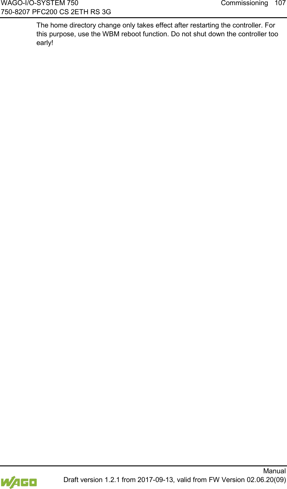
![WAGO-I/O-SYSTEM 750 Function Description 71 750-8207 PFC200 CS 2ETH RS 3G Manual Draft version 1.2.1 from 2017-09-13, valid from FW Version 02.06.20(09) 4.2.5 Setting the Home Directory for the Runtime System The home directory for the runtime system is located in the controller's internal memory by default. An existing boot project may be saved in the home directory. You can use the WBM to move the home directory for the runtime system to the memory card, e.g., to make more memory available for a large boot project or other files. Some conditions must be met before moving the directory. • A running IEC-61131 application must be stopped and the device restored to its initial state using the “Reset” function. Any boot project is deleted. • When moving the home directory to the memory card, insert a memory card formatted to support file system. Only the first partition of a memory card can be accessed at /media/sd and can be used as the home directory. Only when the two conditions are met can the “Home directory on memory card enabled” checkbox be selected from the WBM on the “PLC Runtime” page. Press the [Submit] button to apply the settings, which take effect after the next restart. No files are applied from the old to the new home directory. After moving the directory, a project must be loaded and a boot project created. It should be noted that the memory card may not be removed under any circumstances as long as the home directory is there. If an application is running, system safety can be endangered by an uncontrolled controller crash. Switching the home directory has no effect if the controller was botted from a memory card. The configuration state is saved, but only takes effect if the content of the memory card is copied to the internal memory.](https://usermanual.wiki/WAGO-Kontakttechnik-and-KG/PFC200/User-Guide-3565964-Page-71.png)
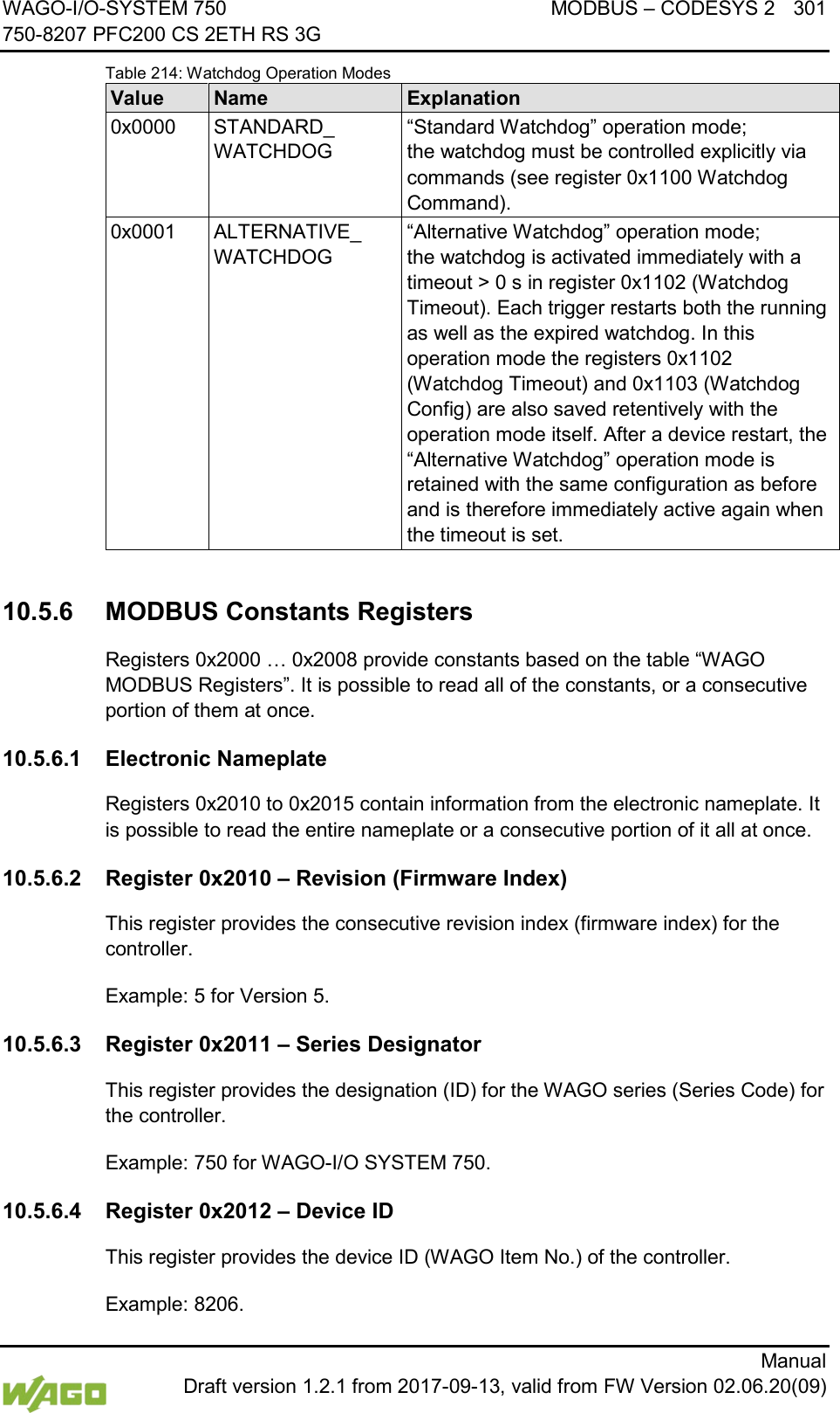
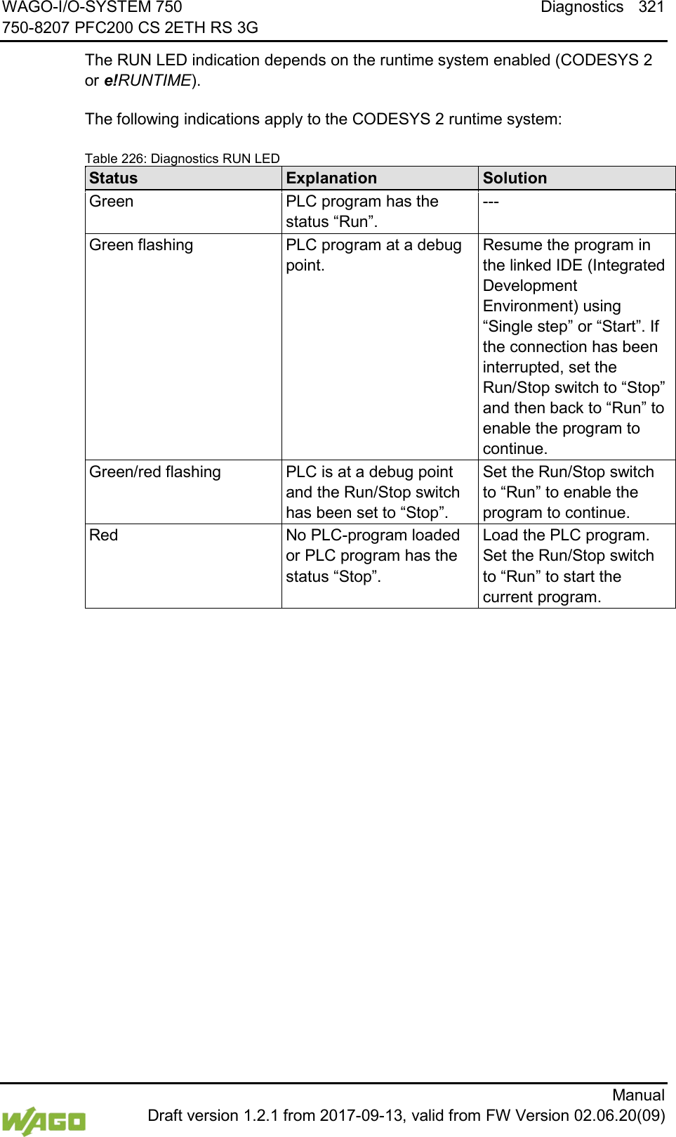
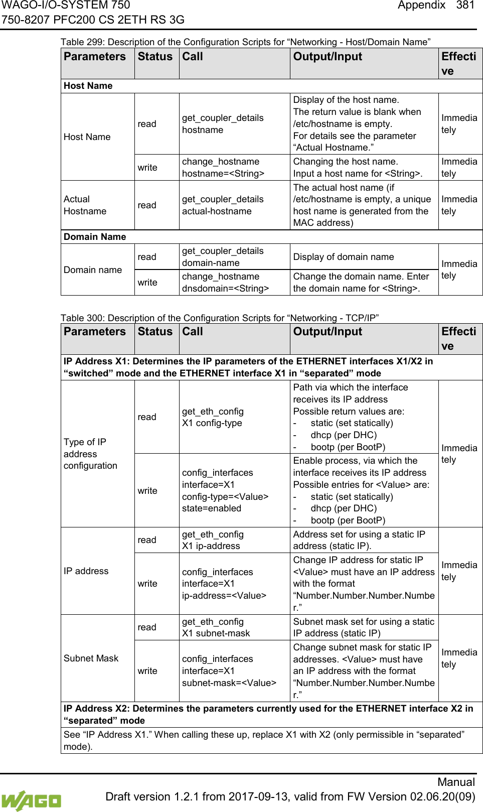
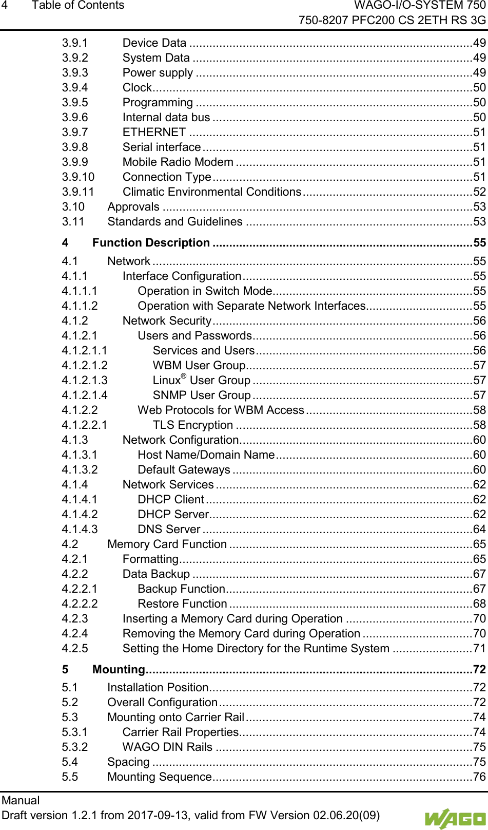
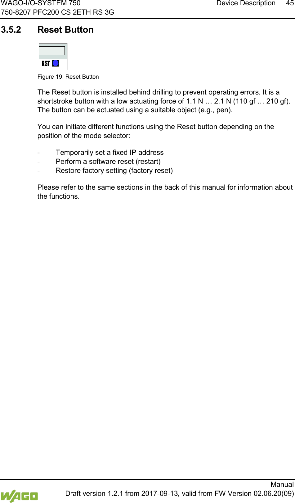
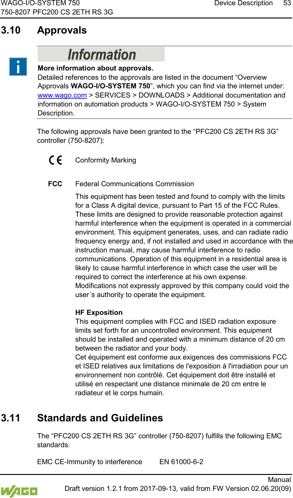
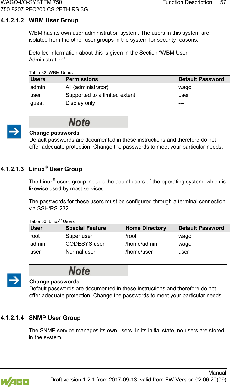
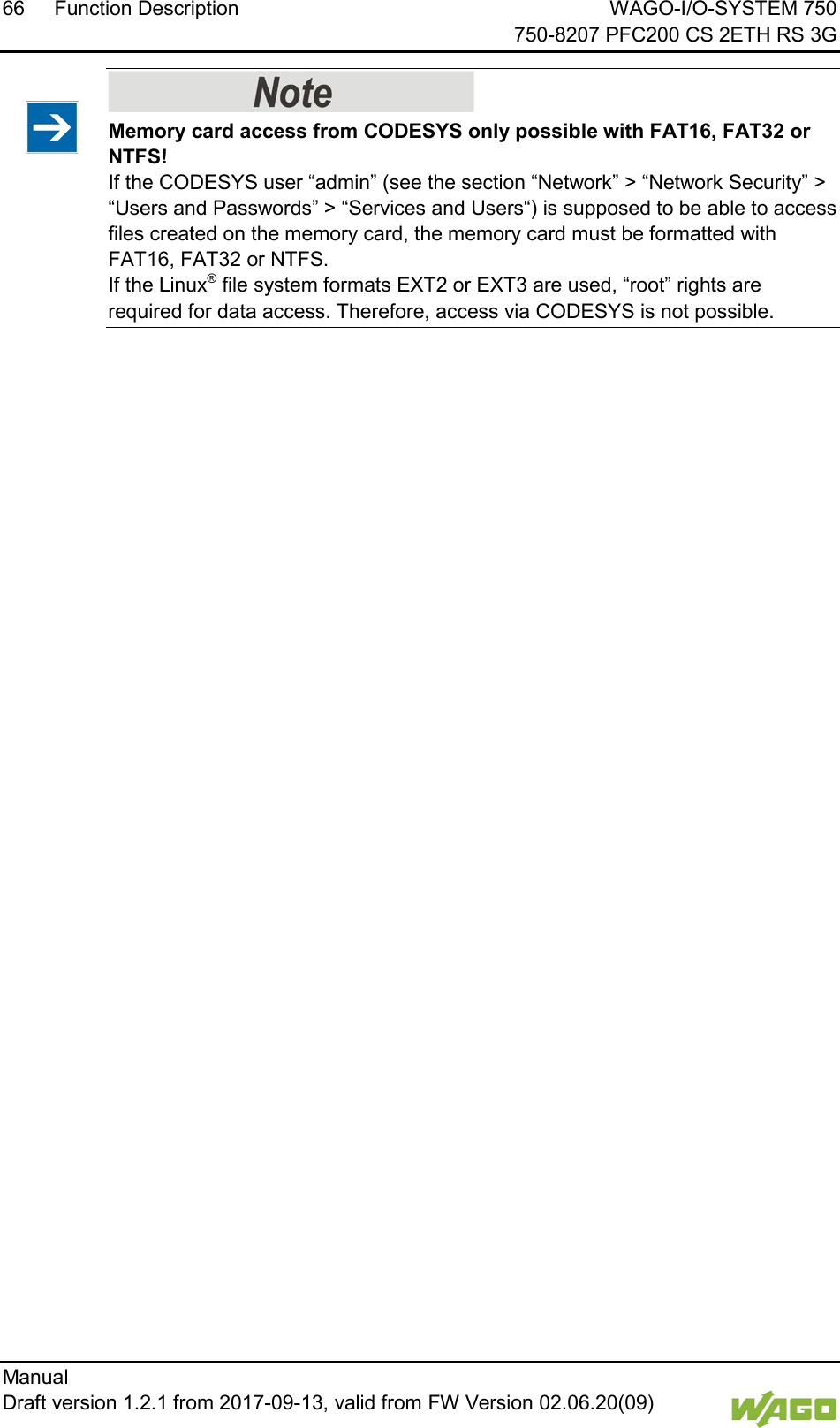
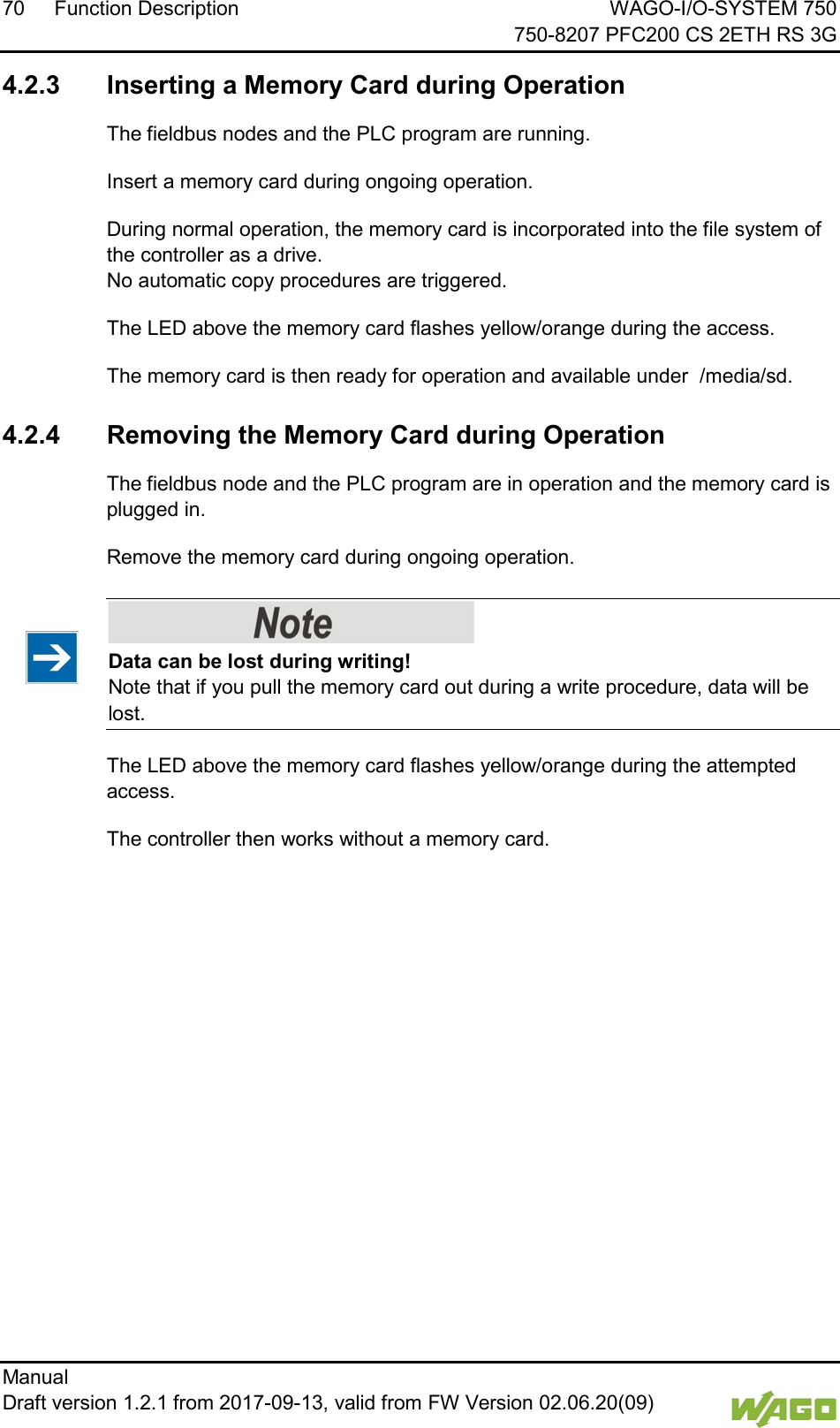
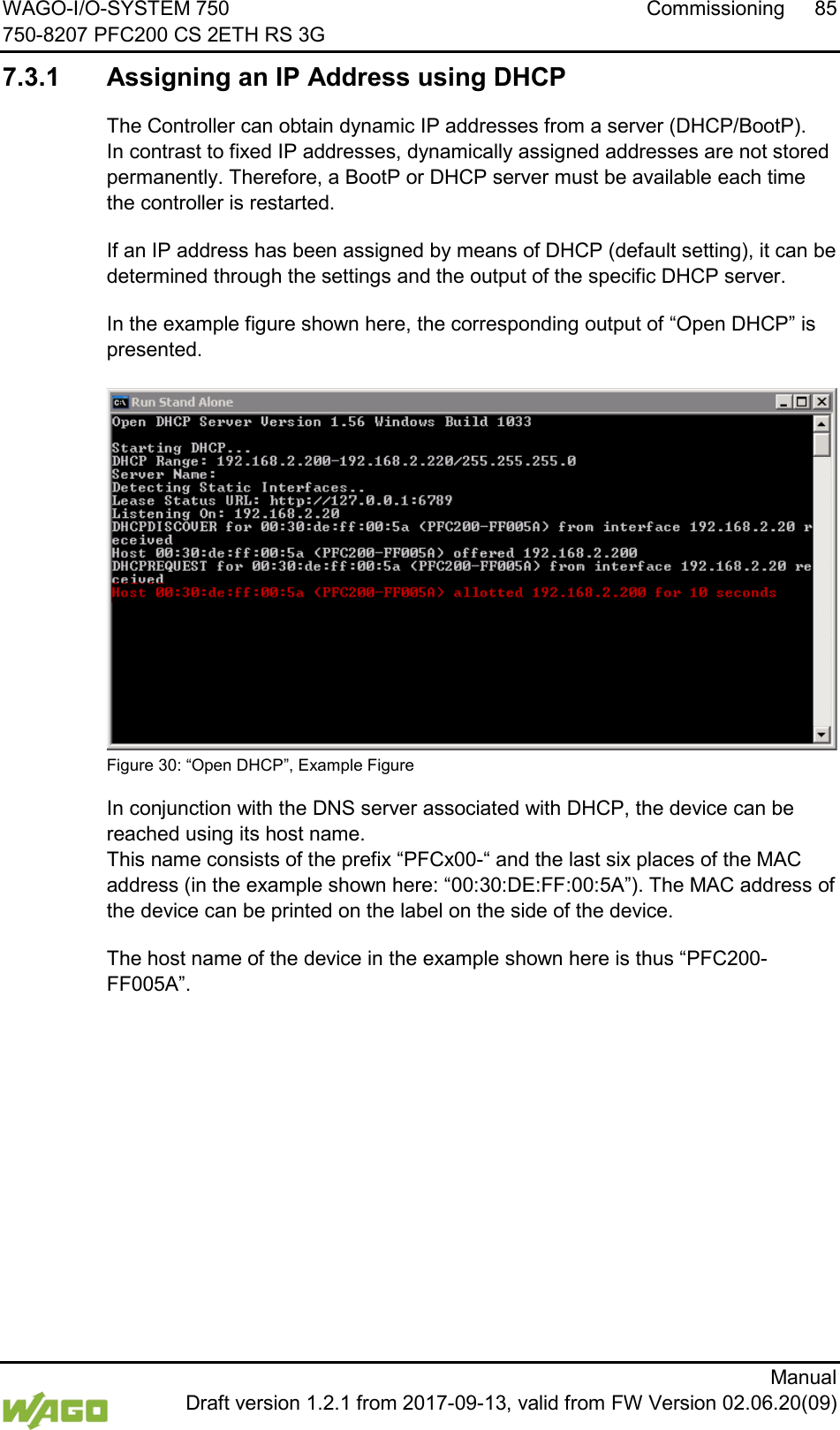
![WAGO-I/O-SYSTEM 750 Commissioning 83 750-8207 PFC200 CS 2ETH RS 3G Manual Draft version 1.2.1 from 2017-09-13, valid from FW Version 02.06.20(09) 7.2 Determining the IP Address of the Host PC To ensure that the host PC can communicate with the controller via ETHERNET, both devices must be located in the same subnet. To determine the IP address of the host PC (with the Microsoft Windows® operating system) using the MS DOS prompt, proceed as follows: 1. Open the MS DOS prompt window. To do this, enter the command “cmd” in the input field under Start > Execute… > Open: (Windows® XP) or Start > Search programs/files (Windows® 7) and then click [OK] or press [Enter]. 2. In the MS DOS prompt enter the command “ipconfig” and then press [Enter]. 3. The IP address, subnet mask and standard gateway, including the appropriate parameters, are displayed.](https://usermanual.wiki/WAGO-Kontakttechnik-and-KG/PFC200/User-Guide-3565964-Page-83.png)
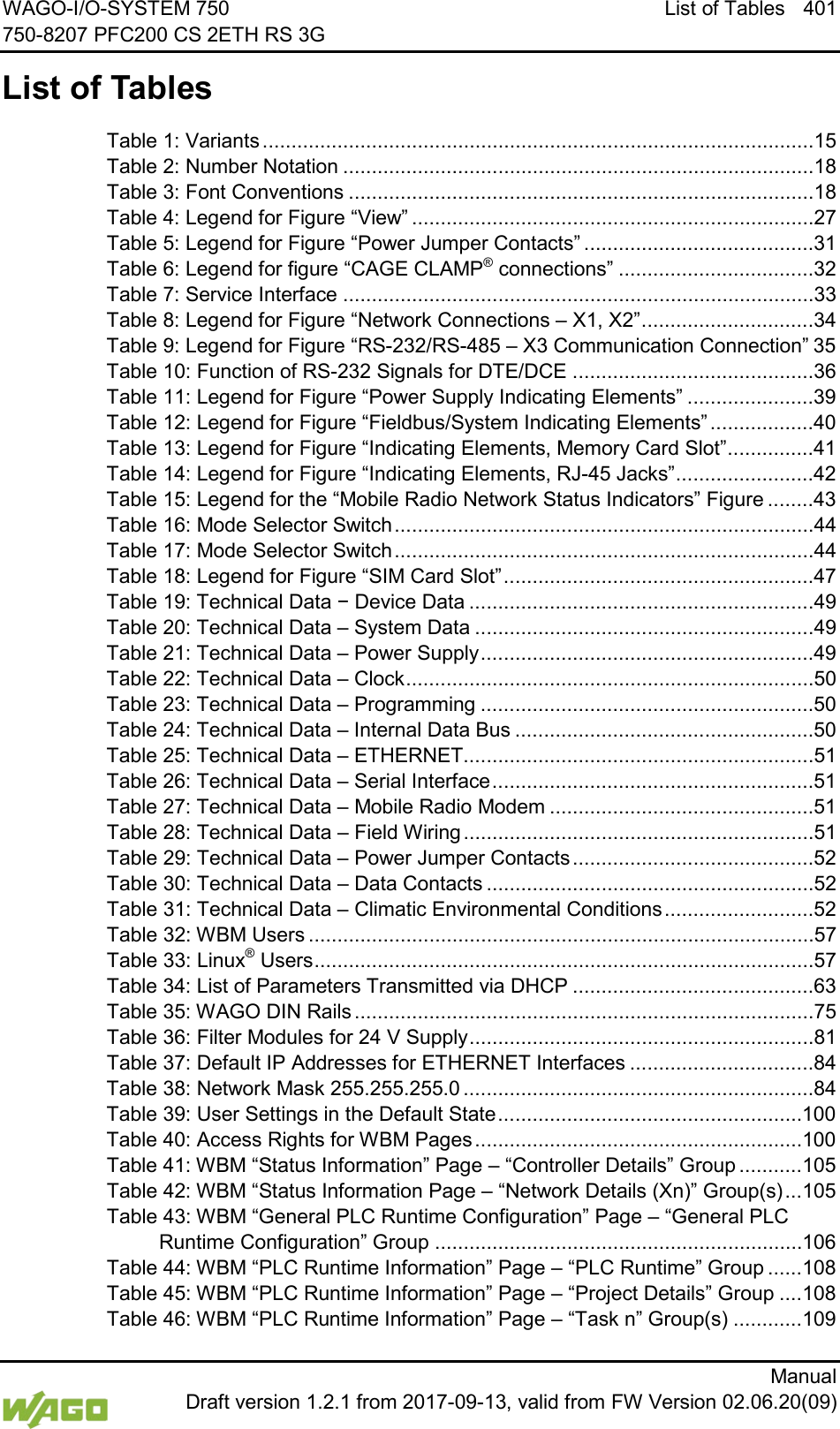
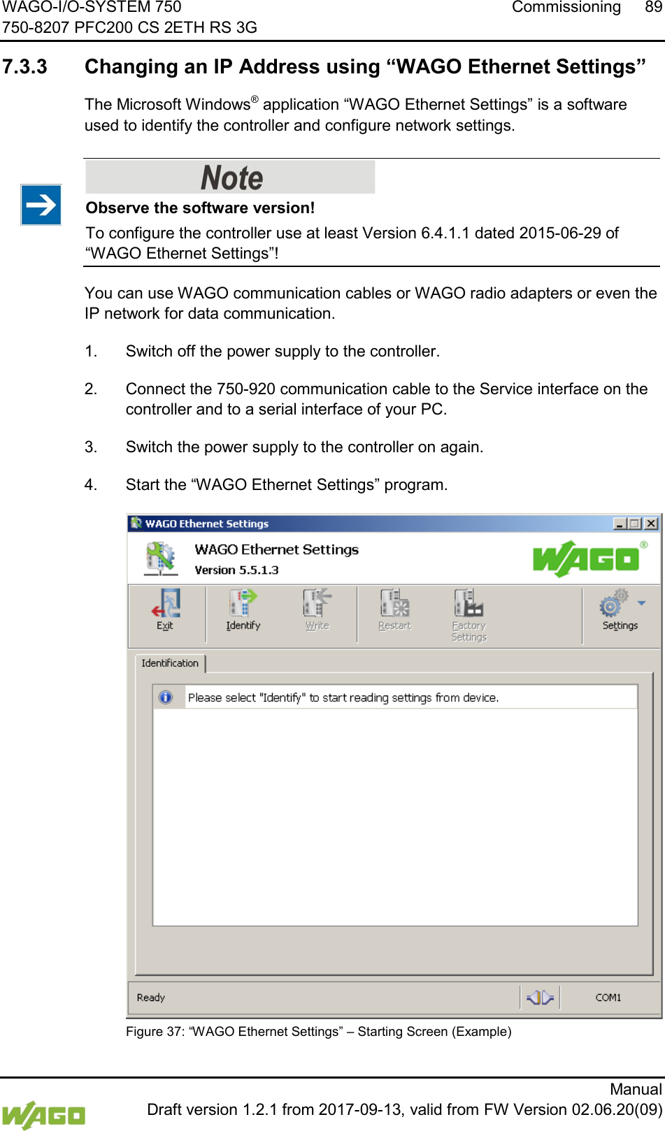
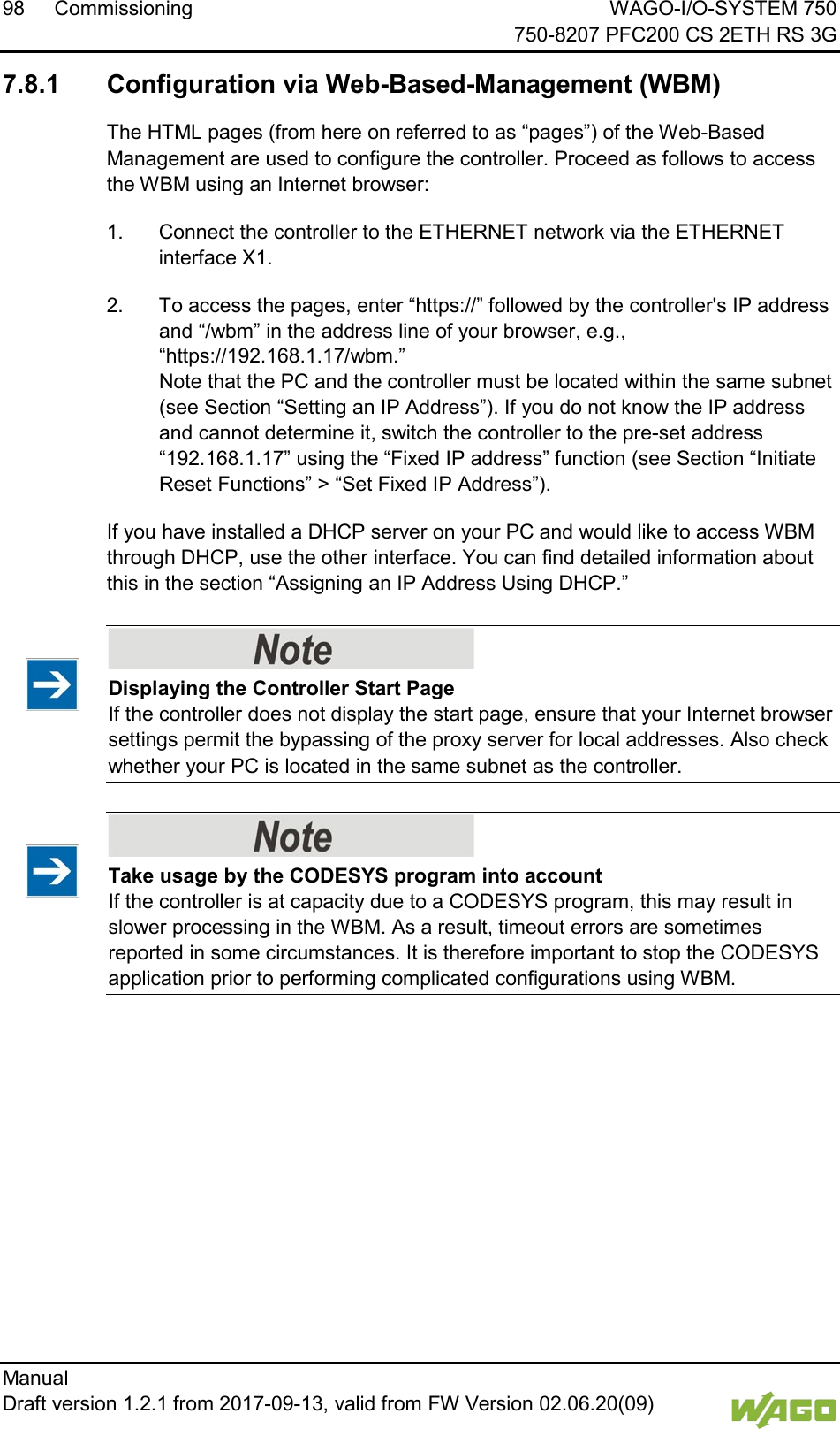
![86 Commissioning WAGO-I/O-SYSTEM 750 750-8207 PFC200 CS 2ETH RS 3G Manual Draft version 1.2.1 from 2017-09-13, valid from FW Version 02.06.20(09) 7.3.2 Changing an IP Address Using the “CBM” Configuration Tool via the Serial Interface You can also assign a new IP address to the ETHERNET interfaces X1 and X2 using the “CBM” configuration tool provided on the Linux® console. More information about “CBM” is given in the Section “Configuration.” 1. Link a PC to the X3 serial interface using a terminal program. 2. Log in to the Linux® system as a “super user.” The user name and the password are provided in the Section “Users and Passwords” > “Linux® User Group.” 3. Start the configuration tool by entering the command “cbm” on the command line and then press [Enter]. Figure 31: CBM Starting Screen](https://usermanual.wiki/WAGO-Kontakttechnik-and-KG/PFC200/User-Guide-3565964-Page-86.png)
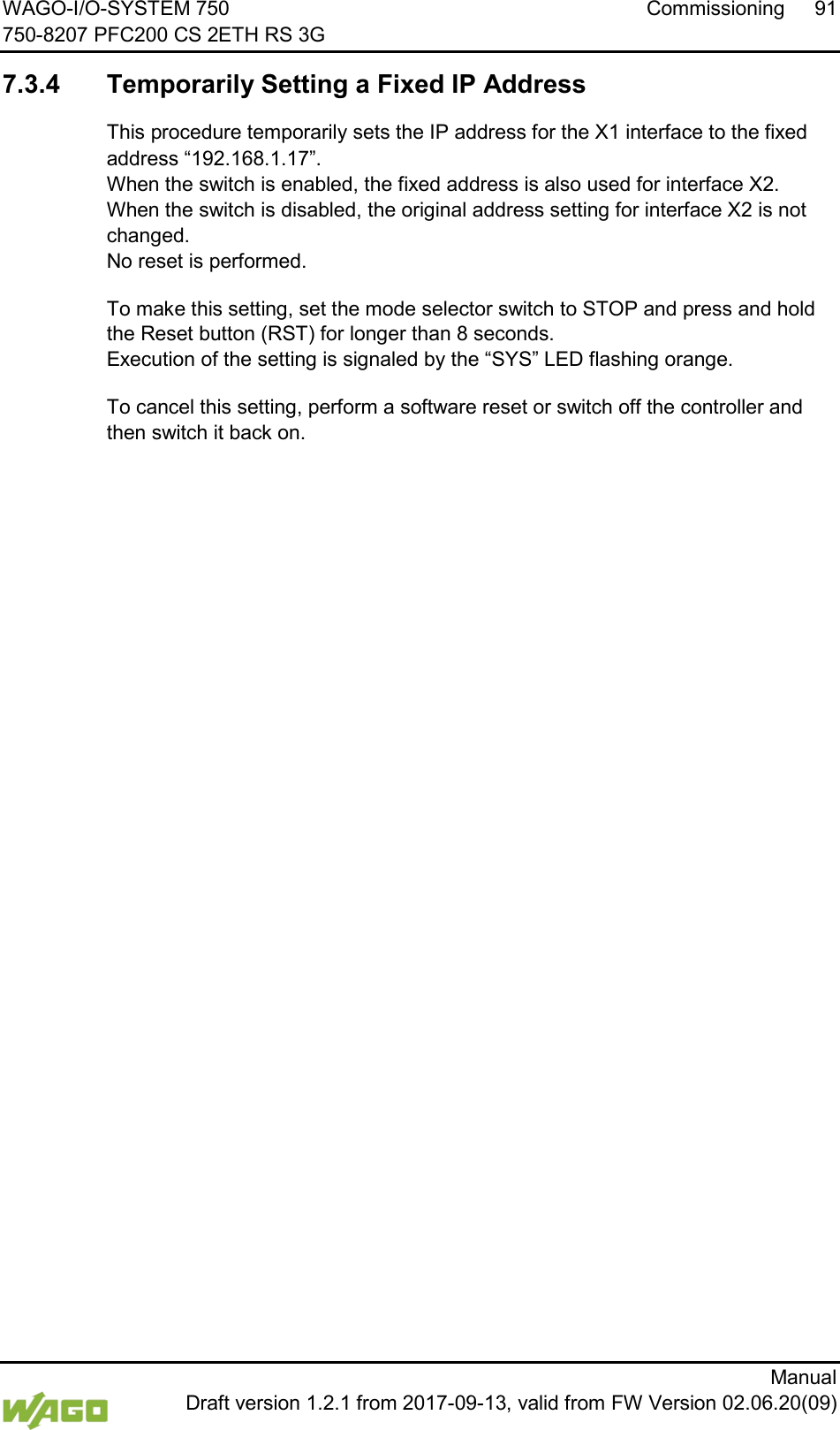
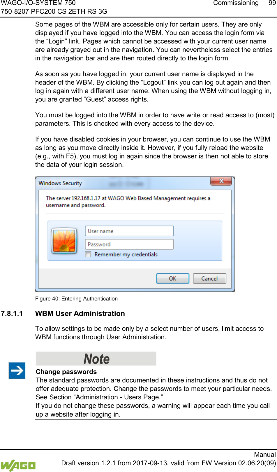
![WAGO-I/O-SYSTEM 750 Commissioning 87 750-8207 PFC200 CS 2ETH RS 3G Manual Draft version 1.2.1 from 2017-09-13, valid from FW Version 02.06.20(09) 4. In the Main menu use the keyboard (arrow keys or numeric keypad) to move to and select Networking and then press [Enter]. Figure 32: CBM – Selecting “Networking” 5. In the Networking menu select TCP/IP and press [Enter]. Figure 33: CBM – Selecting “TCP/IP” 6. In the menu TCP/IP select IP Address and press [Enter]. Figure 34: CBM – Selecting “IP address”](https://usermanual.wiki/WAGO-Kontakttechnik-and-KG/PFC200/User-Guide-3565964-Page-87.png)
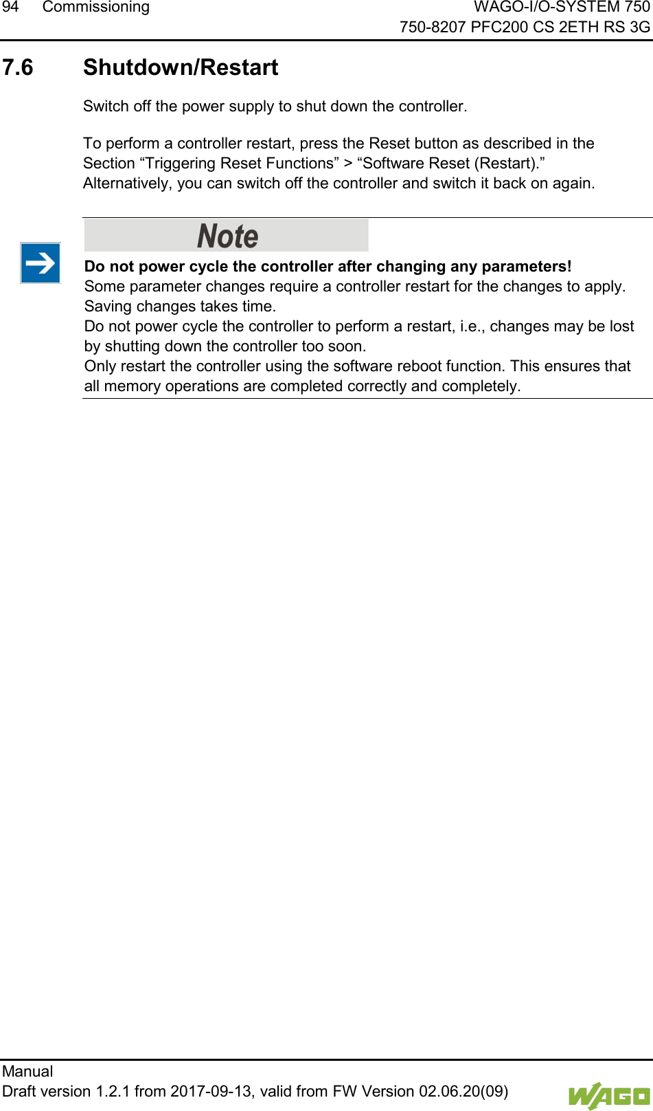
![88 Commissioning WAGO-I/O-SYSTEM 750 750-8207 PFC200 CS 2ETH RS 3G Manual Draft version 1.2.1 from 2017-09-13, valid from FW Version 02.06.20(09) 7. In the menu TCP/IP Configuration select IP Address and press [Enter]. Figure 35: CBM – Selecting the IP Address 8. In the menu Change IP Address enter the new IP address and confirm by clicking [OK]. If you want to return to the main menu without making changes, click [Abort]. Figure 36: CBM – Entering a New IP Address](https://usermanual.wiki/WAGO-Kontakttechnik-and-KG/PFC200/User-Guide-3565964-Page-88.png)
![90 Commissioning WAGO-I/O-SYSTEM 750 750-8207 PFC200 CS 2ETH RS 3G Manual Draft version 1.2.1 from 2017-09-13, valid from FW Version 02.06.20(09) 5. Click [Identify] to read in and identify the connected controller. 6. Select the “Network” tab: Figure 38: “WAGO Ethernet Settings” – “Network” Tab 7. To assign a fixed address, select “Static configuration” on the “Source” line under “Input”. DHCP is normally activated as the default setting. 8. In the column “Input” enter the required IP address and, if applicable, the address of the subnet mask and of the gateway. 9. Click on [Write] to accept the address in the controller. (If necessary, “WAGO Ethernet Settings” will restart your controller. This action may require about 30 seconds.) 10. You can now close “WAGO Ethernet Settings”, or make other changes directly in the Web-based Management system as required. To do this, click on [WBM] at the right in the window.](https://usermanual.wiki/WAGO-Kontakttechnik-and-KG/PFC200/User-Guide-3565964-Page-90.png)
![92 Commissioning WAGO-I/O-SYSTEM 750 750-8207 PFC200 CS 2ETH RS 3G Manual Draft version 1.2.1 from 2017-09-13, valid from FW Version 02.06.20(09) 7.4 Testing the Network Connection Carry out a ping network function to check whether you can reach the controller at the IP address you have assigned in the network. 1. Open the MS DOS prompt window. To do this, enter the command “cmd” in the input field under Start > Execute… > Open: (Windows® XP) or Start > Search programs/files (Windows® 7) and then click [OK] or press [Enter]. 2. In the MS DOS window, enter the command “ping” and the IP address of the controller (for example, ping 192.168.1.17)and then press [Enter]. Host entries in the ARP table! It may also be useful to delete the current host entries in the ARP table with the command “arp -d *” before executing the “ping” command (as administrator in Windows® 7). This ensures that older entries will not impair the success of the “ping” command. 3. Your PC sends out a query that is answered by the controller. This reply appears in the MS DOS prompt window. If the error message “Timeout” appears, the controller has not responded properly. You then need to check your network settings. Figure 39: Example of a Function Test 4. If the test is completed successfully, close the MS DOS window.](https://usermanual.wiki/WAGO-Kontakttechnik-and-KG/PFC200/User-Guide-3565964-Page-92.png)
![WAGO-I/O-SYSTEM 750 Commissioning 93 750-8207 PFC200 CS 2ETH RS 3G Manual Draft version 1.2.1 from 2017-09-13, valid from FW Version 02.06.20(09) 7.5 Changing Standard Passwords Change passwords The standard passwords are documented in these instructions and therefore do not offer adequate protection! Change the passwords to meet your particular needs! To increase security all passwords should contain a combination of lower case letters (a … z), upper case letters (A … Z), numbers (0 … 9), spaces and special characters: (]!"#$%&'()*+,./:;<=>?@[\^_`{|}~-). Passwords should not contain generally known names, dates of birth and other information that is easy to guess. Therefore change the standard passwords before commissioning the controller. Standard passwords are issued for the user groups “WBM Users” and “Linux® Users.” The table in the Section “Function Description” > ... > “Users and Passwords” > “WBM Users Group” shows the standard passwords for the WBM users. Proceed as follows to change these passwords: 1. Connect the controller to a PC via one of the network interfaces (X1, X2). 2. Start a web browser program on the PC and call up the WBM of the controller. 3. Log in on the controller as “admin” user with the standard password. 4. Change the password for all users on the WBM “Configuration of the users for the WBM” page. 5. Select each user and enter a new password and confirm it. The table in the Section “Functional Description” > ... > “Users and Passwords” > “Linux® Users Group” shows the standard passwords for the Linux® users. Proceed as follows to change these passwords: 1. Connect the controller to a PC via the serial interface (X3). 2. Start a terminal program on the PC. 3. Log in on the controller as user “root” with the standard password. 4. Change the password for all users with the “passwd root,” “passwd admin” and “passwd user” commands.](https://usermanual.wiki/WAGO-Kontakttechnik-and-KG/PFC200/User-Guide-3565964-Page-93.png)
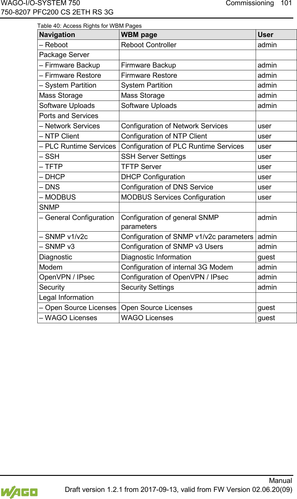
![WAGO-I/O-SYSTEM 750 Commissioning 97 750-8207 PFC200 CS 2ETH RS 3G Manual Draft version 1.2.1 from 2017-09-13, valid from FW Version 02.06.20(09) 7.8 Configuration The following methods are available for configuring the controller: • Access to the Web-based management system via the PC using an Internet browser (“Configuration using Web-Based Management [WBM]”) • Access to the “Console-Based Management” system (CBM) via the PC using a terminal program (via ETHERNET and/or RS-232 interface; “Configuration Using a Terminal Program”) • Access via the CODESYS PLC program using the WagoConfigToolLIB.lib library (“Appendix” > “WagoConfigToolLIB.lib”) • Access via the PC using “WAGO Ethernet Settings” (“Configuration Using ‘WAGO Ethernet Settings’”). The CBM is basically for the initial configuration and startup of the controller. Therefore, it only provides a subset of the WBM parameters. For example, parameters that cannot be displayed in a terminal window in a reasonable way and are not necessary for initial startup are not displayed. You can find the explanations of the parameters starting with the section “‘Information’ Page.”](https://usermanual.wiki/WAGO-Kontakttechnik-and-KG/PFC200/User-Guide-3565964-Page-97.png)
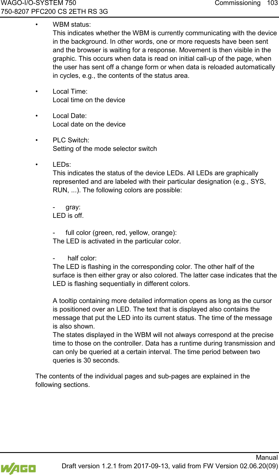
![102 Commissioning WAGO-I/O-SYSTEM 750 750-8207 PFC200 CS 2ETH RS 3G Manual Draft version 1.2.1 from 2017-09-13, valid from FW Version 02.06.20(09) 7.8.1.2 General Information about the Page Figure 42: WBM Browser Window (Example) The device name is displayed in the header of the browser window. When the user has logged out, a [Login] button is displayed on the right in the header line, when logged in a [Logout] button is displayed. The navigation tree is shown on the left of the browser window. You can use this navigation tree to go to the individual pages and, where provided, subpages included in these pages. Some pages can only be called after a successful login. To log in click the [Login] button and enter the user name and password in the login window. A status area with the following elements is displayed on the right: Figure 43: WBM Status Information (Example)](https://usermanual.wiki/WAGO-Kontakttechnik-and-KG/PFC200/User-Guide-3565964-Page-102.png)
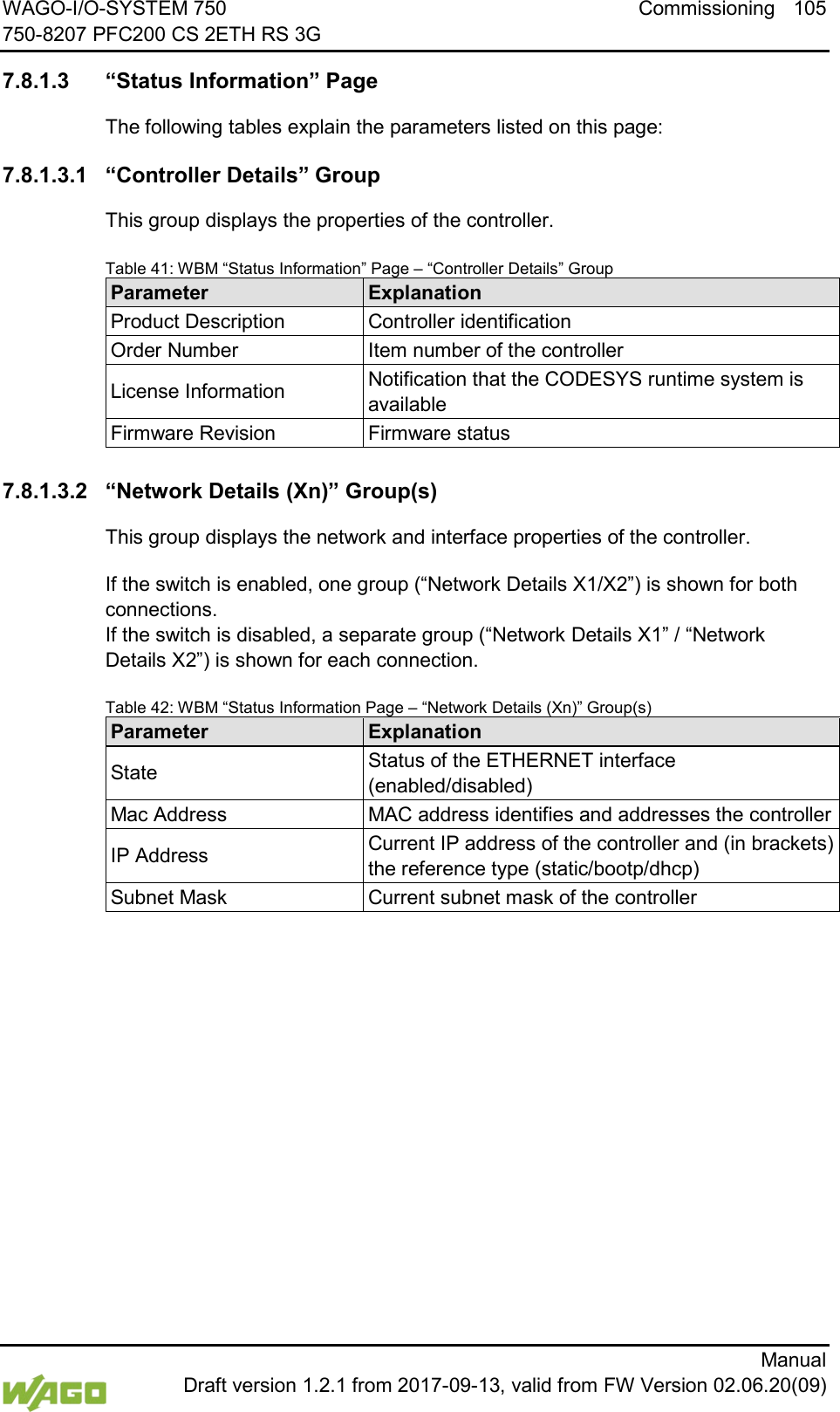
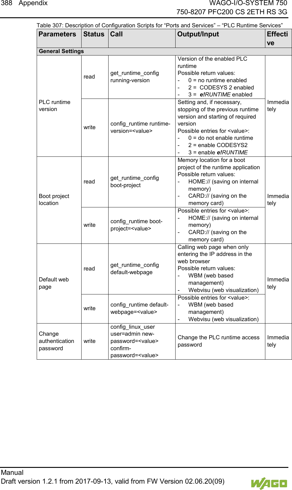
![106 Commissioning WAGO-I/O-SYSTEM 750 750-8207 PFC200 CS 2ETH RS 3G Manual Draft version 1.2.1 from 2017-09-13, valid from FW Version 02.06.20(09) 7.8.1.4 “General PLC Runtime Configuration” Page The settings for the boot project created with the programming software are given on the “General PLC Runtime Configuration” page. 7.8.1.4.1 “General PLC Runtime Configuration” Group Table 43: WBM “General PLC Runtime Configuration” Page – “General PLC Runtime Configuration” Group Parameters Explanation PLC runtime version Select here the PLC runtime system to be enabled. None No runtime system is enabled. CODESYS 2 CODESYS 2 runtime system is enabled. e!RUNTIME e!RUNTIME runtime system is enabled. Home directory on memory card enabled Define if the home directory for the runtime system should be moved to the memory card. Disabled The home directory is stored in the internal memory. Enabled The home directory is moved to the memory card. All data is deleted when switching the runtime system! The runtime system’s home directory is completely deleted when switching the runtime system! Insert a memory card before switching the home directory! When moving the home directory to the memory card, insert a memory card formatted to support file system. Only the first partition of a memory card can be accessed at /media/sd and can be used as the home directory. Perform a reset before switching the home directory! Stop IEC-61131 applications in use before switching the home directory of the runtime system. Restore the device to its initial state using the “Reset” function. Any boot project is deleted. Click [Submit] to apply the change. The runtime system change is effective immediately.](https://usermanual.wiki/WAGO-Kontakttechnik-and-KG/PFC200/User-Guide-3565964-Page-106.png)
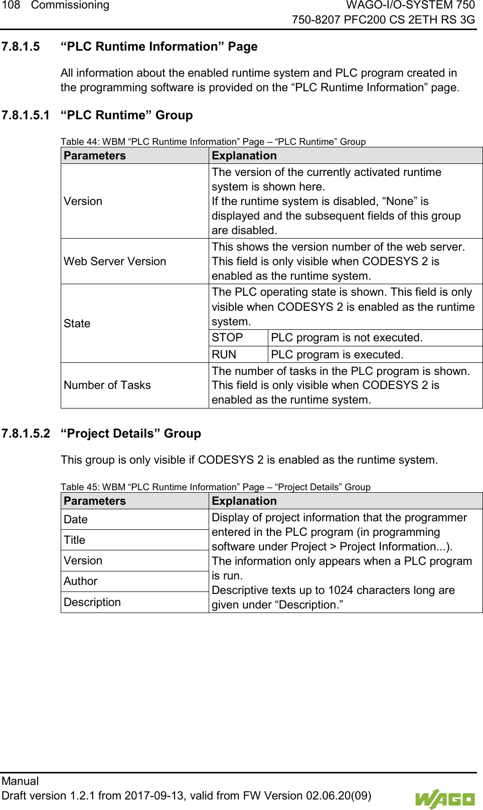
![WAGO-I/O-SYSTEM 750 Commissioning 109 750-8207 PFC200 CS 2ETH RS 3G Manual Draft version 1.2.1 from 2017-09-13, valid from FW Version 02.06.20(09) 7.8.1.5.3 “Task n” Group(s) This group is only visible if CODESYS 2 is enabled as the runtime system. One dedicated group is displayed for each task when the PLC program is executed. As a rule, only the group title is displayed with the task number, the task name and the task ID. Click [+] to expand the group and display the following information. Table 46: WBM “PLC Runtime Information” Page – “Task n” Group(s) Parameters Explanation Cycle count Number of task cycles since the system start Cycle time (µsec) Currently measured task cycle time for the task Cycle time min (µsec) Minimum task cycle time for the task since the system start Cycle time max (µsec) Maximum task cycle time for the task since the system start Cycle time avg (µsec) Average task cycle time since the system start Status Task status (e.g., RUN, STOP) Mode Task execution mode (e.g., in cycles) Priority Set task priority Interval (msec) Set task interval To hide this information, click [–].](https://usermanual.wiki/WAGO-Kontakttechnik-and-KG/PFC200/User-Guide-3565964-Page-109.png)
![110 Commissioning WAGO-I/O-SYSTEM 750 750-8207 PFC200 CS 2ETH RS 3G Manual Draft version 1.2.1 from 2017-09-13, valid from FW Version 02.06.20(09) 7.8.1.6 “PLC WebVisu” Page The settings for the web visualization created in the runtime system are shown on the “PLC WebVisu” page. 7.8.1.6.1 “Web Server Configuration” Group Table 47: WBM “PLC WebVisu” Page – “Web Server Configuration” Group Parameters Explanation CODESYS 2 Webserver State This indicates the status (enabled/disabled) of the CODESYS 2 web server. e!RUNTIME Webserver State This indicates the status (enabled/disabled) of the e!RUNTIME web server. Default Webserver Choose here whether the Web-based Management or web visualization of the runtime system should be displayed when only entering the IP address of the controller. Web-based Management The Web-based Management is displayed. Web-Visu The web visualization of the runtime system is displayed. Click [Submit] to apply change. The change is effective immediately. In its default setting, the WBM is called up when only entering the IP address. To update the display after switching, enter the IP address again in the address line of the web browser. To display the web visualization, the web server must be enabled (in WBM under “Ports and Services” -> “PLC Runtime Services”) and there must be a suitably configured application. Regardless of the default web server setting, the WBM can be called up at any time with “https://<IP address>/wbm” and the web visualization with “https://<IP address>/webvisu.” You can obtain additional information on CODESYS 2 web visualization in the section of the same name. Possible error messages when calling up the web visualization The “500 − Internal Server Error” message indicates that the web server is not enabled. A page with the header “WebVisu not available” means that no application has been loaded in the controller using web visualization.](https://usermanual.wiki/WAGO-Kontakttechnik-and-KG/PFC200/User-Guide-3565964-Page-110.png)
![WAGO-I/O-SYSTEM 750 Commissioning 111 750-8207 PFC200 CS 2ETH RS 3G Manual Draft version 1.2.1 from 2017-09-13, valid from FW Version 02.06.20(09) 7.8.1.7 “Configuration of Host and Domain Name” Page The settings for the general TCP/IP parameters are found on the “Configuration of Host and Domain Name” page. 7.8.1.7.1 “HostName” Group Table 48: WBM “Configuration of Host and Domain Name” Page – “Hostname” Group Parameters Explanation Currently used If you have selected dynamic assignment of an IP address via DHCP, the name of the host currently being used is displayed. Configured Enter here the hostname of your controller to be used if the network interface is changed to a static IP address or if no hostname is transmitted with a DHCP response. Click [Submit] to apply the change. The change is effective immediately. If a hostname is supplied via a DHCP response, this is enabled in the system. If there are several network interfaces with DHCP always the last received hostname is valid. If only the hostname configured here is to be valid, the configuration of the DHCP server must be adapted so that no hostnames are transferred in the DHCP response. 7.8.1.7.2 “Domain Name” Group Table 49: WBM “Configuration of Host and Domain Name” Page – “Domain Name” Group Parameters Explanation Currently used The domain name currently used is displayed. It may differ from the configured domain name if you have selected dynamic assignment of an IP address via DHCP or BootP. Configured Enter the domain name. The default entry is “localdomain.lan”. Click [Submit] to apply the change. The change is effective immediately. If a domain name is supplied via a DHCP response, this is enabled in the system. If there are several network interfaces with DHCP, the last received domain name is always valid. If only the domain name configured here is to be valid, the configuration of the DHCP server must be adapted so that no domain names are transferred in the DHCP response.](https://usermanual.wiki/WAGO-Kontakttechnik-and-KG/PFC200/User-Guide-3565964-Page-111.png)
![112 Commissioning WAGO-I/O-SYSTEM 750 750-8207 PFC200 CS 2ETH RS 3G Manual Draft version 1.2.1 from 2017-09-13, valid from FW Version 02.06.20(09) </dg_ 7.8.1.8 “TCP/IP Configuration” Page The TCP/IP settings for the ETHERNET interfaces are shown on the “TCP/IP configuration” page. 7.8.1.8.1 “IP Configuration (Xn)” Group(s) If the switch is enabled, one group (“IP Configuration”) is shown for both connections. If the switch is disabled, a separate group (“IP Configuration X1” / “IP Configuration X2”) is shown for each connection. Table 50: WBM “TCP/IP Configuration” Page – “IP Configuration (Xn)” Group(s) Parameters Explanation Configuration Type Select a static or dynamic IP address. Static IP Static IP addressing DHCP Dynamic IP addressing BootP Dynamic IP addressing IP Address Enter here a static IP address. This is enabled if “Static IP” is enabled in the Configuration Type field. Subnet Mask Enter the subnet mask. This is enabled if “Static IP” is enabled in the Configuration Type field. Click [Submit] to apply changes. The changes are effective immediately.](https://usermanual.wiki/WAGO-Kontakttechnik-and-KG/PFC200/User-Guide-3565964-Page-112.png)
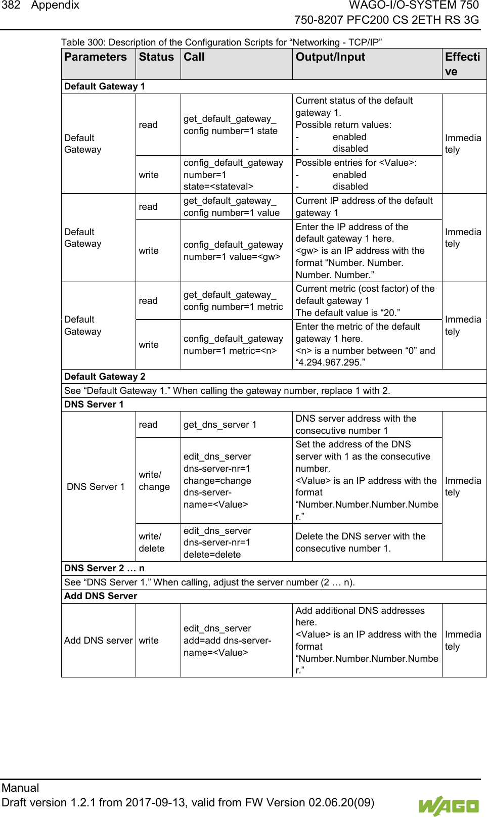
![WAGO-I/O-SYSTEM 750 Commissioning 113 750-8207 PFC200 CS 2ETH RS 3G Manual Draft version 1.2.1 from 2017-09-13, valid from FW Version 02.06.20(09) 7.8.1.8.2 “Default Gateway n” Groups You can configure two default gateways. The controller transmits all network data not going to a station on the local network to a default gateway. First the gateway with the lowest metric is addressed. If this is not reached, the second gateway is used. The selection is random if the metric is the same. A default gateway can also be configured via DHCP. These default gateways are given the metric 10, by which they are normally used before the static gateways. Table 51: WBM “TCP/IP Configuration” Page – “Default Gateway n” Group Parameters Explanation Gateway enabled Set here whether the selected default gateway is to be used. Disabled The default gateway is not used. Enabled The default gateway is used. Destination Address Enter here if any network devices or only a specific network device or device pool is to be accessed. “default” Any network devices can be reached. Network address Only a specific network device or device from the set address pool can be reached. Destination Mask Enter the subnet mask of the station. If “default” is entered at Destination Address, the value “0.0.0.0” must be entered here. Gateway Address Enter the address of the default gateway. Gateway Metric Set here a number as the metric. With multiple default gateways, the metric defines the gateway to which data packets are first sent. Priority is given to the gateway with the lower metric. The default value for the metric is 20. The lowest value is 0. The highest value is 4.294.967.295. Click [Submit] to apply the change. The change is effective immediately.](https://usermanual.wiki/WAGO-Kontakttechnik-and-KG/PFC200/User-Guide-3565964-Page-113.png)
![114 Commissioning WAGO-I/O-SYSTEM 750 750-8207 PFC200 CS 2ETH RS 3G Manual Draft version 1.2.1 from 2017-09-13, valid from FW Version 02.06.20(09) 7.8.1.8.3 “DNS Server” Group Table 52: WBM “TCP/IP Configuration” Page – “DNS Server” Group Parameters Explanation Configured: None/ DNS Server n The addresses of the defined DNS servers are displayed. If no server has been defined, “Configured: None” is displayed. New Server IP Add additional DNS addresses. You can enter 10 addresses. Additionally used (assigned by DHCP) The DNS servers assigned if necessary by DHCP (or BootP) are displayed. If no DNS server has been assigned by DHCP (or BootP), “none” is displayed. Click [Delete] to remove the selected DNS server. The change is effective immediately. Click [Add] to add the entered DNS server. The change is effective immediately.](https://usermanual.wiki/WAGO-Kontakttechnik-and-KG/PFC200/User-Guide-3565964-Page-114.png)
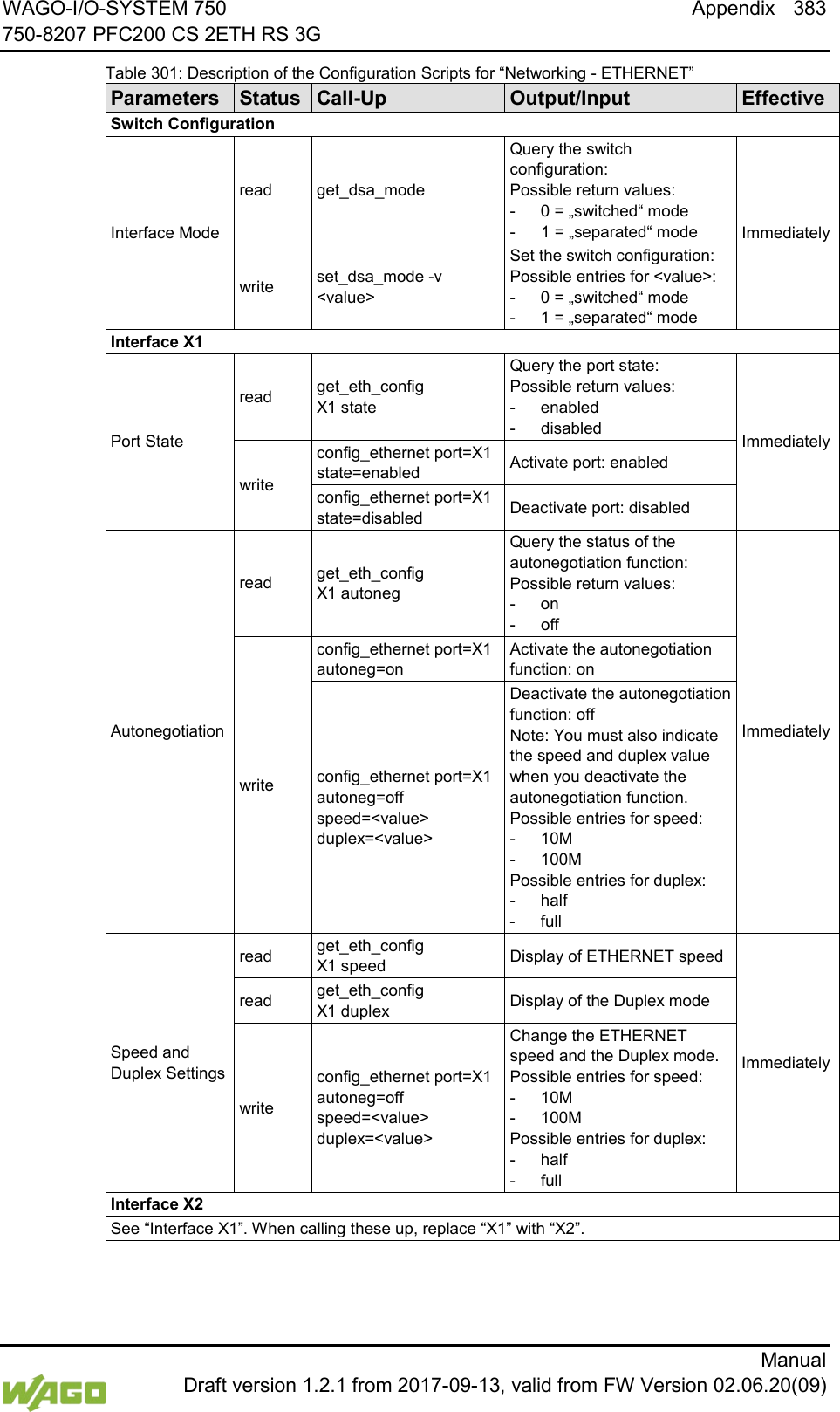
![WAGO-I/O-SYSTEM 750 Commissioning 115 750-8207 PFC200 CS 2ETH RS 3G Manual Draft version 1.2.1 from 2017-09-13, valid from FW Version 02.06.20(09) 7.8.1.9 “Ethernet Configuration” Page The settings for Ethernet TCP/IP are located on the “Ethernet Configuration” page. 7.8.1.9.1 “Switch Configuration” Group Table 53: WBM “Ethernet Configuration” Page – “Switch Configuration” Group Parameter Explanation Interfaces Enable or disable the switch. Switched Both interfaces are operated with one IP address. Separated Each interface is operated with its own IP address. Port Mirror Enable or disable the mirroring of the data traffic between the ports. None Both Ethernet ports operating normally. X1 The entire data traffic between X1 and the PFC system is mirrored at port X2. X2 The entire data traffic between X2 and the PFC system is mirrored at port X1. Fast Aging enabled Set here the aging time of unused entries in the list of MAC addresses with a port assignment to external network stations. Disabled An unused address entry becomes obsolete after 200 seconds. Enabled An unused address entry becomes obsolete after 800 microseconds. Broadcast Protection Set here the broadcast limit for protection against overloads. Disabled No limitation of broadcast packets. 1 % ... 5 % Limitation of incoming broadcast packets to the selected percentage of the total possible data throughput (10/100Mbit). Rate Limit Set here the basic limitation of the incoming data traffic. Disabled No limitation of the incoming data traffic 64 kbps … 99 mbps Limitation of the incoming data traffic to the entered value Click [Submit] to apply the change. The change is effective immediately. 7.8.1.9.2 “Interface Xn” Groups One group (“Interface X1” / “Interface X2”) is displayed for each connection.](https://usermanual.wiki/WAGO-Kontakttechnik-and-KG/PFC200/User-Guide-3565964-Page-115.png)
![116 Commissioning WAGO-I/O-SYSTEM 750 750-8207 PFC200 CS 2ETH RS 3G Manual Draft version 1.2.1 from 2017-09-13, valid from FW Version 02.06.20(09) Table 54: WBM “Ethernet Configuration” Page – “Interface Xn” Groups Parameter Explanation Enabled You can enable or disable the interface. Autonegotiation on When Autonegotiation is enabled, the connection modalities are negotiated automatically with the peer devices. Speed/Duplex Select the transmission speed and the duplex method: 10 Mbit half-duplex Information can only be sent or received. 100 Mbit half-duplex 10 Mbit full-duplex Information can be sent and received simultaneously. 100 Mbit full-duplex Click [Submit] to apply changes. The changes are effective immediately.](https://usermanual.wiki/WAGO-Kontakttechnik-and-KG/PFC200/User-Guide-3565964-Page-116.png)
![WAGO-I/O-SYSTEM 750 Commissioning 117 750-8207 PFC200 CS 2ETH RS 3G Manual Draft version 1.2.1 from 2017-09-13, valid from FW Version 02.06.20(09) 7.8.1.10 “General Firewall Configuration” Page 7.8.1.10.1 “Global Firewall Parameters” Group Table 55: WBM “General Firewall Configuration” Page – “Global Firewall Parameters” Group Parameters Explanation Firewall enabled entirely Enables/disables the complete functionality of the firewall. This setting has the highest priority. If the firewall is disabled, all other settings have no direct effect. The configuration of the other parameters is possible nevertheless so that you can set the firewall parameters correctly before you enable the firewall. ICMP echo broadcast protection Enable or disable the “ICMP echo broadcast” protection. Max. UDP connections per second You can specify the maximum number of UDP connections per second. Max. TCP connections per second You can specify the maximum number of TCP connections per second. Click [Submit] to apply the change. The change is effective immediately.](https://usermanual.wiki/WAGO-Kontakttechnik-and-KG/PFC200/User-Guide-3565964-Page-117.png)
![118 Commissioning WAGO-I/O-SYSTEM 750 750-8207 PFC200 CS 2ETH RS 3G Manual Draft version 1.2.1 from 2017-09-13, valid from FW Version 02.06.20(09) 7.8.1.10.2 “Firewall Parameters Interface xxx” Group These settings in this group refer to the configuration of the firewall at IP level. Table 56: WBM “General Firewall Configuration” Page – “Firewall Parameter Interface Xn” Group Parameters Explanation Firewall enabled for Interface Enable or disable the firewall for the specific interface. ICMP echo protection Enable or disable the “ICMP echo” protection for the respective interface. ICMP echo limit per second You can specify the maximum number of “ICMP echo bursts” per second. ICMP burst limit (0 = disabled) You can specify the maximum number of “ICMP echo bursts” per second. “0” = “Disabled” Service enabled Telnet Enable or disable the firewall for the respective service. The services themselves must be enabled or disabled separately on the “Ports and Services” page. FTP FTPS HTTP HTTPS I/O-CHECK PLC Runtime PLC WebVisu – direct link (port 8080) SSH TFTP BootP/DHCP DNS MODBUS TCP MODBUS UDP SNMP Click [Submit] to apply the change. The change is effective immediately.](https://usermanual.wiki/WAGO-Kontakttechnik-and-KG/PFC200/User-Guide-3565964-Page-118.png)
![WAGO-I/O-SYSTEM 750 Commissioning 119 750-8207 PFC200 CS 2ETH RS 3G Manual Draft version 1.2.1 from 2017-09-13, valid from FW Version 02.06.20(09) </dg_ 7.8.1.11 “Configuration of MAC Address Filter” Page You set the firewall configuration at ETHERNET level on this page. The “MAC Address Filter Whitelist” contains a default entry with the following values: MAC address: 00:30:DE:00:00:00 MAC mask: ff:ff:ff:00:00:00 If you enable the default entry, this already allows communication between different WAGO devices in the network. Enable the MAC address filter before activation! Before activating the MAC address filter, you must enter and activate your own MAC address in the “MAC Address Filter Whitelist.” Otherwise you cannot access the device via the ETHERNET. This also applies to other services that are used by your device, e.g., the IP configuration via DHCP. If the “MAC Address Filter Whitelist” does not contain the MAC address of your DHCP server, your device will lose its IP settings after the next refresh cycle and is then no longer accessible. If the “MAC Address Filter Whitelist” does not contain an entry, the activation of the filter is prevented. If at least one activated address is entered, you will receive an appropriate warning before activation, which you have to acknowledge. The check described above is only performed in the WBM but not in the CBM! 7.8.1.11.1 “Global MAC Address Filter State” Group Table 57: WBM “Configuration of MAC Address Filter” Page – “Global MAC Address Filter State” Group Parameters Explanation Filter enabled Enable or disable the global MAC address filter here. Click [Submit] to apply change. The change is effective immediately.](https://usermanual.wiki/WAGO-Kontakttechnik-and-KG/PFC200/User-Guide-3565964-Page-119.png)
![120 Commissioning WAGO-I/O-SYSTEM 750 750-8207 PFC200 CS 2ETH RS 3G Manual Draft version 1.2.1 from 2017-09-13, valid from FW Version 02.06.20(09) 7.8.1.11.2 “MAC Address Filter State Xn” Group Table 58: WBM “Configuration of MAC Address Filter” Page – “MAC Address Filter State Xn” Group Parameters Explanation Filter enabled Enable or disable here the MAC address filter for the specific interface. Click [Submit] to apply change. The change is effective immediately. 7.8.1.11.3 “MAC Address Filter Whitelist” Group Table 59: WBM “Configuration of MAC Address Filter” Page – “MAC Address Filter Whitelist” Group Parameters Explanation MAC address Displays the MAC address of the relevant list entry. MAC mask This displays the MAC mask of the relevant list entry. Filter enabled Enable or disable the filter for the relevant list entry here. … MAC address Enter here the MAC address for a new list entry. You can enter 10 filters. MAC mask Enter the MAC mask for the new list entry here. Filter enabled Enable or disable the filter for the new list entry here. Click [Submit] to apply the change. The change is effective immediately. Click the appropriate [Delete] button to remove an existing list entry. The change is effective immediately. Click [Add] to accept a new list entry. You can enter 10 filters. The change is effective immediately.](https://usermanual.wiki/WAGO-Kontakttechnik-and-KG/PFC200/User-Guide-3565964-Page-120.png)
![WAGO-I/O-SYSTEM 750 Commissioning 121 750-8207 PFC200 CS 2ETH RS 3G Manual Draft version 1.2.1 from 2017-09-13, valid from FW Version 02.06.20(09) 7.8.1.12 “Configuration of User Filter” Page 7.8.1.12.1 “User Filter” Group Table 60: WBM “Configuration of User Filter” Page – “User Filter” Group Parameters Explanation Count The number of configured user filters is displayed. 7.8.1.12.2 “User Filter n” Group Table 61: WBM “Configuration of User Filter” Page – “User Filter n” Group Parameters Explanation Source IP address The source IP address for the respective filter entry is displayed. Source netmask This displays the source network for the corresponding filter entry. Source port The source port number for the respective filter entry is displayed. Destination IP address The destination IP address for the respective filter entry is displayed. Destination subnet mask The destination network mask for the respective filter entry is displayed. Destination port The designation port number for the respective filter entry is displayed. Protocol The permitted protocols for the respective filter is displayed. Input interface The permitted interfaces for the respective filter are displayed. Policy Hier wird angezeigt, ob der Netzwerkteilnehmer durch den Filter zugelassen oder ausgeschlossen ist. Click the appropriate [Delete] button to remove a configured filter. The change is effective immediately.](https://usermanual.wiki/WAGO-Kontakttechnik-and-KG/PFC200/User-Guide-3565964-Page-121.png)
![122 Commissioning WAGO-I/O-SYSTEM 750 750-8207 PFC200 CS 2ETH RS 3G Manual Draft version 1.2.1 from 2017-09-13, valid from FW Version 02.06.20(09) 7.8.1.12.3 “Add New User Filter” Group You can enter 10 filters. You only have to enter values in the fields that are to be set for the filter. At least one value must be entered, all other fields can remain empty. Table 62: WBM “Configuration of User Filter” Page – “Add New User Filter” Group Parameters Explanation Policy Select here whether the network devices is to be allowed or excluded by the filter. Allow The network device is permitted. Drop The network device is excluded. Source IP address Enter here the source IP address for the new filter entry. Source netmask Enter here the source network mask for the new filter entry. Source port Enter here the source port address for the new filter entry. Destination IP address Enter here the destination IP address for the new filter entry. Destination subnet mask Enter here the destination network mask for the new filter entry. Destination port Enter the destination port number for the new filter entry. Protocol Enter here the permitted protocols for the new filter. TCP The TCP service is permitted. UDP The UDP service is permitted. Input interface Enter here the permitted interfaces for the new filter. X1 The X1 interface is permitted. X2 The X2 interface is permitted. VPN The VPN interface is permitted. To accept the new filter click [Add]. The change is effective immediately.](https://usermanual.wiki/WAGO-Kontakttechnik-and-KG/PFC200/User-Guide-3565964-Page-122.png)
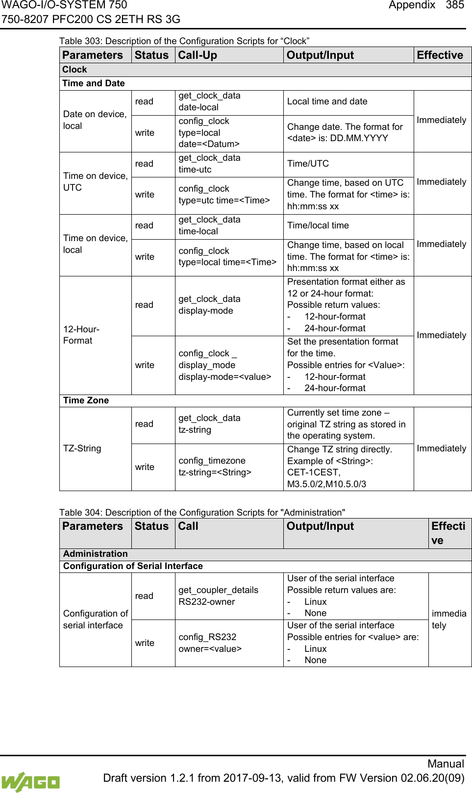
![WAGO-I/O-SYSTEM 750 Commissioning 123 750-8207 PFC200 CS 2ETH RS 3G Manual Draft version 1.2.1 from 2017-09-13, valid from FW Version 02.06.20(09) 7.8.1.13 “Configuration of Time and Date” Page The settings for date and time are shown on the “Configuration of Time and Date” page. 7.8.1.13.1 “Date on Device” Group Table 63: WBM “Configuration of Time and Date” Page – “Date on Device” Group Parameters Explanation Local Set date. Click [Change date] to apply change. The change is effective immediately. 7.8.1.13.2 “Time on Device” Group Table 64: WBM “Configuration of Time and Date” Page – “Time on Device” Group Parameters Explanation Local Set local time. UTC Set GMT time. 12 h format For switching between 12-hour and 24-hour time display Click [Change time] to apply change to the time. The change is effective immediately. Click [Change format] to apply change to the time format. The change is effective immediately.](https://usermanual.wiki/WAGO-Kontakttechnik-and-KG/PFC200/User-Guide-3565964-Page-123.png)
![124 Commissioning WAGO-I/O-SYSTEM 750 750-8207 PFC200 CS 2ETH RS 3G Manual Draft version 1.2.1 from 2017-09-13, valid from FW Version 02.06.20(09) 7.8.1.13.3 “Time Zone” Group You can specify the appropriate time zone for your location in this group. The total number of possible time zones is over 500. A complete listing would exceed the scope of this documentation. Due to the large number of time zones, the selection is limited via the “Time Zone” parameter. You can select further time zones with the “TZ String” parameter. Table 65: WBM “Configuration of Time and Date” Page – “Time Zone” Group Parameters Explanation Time zone Specify the appropriate time zone for your location. AST/ADT “Atlantic Standard Time,” Halifax EST/EDT “Eastern Standard Time,” New York, Toronto CST/CDT “Central Standard Time,” Chicago, Winnipeg MST/MDT “Mountain Standard Time,” Denver, Edmonton PST/PDT “Pacific Standard Time,” Los Angeles, Whitehouse: GMT/BST Greenwich Mean Time,” GB, P, IRL, IS, … CET/CEST* “Central European Time,” B, DK, D, F, I, CRO, NL, … EET/EEST “Eastern European Time,” BUL, FI, GR, TR, … CST “China Standard Time” JST “Japan/Korea Standard Time” * Default setting Click [Change] to apply time zone change. The change is effective immediately.](https://usermanual.wiki/WAGO-Kontakttechnik-and-KG/PFC200/User-Guide-3565964-Page-124.png)
![WAGO-I/O-SYSTEM 750 Commissioning 125 750-8207 PFC200 CS 2ETH RS 3G Manual Draft version 1.2.1 from 2017-09-13, valid from FW Version 02.06.20(09) 7.8.1.13.4 “TZ String” Group In this group you can enter a time zone that is not contained in the “Time Zone” selection. If the controller can associate the TZ string entered with a known time zone that had been missing from the “Time Zone” selection, this time zone is then also added to the “Time Zone” list. You can find information on time zones and the corresponding “TZ strings” on the Internet. For example, to indicate the pure UTC time, enter the TZ string “UTC0.” If no unique association is possible, the text “Unknown” is displayed for the “Time Zone” selection. Table 66: WBM “Configuration of Time and Date” Page – “TZ String” Group Parameters Explanation TZ string You can enter the name of the time zone or the country and city here. Click [Change] to apply the change. The change is effective immediately.](https://usermanual.wiki/WAGO-Kontakttechnik-and-KG/PFC200/User-Guide-3565964-Page-125.png)
![126 Commissioning WAGO-I/O-SYSTEM 750 750-8207 PFC200 CS 2ETH RS 3G Manual Draft version 1.2.1 from 2017-09-13, valid from FW Version 02.06.20(09) </dg_ 7.8.1.14 “Configuration of the Users for the Web-based Management” Page The settings for user administration are shown on this page. 7.8.1.14.1 “Change Password for Selected User” Group Change passwords Default passwords are documented in these instructions and therefore do not offer adequate protection! Change the passwords to meet your particular needs. Table 67: WBM “Configuration of the users for the Web-based Management” Page – “Change Password for Selected User” Group Parameters Explanation Select User Select the user (“user” or “admin”) for new password assignment. New Password Enter the new password for the user selected under “Select User”. The following ASCII characters for passwords are valid: a … z, A … Z, 0 … 9 and spaces. These special characters are also valid: ]!"#$%&'()*+,./:;<=>?@[\^_`{|}~- Confirm password Enter the new password again for confirmation. Click [Change Password] to apply change. The change is effective immediately. Observe the valid characters for WBM passwords! If WBM passwords with invalid characters are set outside the WBM system (e.g. via CBM), then accessing the WBM pages is no longer possible! Observe access rights Authorized WBM users only have access to the Web pages. User administration for controller applications is configured separately.](https://usermanual.wiki/WAGO-Kontakttechnik-and-KG/PFC200/User-Guide-3565964-Page-126.png)
![WAGO-I/O-SYSTEM 750 Commissioning 127 750-8207 PFC200 CS 2ETH RS 3G Manual Draft version 1.2.1 from 2017-09-13, valid from FW Version 02.06.20(09) </dg_ 7.8.1.15 “Create Bootable Image” Page You can create a bootable image on the “Create Bootable Image” page. 7.8.1.15.1 "Create Bootable Image from Active Partition (<Active Partition>" Group The active partition that boot-up was performed from is displayed in brackets in the heading. Table 68: WBM “Create Bootable Image” page – “Create bootable image from active partition” Group Parameters Explanation Destination The possible destination partition that an image will be saved to is displayed. Depending on which medium has been booted, the following destination is available for selection after boot-up for the image to be generated: System was booted from Target partition for “bootable image” Memory Card Internal Flash Internal memory Memory Card Size of created image Define the size of the image on the memory card. This field is only visible when “Memory Card” is set as the target. Reduced to content The storage space of the copied image is kept as small as possible. Full card size The image is created so that the entire memory card is filled. Once the destination has been determined and output, it is then checked and the results of this check are displayed below the settings: - Free space on target device: If the available memory space is less than 5% a warning is displayed. You can still start the copy process despite the warning. If the available space is definitively too low, a corresponding message is displayed and copying cannot be started. - Device being used by CODESYS: If the device is being used by CODESYS a warning is displayed. Although it is not recommended, you can still start the copying procedure despite this warning. Click [Start Copy] to start the copying procedure. If the outcome of the test is positive, copying begins immediately. If errors have been detected, a corresponding message is displayed and copying is not started. If warnings have been issued, these are displayed again and you must then confirm that you still wish to continue.](https://usermanual.wiki/WAGO-Kontakttechnik-and-KG/PFC200/User-Guide-3565964-Page-127.png)
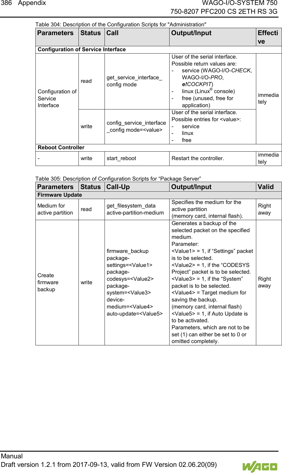
![WAGO-I/O-SYSTEM 750 Commissioning 129 750-8207 PFC200 CS 2ETH RS 3G Manual Draft version 1.2.1 from 2017-09-13, valid from FW Version 02.06.20(09) </dg_ 7.8.1.16 “Configuration of Serial Interface RS232” Page The settings for the serial interface are shown on the “Configuration of Serial Interface RS232” page. 7.8.1.16.1 “Serial Interface Assigned to” Group The application that the serial interface is currently assigned to is displayed. 7.8.1.16.2 “Assign Owner of Serial Interface (Active after Next Controller Reboot)” Group You can specify the application that the serial interface is assigned to after the next controller reboot. Table 69: WBM “Configuration of Serial Interface RS232” Page – “Assign Owner of Serial Interface” Group Parameters Explanation Linux® Console Specify that the serial interface is assigned to the Linux® console. Unassigned (usage by applications, libraries, CODESYS) Specify that the serial interface is not to be assigned to any particular application and is available, so that the CODESYS program, for example, can access it via function blocks. Remove RS-485 devices before switching to “Linux Console”! Connected RS-485 devices can be damaged when switching to “Linux Console”. Remove these devices before switching! Click [Change Owner] to apply the change. The change only takes effect after restarting the controller. For this purpose, use the WBM reboot function. Do not shut down the controller too early!](https://usermanual.wiki/WAGO-Kontakttechnik-and-KG/PFC200/User-Guide-3565964-Page-129.png)
![130 Commissioning WAGO-I/O-SYSTEM 750 750-8207 PFC200 CS 2ETH RS 3G Manual Draft version 1.2.1 from 2017-09-13, valid from FW Version 02.06.20(09) 7.8.1.17 “Configuration of Service Interface” Page The settings for the service interface are shown on the “Configuration of the Service Interface” page. 7.8.1.17.1 “Service Interface assigned to” Group The application that the service interface is currently assigned to is displayed. 7.8.1.17.2 “Assign Owner of Service Interface (enabled after next controller reboot)” Group You can specify the application to which the service interface is assigned after the next controller reboot. Table 70: WBM “Configuration of Serial Interface RS-232” page – “Assign Owner of Service Interface” Group Parameters Explanation WAGO Service Communication Specify that the service interface is used for the WAGO Service communication or runtime system communication. Linux® Console Specify that the service interface is assigned to the Linux® console. Unassigned (usage by applications, libraries, CODESYS) Specify that the service interface is not to be assigned to any application and is available, so that the CODESYS program, for example, can access it via function blocks. Click [Change Owner] to apply the change. The changes only take effect after restarting the controller. For this purpose, use the WBM reboot function. Do not shut down the controller too early!](https://usermanual.wiki/WAGO-Kontakttechnik-and-KG/PFC200/User-Guide-3565964-Page-130.png)
![WAGO-I/O-SYSTEM 750 Commissioning 131 750-8207 PFC200 CS 2ETH RS 3G Manual Draft version 1.2.1 from 2017-09-13, valid from FW Version 02.06.20(09) </dg_ 7.8.1.18 “Reboot Controller” Page The settings for the system reboot are shown on the “Reboot Controller” page. 7.8.1.18.1 “Reboot Controller” Group Click the [Reboot] button to reboot the system. Account for boot-up time! The boot process takes time. You cannot access the controller while this is occurring.](https://usermanual.wiki/WAGO-Kontakttechnik-and-KG/PFC200/User-Guide-3565964-Page-131.png)
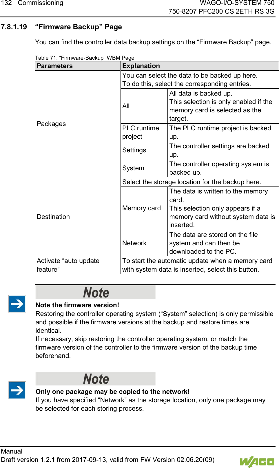
![WAGO-I/O-SYSTEM 750 Commissioning 133 750-8207 PFC200 CS 2ETH RS 3G Manual Draft version 1.2.1 from 2017-09-13, valid from FW Version 02.06.20(09) No backup of the memory card! Backup from the memory card to the internal flash memory is not possible. Account for backup time Generation of backup files can take several minutes. Stop the CODESYS program before you start the backup procedure to help shorten the time required. To begin the backup procedure, click the [Submit] button.](https://usermanual.wiki/WAGO-Kontakttechnik-and-KG/PFC200/User-Guide-3565964-Page-133.png)
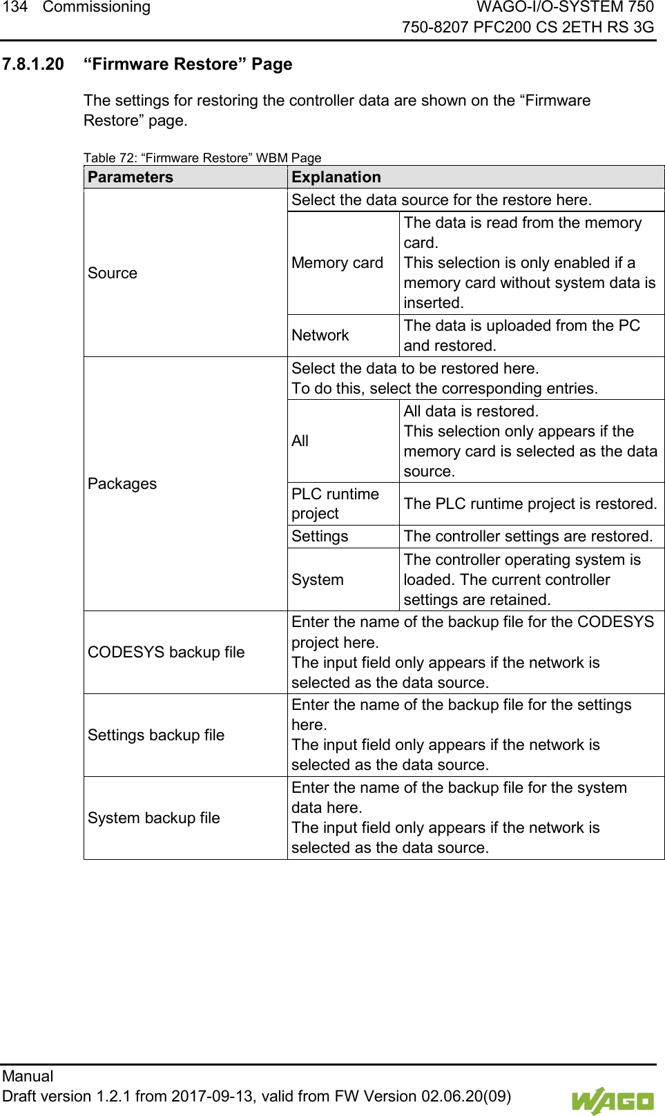
![WAGO-I/O-SYSTEM 750 Commissioning 135 750-8207 PFC200 CS 2ETH RS 3G Manual Draft version 1.2.1 from 2017-09-13, valid from FW Version 02.06.20(09) Note the firmware version! Restoring the controller operating system (“System” selection) is only permissible and possible if the firmware versions at the backup and restore times are identical. If necessary, skip restoring the controller operating system, or match the firmware version of the controller to the firmware version of the backup time beforehand. Restoration only possible from internal memory! If the device was booted from the memory card, the firmware cannot be restored. Reset by restore A reset is performed when the system or settings are restored by CODESYS! Connection loss through restore If the restore changes the parameters of the ETHERNET connection, the WBM may then no longer be able to open a connection to the device. You must call the WBM again by entering the correct IP address of the device in the address line. Click the [Browse] button to select the files in Explorer. The buttons only appear if the network is selected as the data source. To start the restore procedure, click the [Submit] button.](https://usermanual.wiki/WAGO-Kontakttechnik-and-KG/PFC200/User-Guide-3565964-Page-135.png)
![136 Commissioning WAGO-I/O-SYSTEM 750 750-8207 PFC200 CS 2ETH RS 3G Manual Draft version 1.2.1 from 2017-09-13, valid from FW Version 02.06.20(09) </dg_ 7.8.1.21 “System Partition” Page The settings for specifying the partition that the system will be started from are shown on the “System Partition” page. 7.8.1.21.1 “Current Active Partition” Group The partition currently in use is displayed here. 7.8.1.21.2 “Set Inactive Partition Active” Group Click [Activate Partition] to start the system from a different partition at the next controller reboot. Ensure bootable partition! A functional firmware backup must be present in the boot partition!](https://usermanual.wiki/WAGO-Kontakttechnik-and-KG/PFC200/User-Guide-3565964-Page-136.png)
![WAGO-I/O-SYSTEM 750 Commissioning 137 750-8207 PFC200 CS 2ETH RS 3G Manual Draft version 1.2.1 from 2017-09-13, valid from FW Version 02.06.20(09) </dg_ 7.8.1.22 “Mass Storage” Page A group containing information about the storage volume is displayed for each storage volume that is found, along with an additional group for formatting (when this is possible). The group title contains the designation for the storage volume (“SD card” or “Internal Flash”) and, if this storage volume is also the active partition, the text “Active Partition”. 7.8.1.22.1 “<Device Name>” Group(s) Table 73: WBM “Mass Storage” Page – “<Device Name>” Group Parameters Explanation Device The name of the storage volume in the operating system file system is displayed here. Volume name The name of the storage volume is displayed here. 7.8.1.22.2 “<Device Name> - FAT Format” Group(s) Table 74: WBM “Mass Storage” Page – “<Device Name>” Group Parameters Explanation Volume Name Specify the name for the storage volume when formatted. Data are deleted! Any data stored in the storage volume is deleted during formatting! To format the specified storage volume, click [Start Formatting].](https://usermanual.wiki/WAGO-Kontakttechnik-and-KG/PFC200/User-Guide-3565964-Page-137.png)
![138 Commissioning WAGO-I/O-SYSTEM 750 750-8207 PFC200 CS 2ETH RS 3G Manual Draft version 1.2.1 from 2017-09-13, valid from FW Version 02.06.20(09) </dg_ 7.8.1.23 “Software Uploads” Page The settings for a device update are shown on the “Software Uploads” page. 7.8.1.23.1 “Upload New Software” Group Table 75: WBM “Software Uploads” Page – “Upload New Software” Group Parameter Explanation Software Files You can select fieldbus software, program licenses and update scripts, for example, for transfer from a PC to the controller. To select a file on the PC, click the [Browse] button. To transfer the selected file to the controller, click [Start Upload] button. 7.8.1.23.2 “Activate New Software” Group Table 76: WBM “Software Uploads” Page – “Activate New Software” Group Parameter Explanation Software File This shows the file name of the transferred software package. If no new uploaded software package is present on the controller, the message “No upload file exists” is displayed. Action Select here the action required. Activate The transferred software package is activated. Force (Manual reboot afterwards needed) Installs a transferred software package that cannot be activated with “Activate.” Required for activating a controller reboot. The software package is activated on reboot. Discard (delete upload) The transferred software package is deleted again by the controller. To perform the action, click the [Submit] button. The process starts immediately. The file with the software package is deleted again after the installation is completed or when the controller is restarted.](https://usermanual.wiki/WAGO-Kontakttechnik-and-KG/PFC200/User-Guide-3565964-Page-138.png)
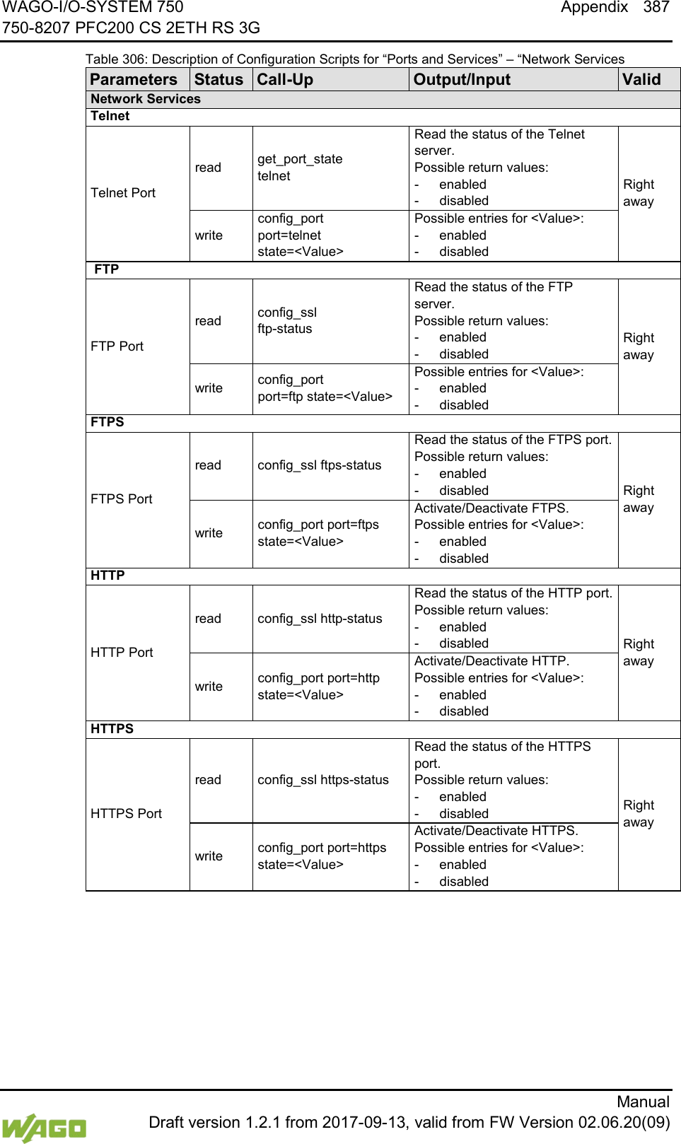
![WAGO-I/O-SYSTEM 750 Commissioning 139 750-8207 PFC200 CS 2ETH RS 3G Manual Draft version 1.2.1 from 2017-09-13, valid from FW Version 02.06.20(09) </dg_ 7.8.1.24 “Configuration of Network Services” Page The settings for various services are shown on the “Configuration of Network Services” page. Besides enabling/disabling the individual services, you can limit the services for each particular interface also via the firewall on the “General Firewall Configuration” page. 7.8.1.24.1 “Telnet” Group Table 77: WBM “Configuration of Network Services” Page – “Telnet” Group Parameters Explanation Service active Enable/disable the Telnet service here. Click the [Submit] button to apply the changes. The change is effective immediately. 7.8.1.24.2 “FTP” Group Table 78: WBM “Configuration of Network Services” Page – “FTP” Group Parameters Explanation Service active Enable/disable the FTP service here. Click the [Submit] button to apply the changes. The change is effective immediately. 7.8.1.24.3 “FTPS” Group Table 79: WBM “Configuration of Network Services” Page – “FTPS” Group Parameters Explanation Service active Enable/disable the FTPS service here. Click the [Submit] button to apply the changes. The change is effective immediately. 7.8.1.24.4 “HTTP” Group Table 80: WBM “Configuration of Network Services” Page – “HTTP” Group Parameters Explanation Service active Enable/disable the HTTP service here. Click the [Submit] button to apply the changes. The change is effective immediately.](https://usermanual.wiki/WAGO-Kontakttechnik-and-KG/PFC200/User-Guide-3565964-Page-139.png)
![140 Commissioning WAGO-I/O-SYSTEM 750 750-8207 PFC200 CS 2ETH RS 3G Manual Draft version 1.2.1 from 2017-09-13, valid from FW Version 02.06.20(09) Disconnection abort on disabling If the HTTP service is disabled, the connection to the controller can be closed. Then call up the WBM page again. 7.8.1.24.5 “HTTPS” Group Table 81: WBM “Configuration of Network Services” Page – “HTTPS” Group Parameters Explanation Service active Enable/disable the HTTPS service here. Click the [Submit] button to apply the changes. The change is effective immediately. Disconnection abort on disabling If the HTTPS service is disabled, the connection to the controller can be closed. Then call up the WBM page again. 7.8.1.24.6 “I/O-CHECK” Group Table 82: WBM “Configuration of Network Services” Page – “I/O-CHECK” Group Parameters Explanation Service active Enable/disable the WAGO-I/O CHECK service here. Click the [Submit] button to apply the changes. The change is effective immediately.](https://usermanual.wiki/WAGO-Kontakttechnik-and-KG/PFC200/User-Guide-3565964-Page-140.png)
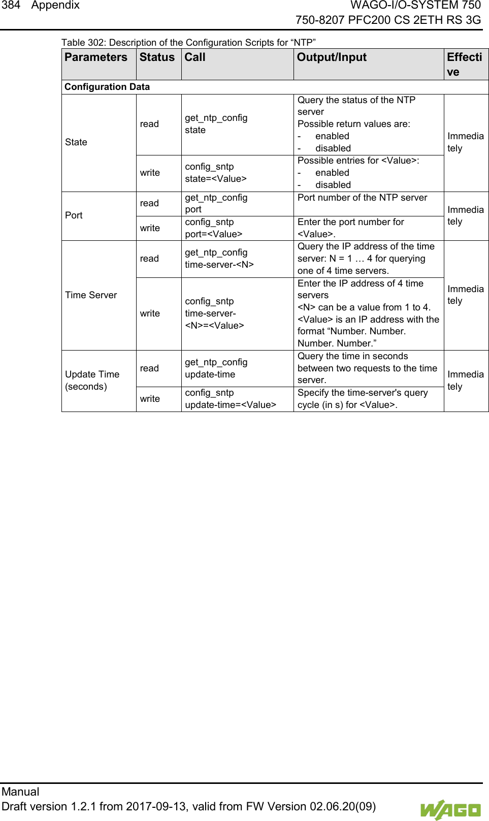
![WAGO-I/O-SYSTEM 750 Commissioning 141 750-8207 PFC200 CS 2ETH RS 3G Manual Draft version 1.2.1 from 2017-09-13, valid from FW Version 02.06.20(09) </dg_ 7.8.1.25 “Configuration of NTP Client” Page The settings for the NTP service are shown on the “Configuration of NTP Client” page. 7.8.1.25.1 “NTP Client Configuration” Group Table 83: WBM “Configuration of NTP Client” Page – “NTP Client Configuration” Group Parameters Explanation Service enabled Enable/disabled time update. Service Result This displays whether time data was accessible and updated via NTP. This field is only displayed with the NTP service enabled. Time server not available until now The time data was not yet updated. Time server available The time data was updated. Time Server n Enter here the IP addresses of up to 4 time servers. Time server No. 1 is requested first of all. If no data is accessible via this server, time server No. 2 is requested etc. Update interval (sec) Specify here the update interval of the time server. Additionally used (assigned by DHCP) The NTP servers assigned if necessary by DHCP (or BootP) are displayed. If no NTP server has been assigned by DHCP (or BootP), “none” is displayed. Click the [Submit] button to apply the changes. The changes are effective immediately. 7.8.1.25.2 “NTP Single Request” Group To update the time immediately, irrespective of the update interval, click [Update Time Now].](https://usermanual.wiki/WAGO-Kontakttechnik-and-KG/PFC200/User-Guide-3565964-Page-141.png)
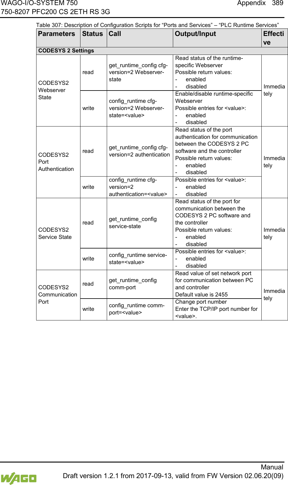
![142 Commissioning WAGO-I/O-SYSTEM 750 750-8207 PFC200 CS 2ETH RS 3G Manual Draft version 1.2.1 from 2017-09-13, valid from FW Version 02.06.20(09) 7.8.1.26 “Configuration of PLC Runtime Services” Page The settings for various services of the activated runtime system are shown on the “Configuration of PLC Runtime Services” page. 7.8.1.26.1 “General Configuration” Group Table 84: WBM “Configuration of PLC Runtime Services” Page – “General Configuration” Group Parameter Explanation Port Authentication Password Specify the new password for port authentication. Confirm Password Enter the new password again for confirmation. Click [Submit] to apply change. The change is effective immediately. 7.8.1.26.2 “CODESYS 2” Group Table 85: WBM “Configuration of CODESYS Services” Page – “CODESYS 2 Web Server” Group Parameter Explanation CODESYS 2 State This displays the status (enabled/disabled) of the CODESYS 2 runtime system. Web server enabled Enable or disable the CODESYS 2 web server for the CODESYS web visualization here. Communication enabled Enable or disable the communication between the CODESYS 2 runtime system and the CODESYS 2 programming system. Communication Port Number Enter here the port number for communication with the CODESYS 2 programming system. Default value is 2455. Port authentication enabled Define here whether port authentication is enabled. If this is enabled, the password specified under “General Configuration” must be entered when logging in via CODESYS 2 IDE. Click [Submit] to apply change. The change is effective immediately. 7.8.1.26.3 “e!RUNTIME” Group Table 86: WBM “Configuration of CODESYS Services” Page – “e!RUNTIME Web Server” Group Parameter Explanation e!RUNTIME State This displays the status of the e!RUNTIME system (enabled/disabled). Web server enabled Enable or disable the e!WEBSERVER for the e!RUNTIME web visualization here. Port authentication enabled Enter here whether a login is required for connecting to the device. The user name is admin and the password specified at “General Configuration.” Click [Submit] to apply change. The change is effective immediately.](https://usermanual.wiki/WAGO-Kontakttechnik-and-KG/PFC200/User-Guide-3565964-Page-142.png)

![144 Commissioning WAGO-I/O-SYSTEM 750 750-8207 PFC200 CS 2ETH RS 3G Manual Draft version 1.2.1 from 2017-09-13, valid from FW Version 02.06.20(09) 7.8.1.27 “SSH Server Settings” Page The settings for the SSH service are shown on the “SSH Server Settings” page. 7.8.1.27.1 “SSH Server” Group Table 87: WBM “SSH Server Settings” Page – “SSH Server” Group Parameter Explanation Service active You can enable/disable the SSH server here. Port Number Specify the port number here. Allow root login You can enable or inhibit root access. Allow password login Activate or deactivate the password query function here. Click on [Submit] to accept the changes. The changes will be effective immediately.](https://usermanual.wiki/WAGO-Kontakttechnik-and-KG/PFC200/User-Guide-3565964-Page-144.png)
![WAGO-I/O-SYSTEM 750 Commissioning 145 750-8207 PFC200 CS 2ETH RS 3G Manual Draft version 1.2.1 from 2017-09-13, valid from FW Version 02.06.20(09) </dg_ 7.8.1.28 “TFTP Server” Page The settings for the TFTP service are shown on the “TFTP Server” page. 7.8.1.28.1 “TFTP Server” Group Table 88: WBM “TFTP Server” Page – “TFTP Server” Group Parameter Explanation Service active Activate or deactivate the TFTP server. Download directory Specify here the path for downloading the server directory. Click on [Submit] to accept the changes. The changes will be effective immediately.](https://usermanual.wiki/WAGO-Kontakttechnik-and-KG/PFC200/User-Guide-3565964-Page-145.png)
![146 Commissioning WAGO-I/O-SYSTEM 750 750-8207 PFC200 CS 2ETH RS 3G Manual Draft version 1.2.1 from 2017-09-13, valid from FW Version 02.06.20(09) 7.8.1.29 “DHCP Configuration” Page The settings for the DHCP service are shown on the “DHCP Configuration” page. 7.8.1.29.1 “DHCP Configuration Xn” Group Table 89: WBM “DHCP Configuration” – “DHCP Configuration Xn” Group Parameter Explanation Service active Enable or disable the DHCP service for the interface Xn. IP Range Enter here a range of available IP addresses. Lease time (sec) Specify the lease time here in seconds. 120 seconds are entered by default. Static hosts/ Static host n This displays the static assignments of MAC IDs to IP addresses. If no assignment was defined, “No static hosts configured” is displayed. New static host Enter here a new static assignment, e.g., “01:02:03:04:05:06=192.168.1.20” or “hostname=192.168.1.20.” You can enter 10 assignments. Click on [Submit] to accept the changes. The changes will be effective immediately. Click on [Add] to accept a new assignment. The change is effective immediately. Click on [Delete] to delete an existing assignment. The change is effective immediately.](https://usermanual.wiki/WAGO-Kontakttechnik-and-KG/PFC200/User-Guide-3565964-Page-146.png)
![WAGO-I/O-SYSTEM 750 Commissioning 147 750-8207 PFC200 CS 2ETH RS 3G Manual Draft version 1.2.1 from 2017-09-13, valid from FW Version 02.06.20(09) 7.8.1.30 “Configuration of DNS Service” Page The settings for the DNS service are shown on the “Configuration of DNS Service” page. 7.8.1.30.1 “DNS Service” Group Table 90: WBM “Configuration of DNS Service” Page – “DNS Service” Group Parameter Explanation Service active You can enable/disable the DNS server service here. Mode Select here the operating mode of the DNS server: Proxy Requests are buffered to optimize throughput. Relay All requests are routed directly. Static hosts This displays the static assignments of IP addresses to names. If no assignment was defined, “No static hosts configured” is displayed. New static host Enter here a new static assignment, e.g., “192.168.1.20:hostname.” You can enter 10 assignments. Click on [Submit] to accept the changes. The changes will be effective immediately. Click on [Add] to accept a new assignment. The change is effective immediately. Click on [Delete] to delete an existing assignment. The change is effective immediately.](https://usermanual.wiki/WAGO-Kontakttechnik-and-KG/PFC200/User-Guide-3565964-Page-147.png)
![148 Commissioning WAGO-I/O-SYSTEM 750 750-8207 PFC200 CS 2ETH RS 3G Manual Draft version 1.2.1 from 2017-09-13, valid from FW Version 02.06.20(09) 7.8.1.31 “MODBUS Services Configuration” Page The settings for various MODBUS services are shown on the “MODBUS Services Configuration” page. The groups are only visible if the e!RUNTIME system is enabled. Otherwise an information text is displayed. 7.8.1.31.1 “MODBUS TCP” Group Table 91: WBM “MODBUS Services Configuration” Page – “MODBUS TCP” Group Parameter Explanation Service active Disable or enable the MODBUS/TCP service here. Click the [Submit] button to apply the changes. The change is effective immediately. 7.8.1.31.2 “MODBUS UDP” Group Table 92: WBM “MODBUS Configuration Services” Page – “MODBUS UDP” Group Parameter Explanation Service active Disable/enable the MODBUS-UDP service here. Click the [Submit] button to apply the changes. The change is effective immediately.](https://usermanual.wiki/WAGO-Kontakttechnik-and-KG/PFC200/User-Guide-3565964-Page-148.png)
![WAGO-I/O-SYSTEM 750 Commissioning 149 750-8207 PFC200 CS 2ETH RS 3G Manual Draft version 1.2.1 from 2017-09-13, valid from FW Version 02.06.20(09) 7.8.1.32 “Configuration of General SNMP Parameters” Page The general settings for SNMP are given on the “Configuration of General SNMP Parameters” page. 7.8.1.32.1 “General SNMP Configuration” Group Table 93: WBM “Configuration of General SNMP Parameters” Page – “General SNMP Configuration” Group Parameter Explanation Service active Activate/deactivate the SNMP service. Name of device Enter here the device name (sysName). Description Enter here the device description (sysDescription). Physical location Enter here the location of the device (sysLocation). Contact Enter here the email contact address (sysContact). Click the [Submit] button to apply the changes. The changes only take effect after restarting the controller. For this purpose, use the WBM reboot function. Do not shut down the controller too early!](https://usermanual.wiki/WAGO-Kontakttechnik-and-KG/PFC200/User-Guide-3565964-Page-149.png)
![150 Commissioning WAGO-I/O-SYSTEM 750 750-8207 PFC200 CS 2ETH RS 3G Manual Draft version 1.2.1 from 2017-09-13, valid from FW Version 02.06.20(09) 7.8.1.33 “Configuration of SNMP v1/v2c Parameters” Page The general settings for SNMP v1/v2c are shown on the “Configuration of SNMP v1/v2c Parameters” page. 7.8.1.33.1 “SNMP v1/v2c Manager Configuration” Group Table 94: WBM “Configuration of SNMP v1/v2c Parameters” Page – “SNMP v1/v2c Manager Configuration” Group Parameter Explanation Protocol enabled It is displayed the SNMP protocol for v1/v2c is activated. The local community name is deleted when the protocol is deactivated. Local Community Name Specify here the community name for the SNMP manager configuration. The community name can establish relationships between SNMP managers and agents who are respectively referred to as “Community” and who control identification and access between SNMP participants. The community name can be up to 32 characters long and must not include spaces. To use the SNMP protocol, a valid community name must always be specified. The default community name is “public.” Click [Change] to apply changes. The changes only take effect after restarting the controller. For this purpose, use the WBM reboot function. Do not shut down the controller too early! 7.8.1.33.2 “Actually Configured Trap Receivers” Group(s) Table 95: WBM “Configuration of SNMP v1/v2c Parameters” Page – “Actually Configured Trap Receivers” Group Parameter Explanation Count This displays number of configured trap receivers.](https://usermanual.wiki/WAGO-Kontakttechnik-and-KG/PFC200/User-Guide-3565964-Page-150.png)
![WAGO-I/O-SYSTEM 750 Commissioning 151 750-8207 PFC200 CS 2ETH RS 3G Manual Draft version 1.2.1 from 2017-09-13, valid from FW Version 02.06.20(09) 7.8.1.33.3 “Trap Receiver n” Group(s) A dedicated group with the following information is displayed for each trap receiver: Table 96: WBM “Configuration of SNMP v1/v2c Parameters” Page – “Trap Receiver n” Group(s) Parameter Explanation IP Address The IP address for the trap receiver (management station) is displayed here. Community Name This displays the community name for the trap receiver configuration. The community name can be evaluated by the trap receiver. Version This displays the SNMP version, via which the traps are sent: v1 or v2c (traps higher than v3 are displayed in a separate form). Click [Delete] to delete the trap receiver. The changes only take effect after restarting the controller. For this purpose, use the WBM reboot function. Do not shut down the controller too early! 7.8.1.33.4 “Add New Trap Receiver” Group You can enter 10 trap receivers. Table 97: WBM “Configuration of SNMP v1/v2c Parameters” Page – “Add New Trap Receiver” Group Parameter Explanation IP Address Specify the IP address for the new trap receiver (management station) here. Community Name Specify here the community name for the new trap receiver configuration. The community name can be evaluated by the trap receiver. The community name can be up to 32 characters long and must not include spaces. Version Specify the SNMP version that will send the traps: v1 or v2c (traps higher than v3 are configured in a separate form). Click [Add] to add a new trap receiver. The changes only take effect after restarting the controller. For this purpose, use the WBM reboot function. Do not shut down the controller too early!](https://usermanual.wiki/WAGO-Kontakttechnik-and-KG/PFC200/User-Guide-3565964-Page-151.png)
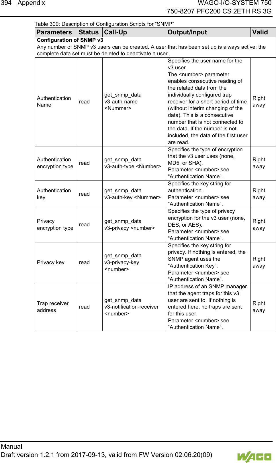
![152 Commissioning WAGO-I/O-SYSTEM 750 750-8207 PFC200 CS 2ETH RS 3G Manual Draft version 1.2.1 from 2017-09-13, valid from FW Version 02.06.20(09) </dg_ 7.8.1.34 “Configuration of SNMP v3 Users” Page The general settings for SNMP v3 are shown on the “Configuration of SNMP v3 Users” page. 7.8.1.34.1 “Actually Configured v3 Users” Group(s) Table 98: WBM “Configuration of SNMP v3” Page – “Actually Configured v3 Users” Group Parameters Explanation Count The number of configured v3 users is displayed. 7.8.1.34.2 “v3 User n” Group(s) A group with the following information is displayed for each user: Table 99: WBM “Configuration of SNMP v3 Users” Page – “v3 User n” Group(s) Parameters Explanation Security Authentication Name The user name is displayed. Authentication Type The authentication type for the SNMP v3 packets is displayed here. Possible values: - Use no authentication (“None”) - Message Digest 5 (“MD5”) - Secure Hash Algorithm (“SHA”) Authentication Key (min. eight char.) The authentication key is displayed. Privacy The encryption algorithm for the SNMP message is displayed here. Possible values: - No encryption (“None”) - Data Encryption Standard (“DES”) - Advanced Encryption Standard (“AES”) Privacy Key (min. eight char.) The key for encryption of the SNMP message is displayed here. If nothing is displayed here, the “authentication key” is automatically used. Notification Receiver IP The IP address of a trap receiver for v3 traps is displayed here. If no v3 traps are to be sent for this user, this field remains blank. Click [Delete] to delete the user. The changes only take effect after restarting the controller. For this purpose, use the WBM reboot function. Do not shut down the controller too early!](https://usermanual.wiki/WAGO-Kontakttechnik-and-KG/PFC200/User-Guide-3565964-Page-152.png)
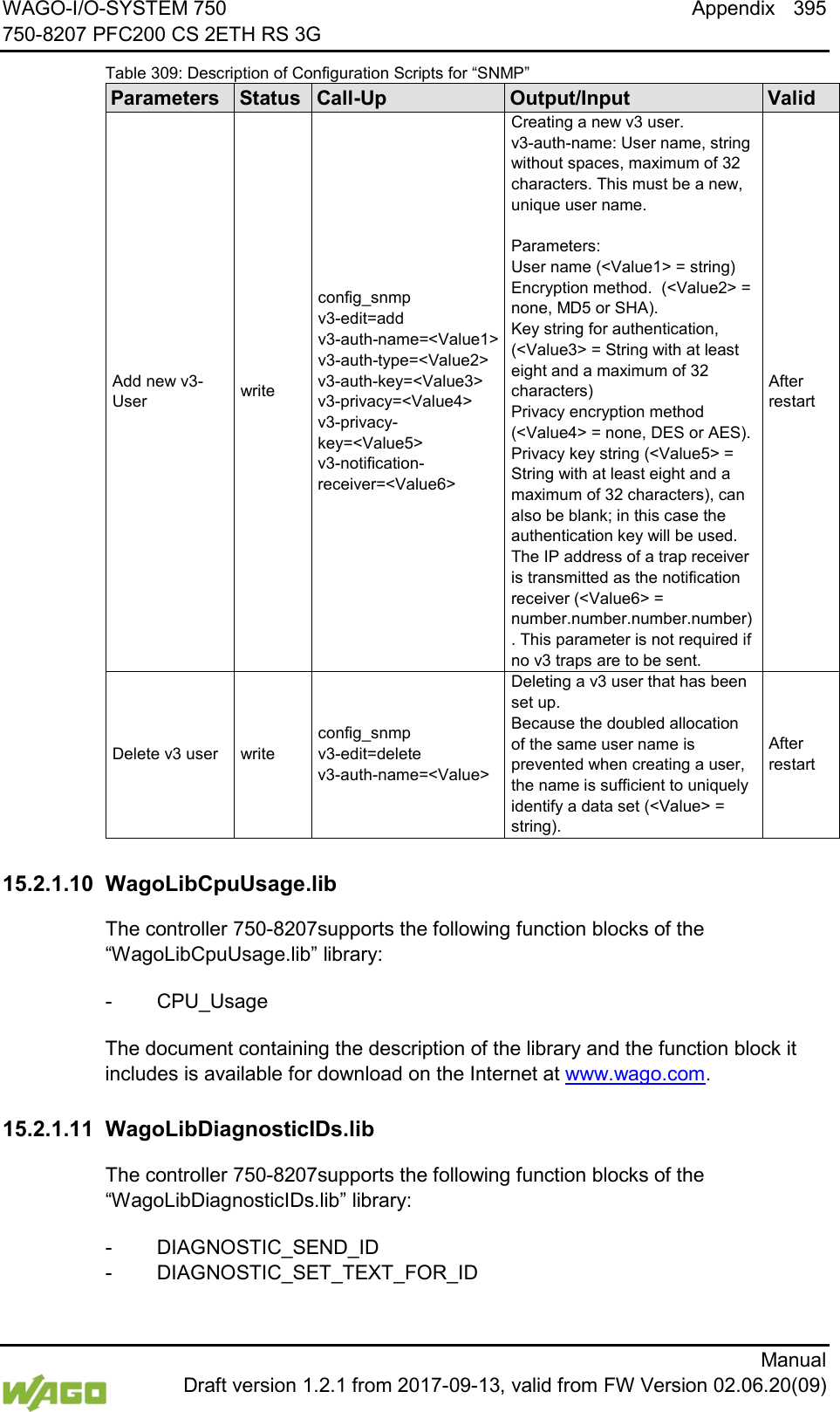
![WAGO-I/O-SYSTEM 750 Commissioning 153 750-8207 PFC200 CS 2ETH RS 3G Manual Draft version 1.2.1 from 2017-09-13, valid from FW Version 02.06.20(09) 7.8.1.34.3 “Add New v3 User” Group You can enter 10 users. Table 100: WBM “Configuration of SNMP v3 Users” Page – “Add New v3 User” Group Parameters Explanation Security Authentication Name Enter the user name here. This name must be unique; a pre-existing user name is not accepted when entered here. The security authentication name can have a maximum 32 characters, without any spaces. Authentication Type Specify the authentication type for the SNMP v3 packets. Possible values: - Use no authentication (“None”) - Message Digest 5 (“MD5”) - Secure Hash Algorithm (“SHA”) Authentication Key (min. eight char.) Specify the authentication key here. This authentication key must have between eight and 32 characters, without any spaces. Privacy Specify the encryption algorithm for the SNMP message here. Possible values: - No encryption (“None”) - Data Encryption Standard (“DES”) - Advanced Encryption Standard (“AES”) Privacy Key (min. eight char.) Enter the key for encryption of the SNMP message here. If nothing is specified here, the “authentication key” is automatically used. The privacy key must have between eight and 32 characters, without any spaces. Notification Receiver IP Specify an IP address for a trap receiver for v3 traps here. If no v3 traps are to be sent for this user, this field remains blank. Click [Add] to add a new user. The changes only take effect after restarting the controller. For this purpose, use the WBM reboot function. Do not shut down the controller too early!](https://usermanual.wiki/WAGO-Kontakttechnik-and-KG/PFC200/User-Guide-3565964-Page-153.png)
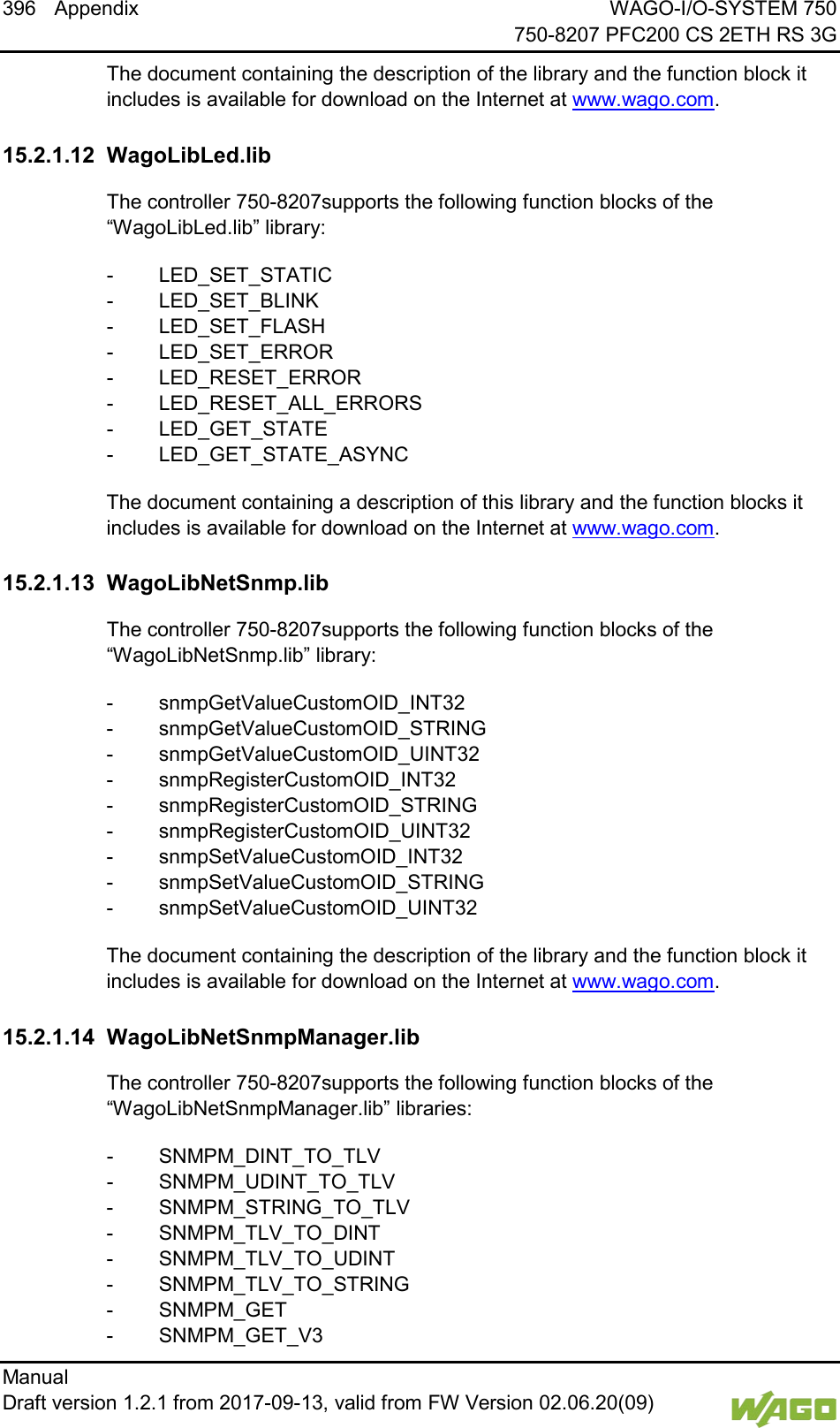
![154 Commissioning WAGO-I/O-SYSTEM 750 750-8207 PFC200 CS 2ETH RS 3G Manual Draft version 1.2.1 from 2017-09-13, valid from FW Version 02.06.20(09) </dg_ 7.8.1.35 “Diagnostic Information” Page The settings for displaying diagnostic messages are shown on the “Diagnostic Information” page. Table 101: WBM “Diagnostic Information” Page Parameter Explanation Read all notifications Activate display of all messages. Read only the last n Activate display of only the last n messages. You also specify the number of messages to be displayed. Automatic refresh cycle (sec) Select the check box to enable cyclic refresh. Enter the cycle time in seconds in which a cyclic refresh is performed. The label of the button (“Refresh”/“Start“/“Stop”) changes depending on status. To refresh the display or to enable cyclic refresh, click the [Refresh] button. This button is only visible if the cyclic refresh is not enabled or stopped. To enable cyclic refresh, click the [Start] button. The button is only visible if cyclic refresh is enabled and has not yet started. To stop cyclic refresh again, click the [Stop] button. The button is only visible if cyclic refresh is enabled. The cyclical update is performed for as long as the “Diagnostic” page is opened. If you change the WBM page, the update is stopped until you call up the “Diagnostic” Page again. The messages are displayed below the settings.](https://usermanual.wiki/WAGO-Kontakttechnik-and-KG/PFC200/User-Guide-3565964-Page-154.png)
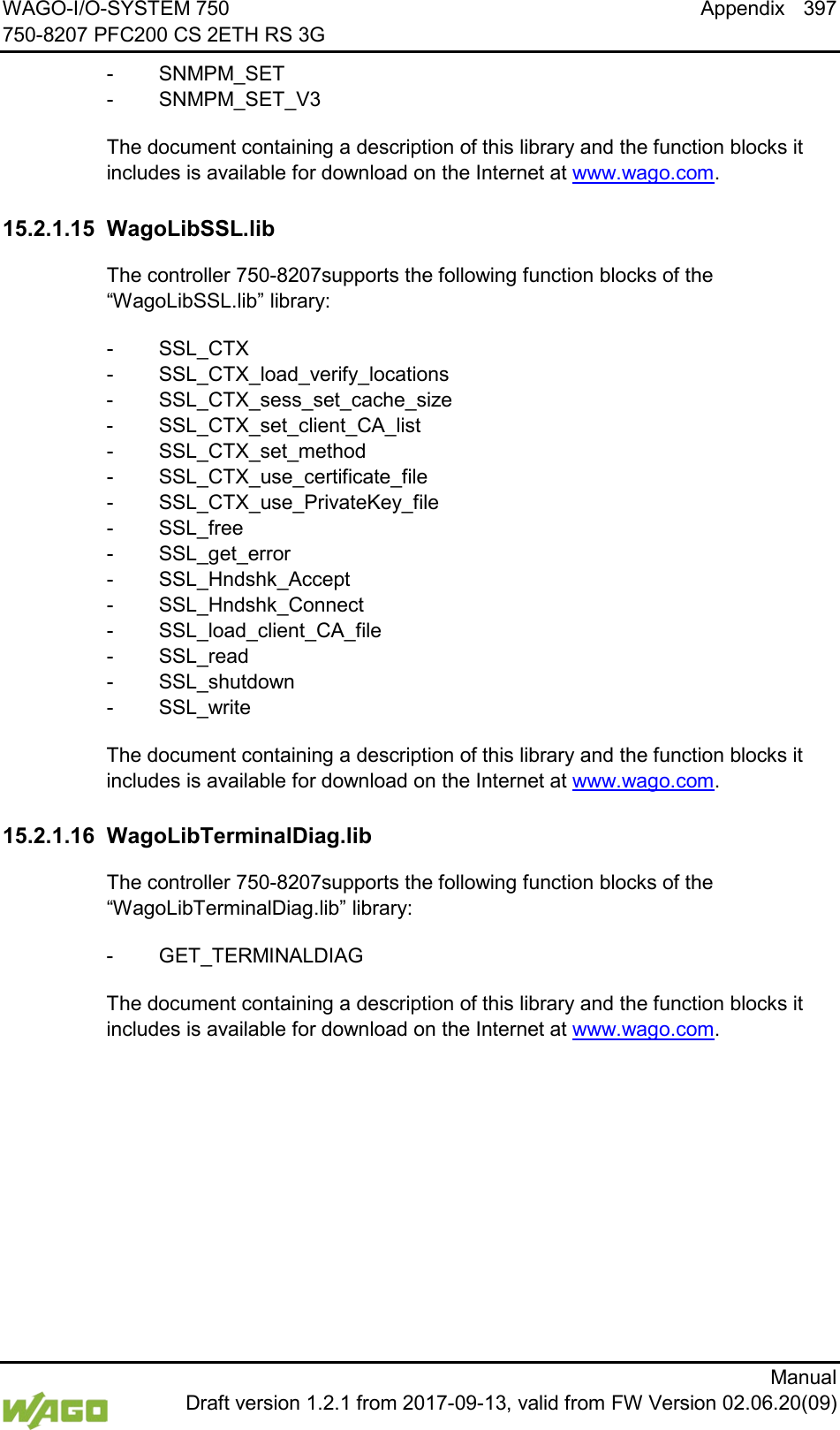
![WAGO-I/O-SYSTEM 750 Commissioning 155 750-8207 PFC200 CS 2ETH RS 3G Manual Draft version 1.2.1 from 2017-09-13, valid from FW Version 02.06.20(09) 7.8.1.36 “Configuration of internal 3G Modem” Page The modem settings are available on the “Configuration of internal 3G Modem” page. 7.8.1.36.1 “SIM Authentication” Group Table 102: WBM “Configuration of internal 3G Modem” Page – “SIM Authentication” Group Parameters Explanation State The status of the SIM authentication is displayed. Ready Authentication was successful. PIN requested The PIN must be entered. The number of remaining attempts is displayed. PUK requested The PIN was not entered correctly, the PUK must be specified along with a new PIN. PIN Enter the PIN. The field is only displayed if PIN entry is required. PUK Enter the PUK. The field is only displayed if PUK try is required. To apply the entries, click the [Submit] button. The changes will be effective immediately.](https://usermanual.wiki/WAGO-Kontakttechnik-and-KG/PFC200/User-Guide-3565964-Page-155.png)
![156 Commissioning WAGO-I/O-SYSTEM 750 750-8207 PFC200 CS 2ETH RS 3G Manual Draft version 1.2.1 from 2017-09-13, valid from FW Version 02.06.20(09) 7.8.1.36.2 “Mobile Network Configuration” Group Table 103: WBM “Configuration of internal 3G Modem” Page – “Mobile Network Configuration” Group Parameters Explanation State The network status is displayed. Signal Quality (%) The current signal quality is displayed. Operator The provider and network type currently in use are displayed. Selection Mode Select the mode for selecting the provider used: Automatic The network is selected by the modem itself based on the SIM card settings. Automatic – UMTS preferred Like “Automatic”, but the UMTS network is preferred. Automatic – GSM preferred Like “Automatic”, but the GSM network is preferred. Automatic – UMTS only Like “Automatic”, but restricted to the UMTS network.* Automatic – GSM only Like “Automatic”, but restricted to the GSM network.* Manual Manual network selection from the Provider selection list; if you set the “Manual” mode, the provider list is then refreshed. This may take some time (see section “‘Provider List’ Group”). Provider Select the provider. The field is only visible if Selection Mode is set to “Manual”. The selection list contains all providers from the provider list that are actually available. The selection list is only available if the provider list has been refreshed. * However, the restriction applies only when more than one possible network is available, e.g., if “Automatic UMTS only” is selected, but only a GSM network is available from the provider, then the modem still logs into the GSM network. Click on [Submit] to accept the changes. The changes will be effective immediately.](https://usermanual.wiki/WAGO-Kontakttechnik-and-KG/PFC200/User-Guide-3565964-Page-156.png)
![WAGO-I/O-SYSTEM 750 Commissioning 157 750-8207 PFC200 CS 2ETH RS 3G Manual Draft version 1.2.1 from 2017-09-13, valid from FW Version 02.06.20(09) 7.8.1.36.3 “Provider List” Group Table 104: WBM “Configuration of internal 3G Modem” Page – “Provider List” Group Parameters Explanation <Provider> | <Network> <ID>, <Status> All available providers with the respective network, its ID and the current status are displayed. Refreshing the provider list may take some time (approx. 1 minute), during which the WBM waits for the modem response. The process is canceled after 2 minutes or immediately if the modem executes another, non-interruptible action. The list is therefore refreshed only on request, either by clicking the [Refresh] button or setting the Selection Mode to “Manual”. The selection list for the provider (“Mobile Network Configuration” Group) can only be filled in when the provider list has been refreshed. In normal operation, the provider list changes only rarely, i.e., continuous refreshing is not required. Click [Refresh] to refresh the list. 7.8.1.36.4 “Network Package Service” Group Table 105: WBM “Configuration of internal 3G Modem” Page – “Network Package Service” Group Parameters Explanation State The registry state of the “Network Package Service” is displayed. APN Enter the APN access point (Access Point Name) of the SIM card provider. User Enter the user name for the access point of the SIM card provider. Password Enter the password for the access point of the SIM card provider. Authentication Type Select the authentication type: None No authentication PAP Password Authentication Protocol CHAP Challenge Handshake Authentication Protocol PAP or CHAP When possible, the secure CHAP is used, otherwise PAP. Click on [Submit] to accept the changes. The changes will be effective immediately.](https://usermanual.wiki/WAGO-Kontakttechnik-and-KG/PFC200/User-Guide-3565964-Page-157.png)
![158 Commissioning WAGO-I/O-SYSTEM 750 750-8207 PFC200 CS 2ETH RS 3G Manual Draft version 1.2.1 from 2017-09-13, valid from FW Version 02.06.20(09) 7.8.1.36.5 “Upload and activate new Modem Software” Group Table 106: WBM “Configuration of internal 3G Modem” Page – “Upload and activate new Modem Software” Group Parameters Explanation Currently used The current modem firmware version is displayed. New Software Enter the firmware version to be installed. To select a firmware file in Explorer, click the [Browse] button. To install and enable the firmware, click the [Start Upload] button. The changes will be effective immediately.](https://usermanual.wiki/WAGO-Kontakttechnik-and-KG/PFC200/User-Guide-3565964-Page-158.png)
![WAGO-I/O-SYSTEM 750 Commissioning 159 750-8207 PFC200 CS 2ETH RS 3G Manual Draft version 1.2.1 from 2017-09-13, valid from FW Version 02.06.20(09) 7.8.1.37 “Configuration of OpenVPN and IPsec” Page The general settings for SNMP v1/v2c are shown on the “Configuration of SNMP v1/v2c Parameters” page. 7.8.1.37.1 “OpenVPN” Group Table 107: WBM “Configuration of OpenVPN and IPsec” Page – “OpenVPN” Group Parameters Explanation Current State The current status of the OpenVPN service is displayed. stopped The service is disabled. running The service is enabled. OpenVPN enabled Enable or disable the OpenVPN service. openvpn.config Select an OpenVPN configuration file to be transferred from PC to controller or vice versa. To apply a status change, click the [Submit] button. To select a file on the controller or PC, click the [Browse] button. To transfer the selected file from the PC to the controller, click [Start Upload] button. To transfer the selected file from the controller to the PC, click [Start Download] button. The changes only take effect after restarting the controller. For this purpose, use the WBM reboot function. Do not shut down the controller too early! 7.8.1.37.2 “IPsec” Group Table 108: WBM “Configuration of OpenVPN and IPsec” Page – “IPsec” Group Parameters Explanation Current State The current status of the IPsec service is displayed. stopped The service is disabled. running The service is enabled. IPsec enabled Enable or disable the IPsec service. ipsec.config Select an IPsec configuration file to be transferred from PC to controller or vice versa. ipsec.secrets Select an IPsec configuration file to be transferred from PC to controller. To apply a status change, click the [Submit] button. To select a file on the controller or PC, click the [Browse] button. To transfer the selected file to the controller, click [Start Upload] button.](https://usermanual.wiki/WAGO-Kontakttechnik-and-KG/PFC200/User-Guide-3565964-Page-159.png)
![160 Commissioning WAGO-I/O-SYSTEM 750 750-8207 PFC200 CS 2ETH RS 3G Manual Draft version 1.2.1 from 2017-09-13, valid from FW Version 02.06.20(09) To transfer the selected file from the controller to the PC, click [Start Download] button. The changes only take effect after restarting the controller. For this purpose, use the WBM reboot function. Do not shut down the controller too early! 7.8.1.37.3 “Certificate Upload” Group Table 109: WBM “Configuration of OpenVPN and IPsec” Page – “Certificate Upload” Group Parameters Explanation New Certificate Select an certificate for transfer from a PC to the controller. New Private Key Select a key for transfer from a PC to the controller. To select a file on the PC, click the [Browse] button. To transfer the selected file to the controller, click [Start Upload] button. The changes will be effective immediately. The certificates are saved in the directory “/etc/certificates/” and the keys in the directory “/etc/certificates/keys/”. 7.8.1.37.4 “Certificate List” Group Table 110: WBM “Configuration of OpenVPN and IPsec” Page – “Certificate List” Group Parameters Explanation <certificate name> The loaded certificates are displayed. If no certificate has been loaded. “No certificates existing” is displayed. Click [Delete] to delete an entry. The changes will be effective immediately. 7.8.1.37.5 “Private Key List” Group Table 111: WBM “Configuration of OpenVPN and IPsec” Page – “Private Key List” Group Parameters Explanation <key name> The loaded keys are displayed. If no keys has been loaded. “No keys existing” is displayed. Click [Delete] to delete an entry. The changes will be effective immediately.](https://usermanual.wiki/WAGO-Kontakttechnik-and-KG/PFC200/User-Guide-3565964-Page-160.png)
![WAGO-I/O-SYSTEM 750 Commissioning 161 750-8207 PFC200 CS 2ETH RS 3G Manual Draft version 1.2.1 from 2017-09-13, valid from FW Version 02.06.20(09) 7.8.1.38 “Security Settings” Page The network security settings are found on the “Security Settings” page. 7.8.1.38.1 “TLS Configuration” Group Table 112: “Security Settings” WBM Page – “TLS Configuration” Group Parameters Explanation TLS configuration Here you can set what TLS versions and cryptographic methods are allowed for HTTPS. Standard The Webserver allows TLS 1.0, TLS 1.1 and TLS 1.2, as well as cryptographic methods that are no longer considered secure. Strong The Webserver only allows TLS Version 1.2 and strong algorithms. Older software and older operating systems may not support TLS 1.2. Click on [Submit] to accept the changes. The changes will be effective immediately. BSI Technical Guidelines TR-02102 The rules for the “Strong” setting are based on technical guidelines TR-02102 of the German Federal Office for Information Security. You can find the guidelines on the Internet at: https://www.bsi.bund.de > “Publications” > “Technical Guidelines.”](https://usermanual.wiki/WAGO-Kontakttechnik-and-KG/PFC200/User-Guide-3565964-Page-161.png)
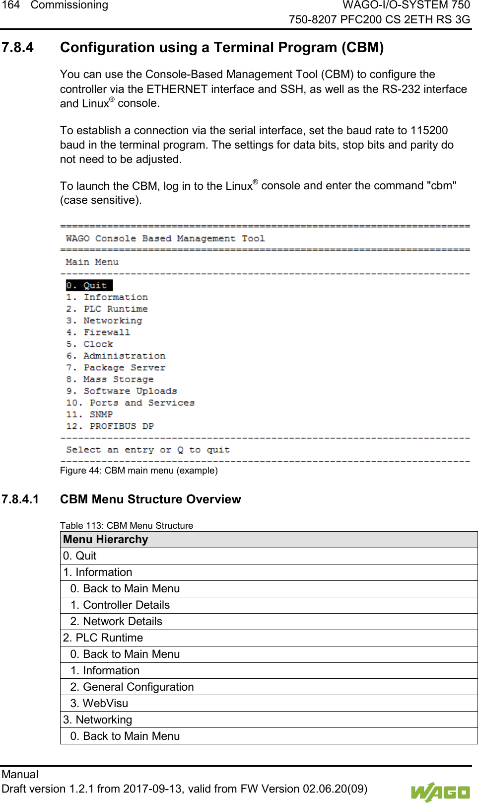
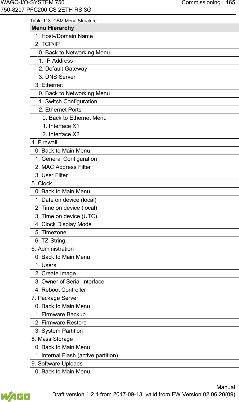
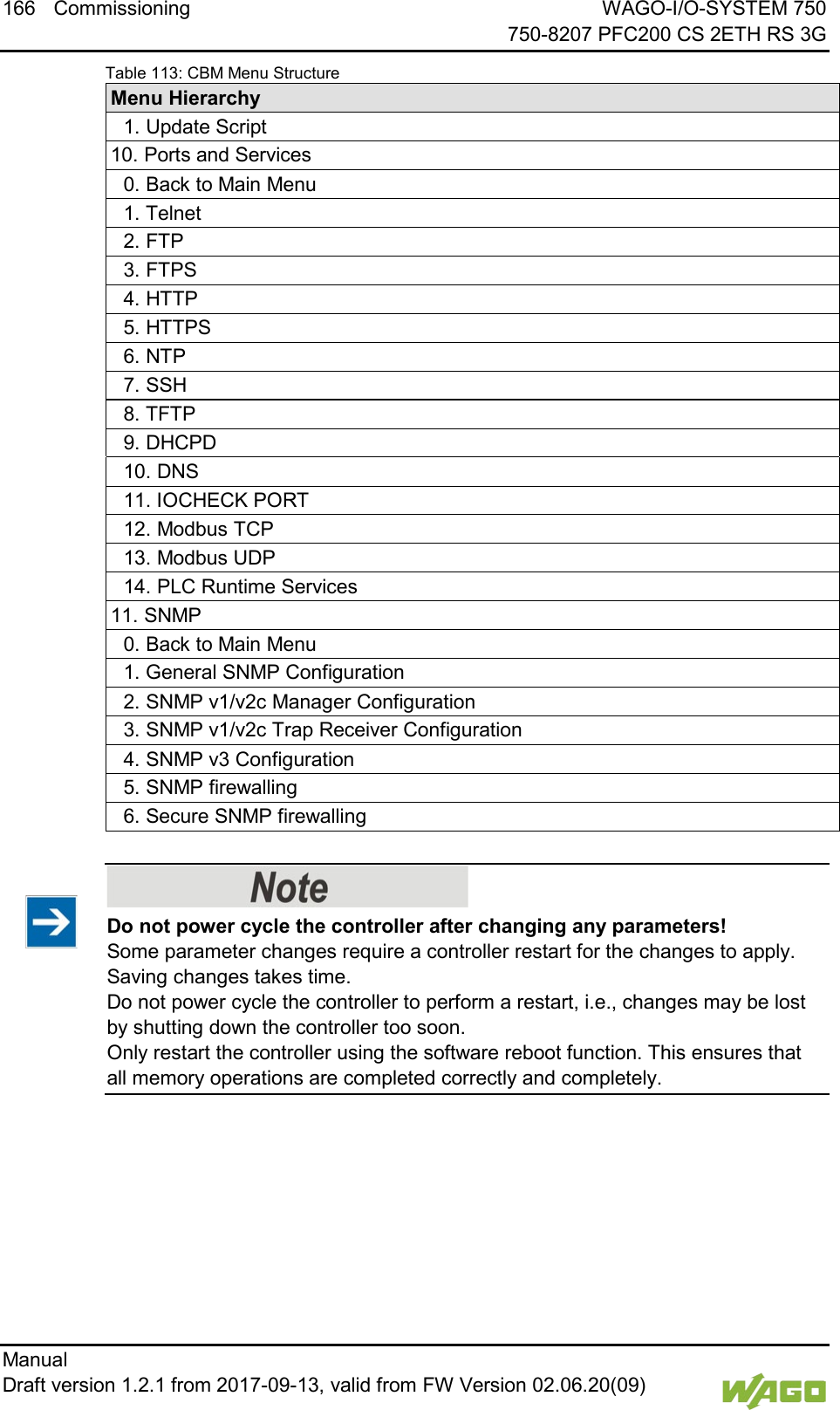
![WAGO-I/O-SYSTEM 750 Commissioning 167 750-8207 PFC200 CS 2ETH RS 3G Manual Draft version 1.2.1 from 2017-09-13, valid from FW Version 02.06.20(09) 7.8.4.2 “Information” Menu This menu contains other submenus with information on the controller and network. Table 114: “Information” Menu Menu Item Explanation 0. Back to … Back to the higher-level menu 1. Controller Details Opens a submenu with controller properties 2. Network Details Opens a submenu with controller network and interface properties To make a selection, choose the appropriate menu item. To return to the higher-level menu, press [Q]. 7.8.4.2.1 “Information” > “Controller Details” Submenu In this submenu, the controller properties are displayed. Table 115: “Information” > “Controller Details” Submenu Parameters Explanation Product Description Controller identification Order Number Item number of the controller License Information Notification that the CODESYS runtime system is available Firmware Revision Firmware status To return to the higher-level menu, press [Q] or [Return].](https://usermanual.wiki/WAGO-Kontakttechnik-and-KG/PFC200/User-Guide-3565964-Page-167.png)
![168 Commissioning WAGO-I/O-SYSTEM 750 750-8207 PFC200 CS 2ETH RS 3G Manual Draft version 1.2.1 from 2017-09-13, valid from FW Version 02.06.20(09) 7.8.4.2.2 “Information” > “Network Details” Submenu In this submenu, the network and interface properties of the controller are displayed. If the EHERNET interfaces are operated in “Switched” mode, a common table (“X1/X2”) is displayed for both connections. If the EHERNET interfaces are operated in “Separated” mode, an individual table (“X1” / “X2”) is displayed for each connection. Table 116: “Information” > “Network Details” Submenu Parameters Explanation State Status of the ETHERNET interface (enabled/disabled) Mac Address MAC address identifies and addresses the controller IP Address Current IP address of the controller and (in brackets) the reference type (static/bootp/dhcp) Subnet Mask Current subnet mask of the controller To return to the higher-level menu, press [Q] or [Return].](https://usermanual.wiki/WAGO-Kontakttechnik-and-KG/PFC200/User-Guide-3565964-Page-168.png)
![WAGO-I/O-SYSTEM 750 Commissioning 169 750-8207 PFC200 CS 2ETH RS 3G Manual Draft version 1.2.1 from 2017-09-13, valid from FW Version 02.06.20(09) 7.8.4.3 “PLC Runtime” Menu This menu contains other submenus with information and settings for the runtime system. Table 117: “PLC Runtime” Menu Menu Item Explanation 0. Back to … Back to the higher-level menu 1. Information Opens a submenu with information on the runtime system 2. General Configuration Opens a submenu with settings for the runtime system 3. WebVisu Opens a submenu with settings for the Web visualization To make a selection, choose the appropriate menu item. To return to the higher-level menu, press [Q]. 7.8.4.3.1 “PLC Runtime” > “Information” Submenu This submenu contains other submenus with information on the runtime system and PLC program. Menu items 2 … 6 only appear if CODESYS 2 is set as the runtime system. Table 118: “PLC Runtime” > “Information” Submenu Menu Item Explanation 0. Back to … Back to the higher-level menu 1. Runtime Version Opens a submenu to display the runtime version 2. Webserver Version Opens a submenu to display the Webserver version 3. State Opens a submenu to display the PLC operating state 4. Number of Tasks Opens a submenu to display the number of tasks in the PLC program 5. Project Details Opens a submenu to display the PLC program project information 6. Tasks Opens a submenu to display the tasks in the PLC program To make a selection, choose the appropriate menu item. To return to the higher-level menu, press [Q].](https://usermanual.wiki/WAGO-Kontakttechnik-and-KG/PFC200/User-Guide-3565964-Page-169.png)
![170 Commissioning WAGO-I/O-SYSTEM 750 750-8207 PFC200 CS 2ETH RS 3G Manual Draft version 1.2.1 from 2017-09-13, valid from FW Version 02.06.20(09) 7.8.4.3.2 “Information” > “Runtime Version” Submenu In this submenu, the runtime version is displayed. Table 119: “PLC Runtime” > “Information” > “Runtime Version” Submenu Parameters Explanation Version The version of the currently enabled runtime system is shown. If the runtime system is disabled, “None” is displayed. To return to the higher-level menu, press [Q] or [Return]. 7.8.4.3.3 “Information” > “Webserver Version” Submenu In this submenu, the Webserver version is displayed. The submenu only appears when CODESYS 2 is enabled as the runtime system. Table 120: “PLC Runtime” > “Information” > “Webserver Version” Submenu Parameters Explanation Version The Webserver version is displayed. To return to the higher-level menu, press [Q] or [Return]. 7.8.4.3.4 “Information” > “State” Submenu In this submenu, the PLC operating state is displayed. The submenu only appears when CODESYS 2 is enabled as the runtime system. Table 121: “PLC Runtime” > “Information” > “State” Submenu Parameters Explanation State The PLC operating state is shown. STOP PLC program is not executed. RUN PLC program is executed. To return to the higher-level menu, press [Q] or [Return].](https://usermanual.wiki/WAGO-Kontakttechnik-and-KG/PFC200/User-Guide-3565964-Page-170.png)
![WAGO-I/O-SYSTEM 750 Commissioning 171 750-8207 PFC200 CS 2ETH RS 3G Manual Draft version 1.2.1 from 2017-09-13, valid from FW Version 02.06.20(09) 7.8.4.3.5 “Information” > “Number of Tasks” Submenu In this submenu, the number of tasks in the PLC program are displayed. The submenu only appears when CODESYS 2 is enabled as the runtime system. Table 122: “PLC Runtime” > “Information” > “Number of Tasks” Submenu Parameters Explanation Number of Tasks The number of tasks in the PLC program is shown. To return to the higher-level menu, press [Q] or [Return]. 7.8.4.3.6 “Information” > “Project Details” Submenu In this submenu, project information from the PLC program is displayed. The submenu only appears when CODESYS 2 is enabled as the runtime system and the program is executed. Table 123: “PLC Runtime” > “Information” > “Project Details” Submenu Parameters Explanation Date Display of project information that the programmer entered in the PLC program (in the programming software under Project > Project Information ...) Descriptive text with up to 1024 characters is displayed under “Description”. Title Version Author Description To return to the higher-level menu, press [Q] or [Return]. 7.8.4.3.7 “Information” > “Tasks” Submenu In this submenu, tasks from the PLC program are displayed. An entry is generated for each task. The submenu only appears when CODESYS 2 is enabled as the runtime system. Table 124: “PLC Runtime” > “Information” > “Tasks” Submenu Menu Item Explanation 0. Back to … Back to the higher-level menu n. Task n Opens a submenu with information on the selected task To make a selection, choose the appropriate menu item. To return to the higher-level menu, press [Q].](https://usermanual.wiki/WAGO-Kontakttechnik-and-KG/PFC200/User-Guide-3565964-Page-171.png)
![172 Commissioning WAGO-I/O-SYSTEM 750 750-8207 PFC200 CS 2ETH RS 3G Manual Draft version 1.2.1 from 2017-09-13, valid from FW Version 02.06.20(09) 7.8.4.3.8 “Tasks” > “Task n” Submenu In this submenu, information on the selected task is displayed. The submenu only appears when CODESYS 2 is enabled as the runtime system. Table 125: “PLC Runtime” > “Information” > “Tasks” > “Task n” Submenu Parameters Explanation Cycle count Number of task cycles since the system start Cycle time (µsec) Currently measured task cycle time for the task Cycle time min (µsec) Minimum task cycle time for the task since the system start Cycle time max (µsec) Maximum task cycle time for the task since the system start Cycle time avg (µsec) Average task cycle time since the system start Status Task status (e.g., RUN, STOP) Mode Task execution mode (e.g., in cycles) Priority Set task priority Interval (msec) Set task interval To return to the higher-level menu, press [Q] or [Return]. 7.8.4.3.9 “PLC Runtime” > “General Configuration” Submenu This submenu contains other submenus with general settings for the runtime system. Table 126: “PLC Runtime” > “General Configuration” Submenu Menu Item Explanation 0. Back to … Back to the higher-level menu 1. PLC Runtime Version Opens a submenu for the CODESYS runtime system settings 2. Home Dir On SD Card Opens a submenu for the home directory settings To make a selection, choose the appropriate menu item. To return to the higher-level menu, press [Q].](https://usermanual.wiki/WAGO-Kontakttechnik-and-KG/PFC200/User-Guide-3565964-Page-172.png)
![WAGO-I/O-SYSTEM 750 Commissioning 173 750-8207 PFC200 CS 2ETH RS 3G Manual Draft version 1.2.1 from 2017-09-13, valid from FW Version 02.06.20(09) 7.8.4.3.10 “General Configuration” > “PLC Runtime Version” Submenu In this submenu, select which PLC runtime system is enabled. Table 127: “PLC Runtime” > “General Configuration” > “PLC Runtime Version” Submenu Menu Item Explanation 0. Back to … Back to the higher-level menu 1. None No runtime system is enabled. 2. CODESYS 2 The CODESYS 2 runtime system is enabled. 3. e!RUNTIME The e!RUNTIME runtime system is enabled. All data is deleted when switching the runtime system! The runtime system’s home directory is completely deleted when switching the runtime system! To make a selection, choose the appropriate menu item. To return to the higher-level menu, press [Q]. 7.8.4.3.11 “General Configuration” > “Home Dir On SD Card” Submenu In this submenu, define if the home directory for the runtime system should be moved to the memory card. Table 128: “PLC Runtime” > “General Configuration” > “Home Dir On SD Card” Submenu Menu Item Explanation 0. Back to … Back to the higher-level menu 1. Enable The home directory is moved to the memory card. 2. Disable The home directory is stored in the internal memory. Insert a memory card before switching the home directory! When moving the home directory to the memory card, insert a memory card formatted to support file system. Only the first partition of a memory card can be accessed at /media/sd and can be used as the home directory. Perform a reset before switching the home directory! Stop IEC-61131 applications in use before switching the home directory of the runtime system. Restore the device to its initial state using the “Reset” function. Any boot project is deleted. To make a selection, choose the appropriate menu item. To return to the higher-level menu, press [Q].](https://usermanual.wiki/WAGO-Kontakttechnik-and-KG/PFC200/User-Guide-3565964-Page-173.png)
![174 Commissioning WAGO-I/O-SYSTEM 750 750-8207 PFC200 CS 2ETH RS 3G Manual Draft version 1.2.1 from 2017-09-13, valid from FW Version 02.06.20(09) 7.8.4.3.12 “PLC Runtime” > “WebVisu” Submenu This submenu contains information and settings for the Web visualization. Table 129: “PLC Runtime” > “WebVisu” Submenu Menu Item Submenu Item / Explanation 0. Back to … Back to the higher-level menu 1. CODESYS 2 Webserver State The status of the CODESYS 2 Webserver is displayed. 2. e!RUNTIME Webserver State The status of the e!RUNTIME Webserver is displayed. 3. Default Webserver Choose here whether the Web-based Management or web visualization of the runtime system should be displayed when only entering the IP address of the controller. 0. Back to … Back to the higher-level menu 1. Web-based Management The Web-based Management is displayed. 2. CODESYS WebVisu The web visualization of the runtime system is displayed. To make a selection, choose the appropriate menu item. To return to the higher-level menu, press [Q].](https://usermanual.wiki/WAGO-Kontakttechnik-and-KG/PFC200/User-Guide-3565964-Page-174.png)
![WAGO-I/O-SYSTEM 750 Commissioning 175 750-8207 PFC200 CS 2ETH RS 3G Manual Draft version 1.2.1 from 2017-09-13, valid from FW Version 02.06.20(09) 7.8.4.4 “Networking” Menu This menu contains other submenus with settings for the network configuration. Table 130: “Networking” Menu Parameters Explanation 0. Back to … Back to the higher-level menu 1. Host/Domain Name Opens a submenu with setting options for the general TCP/IP parameters 2. TCP/IP Opens a submenu with TCP/IP settings for the ETHERNET interfaces 3. Ethernet Opens a submenu with settings for the ETHERNET configuration To make a selection, choose the appropriate menu item. To return to the higher-level menu, press [Q]. 7.8.4.4.1 “Networking” > “Host/Domain Name” Submenu This submenu contains the “Hostname” and “Domain Name” submenu with setting options for the general TCP/IP parameters. Table 131: “Networking” > “Host/Domain Name” Submenu Parameters Explanation 0. Back to … Back to the higher-level menu 1. Hostname Opens a submenu with the hostname settings In addition to the menu item, the configured and current hostname are displayed. 2. Domain Name Opens a submenu hostname settings In addition to the menu item, the configured and current domain name are displayed. To make a selection, choose the appropriate menu item. To return to the higher-level menu, press [Q].](https://usermanual.wiki/WAGO-Kontakttechnik-and-KG/PFC200/User-Guide-3565964-Page-175.png)
![176 Commissioning WAGO-I/O-SYSTEM 750 750-8207 PFC200 CS 2ETH RS 3G Manual Draft version 1.2.1 from 2017-09-13, valid from FW Version 02.06.20(09) 7.8.4.4.2 “Host/Domain Name” > “Hostname” Submenu In this submenu, you can set the hostname of the controller. Table 132: “Networking” > “Hostname” Submenu Parameters Explanation Enter new Hostname Enter here the hostname of the controller to be used if the network interface is changed to a static IP address or if no hostname is transmitted with a DHCP response. Click [<OK>] to apply the entry. Click [<Abort>] to discard the entry. 7.8.4.4.3 “Host/Domain Name” > “Domain Name” Submenu In this submenu, you can set the domain name of the controller. Table 133: “Networking” > “Host/Domain Name” > “Domain Name” Submenu Parameters Explanation Enter new Domain Name Enter the domain name. The default entry is “localdomain.lan”. Click [<OK>] to apply the entry. Click [<Abort>] to discard the entry. 7.8.4.4.4 “Networking” > “TCP/IP” Submenu This submenu contains other submenus with the TCP/IP settings for the ETHERNET interfaces. Table 134: “Networking” > “TCP/IP” Submenu Menu Item Explanation 0. Back to … Back to the higher-level menu 1. IP Address Opens a submenu with settings for the IP address(es) 2. Default Gateway Opens a submenu with settings for the default gateway 3. DNS Server Opens a submenu with settings for the DNS server(s) To make a selection, choose the appropriate menu item. To return to the higher-level menu, press [Q].](https://usermanual.wiki/WAGO-Kontakttechnik-and-KG/PFC200/User-Guide-3565964-Page-176.png)
![WAGO-I/O-SYSTEM 750 Commissioning 177 750-8207 PFC200 CS 2ETH RS 3G Manual Draft version 1.2.1 from 2017-09-13, valid from FW Version 02.06.20(09) 7.8.4.4.5 “TCP/IP” > “IP Address” Submenu This submenu contains other submenus with settings for the ETHERNET interfaces. The submenu only appears if the controller is operated in “Separated” mode. If the controller is operated in “Switched” mode, then the “IP Address” > “X1” submenu is displayed directly. Table 135: “Networking” > “IP Address” Submenu Menu Item Explanation 0. Back to … Back to the higher-level menu 1. X1 Opens a submenu with settings for the X1 interface 2. X2 Opens a submenu with settings for the X2 interface To make a selection, choose the appropriate menu item. To return to the higher-level menu, press [Q]. 7.8.4.4.6 “IP Address” > “Xn“ Submenu This submenu contains the settings for the selected interface. Table 136: “Networking” > “TCP/IP” > “IP Address” Submenu > “Xn” Menu Item Submenu Item / Explanation 0. Back to … Back to the higher-level menu 1. Type of IP Address Configuration Select a static or dynamic IP address. 0. Back to … Back to the higher-level menu 1. Static IP Static IP addressing When selecting static addressing, the IP address and subnet mask are then retrieved. 2. DHCP Dynamic IP addressing 3. BootP Dynamic IP addressing 2. IP Address Enter here a static IP address. 3. Subnet Mask Enter the subnet mask. To make a selection, choose the appropriate menu item. To return to the higher-level menu, press [Q]. Click [<OK>] to apply the entry. Click [<Abort>] to discard the entry.](https://usermanual.wiki/WAGO-Kontakttechnik-and-KG/PFC200/User-Guide-3565964-Page-177.png)
![178 Commissioning WAGO-I/O-SYSTEM 750 750-8207 PFC200 CS 2ETH RS 3G Manual Draft version 1.2.1 from 2017-09-13, valid from FW Version 02.06.20(09) 7.8.4.4.7 “TCP/IP” > “Default Gateway” Submenu This submenu contains other submenus with settings for the default gateway. Table 137: “Networking” > “TCP/IP” > “Default Gateway” Submenu Menu Item Explanation 0. Back to … Back to the higher-level menu 1. Default Gateway 1 Opens a submenu with settings for default gateway 1 In addition to the menu item, the current status of the gateway is displayed. 2. Default Gateway 2 Opens a submenu with settings for default gateway 2 In addition to the menu item, the current status of the gateway is displayed. To make a selection, choose the appropriate menu item. To return to the higher-level menu, press [Q]. 7.8.4.4.8 “Default Gateway” > “Default Gateway n” Submenu This submenu contains the settings for the selected gateway. Table 138: “Networking” > “TCP/IP” > “Default Gateway” > “Default Gateway n” Submenu Menu Item Submenu Item / Explanation 0. Back to … Back to the higher-level menu 1. State Set here whether the selected default gateway is to be used. 0. Back to … Back to the higher-level menu 1. Disabled The default gateway is not used. 2. Enabled The default gateway is used. 2. Gateway IP Address Enter the address of the default gateway. 3. Gateway Metric Set here a number as the metric. The default value for the metric is 20, the lowest value is 0, the highest value is 4.294.967.295. To make a selection, choose the appropriate menu item. To return to the higher-level menu, press [Q]. Click [<OK>] to apply the entry. Click [<Abort>] to discard the entry.](https://usermanual.wiki/WAGO-Kontakttechnik-and-KG/PFC200/User-Guide-3565964-Page-178.png)
![WAGO-I/O-SYSTEM 750 Commissioning 179 750-8207 PFC200 CS 2ETH RS 3G Manual Draft version 1.2.1 from 2017-09-13, valid from FW Version 02.06.20(09) 7.8.4.4.9 “TCP/IP” > “DNS Server” Submenu This submenu contains the settings for the DNS server. Table 139: “Networking” > “TCP/IP” > “DNS Server” Submenu Menu Item Submenu Item / Explanation 0. Back to … Back to the higher-level menu n. DNS Server n The addresses of the defined DNS servers are displayed. Other submenus are available for the server entered. 0. Back to … Back to the higher-level menu 1. Edit You can change the selected DNS server address. 2. Delete You can delete the selected DNS server address. (n+1). Add new DNS Server Add additional DNS server addresses. You can enter 10 addresses. To make a selection, choose the appropriate menu item. To return to the higher-level menu, press [Q]. Click [<OK>] to apply the entry. Click [<Abort>] to discard the entry. 7.8.4.4.10 “Networking” > “Ethernet” Submenu This submenu contains other submenus with settings for the ETHERNET configuration. Table 140: “Networking” > “Ethernet” Submenu Menu Item Explanation 0. Back to … Back to the higher-level menu 1. Switch Configuration Opens a submenu with settings for the IP address(es) 2. Ethernet Ports Opens a submenu with settings for the ETHERNET interfaces To make a selection, choose the appropriate menu item. To return to the higher-level menu, press [Q].](https://usermanual.wiki/WAGO-Kontakttechnik-and-KG/PFC200/User-Guide-3565964-Page-179.png)
![180 Commissioning WAGO-I/O-SYSTEM 750 750-8207 PFC200 CS 2ETH RS 3G Manual Draft version 1.2.1 from 2017-09-13, valid from FW Version 02.06.20(09) 7.8.4.4.11 “Ethernet” > “Switch Configuration” Submenu This submenu contains the settings for the Switch configuration. Table 141: “Networking” > “Ethernet” > “Switch Configuration” Submenu Submenu Submenu Item / Explanation 0. Back to … Back to the higher-level menu 1. Network interfaces Enable or disable the switch. 0. Back to … Back to the higher-level menu 1. Separated Each interface is operated with its own IP address. 2. Switched Both interfaces are operated with one IP address. To make a selection, choose the appropriate menu item. To return to the higher-level menu, press [Q]. 7.8.4.4.12 “Ethernet” > “Ethernet Ports” Submenu This submenu contains other submenus with settings for the ETHERNET interfaces. Table 142: “Networking” > “Ethernet” > “Ethernet Ports” Submenu Menu Item Explanation 0. Back to … Back to the higher-level menu 1. Interface X1 Opens a submenu with settings for the X1 interface 2. Interface X2 Opens a submenu with settings for the X2 interface To make a selection, choose the appropriate menu item. To return to the higher-level menu, press [Q].](https://usermanual.wiki/WAGO-Kontakttechnik-and-KG/PFC200/User-Guide-3565964-Page-180.png)
![WAGO-I/O-SYSTEM 750 Commissioning 181 750-8207 PFC200 CS 2ETH RS 3G Manual Draft version 1.2.1 from 2017-09-13, valid from FW Version 02.06.20(09) 7.8.4.4.13 “Ethernet Ports” > “Interface Xn” Submenu This submenu contains the settings for the selected ETHERNET interface. Table 143: “Networking” > “Ethernet” > “Ethernet Ports” > “Interface Xn” Submenu Submenu Submenu Item / Explanation 0. Back to … Back to the higher-level menu 1. Port Set here whether the selected port is to be used. 0. Back to … Back to the higher-level menu 1. Disabled The port is not used. 2. Enabled The port is used. 2. Autonegotiation Set here whether the Autonegotiation function is enabled for the selected port. 0. Back to … Back to the higher-level menu 1. Disabled Autonegotiation is disabled. 2. Enabled Autonegotiation is enabled. To make a selection, choose the appropriate menu item. To return to the higher-level menu, press [Q].](https://usermanual.wiki/WAGO-Kontakttechnik-and-KG/PFC200/User-Guide-3565964-Page-181.png)
![182 Commissioning WAGO-I/O-SYSTEM 750 750-8207 PFC200 CS 2ETH RS 3G Manual Draft version 1.2.1 from 2017-09-13, valid from FW Version 02.06.20(09) 7.8.4.5 “Firewall” Menu This menu contains other submenus for the firewall functionality settings. Table 144: “Firewall” Menu Menu Item Explanation 0. Back to … Back to the higher-level menu 1. General Configuration Opens a submenu with general firewall settings 2. MAC Address Filter Opens a submenu with MAC address filter settings 3. User Filter Opens a submenu with user filter settings To make a selection, choose the appropriate menu item. To return to the higher-level menu, press [Q].](https://usermanual.wiki/WAGO-Kontakttechnik-and-KG/PFC200/User-Guide-3565964-Page-182.png)
![WAGO-I/O-SYSTEM 750 Commissioning 183 750-8207 PFC200 CS 2ETH RS 3G Manual Draft version 1.2.1 from 2017-09-13, valid from FW Version 02.06.20(09) 7.8.4.5.1 “Firewall” > “General Configuration” Submenu This submenu contains the general settings for the firewall. Table 145: “Firewall” > “General Configuration” Submenu Menu Item Submenu Item / Explanation 0. Back to … Back to the higher-level menu 1. Firewall enabled entirely Enables/disables the complete functionality of the firewall. 0. Back to … Back to the higher-level menu 1. Enable Firewall is enabled. 2. Disable Firewall is disabled. 2. ICMP echo broadcast protection Enable or disable the “ICMP echo broadcast” protection. 0. Back to … Back to the higher-level menu 1. Enable “ICMP echo broadcast” protection is enabled. 2. Disable “ICMP echo broadcast” protection is disabled. 3. Max UDP connections per second You can specify the maximum number of UDP connections per second. “0” = “Disabled” 4. Max TCP connections per second You can specify the maximum number of TCP connections per second. “0” = “Disabled” 5. Interface WAN Opens a submenu with firewall settings on the IP level for the selected interface 6. Interface VPN 7. Interface X1 8. Interface X2 To make a selection, choose the appropriate menu item. To return to the higher-level menu, press [Q]. Click [<OK>] to apply the entry. Click [<Abort>] to discard the entry.](https://usermanual.wiki/WAGO-Kontakttechnik-and-KG/PFC200/User-Guide-3565964-Page-183.png)
![184 Commissioning WAGO-I/O-SYSTEM 750 750-8207 PFC200 CS 2ETH RS 3G Manual Draft version 1.2.1 from 2017-09-13, valid from FW Version 02.06.20(09) 7.8.4.5.2 “General Configuration” > “Interface xxx” Submenu This submenu contains the firewall settings on the IP level for the selected interface. Table 146: “Firewall” > “General Configuration” > “Interface xxx” Submenu Menu Item Submenu Item / Explanation 0. Back to … Back to the higher-level menu 1. Interface state Enable or disable the firewall for the selected interface. 0. Back to … Back to the higher-level menu 1. Open The firewall for the selected interface is disabled. 2. Filtered The firewall for the selected interface is enabled. 2. ICMP Policy Enable or disable the “ICMP echo” protection for the respective interface. 0. Back to … Back to the higher-level menu 1. Accept The “ICMP echo” protection is disabled. 2. Drop The “ICMP echo” protection is enabled. 3. ICMP Limit You can specify the maximum number of “ICMP pings” per second. “0” = “Disabled” 4. ICMP Burst You can specify the maximum number of “ICMP echo bursts” per second. “0” = “Disabled” 5. Telnet Enable or disable the firewall for the respective service. The services themselves must be enabled or disabled separately on the “Ports and Services” page. 6. FTP 7. FTPS 8. HTTP 9. HTTPS 10. I/O-CHECK 11. PLC Runtime 12. PLC WebVisu – direct link (port 8080) 13. SSH 14. TFTP 15. BootP/DHCP 16. DNS 17. MODBUS TCP 18. MODBUS UDP 19. SNMP To make a selection, choose the appropriate menu item. To return to the higher-level menu, press [Q].](https://usermanual.wiki/WAGO-Kontakttechnik-and-KG/PFC200/User-Guide-3565964-Page-184.png)
![WAGO-I/O-SYSTEM 750 Commissioning 185 750-8207 PFC200 CS 2ETH RS 3G Manual Draft version 1.2.1 from 2017-09-13, valid from FW Version 02.06.20(09) Click [<OK>] to apply the entry. Click [<Abort>] to discard the entry.](https://usermanual.wiki/WAGO-Kontakttechnik-and-KG/PFC200/User-Guide-3565964-Page-185.png)
![186 Commissioning WAGO-I/O-SYSTEM 750 750-8207 PFC200 CS 2ETH RS 3G Manual Draft version 1.2.1 from 2017-09-13, valid from FW Version 02.06.20(09) 7.8.4.5.3 “Firewall” > “MAC Address Filter” Submenu This submenu contains the settings for the MAC address filter. Table 147: “Firewall” > “MAC Address Filter” Submenu Menu Item Submenu Item / Explanation 0. Back to … Back to the higher-level menu 1. MAC address filter whitelist Opens a submenu to edit the MAC address filter whitelist 2. MAC address filter state VPN Enable or disable the firewall for the VPN interface. 0. Back to … Back to the higher-level menu 1. Open The firewall for the VPN interface is disabled. 2. Filtered The firewall for the VPN interface is enabled. 3. MAC address filter state WAN Enable or disable the firewall for the WAN interface. 0. Back to … Back to the higher-level menu 1. Open The firewall for the WAN interface is disabled. 2. Filtered The firewall for the WAN interface is enabled. 4. MAC address filter state X1 Enable or disable the firewall for the X1 interface. 0. Back to … Back to the higher-level menu 1. Open The firewall for the X1 interface is disabled. 2. Filtered The firewall for the X1 interface is enabled. 5. MAC address filter state X2 Enable or disable the firewall for the X2 interface. 0. Back to … Back to the higher-level menu 1. Open The firewall for the X2 interface is disabled. 2. Filtered The firewall for the X2 interface is enabled. To make a selection, choose the appropriate menu item. To return to the higher-level menu, press [Q].](https://usermanual.wiki/WAGO-Kontakttechnik-and-KG/PFC200/User-Guide-3565964-Page-186.png)
![WAGO-I/O-SYSTEM 750 Commissioning 187 750-8207 PFC200 CS 2ETH RS 3G Manual Draft version 1.2.1 from 2017-09-13, valid from FW Version 02.06.20(09) 7.8.4.5.4 “MAC Address Filter” > “MAC address filter whitelist” Submenu This submenu displays all available filter entries. Table 148: “Firewall” > “MAC Address Filter” > “MAC address filter whitelist” Submenu Menu Item Explanation 0. Back to … Back to the higher-level menu 1. Add new Opens a submenu to add a new filter entry You can enter 10 filters. 2. Previous page Displays the previous page of the list (if more than one page is filled) 3. Next Page Displays the next page of the list (if more than one page is filled) (n + 3.) No (n): Opens a submenu to edit an existing filter entry To make a selection, choose the appropriate menu item. To return to the higher-level menu, press [Q]. 7.8.4.5.5 “MAC address filter whitelist” > “Add new / No (n)” Submenu In this submenu, you can create, change or delete filter entries. Table 149: “Firewall” > “MAC Address Filter” > “MAC address filter whitelist” > “Add new / No (n)” Submenu Menu Item Submenu Item / Explanation 0. Back to … Back to the higher-level menu 1. MAC address Enter the MAC address. 2. MAC mask Enter the MAC mask. 3. Filter state Enable or disable the filter. 0. Back to … Back to the higher-level menu 1. on The filter is enabled. 2. off The filter is disabled. 4. accept To apply the changes for the selected filter entry, choose this menu item. 5. delete To delete the selected filter entry, choose this menu item. To make a selection, choose the appropriate menu item. To return to the higher-level menu, press [Q]. Click [<OK>] to apply the entry. Click [<Abort>] to discard the entry.](https://usermanual.wiki/WAGO-Kontakttechnik-and-KG/PFC200/User-Guide-3565964-Page-187.png)
![188 Commissioning WAGO-I/O-SYSTEM 750 750-8207 PFC200 CS 2ETH RS 3G Manual Draft version 1.2.1 from 2017-09-13, valid from FW Version 02.06.20(09) 7.8.4.5.6 “Firewall” > “User Filter” Submenu This submenu displays all available filter entries. Table 150: “Firewall” > “User Filter” Submenu Menu Item Explanation 0. Back to … Back to the higher-level menu 1. Add new Opens a submenu to add a new filter entry 2. Previous page Displays the previous page of the list (if more than one page is filled) 3. Next Page Displays the next page of the list (if more than one page is filled) (n + 3.) No (n): Opens a submenu to edit an existing filter entry To make a selection, choose the appropriate menu item. To return to the higher-level menu, press [Q].](https://usermanual.wiki/WAGO-Kontakttechnik-and-KG/PFC200/User-Guide-3565964-Page-188.png)
![WAGO-I/O-SYSTEM 750 Commissioning 189 750-8207 PFC200 CS 2ETH RS 3G Manual Draft version 1.2.1 from 2017-09-13, valid from FW Version 02.06.20(09) 7.8.4.5.7 “User Filter” > “Add New / No (n)” Submenu In this submenu, you can create, change or delete filter entries. Table 151: “Firewall” > “User Filter” > “Add New / No (n)” Submenu Menu Item Submenu Item / Explanation 0. Back to … Back to the higher-level menu 1. Source IP address Enter the source IP address. 2. Source netmask Enter the source network mask. 3. Source port Enter the source port number. 4. Destination IP address Enter the destination IP address. 5. Destination netmask Enter here the destination netmask. 6. Destination port Enter the destination port number. 7. protocol Select the permitted protocols. 0. Back to … Back to the higher-level menu 1. tcp The TCP protocol is permitted. 2. udp The UDP protocol is permitted. 3. tcp & udp Both protocols are permitted. 8. interface Select the permitted interfaces. 0. Back to … Back to the higher-level menu 1. all All interfaces are permitted. 2. VPN The VPN interface is permitted. 3. WAN The WAN interface is permitted. 4. X1 The X1 interface is permitted. 5. X2 The X2 interface is permitted. 9. state Enable or disable the filter. 0. Back to … Back to the higher-level menu 1. on The filter is enabled. 2. off The filter is disabled. 10. accept To apply the changes for the selected filter entry, choose this menu item. 11. delete To delete the selected filter entry, choose this menu item. To make a selection, choose the appropriate menu item. To return to the higher-level menu, press [Q]. Click [<OK>] to apply the entry. Click [<Abort>] to discard the entry.](https://usermanual.wiki/WAGO-Kontakttechnik-and-KG/PFC200/User-Guide-3565964-Page-189.png)
![190 Commissioning WAGO-I/O-SYSTEM 750 750-8207 PFC200 CS 2ETH RS 3G Manual Draft version 1.2.1 from 2017-09-13, valid from FW Version 02.06.20(09) 7.8.4.6 “Clock” Menu This menu contains other submenus for the date and time settings. Table 152: “Clock” Menu Menu Item Submenu Item / Explanation 0. Back to … Back to the higher-level menu 1. Date on device (local) Set date. 2. Time on device (local) Set local time. 3. Time on device (UTC) Set GMT time. 4. Clock Display Mode Select the display format for the time. 0. Back to … Back to the higher-level menu 1. 24 hours The time is displayed in 24-hour format. 2. 12 hours The time is displayed in 12-hour format. 5. Timezone Specify the appropriate time zone for your location. Basic setting: 0. Back to … Back to the higher-level menu 1. AST/ADT “Atlantic Standard Time,” Halifax 2. EST/EDT “Eastern Standard Time,” New York, Toronto 3. CST/CDT “Central Standard Time,” Chicago, Winnipeg 4. MST/ MDT “Mountain Standard Time,” Denver, Edmonton 5. PST/PDT “Pacific Standard Time”, Los Angeles, Whitehouse 6. GMT/BST Greenwich Mean Time,“ GB, P, IRL, IS, … 7. CET/ CEST “Central European Time,” B, DK, D, F, I, CRO, NL, … 8. EET/ EEST “East European Time,” BUL, FI, GR, TR, … 9. CST “China Standard Time” 10. JST “Japan/Korea Standard Time” 6. TZ String Enter the name of your time zone or country and town if the time zone is not available for selection using the “Timezone” parameter. To make a selection, choose the appropriate menu item. To return to the higher-level menu, press [Q]. Click [<OK>] to apply the entry. Click [<Abort>] to discard the entry.](https://usermanual.wiki/WAGO-Kontakttechnik-and-KG/PFC200/User-Guide-3565964-Page-190.png)
![WAGO-I/O-SYSTEM 750 Commissioning 191 750-8207 PFC200 CS 2ETH RS 3G Manual Draft version 1.2.1 from 2017-09-13, valid from FW Version 02.06.20(09) 7.8.4.7 “Administration” Menu This menu contains settings for controller administration. Table 153: “Administration” Menu Menu Item Submenu Item / Explanation 0. Back to … Back to the higher-level menu 1. Users Opens a submenu with settings for the user passwords 2. Create Image Opens a submenu for creating a bootable image 3. Owner of Serial Interface Select the serial interface assignment. 0. Back to … Back to the higher-level menu 1. Linux Console The serial interface is assigned to the Linux® console. 2. Un-assigned The serial interface is not assigned and is available for applications or CODESYS. 4. Reboot Controller Restart the controller following a security challenge. 0. Back to … Back to the higher-level menu 1. Reboot Restarts the controller To make a selection, choose the appropriate menu item. To return to the higher-level menu, press [Q].](https://usermanual.wiki/WAGO-Kontakttechnik-and-KG/PFC200/User-Guide-3565964-Page-191.png)
![192 Commissioning WAGO-I/O-SYSTEM 750 750-8207 PFC200 CS 2ETH RS 3G Manual Draft version 1.2.1 from 2017-09-13, valid from FW Version 02.06.20(09) 7.8.4.7.1 “Administration” > “Create Image” Submenu This submenu contains the selection for creating the image. In addition to the menu item for the enabled storage medium, the current status is displayed. Table 154: “Administration” > “Create Image” Submenu Menu Item Explanation 0. Back to … Back to the higher-level menu 1. SD Card To create an image on the memory card, select this menu item. Enter the reserved memory size in another step. This menu item only appears if the memory card is inserted. 2. Internal Flash To create an image on the internal memory, select this menu item. To make a selection, choose the appropriate menu item. To return to the higher-level menu, press [Q]. Click [<OK>] to apply the entry. Click [<Abort>] to discard the entry. 7.8.4.7.2 “Administration” > “Users” Submenu This submenu contains settings for the user passwords. Table 155: “Administration” > “Users” Submenu Menu Item Explanation 0. Back to … Back to the higher-level menu 1. user Enter a new password for the “user” user. 2. admin Enter a new password for the “admin” user. To make a selection, choose the appropriate menu item. To return to the higher-level menu, press [Q]. Click [<OK>] to apply the entry. Click [<Abort>] to discard the entry.](https://usermanual.wiki/WAGO-Kontakttechnik-and-KG/PFC200/User-Guide-3565964-Page-192.png)
![WAGO-I/O-SYSTEM 750 Commissioning 193 750-8207 PFC200 CS 2ETH RS 3G Manual Draft version 1.2.1 from 2017-09-13, valid from FW Version 02.06.20(09) 7.8.4.8 “Package Server” Menu This menu contains other submenus with functions for firmware backup and restore, as well as information and setting options for the current system partition. Table 156: “Package Server” Menu Menu Item Explanation 0. Back to … Back to the higher-level menu 1. Firmware Backup Opens a submenu with functions for the firmware backup 2. Firmware Restore Opens a submenu with functions for the firmware restore 3. System Partition Opens a submenu with information and setting options for the current system partition To make a selection, choose the appropriate menu item. To return to the higher-level menu, press [Q]. 7.8.4.8.1 “Package Server” > “Firmware Backup” Submenu This submenu contains a selection option for the data to be saved. The submenu only appears if a memory card is inserted that does not contain a bootable system. Otherwise, a message is displayed. Table 157: “Package Server” > “Firmware Backup” Menu Menu Item Explanation 0. Back to … Back to the higher-level menu 1. All All data is saved. 2. PLC Runtime project The PLC runtime project is saved. 3. Settings The controller settings are saved. 4. System The controller operating system is saved. To make a selection, choose the appropriate menu item. To return to the higher-level menu, press [Q]. You are taken to the following submenu after making the selection.](https://usermanual.wiki/WAGO-Kontakttechnik-and-KG/PFC200/User-Guide-3565964-Page-193.png)
![194 Commissioning WAGO-I/O-SYSTEM 750 750-8207 PFC200 CS 2ETH RS 3G Manual Draft version 1.2.1 from 2017-09-13, valid from FW Version 02.06.20(09) 7.8.4.8.2 “Firmware Backup” > “Auto Update Feature” Submenu This submenu contains a setting option for the Auto Update function. The submenu only appears if the data for the firmware backup has been selected. Table 158: “Package Server” > “Firmware Backup” > “Auto Update Feature” Menu Menu Item Explanation 0. Back to … Back to the higher-level menu 1. No The Auto Update function is OFF for the selected data. 2. Yes The Auto Update function is ON for the selected data. To make a selection, choose the appropriate menu item. To return to the higher-level menu, press [Q]. You are taken to the following submenu after making the selection. 7.8.4.8.3 “Firmware Backup” > “Destination” Submenu This submenu contains a selection option for the backup destination drive. Table 159: “Package Server” > “Firmware Backup” > “Auto Update Feature” Menu Menu Item Explanation 0. Back to … Back to the higher-level menu 1. SD Card The selected data is copied to the memory card. To make a selection, choose the appropriate menu item. To return to the higher-level menu, press [Q]. The copy progress is displayed during the backup process.](https://usermanual.wiki/WAGO-Kontakttechnik-and-KG/PFC200/User-Guide-3565964-Page-194.png)
![WAGO-I/O-SYSTEM 750 Commissioning 195 750-8207 PFC200 CS 2ETH RS 3G Manual Draft version 1.2.1 from 2017-09-13, valid from FW Version 02.06.20(09) 7.8.4.8.4 “Package Server” > “Firmware Restore” Submenu This submenu contains a selection option for the restore source drive. In addition to the enabled partition, the current status is displayed. Table 160: “Package Server” > “Firmware Restore” Menu Menu Item Explanation 0. Back to … Back to the higher-level menu 1. SD Card The data is copied from the memory card. 2. Internal Flash The data is copied from the internal memory. To make a selection, choose the appropriate menu item. To return to the higher-level menu, press [Q]. You are taken to the following submenu after making the selection. 7.8.4.8.5 “Firmware Restore” > “Select Package” Submenu This submenu contains a selection option for the data to be restored. Table 161: “Package Server” > “Firmware Restore” > “Select Package” Menu Menu Item Explanation 0. Back to … Back to the higher-level menu 1. PLC Runtime project The PLC runtime project is loaded. 2. Settings The controller settings are loaded. 3. System The controller operating system is loaded. 4. System + Setting The controller operating system and settings are loaded. 5. All All data is loaded. To make a selection, choose the appropriate menu item. To return to the higher-level menu, press [Q]. The copy progress is displayed during the restore process.](https://usermanual.wiki/WAGO-Kontakttechnik-and-KG/PFC200/User-Guide-3565964-Page-195.png)
![196 Commissioning WAGO-I/O-SYSTEM 750 750-8207 PFC200 CS 2ETH RS 3G Manual Draft version 1.2.1 from 2017-09-13, valid from FW Version 02.06.20(09) 7.8.4.8.6 “Package Server” > “System Partition” Submenu This submenu contains information and setting options for the current system partition. Table 162: “Package Server” > “System Partition” Submenu Menu Item Explanation 0. Back to … Back to the higher-level menu 1. Current active partition The partition currently in use is displayed. 2. Set inactive NAND partition active Select this menu item to start the system from a different partition at the next controller reboot. To make a selection, choose the appropriate menu item. To return to the higher-level menu, press [Q].](https://usermanual.wiki/WAGO-Kontakttechnik-and-KG/PFC200/User-Guide-3565964-Page-196.png)
![WAGO-I/O-SYSTEM 750 Commissioning 197 750-8207 PFC200 CS 2ETH RS 3G Manual Draft version 1.2.1 from 2017-09-13, valid from FW Version 02.06.20(09) 7.8.4.9 “Mass Storage” Menu This menu contains information on the internal flash memory and, if inserted, on the external memory card. In addition to the menu item, the status is displayed for the enabled partition. Table 163: “Mass Storage” Menu Parameters Explanation 0. Back to … Back to the higher-level menu 1. SD Card Opens a submenu with information on the memory card and its formatting This menu item only appears if a memory card is inserted in the controller. 2. Internal Flash Opens a submenu with information on the internal flash memory To make a selection, choose the appropriate menu item. To return to the higher-level menu, press [Q]. 7.8.4.9.1 “Mass Storage” > “SD Card” Submenu This submenu contains information on the external memory card and its formatting. This submenu only appears if a memory card is inserted in the controller. Table 164: “Mass Storage” > “SD Card” Menu Parameters Explanation 0. Back to … Back to the higher-level menu 1. Show information Displays information on the memory card 2. FAT format medium To format the memory card in FAT format, select this menu item. Then specify a volume name. To make a selection, choose the appropriate menu item. To return to the higher-level menu, press [Q]. Click [<OK>] to apply the entry. Click [<Abort>] to discard the entry.](https://usermanual.wiki/WAGO-Kontakttechnik-and-KG/PFC200/User-Guide-3565964-Page-197.png)
![WAGO-I/O-SYSTEM 750 Commissioning 199 750-8207 PFC200 CS 2ETH RS 3G Manual Draft version 1.2.1 from 2017-09-13, valid from FW Version 02.06.20(09) 7.8.4.11 “Ports and Services” Menu This submenu contains other submenus with settings for the respective services. Table 165: “Ports and Services” Menu Menu Item Explanation 0. Back to … Back to the higher-level menu 1. Telnet Opens a submenu with settings for the Telnet service 2. FTP Opens a submenu with settings for the FTP service 3. FTPS Opens a submenu with settings for the FTPS service 4. HTTP Opens a submenu with settings for the HTTP service 5. HTTPS Opens a submenu with settings for the HTTPS service 6. NTP Opens a submenu with settings for the NTP service 7. SSH Opens a submenu with settings for the SSH server 8. TFTP Opens a submenu with settings for the TFTP server 9. DHCPD Opens a submenu with settings for the DHCPD service 10. DNS Opens a submenu with settings for the DNS service 11. IOCHECK PORT Opens a submenu with settings for the WAGO-I/O-CHECK port 12. Modbus TCP Opens a submenu with settings for the MODBUS TCP service 13. Modbus UDP Opens a submenu with settings for the MODBUS UDP service 14. PLC Runtime Services Opens a submenu with settings for the PLC runtime system services To make a selection, choose the appropriate menu item. To return to the higher-level menu, press [Q].](https://usermanual.wiki/WAGO-Kontakttechnik-and-KG/PFC200/User-Guide-3565964-Page-199.png)
![200 Commissioning WAGO-I/O-SYSTEM 750 750-8207 PFC200 CS 2ETH RS 3G Manual Draft version 1.2.1 from 2017-09-13, valid from FW Version 02.06.20(09) 7.8.4.11.1 “Ports and Services” > “Telnet” Submenu This submenu contains the settings for the Telnet service. Table 166: “Ports and Services” > “Telnet” Submenu Menu Item Submenu Item / Explanation 0. Back to … Back to the higher-level menu 1. State Enable/disable the Telnet service. 0. Back to … Back to the higher-level menu 1. Enable The Telnet service is enabled. 2. Disable The Telnet service is disabled. 2. Firewall status Opens a submenu with firewall settings for the this service for the interfaces To make a selection, choose the appropriate menu item. To return to the higher-level menu, press [Q]. 7.8.4.11.2 “Ports and Services” > “FTP” Submenu This submenu contains the settings for the FTP service. Table 167: “Ports and Services” > “FTP” Submenu Menu Item Submenu Item / Explanation 0. Back to … Back to the higher-level menu 1. State Enable/disable the FTP service. 0. Back to … Back to the higher-level menu 1. Enable The FTP service is enabled. 2. Disable The FTP service is disabled. 2. Firewall status Opens a submenu with firewall settings for the this service for the interfaces To make a selection, choose the appropriate menu item. To return to the higher-level menu, press [Q].](https://usermanual.wiki/WAGO-Kontakttechnik-and-KG/PFC200/User-Guide-3565964-Page-200.png)
![WAGO-I/O-SYSTEM 750 Commissioning 201 750-8207 PFC200 CS 2ETH RS 3G Manual Draft version 1.2.1 from 2017-09-13, valid from FW Version 02.06.20(09) 7.8.4.11.3 “Ports and Services” > “FTPS” Submenu This submenu contains the settings for the FTPS service. Table 168: “Ports and Services” > “FTPS” Submenu Menu Item Submenu Item / Explanation 0. Back to … Back to the higher-level menu 1. State Enable/disable the FTPS service. 0. Back to … Back to the higher-level menu 1. Enable The FTPS service is enabled. 2. Disable The FTPS service is disabled. 2. Firewall status Opens a submenu with firewall settings for the this service for the interfaces To make a selection, choose the appropriate menu item. To return to the higher-level menu, press [Q]. 7.8.4.11.4 “Ports and Services” > “HTTP” Submenu This submenu contains the settings for the HTTP service. Table 169: “Ports and Services” > “HTTP” Submenu Menu Item Submenu Item / Explanation 0. Back to … Back to the higher-level menu 1. State Enable/disable the HTTP service. 0. Back to … Back to the higher-level menu 1. Enable The HTTP service is enabled. 2. Disable The HTTP service is disabled. 2. Firewall status Opens a submenu with firewall settings for the this service for the interfaces To make a selection, choose the appropriate menu item. To return to the higher-level menu, press [Q].](https://usermanual.wiki/WAGO-Kontakttechnik-and-KG/PFC200/User-Guide-3565964-Page-201.png)
![202 Commissioning WAGO-I/O-SYSTEM 750 750-8207 PFC200 CS 2ETH RS 3G Manual Draft version 1.2.1 from 2017-09-13, valid from FW Version 02.06.20(09) 7.8.4.11.5 “Ports and Services” > “HTTPS” Submenu This submenu contains the settings for the HTTPS service. Table 170: “Ports and Services” > “HTTPS” Submenu Menu Item Submenu Item / Explanation 0. Back to … Back to the higher-level menu 1. State Enable/disable the HTTPS service. 0. Back to … Back to the higher-level menu 1. Enable The HTTPS service is enabled. 2. Disable The HTTPS service is disabled. 2. Firewall status Opens a submenu with firewall settings for the this service for the interfaces To make a selection, choose the appropriate menu item. To return to the higher-level menu, press [Q]. 7.8.4.11.6 “Ports and Services” > “NTP” Submenu This submenu contains the settings for the NTP service. Table 171: “Ports and Services” > “NTP” Submenu Menu Item Submenu Item / Explanation 0. Back to … Back to the higher-level menu 1. State Enable/disable the NTP service. 0. Back to … Back to the higher-level menu 1. Enable The NTP service is enabled. 2. Disable The NTP service is disabled. 2. Port Enter the port number of the NTP server. 3. Time Server 1 Enter here the IP addresses of up to 4 time servers. Time server No. 1 is requested first of all. If no data can be accessed via time server No. 1, time server No. 2 is requested. 4. Time Server 2 5. Time Server 3 6. Time Server 4 7. Update Time Specify here the update interval of the time server. 8. Issue immediate update To update the time immediately, irrespective of the update interval, select this menu item. To make a selection, choose the appropriate menu item. To return to the higher-level menu, press [Q]. Click [<OK>] to apply the entry. Click [<Abort>] to discard the entry.](https://usermanual.wiki/WAGO-Kontakttechnik-and-KG/PFC200/User-Guide-3565964-Page-202.png)
![WAGO-I/O-SYSTEM 750 Commissioning 203 750-8207 PFC200 CS 2ETH RS 3G Manual Draft version 1.2.1 from 2017-09-13, valid from FW Version 02.06.20(09) 7.8.4.11.7 “Ports and Services” > “SSH” Submenu This submenu contains the settings for the SSH service. Table 172: “Ports and Services” > “SSH” Submenu Menu Item Submenu Item / Explanation 0. Back to … Back to the higher-level menu 1. State You can enable/disable the SSH server. 0. Back to … Back to the higher-level menu 1. Enable The SSH server is enabled. 2. Disable The SSH server is disabled. 2. Port Enter the port number. 3. Allow root login You can enable or inhibit root access. 0. Back to … Back to the higher-level menu 1. Enable Root access is permitted. 2. Disable Root access is not permitted. 4. Allow password login Enable or disable the password query function. 0. Back to … Back to the higher-level menu 1. Enable Password query is enabled. 2. Disable Password query is disabled. 5. Status of firewalling Opens a submenu with firewall settings for the this service for the interfaces To make a selection, choose the appropriate menu item. To return to the higher-level menu, press [Q]. 7.8.4.11.8 “Ports and Services” > “TFTP” Submenu This submenu contains the settings for the TFTP service. Table 173: “Ports and Services” > “TFTP” Submenu Menu Item Submenu Item / Explanation 0. Back to … Back to the higher-level menu 1. State Enable or disable the TFTP server. 0. Back to … Back to the higher-level menu 1. Enable The TFTP server is enabled. 2. Disable The TFTP server is disabled. 2. Transfer Directory Specify here the path for downloading the server directory. 3. Status of firewalling Opens a submenu with firewall settings for the this service for the interfaces To make a selection, choose the appropriate menu item. To return to the higher-level menu, press [Q]. Click [<OK>] to apply the entry. Click [<Abort>] to discard the entry.](https://usermanual.wiki/WAGO-Kontakttechnik-and-KG/PFC200/User-Guide-3565964-Page-203.png)
![204 Commissioning WAGO-I/O-SYSTEM 750 750-8207 PFC200 CS 2ETH RS 3G Manual Draft version 1.2.1 from 2017-09-13, valid from FW Version 02.06.20(09) 7.8.4.11.9 “Ports and Services” > “DHCPD” Submenu This submenu contains the settings for the DHCPD service. Table 174: “Ports and Services” > “DHCPD” Submenu Menu Item Explanation 0. Back to … Back to the higher-level menu 1. DHCPD Firewalling Opens a submenu with firewall settings for the this service for the interfaces 2. X1 Opens a submenu with the DHCPD settings for the selected interface 3. X2 To make a selection, choose the appropriate menu item. To return to the higher-level menu, press [Q]. 7.8.4.11.10 “DHCPD” > “Xn” Submenu This submenu contains the settings for the DHCPD service for the selected interface. Table 175: “Ports and Services” > “DHCPD” > “Xn” Submenu Menu Item Submenu Item / Explanation 0. Back to … Back to the higher-level menu 1. State Enable/disable the DHCPD service for the Xn interface. 0. Back to … Back to the higher-level menu 1. Enable The DHCPD service is enabled. 2. Disable The DHCPD service is disabled. 2. Range Enter a range of available IP addresses. 3. Lease Time (min) Specify the lease time here in seconds. 120 seconds are entered by default. 4. Add static hostname Enter a new static assignment of MAC ID to IP address, e.g., “01:02:03:04:05:06=192.168.1.20” or “hostname=192.168.1.20”. You can enter 10 assignments. (5 + n). Static Host (n) This displays the static assignments. 0. Back to … Back to the higher-level menu 1. Edit Opens a submenu to change the selected assignment 2. Delete Deletes the selected assignment To make a selection, choose the appropriate menu item. To return to the higher-level menu, press [Q]. Click [<OK>] to apply the entry. Click [<Abort>] to discard the entry.](https://usermanual.wiki/WAGO-Kontakttechnik-and-KG/PFC200/User-Guide-3565964-Page-204.png)
![WAGO-I/O-SYSTEM 750 Commissioning 205 750-8207 PFC200 CS 2ETH RS 3G Manual Draft version 1.2.1 from 2017-09-13, valid from FW Version 02.06.20(09) 7.8.4.11.11 “Ports and Services” > “DNS” Submenu This submenu contains the settings for the DNS service. Table 176: “Ports and Services” > “DNS” Submenu Menu Item Submenu Item / Explanation 0. Back to … Back to the higher-level menu 1. State Enable/disable the DNS service. 0. Back to … Back to the higher-level menu 1. Enable The DNS service is enabled. 2. Disable The DNS service is disabled. 2. Mode Select the operating mode of the DNS server. 0. Back to … Back to the higher-level menu 1. Proxy The requests are buffered to optimize throughput. 2. Relay All requests are routed directly. 3. Firewall status Opens a submenu with firewall settings for the this service for the interfaces 4. Add static hostname Enter a new static assignment of IP address to hostname, e.g., “192.168.1.20:hostname”. You can enter 10 assignments. (5 + n). Static Host (n) This displays the static assignments. 0. Back to … Back to the higher-level menu 1. Edit Opens a submenu to change the selected assignment 2. Delete Deletes the selected assignment To make a selection, choose the appropriate menu item. To return to the higher-level menu, press [Q]. Click [<OK>] to apply the entry. Click [<Abort>] to discard the entry.](https://usermanual.wiki/WAGO-Kontakttechnik-and-KG/PFC200/User-Guide-3565964-Page-205.png)
![206 Commissioning WAGO-I/O-SYSTEM 750 750-8207 PFC200 CS 2ETH RS 3G Manual Draft version 1.2.1 from 2017-09-13, valid from FW Version 02.06.20(09) 7.8.4.11.12 “Ports and Services” > “IOCHECK PORT” Submenu This submenu contains settings for the WAGO-I/O-CHECK port. Table 177: “Ports and Services” > “IOCHECK PORT” Submenu Menu Item Submenu Item / Explanation 0. Back to … Back to the higher-level menu 1. State Enable/disable the WAGO-I/O-CHECK port. 0. Back to … Back to the higher-level menu 1. Enable The WAGO-I/O-CHECK port is enabled. 2. Disable The WAGO-I/O-CHECK port is disabled. 2. Firewall status Opens a submenu with firewall settings for the this service for the interfaces To make a selection, choose the appropriate menu item. To return to the higher-level menu, press [Q]. 7.8.4.11.13 “Ports and Services” > “Modbus TCP” Submenu This submenu contains the settings for the MODBUS TCP service. Table 178: “Ports and Services” > “Modbus TCP” Submenu Menu Item Submenu Item / Explanation 0. Back to … Back to the higher-level menu 1. State Disable or enable the MODBUS/TCP service. 0. Back to … Back to the higher-level menu 1. Enable The MODBUS TCP service is enabled. 2. Disable The MODBUS TCP service is disabled. 2. Firewall status Opens a submenu with firewall settings for the this service for the interfaces To make a selection, choose the appropriate menu item. To return to the higher-level menu, press [Q].](https://usermanual.wiki/WAGO-Kontakttechnik-and-KG/PFC200/User-Guide-3565964-Page-206.png)
![WAGO-I/O-SYSTEM 750 Commissioning 207 750-8207 PFC200 CS 2ETH RS 3G Manual Draft version 1.2.1 from 2017-09-13, valid from FW Version 02.06.20(09) 7.8.4.11.14 “Ports and Services” > “Modbus UDP” Submenu This submenu contains the settings for the MODBUS UDP service. Table 179: “Ports and Services” > “Modbus UDP” Submenu Menu Item Submenu Item / Explanation 0. Back to … Back to the higher-level menu 1. State Disable/enable the MODBUS UDP service. 0. Back to … Back to the higher-level menu 1. Enable The MODBUS UDP service is enabled. 2. Disable The MODBUS UDP service is disabled. 2. Firewall status Opens a submenu with firewall settings for the this service for the interfaces To make a selection, choose the appropriate menu item. To return to the higher-level menu, press [Q]. 7.8.4.11.15 “Ports and Services” > “PLC Runtime Services” Submenu This submenu contains the settings for the PLC runtime system services. Table 180: “Ports and Services” > “PLC Runtime Services” Submenu Menu Item Explanation 0. Back to … Back to the higher-level menu 1. General Configuration Enter the password for port authentication. 2. CODESYS 2 Opens a submenu with service settings for CODESYS 2 3. e!RUNTIME Opens a submenu with service settings for e!RUNTIME 4. Change CODESYS Runtime firewalling settings Opens a submenu with firewall settings for the this service for the interfaces 5. Change CODESYS WebVisu firewalling settings Opens a submenu with firewall settings for the this service for the interfaces To make a selection, choose the appropriate menu item. To return to the higher-level menu, press [Q]. Click [<OK>] to apply the entry. Click [<Abort>] to discard the entry.](https://usermanual.wiki/WAGO-Kontakttechnik-and-KG/PFC200/User-Guide-3565964-Page-207.png)
![208 Commissioning WAGO-I/O-SYSTEM 750 750-8207 PFC200 CS 2ETH RS 3G Manual Draft version 1.2.1 from 2017-09-13, valid from FW Version 02.06.20(09) 7.8.4.11.16 “PLC Runtime Services” > “CODESYS 2” Submenu This submenu contains the settings for the CODESYS 2 service. Table 181: “Ports and Services” > “PLC Runtime Services” > “CODESYS 2” Submenu Menu Item Submenu Item / Explanation 0. Back to … Back to the higher-level menu 1. Webserver enable/disable Enable or disable the Webserver for the CODESYS web visualization. 0. Back to … Back to the higher-level menu 1. Enable The Webserver is enabled. 2. Disable The Webserver is disabled. 2. Communication enable/disable Enable or disable the communication between the CODESYS 2 runtime system and the CODESYS 2 programming system. 0. Back to … Back to the higher-level menu 1. Enable Communication is enabled. 2. Disable Communication is disabled. 3. Communication Port Number Enter here the port number for communication with the CODESYS 2 programming system. The default value is 2455. 4. Port Authentication enable/disable Enter here whether a login is required for connecting to the device. 0. Back to … Back to the higher-level menu 1. Enable Authentication via login is required. 2. Disable Authentication is not required. To make a selection, choose the appropriate menu item. To return to the higher-level menu, press [Q]. Click [<OK>] to apply the entry. Click [<Abort>] to discard the entry.](https://usermanual.wiki/WAGO-Kontakttechnik-and-KG/PFC200/User-Guide-3565964-Page-208.png)
![WAGO-I/O-SYSTEM 750 Commissioning 209 750-8207 PFC200 CS 2ETH RS 3G Manual Draft version 1.2.1 from 2017-09-13, valid from FW Version 02.06.20(09) 7.8.4.11.17 “PLC Runtime Services” > “e!RUNTIME” Submenu This submenu contains the settings for the e!RUNTIME service. Table 182: “Ports and Services” > “PLC Runtime Services” > “e!RUNTIME” Submenu Menu Item Submenu Item / Explanation 0. Back to … Back to the higher-level menu 1. Webserver enable/disable Enable or disable the Webserver for the e!RUNTIME web visualization. 0. Back to … Back to the higher-level menu 1. Enable The Webserver is enabled. 2. Disable The Webserver is disabled. 2. Port Authentication enable/disable Enter here whether a login is required for connecting to the device. 0. Back to … Back to the higher-level menu 1. Enable Authentication via login is required. 2. Disable Authentication is not required. To make a selection, choose the appropriate menu item. To return to the higher-level menu, press [Q].](https://usermanual.wiki/WAGO-Kontakttechnik-and-KG/PFC200/User-Guide-3565964-Page-209.png)
![210 Commissioning WAGO-I/O-SYSTEM 750 750-8207 PFC200 CS 2ETH RS 3G Manual Draft version 1.2.1 from 2017-09-13, valid from FW Version 02.06.20(09) 7.8.4.11.18 “…” > “Firewall Status” Submenu This submenu contains firewall settings for the selected service. Table 183: “Ports and Services” > “Firewall Status” Submenu Menu Item Submenu Item / Explanation 0. Back to … Back to the higher-level menu 1. VPN Enable or disable the firewall for the VPN interface and respective service. 0. Back to … Back to the higher-level menu 1. open Data traffic via the VPN interface is permitted. 2. close Data traffic via the VPN interface is not permitted. 2. WAN Enable or disable the firewall for the WAN interface and respective service. 0. Back to … Back to the higher-level menu 1. open Data traffic via the WAN interface is permitted. 2. close Data traffic via the WAN interface is not permitted. 3. X1 Enable or disable the firewall for the X1 interface and respective service. 0. Back to … Back to the higher-level menu 1. open Data traffic via the X1 interface is permitted. 2. close Data traffic via the X1 interface is not permitted. 4. X2 Enable or disable the firewall for the X2 interface and respective service. 0. Back to … Back to the higher-level menu 1. open Data traffic via the X2 interface is permitted. 2. close Data traffic via the X2 interface is not permitted. To make a selection, choose the appropriate menu item. To return to the higher-level menu, press [Q].](https://usermanual.wiki/WAGO-Kontakttechnik-and-KG/PFC200/User-Guide-3565964-Page-210.png)
![WAGO-I/O-SYSTEM 750 Commissioning 211 750-8207 PFC200 CS 2ETH RS 3G Manual Draft version 1.2.1 from 2017-09-13, valid from FW Version 02.06.20(09) 7.8.4.12 “SNMP” Menu This menu contains other submenus with the SNMP settings. Table 184: “SNMP” Menu Parameters Explanation 0. Back to … Back to the higher-level menu 1. General SNMP Configuration Opens a submenu with general SNMP settings 2. SNMP v1/v2c Manager Configuration Opens a submenu with settings for the SNMP v1/v2c Manager 3. SNMP v1/v2c Trap Receiver Configuration Opens a submenu with settings for the SNMP v1/v2c trap receivers 4. SNMP v3 Configuration Opens a submenu with settings for the SNMP v3 configuration 5. SNMP firewalling Opens a submenu with firewall settings for SNMP 6. Secure SNMP firewalling To make a selection, choose the appropriate menu item. To return to the higher-level menu, press [Q]. 7.8.4.12.1 “SNMP” > “General SNMP Configuration” Submenu This submenu contains the general SNMP settings. Table 185: “SNMP” > “General SNMP Configuration” Submenu Parameters Submenu Item / Explanation 0. Back to … Back to the higher-level menu 1. SNMP status Enable or disable the SNMP service. 0. Back to … Back to the higher-level menu 1. Enable The SNMP service is enabled. 2. Disable The SNMP service is disabled. 2. Name of device Enter here the device name (sysName). 3. Description Enter here the device description (sysDescription). 4. Physical location Enter here the location of the device (sysLocation). 5. Contact Enter here the email contact address (sysContact). To make a selection, choose the appropriate menu item. To return to the higher-level menu, press [Q]. Click [<OK>] to apply the entry. Click [<Abort>] to discard the entry.](https://usermanual.wiki/WAGO-Kontakttechnik-and-KG/PFC200/User-Guide-3565964-Page-211.png)
![212 Commissioning WAGO-I/O-SYSTEM 750 750-8207 PFC200 CS 2ETH RS 3G Manual Draft version 1.2.1 from 2017-09-13, valid from FW Version 02.06.20(09) 7.8.4.12.2 “SNMP” > “SNMP v1/v2c Manager Configuration” Submenu This submenu contains the SNMP v1/v2c Manager settings. Table 186: “SNMP” > “SNMP v1/v2c Manager Configuration” Submenu Parameters Submenu Item / Explanation 0. Back to … Back to the higher-level menu 1. Protocol state Enable or disable the SNMP v1/v2c protocol. 0. Back to … Back to the higher-level menu 1. Enable The SNMP v1/v2c protocol is enabled. 2. Disable The SNMP v1/v2c protocol is disabled. 2. Local community name Specify here the community name for the SNMP manager configuration (max. 32 characters, no spaces). To make a selection, choose the appropriate menu item. To return to the higher-level menu, press [Q]. Click [<OK>] to apply the entry. Click [<Abort>] to discard the entry. 7.8.4.12.3 “SNMP” > “SNMP v1/v2c Trap Receiver Configuration” Submenu This submenu contains settings for the v1/v2c trap receivers. Table 187: “SNMP” > “SNMP v1/v2c Trap Receiver Configuration” Submenu Parameters Explanation 0. Back to … Back to the higher-level menu (n). Trap Receiver (n) Opens a submenu with information on the selected v1/v2c trap receiver to delete the trap receiver (n + 1). Add new Trap Receiver Opens a series of submenus to create a new v1/v2c trap receiver You can enter 10 trap receivers. The following entries/selections are possible: • IP address of the new trap receiver (management station) • Community name for the new trap receiver configuration (max. 32 characters, no spaces) • SNMP version via which the traps are sent (v1/v2c) To make a selection, choose the appropriate menu item. To return to the higher-level menu, press [Q]. Click [<OK>] to apply the entry. Click [<Abort>] to discard the entry.](https://usermanual.wiki/WAGO-Kontakttechnik-and-KG/PFC200/User-Guide-3565964-Page-212.png)
![WAGO-I/O-SYSTEM 750 Commissioning 213 750-8207 PFC200 CS 2ETH RS 3G Manual Draft version 1.2.1 from 2017-09-13, valid from FW Version 02.06.20(09) 7.8.4.12.4 “SNMP” > “SNMP v3 Configuration” Submenu This submenu contains settings for SNMP v3. Table 188: “SNMP” > “SNMP v3 Configuration” Submenu Parameters Explanation 0. Back to … Back to the higher-level menu (n). Username Opens a submenu with information on the selected v3 user and to delete the user (n + 1). Add new v3 User Opens a series of submenus to create a new v3 user You can enter 10 users. The following entries/selections are possible: • Authentication name (max. 32 characters, no spaces) • Authentication type (None/MD5/SHA) • Authentication key (min. 8 characters, max. 32 characters, no spaces) • Privacy type (None/DES/AES) • Privacy key (min. 8 characters, max. 32 characters, no spaces) • IP address for a trap receiver for v3 traps To make a selection, choose the appropriate menu item. To return to the higher-level menu, press [Q]. Click [<OK>] to apply the entry. Click [<Abort>] to discard the entry.](https://usermanual.wiki/WAGO-Kontakttechnik-and-KG/PFC200/User-Guide-3565964-Page-213.png)
![214 Commissioning WAGO-I/O-SYSTEM 750 750-8207 PFC200 CS 2ETH RS 3G Manual Draft version 1.2.1 from 2017-09-13, valid from FW Version 02.06.20(09) 7.8.4.12.5 “SNMP” > “(Secure)SNMP firewalling” Submenu These submenus contain the SNMP firewall settings. Table 189: “SNMP” > “(Secure )SNMP firewalling” Submenu Menu Item Submenu Item / Explanation 0. Back to … Back to the higher-level menu 1. VPN Enable or disable the firewall for the VPN interface and respective service. 0. Back to … Back to the higher-level menu 1. open Data traffic via the VPN interface is permitted. 2. close Data traffic via the VPN interface is not permitted. 2. WAN Enable or disable the firewall for the WAN interface and respective service. 0. Back to … Back to the higher-level menu 1. open Data traffic via the WAN interface is permitted. 2. close Data traffic via the WAN interface is not permitted. 3. X1 Enable or disable the firewall for the X1 interface and respective service. 0. Back to … Back to the higher-level menu 1. open Data traffic via the X1 interface is permitted. 2. close Data traffic via the X1 interface is not permitted. 4. X2 Enable or disable the firewall for the X2 interface and respective service. 0. Back to … Back to the higher-level menu 1. open Data traffic via the X2 interface is permitted. 2. close Data traffic via the X2 interface is not permitted. To make a selection, choose the appropriate menu item. To return to the higher-level menu, press [Q].](https://usermanual.wiki/WAGO-Kontakttechnik-and-KG/PFC200/User-Guide-3565964-Page-214.png)
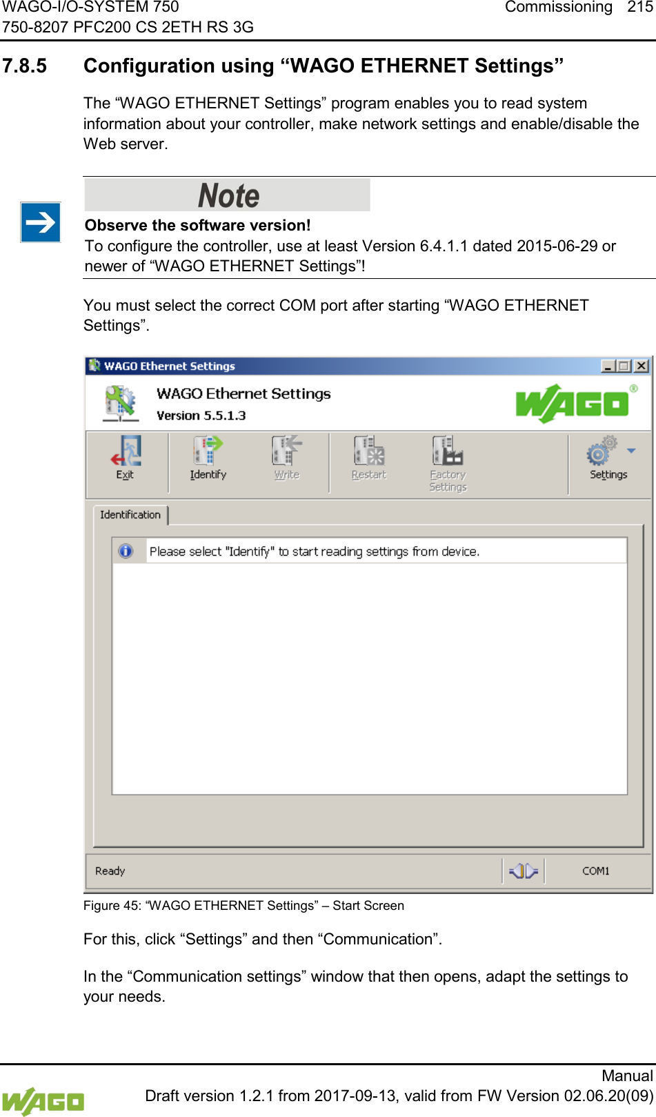
![216 Commissioning WAGO-I/O-SYSTEM 750 750-8207 PFC200 CS 2ETH RS 3G Manual Draft version 1.2.1 from 2017-09-13, valid from FW Version 02.06.20(09) Figure 46: “WAGO ETHERNET Settings” – Communication Link Once you have configured “WAGO ETHERNET Settings” and have clicked [OK], connection to the controller is established automatically. If “WAGO ETHERNET Settings” has already been started with the correct parameters, you can establish connection to the controller by clicking [Identify].](https://usermanual.wiki/WAGO-Kontakttechnik-and-KG/PFC200/User-Guide-3565964-Page-216.png)
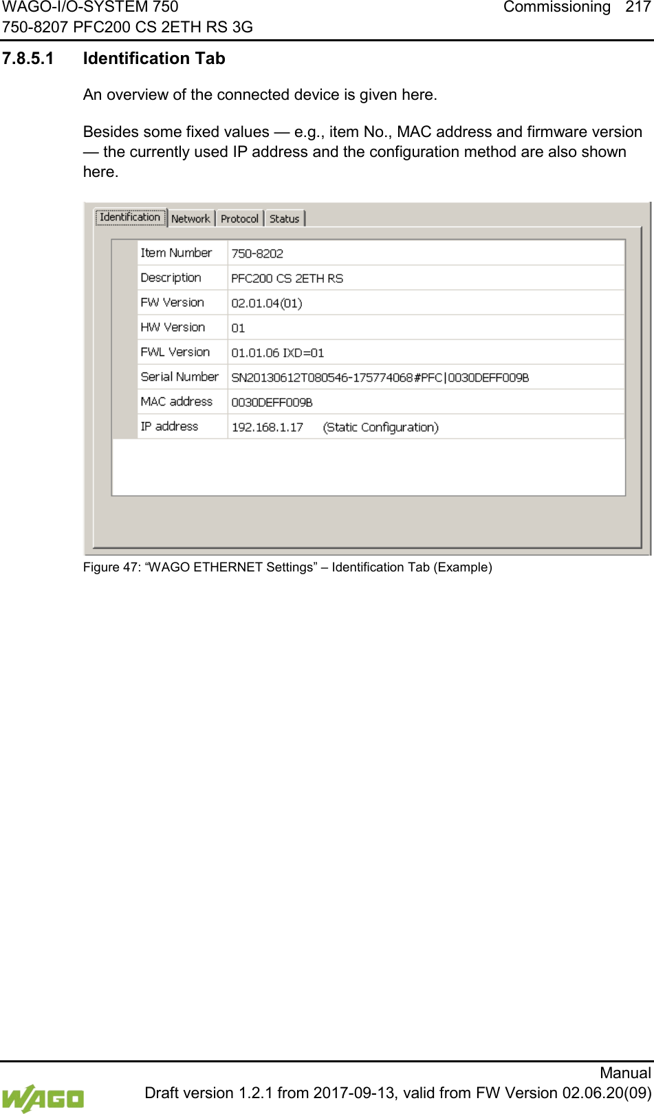
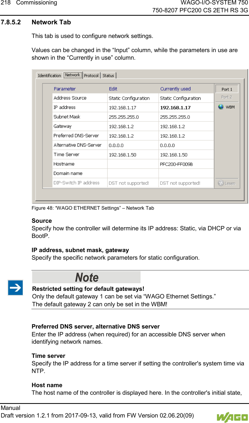
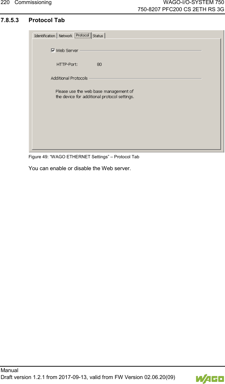
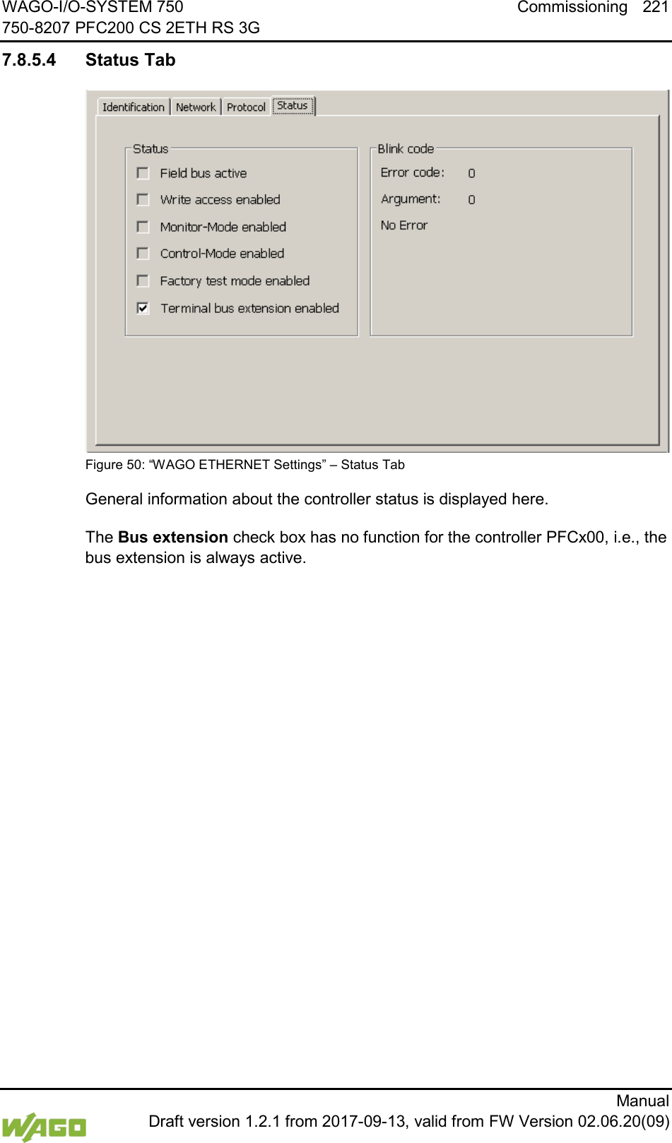
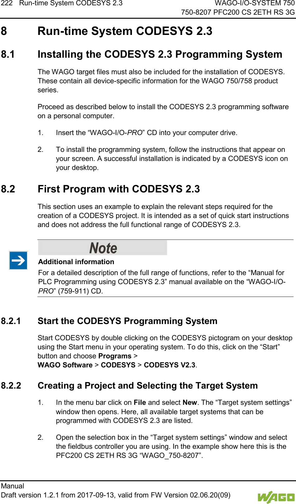
![WAGO-I/O-SYSTEM 750 Run-time System CODESYS 2.3 223 750-8207 PFC200 CS 2ETH RS 3G Manual Draft version 1.2.1 from 2017-09-13, valid from FW Version 02.06.20(09) 3. Click on [OK]. The “Target system settings” configuration window then opens. Figure 51: Target System Settings (1) 4. To accept the default configuration for the fieldbus controller click [OK]. The “New component” window opens. Figure 52: Target System Settings (2)](https://usermanual.wiki/WAGO-Kontakttechnik-and-KG/PFC200/User-Guide-3565964-Page-223.png)
![224 Run-time System CODESYS 2.3 WAGO-I/O-SYSTEM 750 750-8207 PFC200 CS 2ETH RS 3G Manual Draft version 1.2.1 from 2017-09-13, valid from FW Version 02.06.20(09) 5. In this “New component” window create a new program function block. In the example shown here, the new function block “PLC_PRG” is created in the “ST” programming language. 6. Click on [OK] to create the project. The programming interface opens. Figure 53: Creating a New Function Block Figure 54: Programming Interface with the PLC_PRG Program Module 8.2.3 Creating the PLC Configuration Procedure for Creating the PLC Configuration The procedure explained in this section describes the PLC configuration for the I/O modules connected to the controller. Information about the controller function for any fieldbuses connected to the system is given in the section on the specific fieldbus. The PLC configuration is used to configure the fieldbus controller, along with the connected I/O modules and to declare variables for accessing the inputs and outputs of the I/O modules. 1. Click on the “Resources” tab.](https://usermanual.wiki/WAGO-Kontakttechnik-and-KG/PFC200/User-Guide-3565964-Page-224.png)
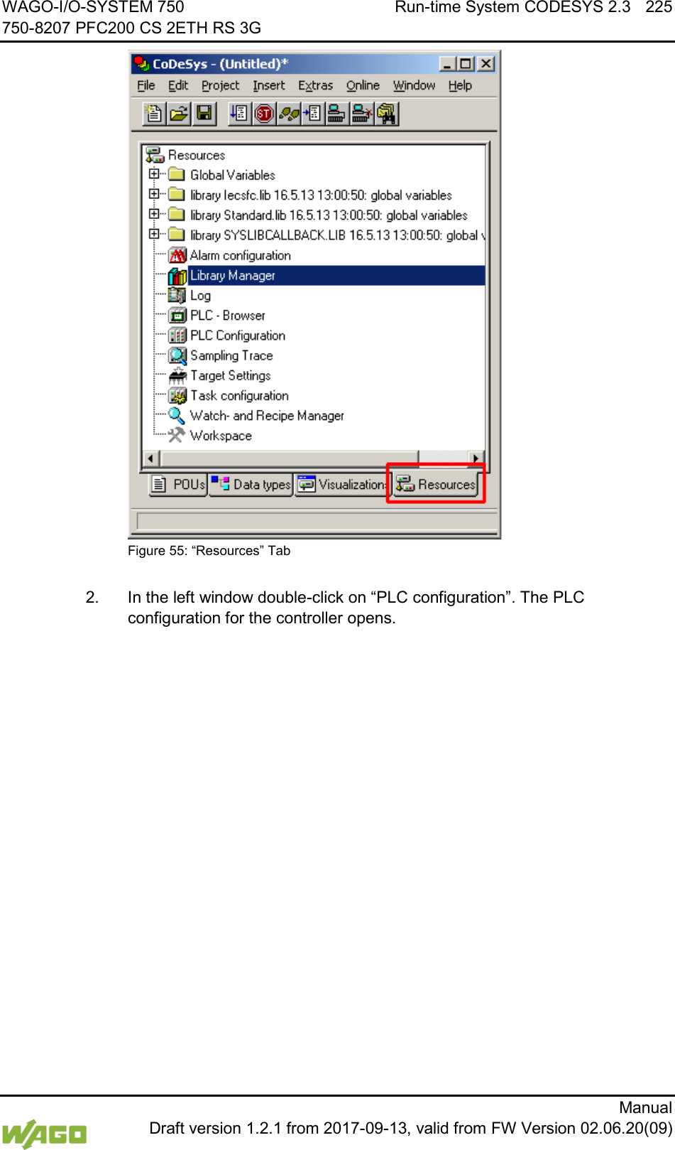
![226 Run-time System CODESYS 2.3 WAGO-I/O-SYSTEM 750 750-8207 PFC200 CS 2ETH RS 3G Manual Draft version 1.2.1 from 2017-09-13, valid from FW Version 02.06.20(09) 3. Right-click on the entry “K-Bus[FIX]” and then select “Edit” in the contextual menu. The “configuration” dialog window then opens. Figure 56: Control Configuration – Edit 4. There are three options for accepting the topology for the I/O modules connected to the fieldbus controller. The simplest way is to scan in the topology using WAGO-I/O-CHECK. To do this, click on the “Start WAGO-I/O-CHECK and scan” button. Figure 57: “Start WAGO-I/O-CHECK and Scan” Button Ensure proper installation of WAGO-I/O-CHECK! This function requires that the latest version of WAGO-I/O-CHECK be installed and the IP address set under “Online > Communication parameters”, as otherwise communication will not be possible.](https://usermanual.wiki/WAGO-Kontakttechnik-and-KG/PFC200/User-Guide-3565964-Page-226.png)
![WAGO-I/O-SYSTEM 750 Run-time System CODESYS 2.3 227 750-8207 PFC200 CS 2ETH RS 3G Manual Draft version 1.2.1 from 2017-09-13, valid from FW Version 02.06.20(09) 5. WAGO-I/O-CHECK is started. Figure 58: WAGO-I/O-CHECK – Starting Screen 6. To connect to the controller and read in the module configuration, click [Identify]. 7. If this action is successful click [Save] and exit WAGO-I/O-CHECK.](https://usermanual.wiki/WAGO-Kontakttechnik-and-KG/PFC200/User-Guide-3565964-Page-227.png)
![228 Run-time System CODESYS 2.3 WAGO-I/O-SYSTEM 750 750-8207 PFC200 CS 2ETH RS 3G Manual Draft version 1.2.1 from 2017-09-13, valid from FW Version 02.06.20(09) 8. The detected I/O modules then appear in the configuration window. Passive I/O Modules Remember that passive I/O modules, such as a power supply module (750-602) or end module (750-600) will not be shown in the I/O configurator. Figure 59: I/O Configurator Empty 9. You can use the [Add] button to add new I/O modules to manually define or change the configuration. Figure 60: “Add I/O Modules” Button](https://usermanual.wiki/WAGO-Kontakttechnik-and-KG/PFC200/User-Guide-3565964-Page-228.png)
![WAGO-I/O-SYSTEM 750 Run-time System CODESYS 2.3 229 750-8207 PFC200 CS 2ETH RS 3G Manual Draft version 1.2.1 from 2017-09-13, valid from FW Version 02.06.20(09) 10. You can select a module in the new “Module selection” window that then appears. Figure 61: “Module Selection” Window 11. You can change the position of an I/O module by marking it and then using the arrow buttons at the right edge of the window to move it up or down. Figure 62: I/O Configurator with Defined I/O Modules 12. Use [Import configuration from file] to add a configuration imported previously using WAGO-I/O-CHECK.](https://usermanual.wiki/WAGO-Kontakttechnik-and-KG/PFC200/User-Guide-3565964-Page-229.png)
![230 Run-time System CODESYS 2.3 WAGO-I/O-SYSTEM 750 750-8207 PFC200 CS 2ETH RS 3G Manual Draft version 1.2.1 from 2017-09-13, valid from FW Version 02.06.20(09) 13. To close the I/O Configurator, click [OK]. 14. The individual inputs and outputs of the selected I/O module are displayed in the right half of the configuration window. Here, you can declare a dedicated variable in the “Name” column for each input and output, e.g., “Output_1”, “Output_2”, “Input_1”, “Input_2”. Figure 63: Variable declaration 15. The added I/O modules appear in the control configuration under “K-Bus[FIX]” with their associated fixed addresses and, where applicable, their previously set variable name. Figure 64: Control Configuration: I/O Modules with Their Associated Addresses](https://usermanual.wiki/WAGO-Kontakttechnik-and-KG/PFC200/User-Guide-3565964-Page-230.png)
![WAGO-I/O-SYSTEM 750 Run-time System CODESYS 2.3 231 750-8207 PFC200 CS 2ETH RS 3G Manual Draft version 1.2.1 from 2017-09-13, valid from FW Version 02.06.20(09) 8.2.4 Editing the Program Function Block To edit the PLC_PRG program function block, go to the “Function block” tab and double-click on the PLC_PRG program module. Figure 65: Program Function Block The following example illustrates the editing of the program function block. To do this, an input is assigned to an output: 1. Press [F2] to open the Input assistant, or right click and select “Input assistant” from the contextual menu. Figure 66: Input Assistant for Selecting Variables 2. Under “Global variables” select the previously declared variable “Output_1” and click [OK] to add it. 3. Enter the allocation “=” behind the variable name.](https://usermanual.wiki/WAGO-Kontakttechnik-and-KG/PFC200/User-Guide-3565964-Page-231.png)
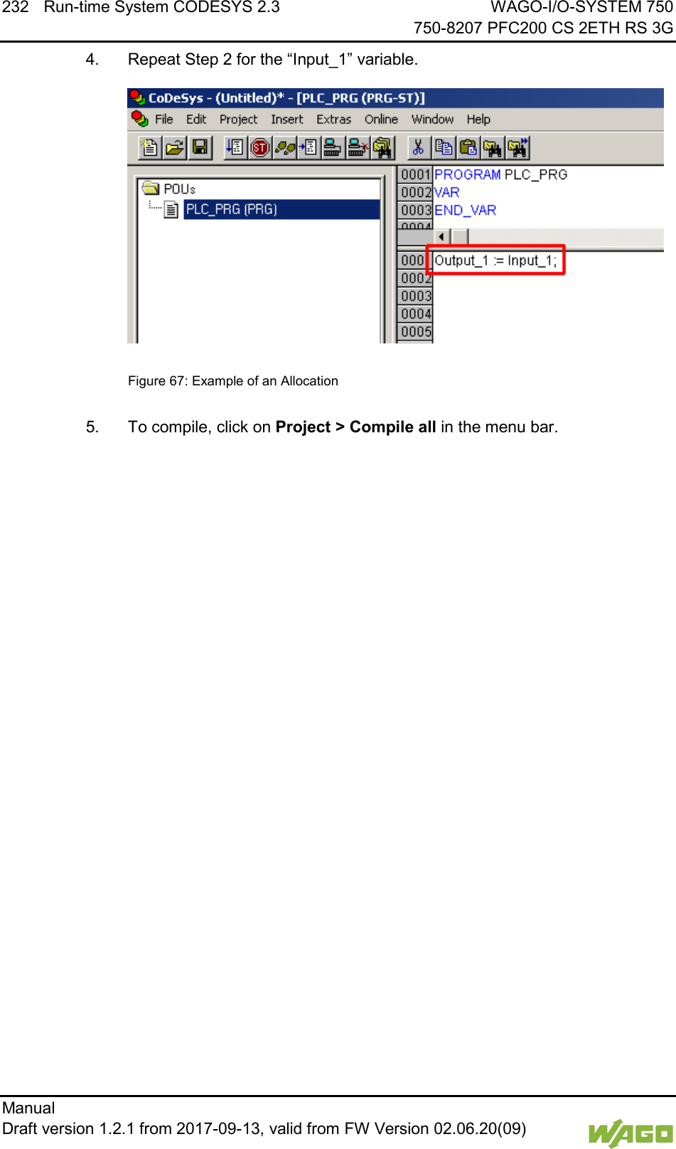
![WAGO-I/O-SYSTEM 750 Run-time System CODESYS 2.3 233 750-8207 PFC200 CS 2ETH RS 3G Manual Draft version 1.2.1 from 2017-09-13, valid from FW Version 02.06.20(09) 8.2.5 Loading and Running the PLC Program in the Fieldbus Controller (ETHERNET) Requirement: - The simulation is deactivated (Online > Simulation). - The PC is linked to the controller via ETHERNET. Refer to Section “Device Description” > …> “ETHERNET – X1, X2 Network Connection”. Proceed as follows: 1. In the menu bar click on Online and select Communication parameters …. The “Communication Parameters” window opens. 2. To select a communication link, click on [New …] in the “Communication Parameters” window. A window opens in which you can define a communication link. Figure 68: Creating a Communication Link – Step 1](https://usermanual.wiki/WAGO-Kontakttechnik-and-KG/PFC200/User-Guide-3565964-Page-233.png)
![234 Run-time System CODESYS 2.3 WAGO-I/O-SYSTEM 750 750-8207 PFC200 CS 2ETH RS 3G Manual Draft version 1.2.1 from 2017-09-13, valid from FW Version 02.06.20(09) 3. In the “Name” field enter a designation for your fieldbus controller and then click on “Tcp/Ip (Level 2 Route)”. Then click [OK]. Figure 69: Creating a Communication Link – Step 2 4. In the “Communication Parameters” window enter the IP address of your fieldbus controller in the “Address” field and then press Enter. To close the window, click on [OK]. To select an already created controller, select it in the left window and then click on [OK]. Figure 70: Creating a Communication Link – Step 3 5. Transfer the PLC program by clicking on Online in the menu bar and select Login. 6. Ensure that the Run/Stop switch for the fieldbus controller is set to “Run”. 7. Start the PLC program by clicking on Online > Start in the menu bar.](https://usermanual.wiki/WAGO-Kontakttechnik-and-KG/PFC200/User-Guide-3565964-Page-234.png)
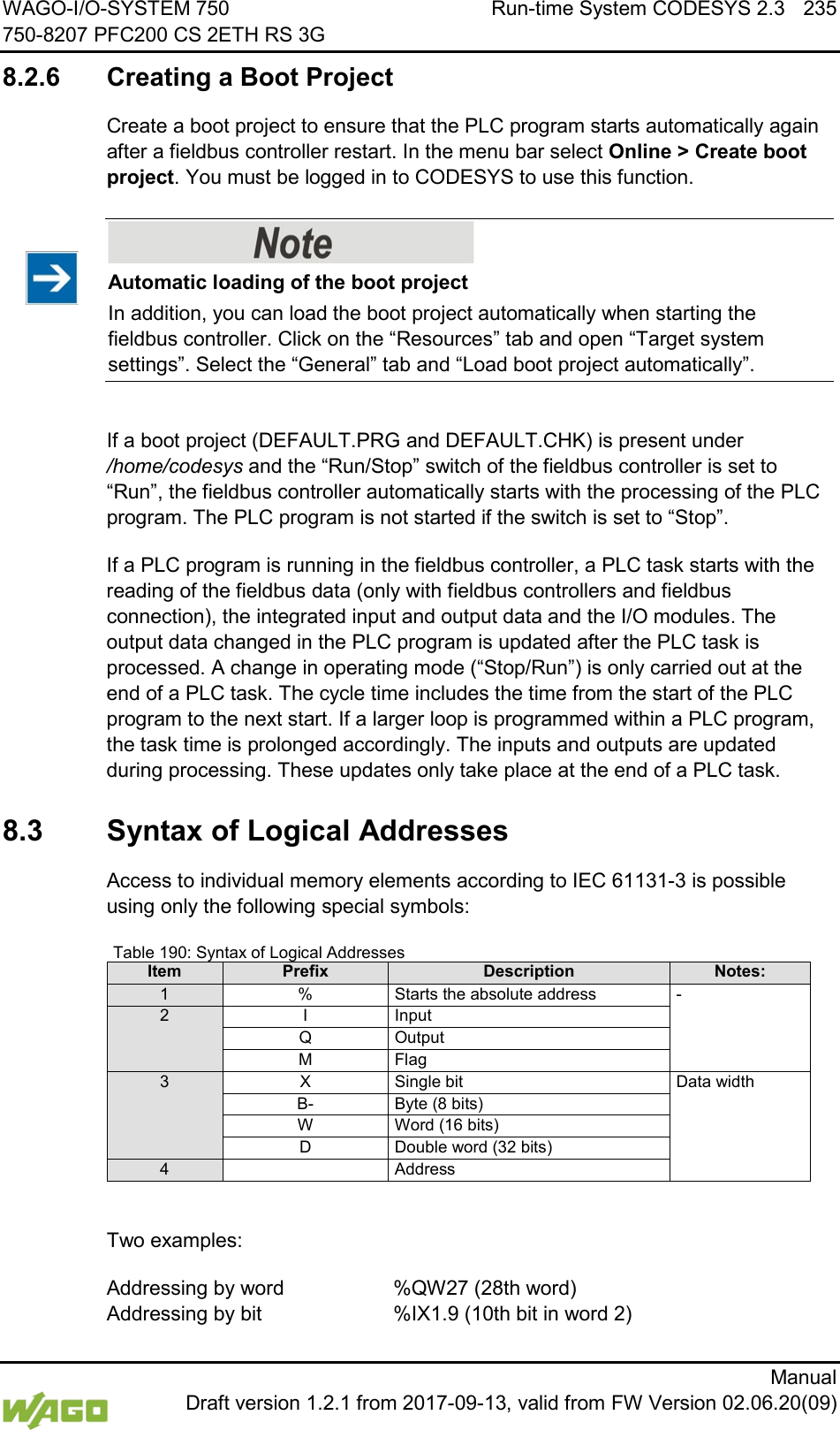
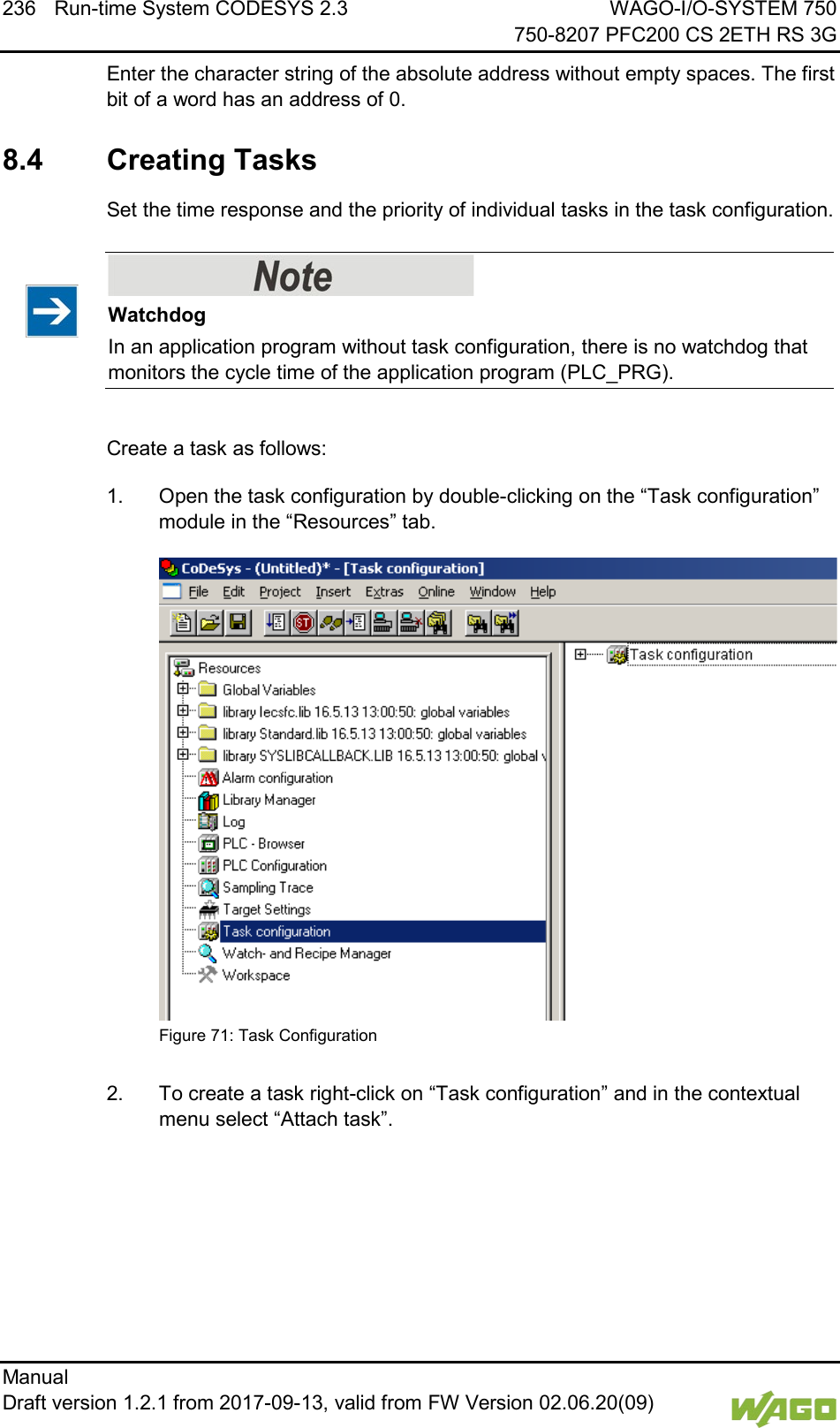
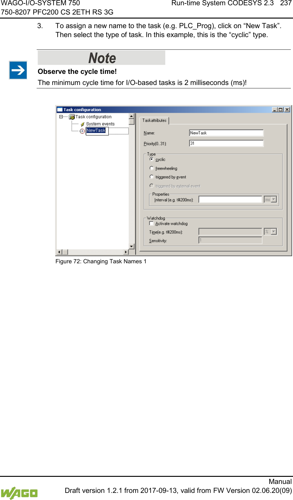
![238 Run-time System CODESYS 2.3 WAGO-I/O-SYSTEM 750 750-8207 PFC200 CS 2ETH RS 3G Manual Draft version 1.2.1 from 2017-09-13, valid from FW Version 02.06.20(09) 4. Add the program module PLC_PRG that you have just created (see Section “Editing the Program Modules”). To do this, right-clock on the “Clock” symbol and in the contextual menu select “Attach program call-up”. Then, click the [...] button and [OK]. Figure 73: Call-up to Add to the Program Module 5. Compile the example program by selecting Project > Rebuild all in the context menu.](https://usermanual.wiki/WAGO-Kontakttechnik-and-KG/PFC200/User-Guide-3565964-Page-238.png)
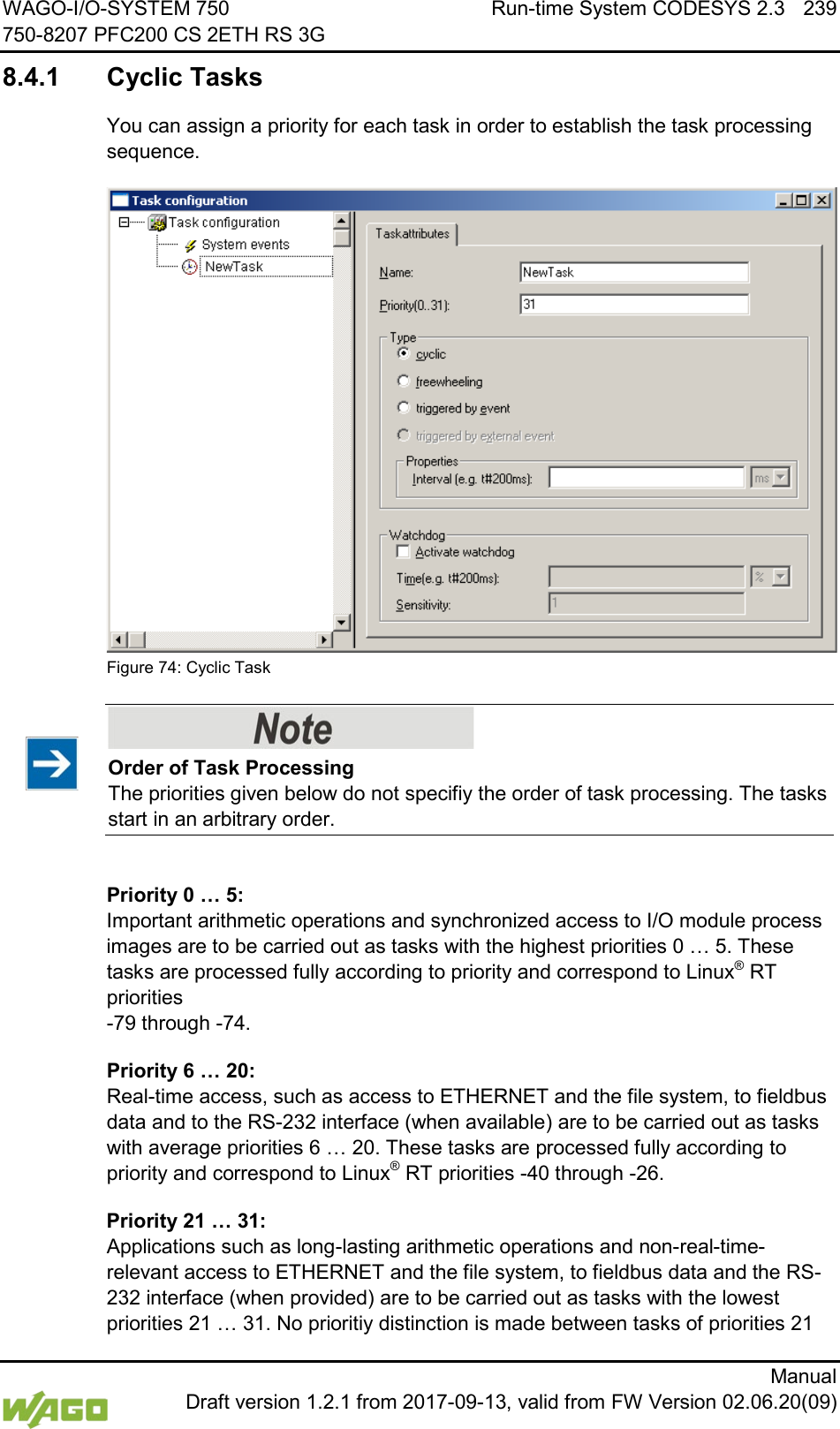
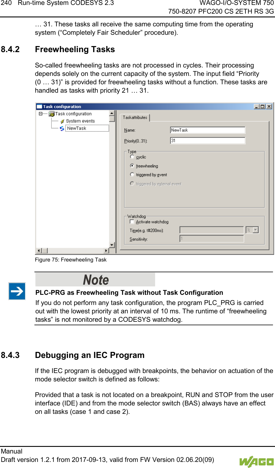
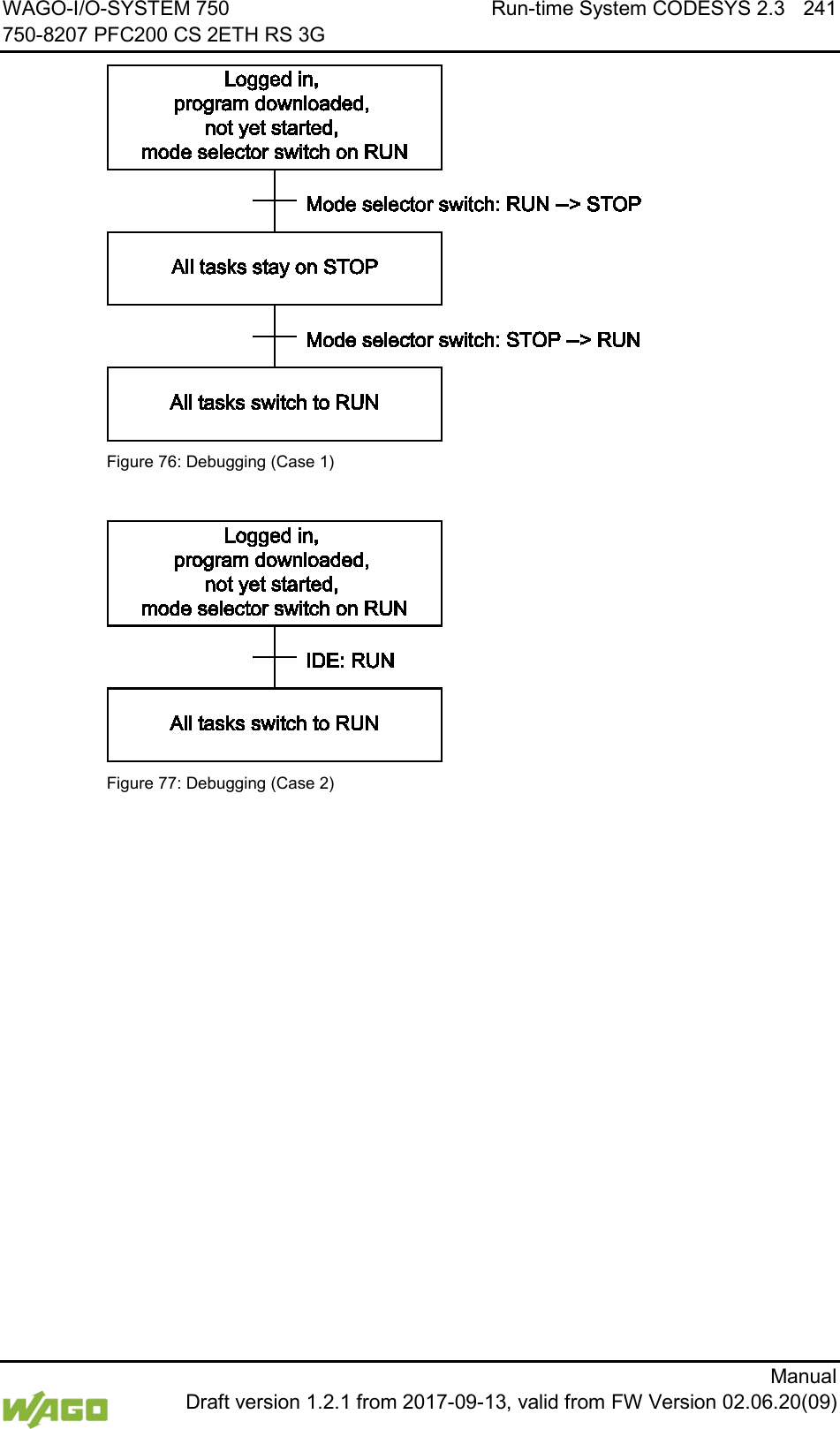
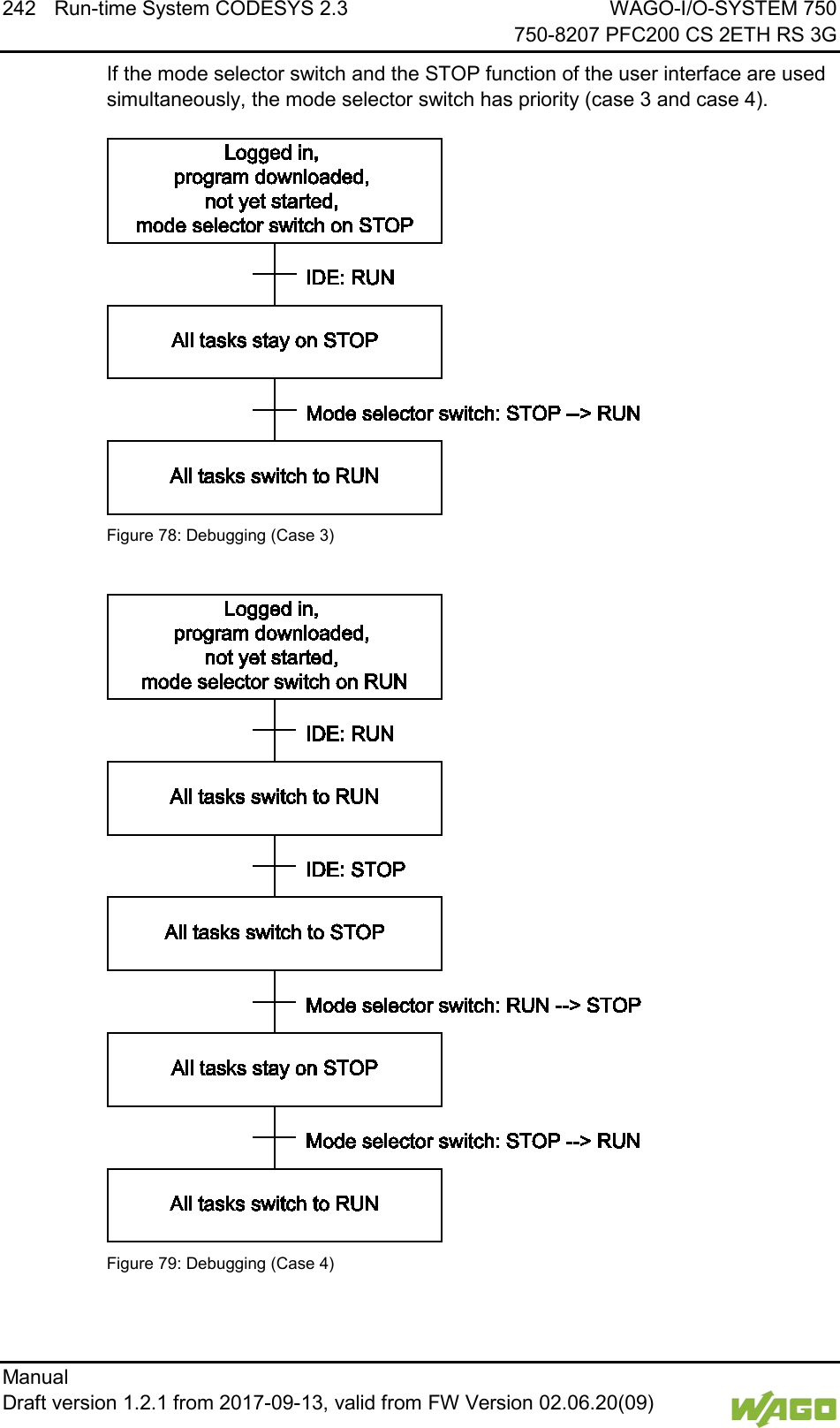
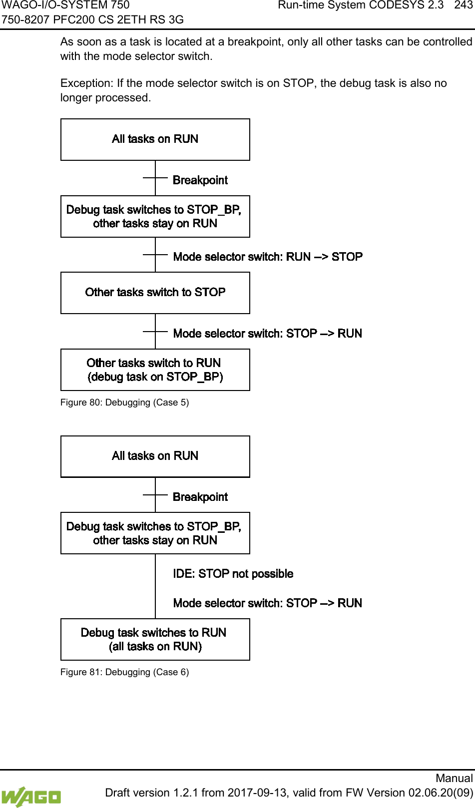
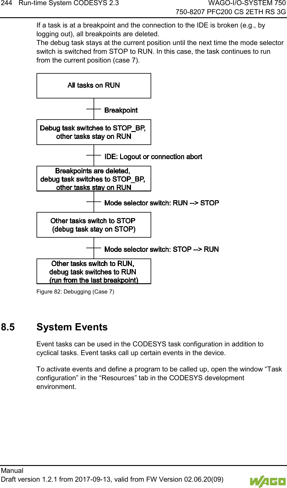
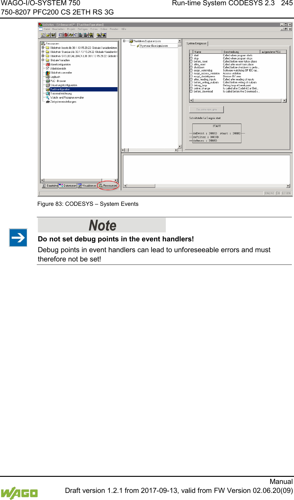
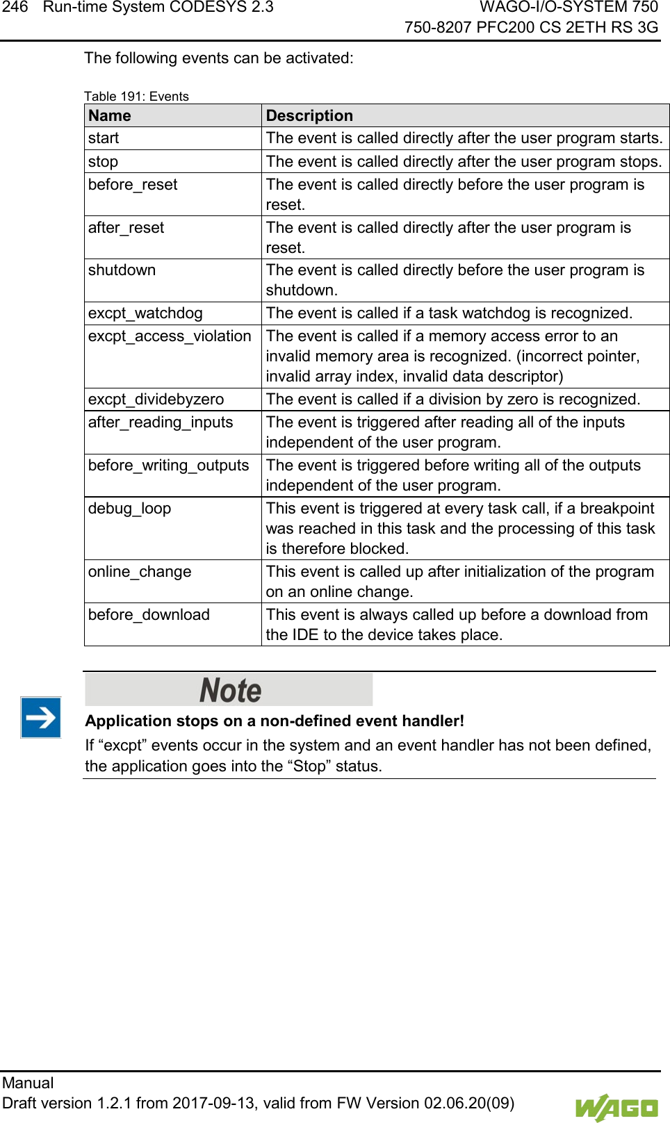
![WAGO-I/O-SYSTEM 750 Run-time System CODESYS 2.3 247 750-8207 PFC200 CS 2ETH RS 3G Manual Draft version 1.2.1 from 2017-09-13, valid from FW Version 02.06.20(09) 8.5.1 Creating an Event Handler The example here is provided to illustrate how to define and use an event handler. The event handler “excpt_dividebyzero” is used in this example. First, a program is generated in the PLC_PRG- module which provokes division by 0. Figure 84: CODESYS Program Provokes Division by “0” After this, the system event “excpt_dividebyzero” is activated in the Task Configurator and the name of the event handler to be generated is entered in the column “Called POU”. Figure 85: CODESYS – Creating and Activating an Event Handler To generate the event handler, click [Generate CALLBACK_DIV_BY_ZERO function block]. A new function having the defined name then appears in the “Function blocks” tab.](https://usermanual.wiki/WAGO-Kontakttechnik-and-KG/PFC200/User-Guide-3565964-Page-247.png)
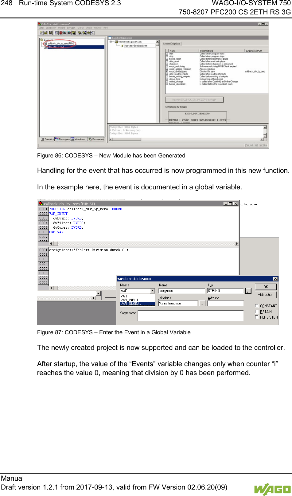
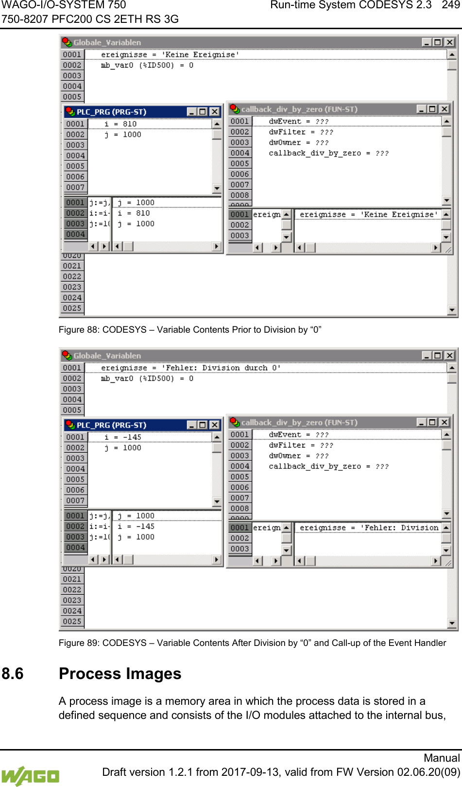
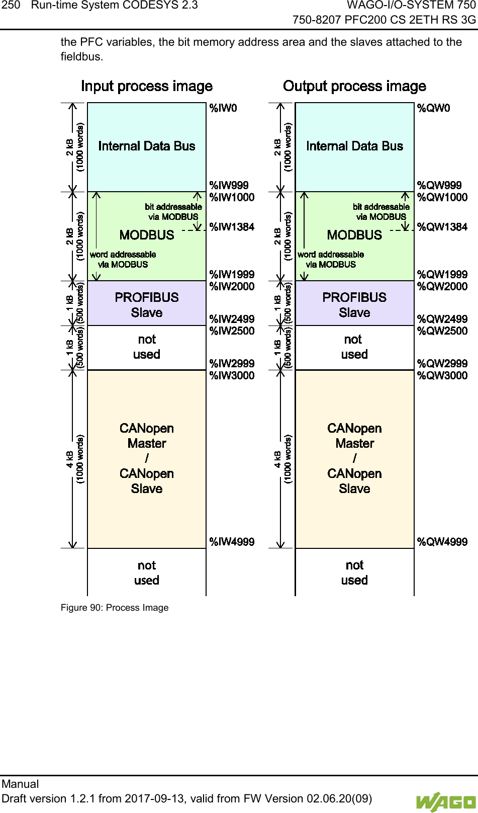
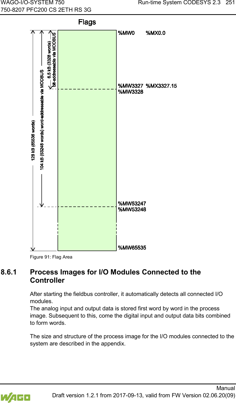
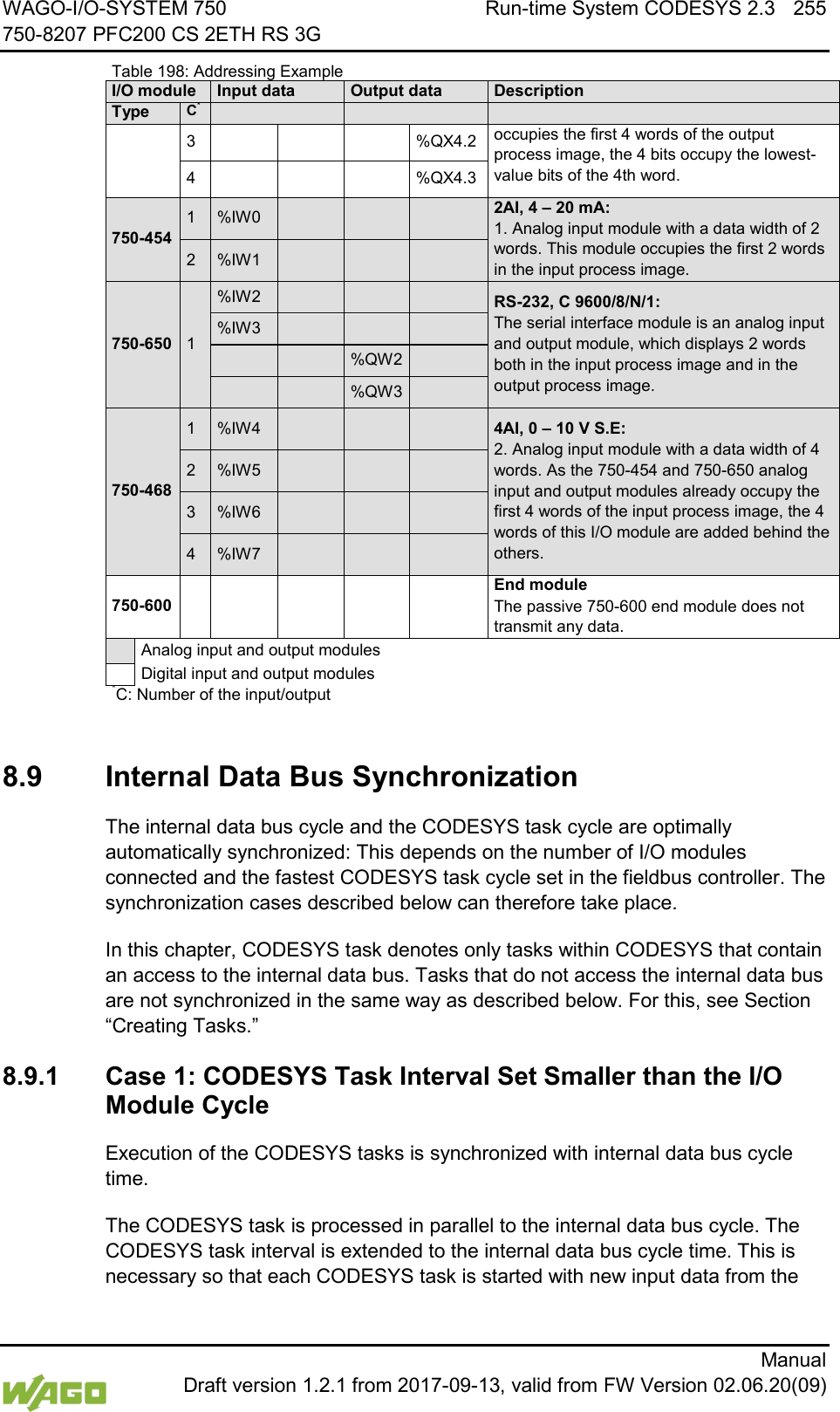
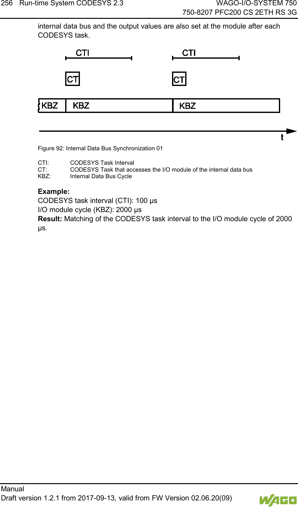
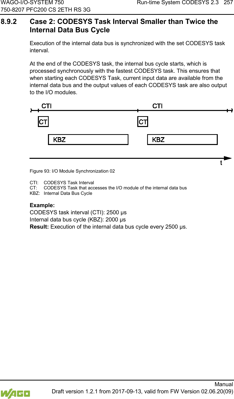
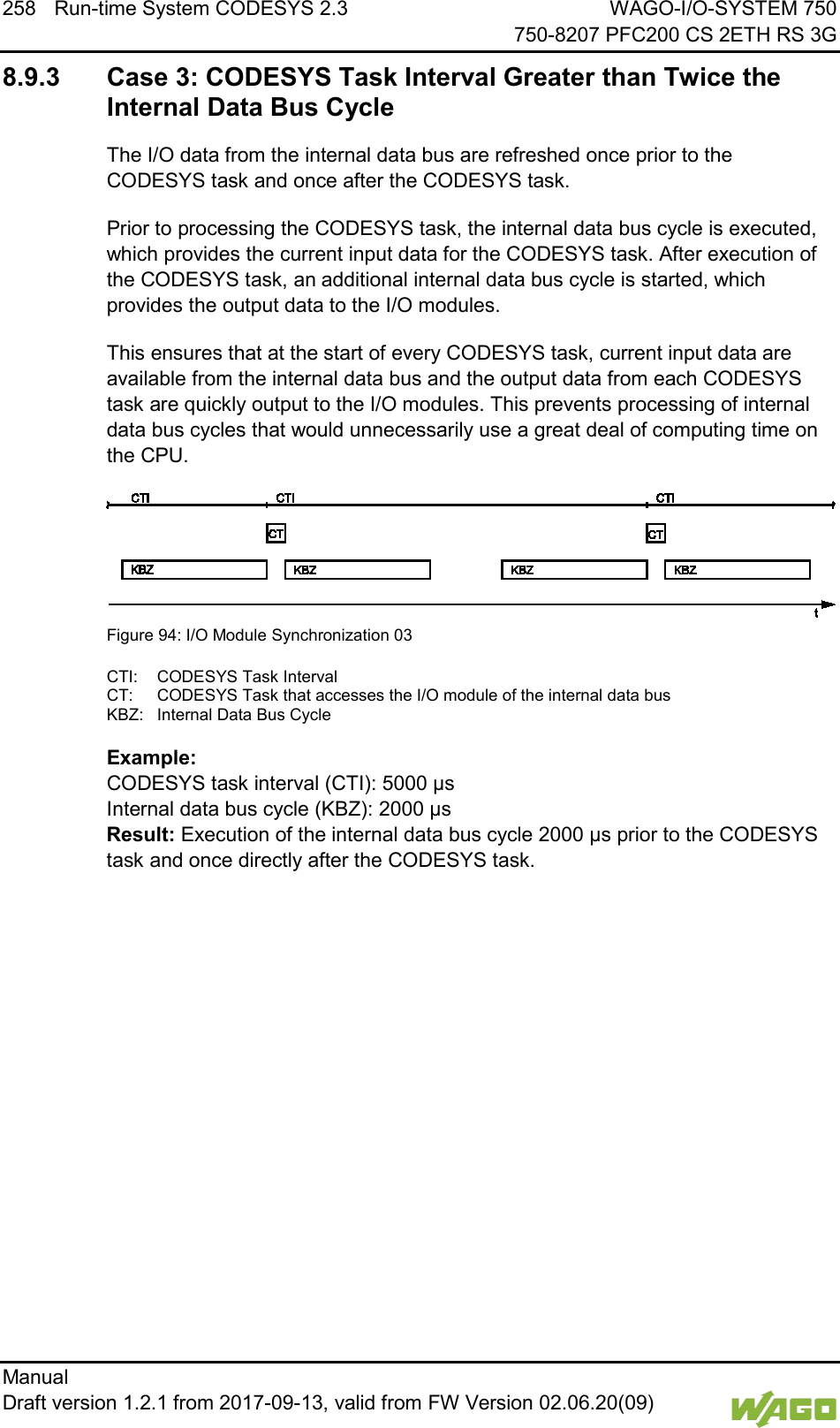
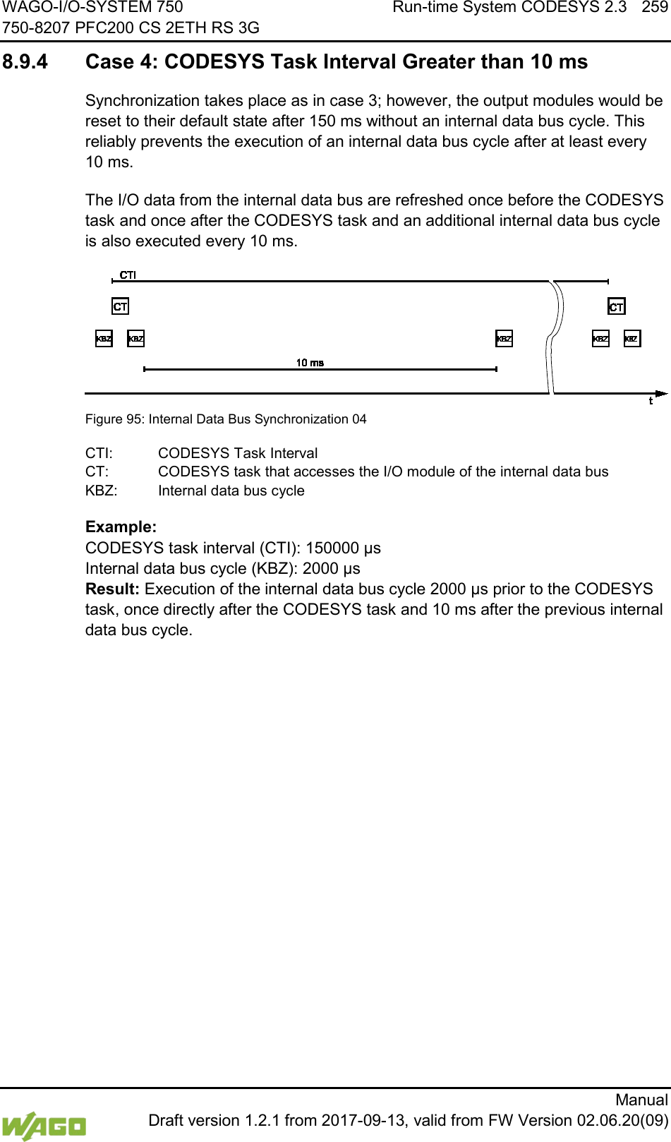
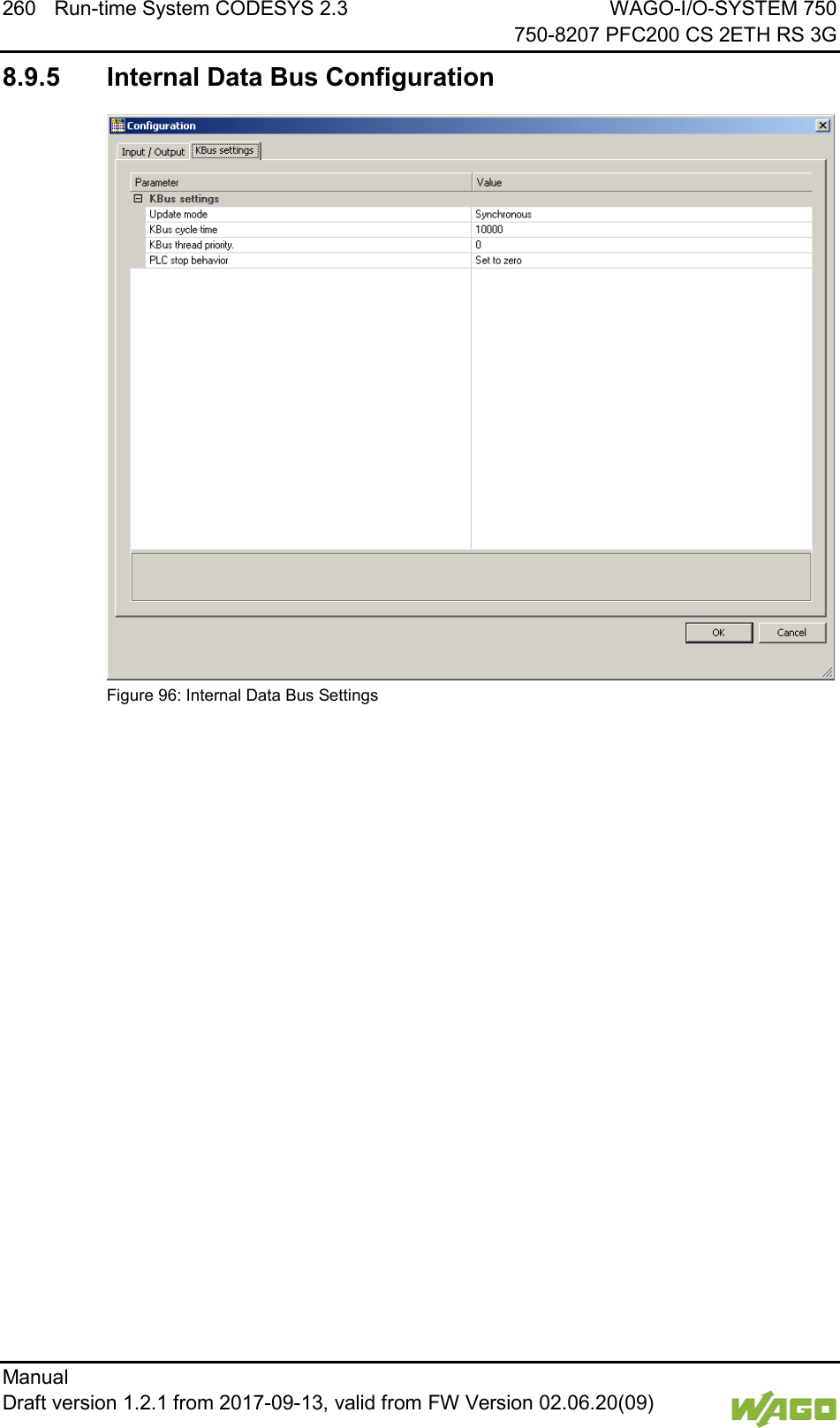
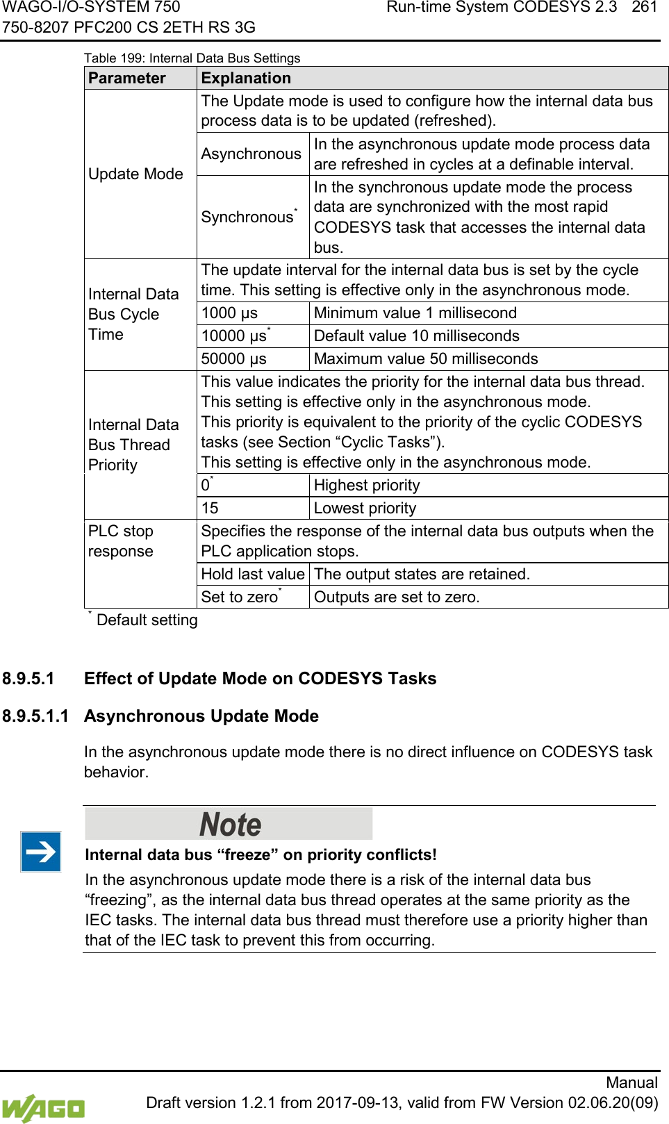
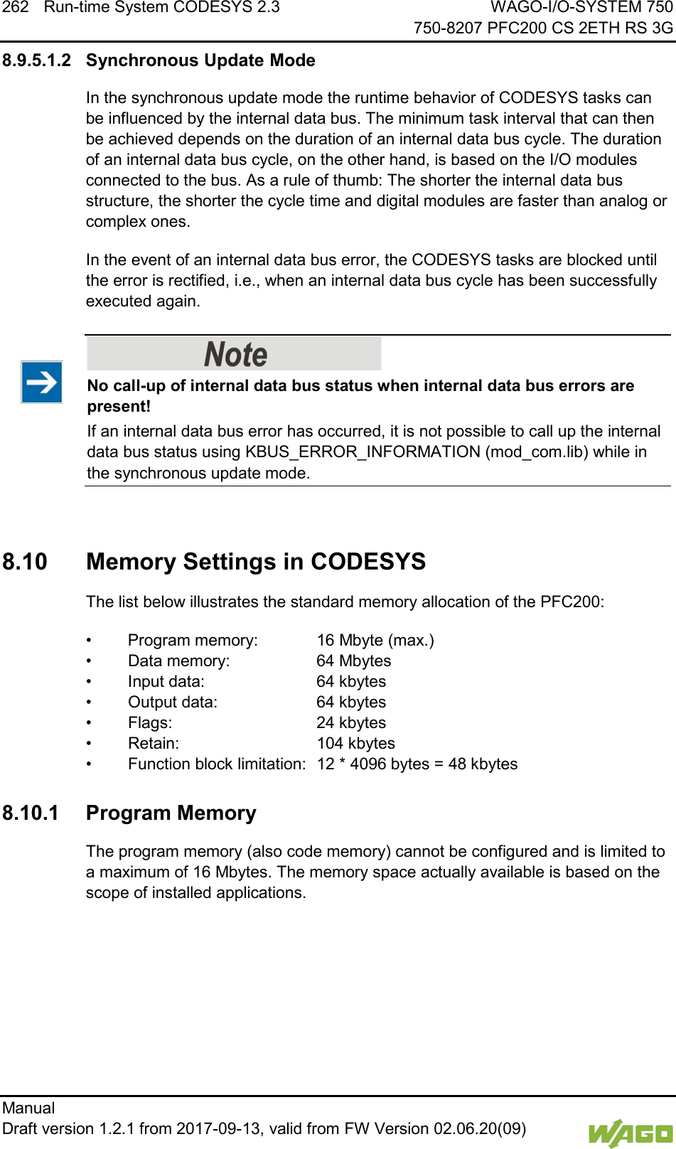
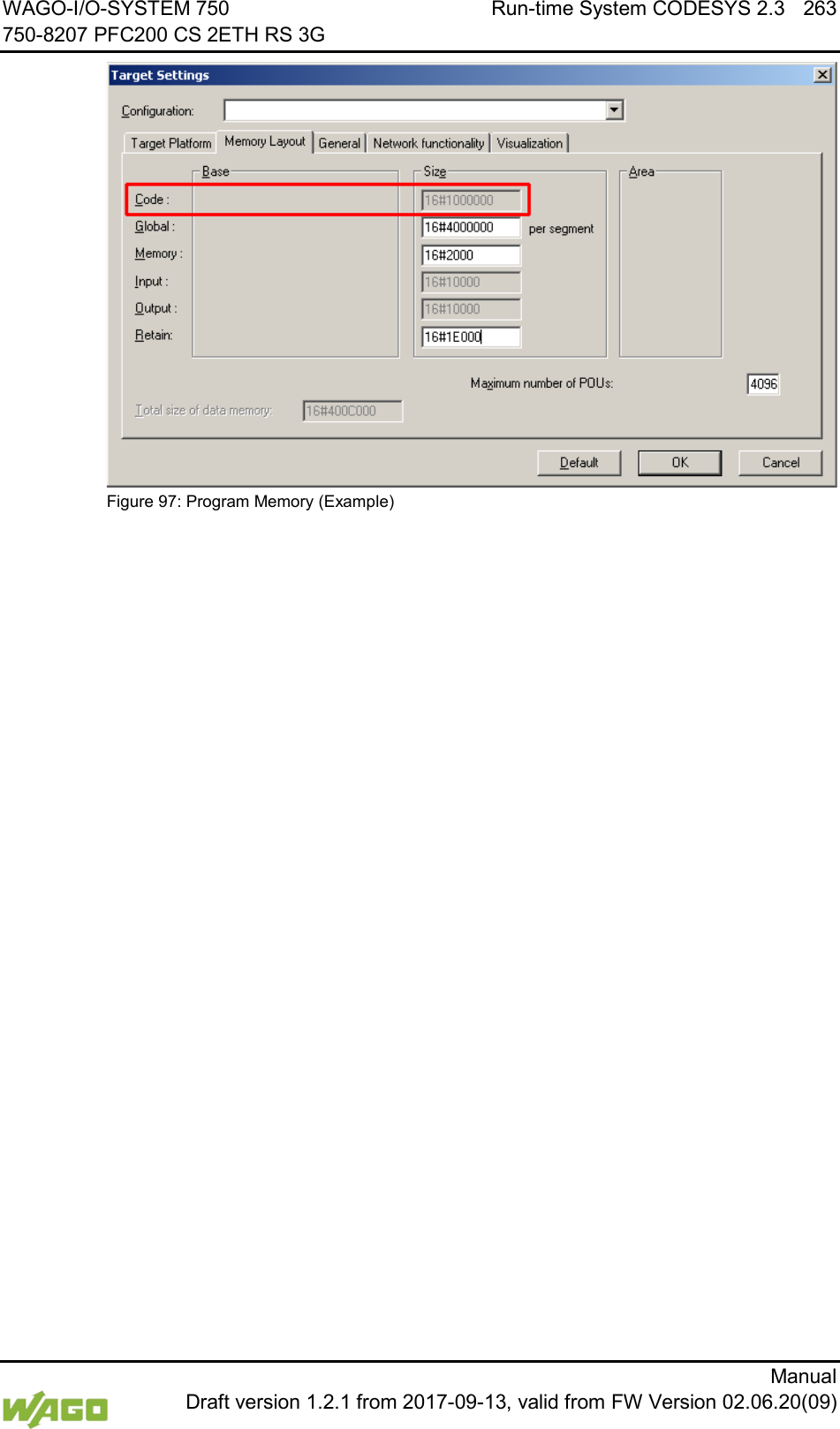
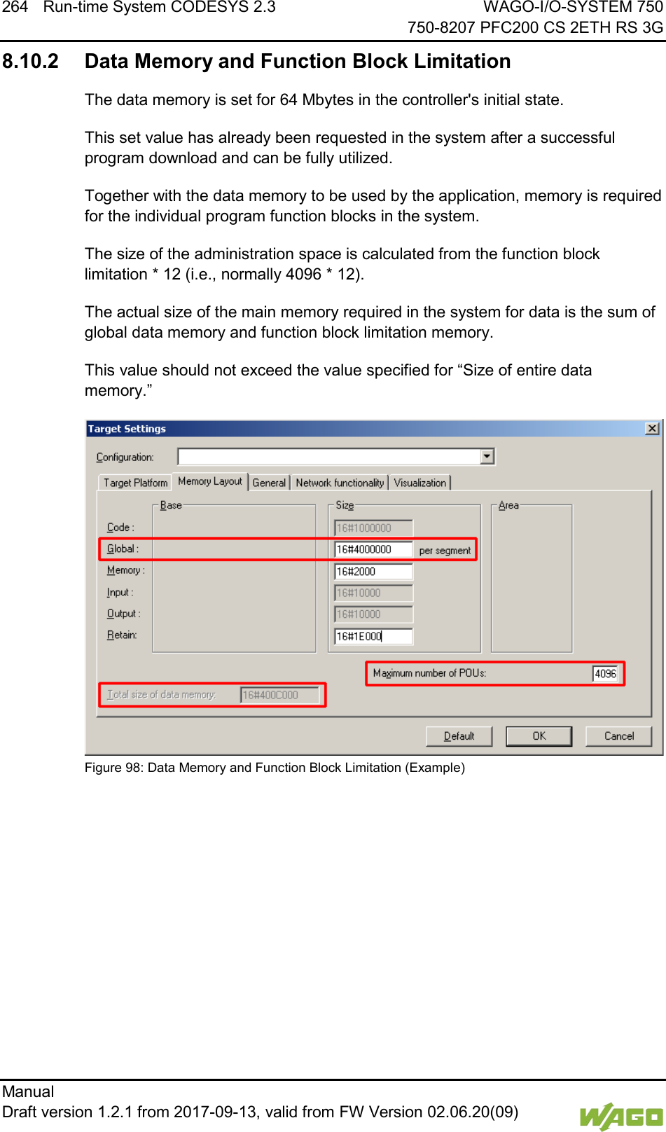
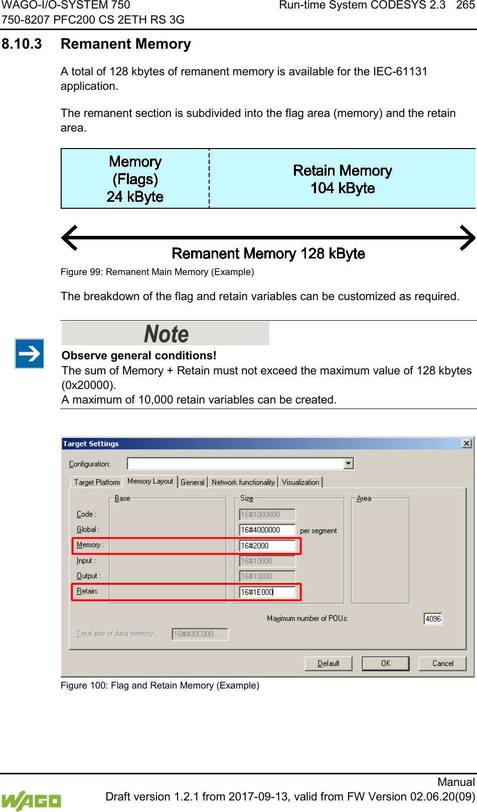
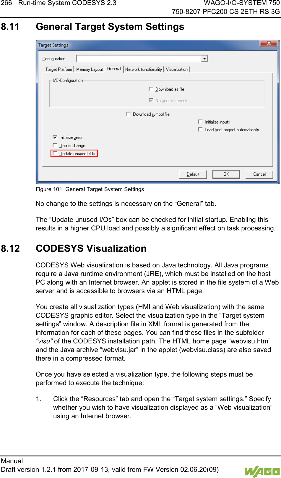
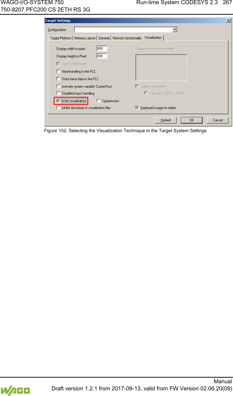
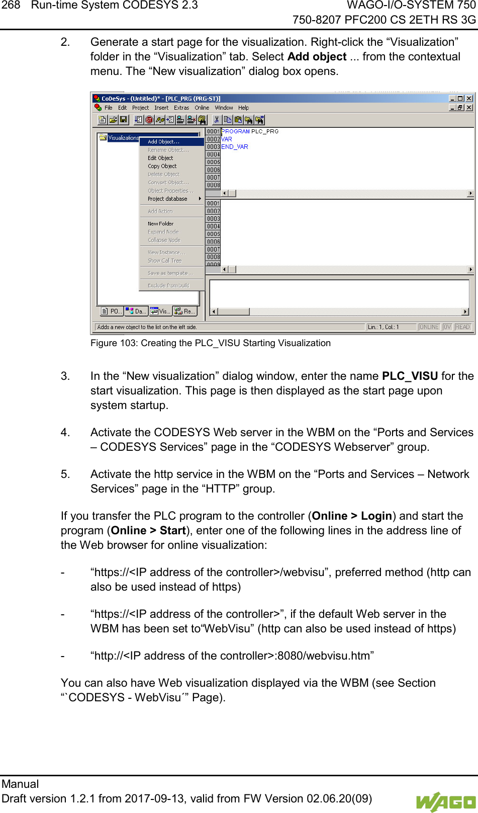
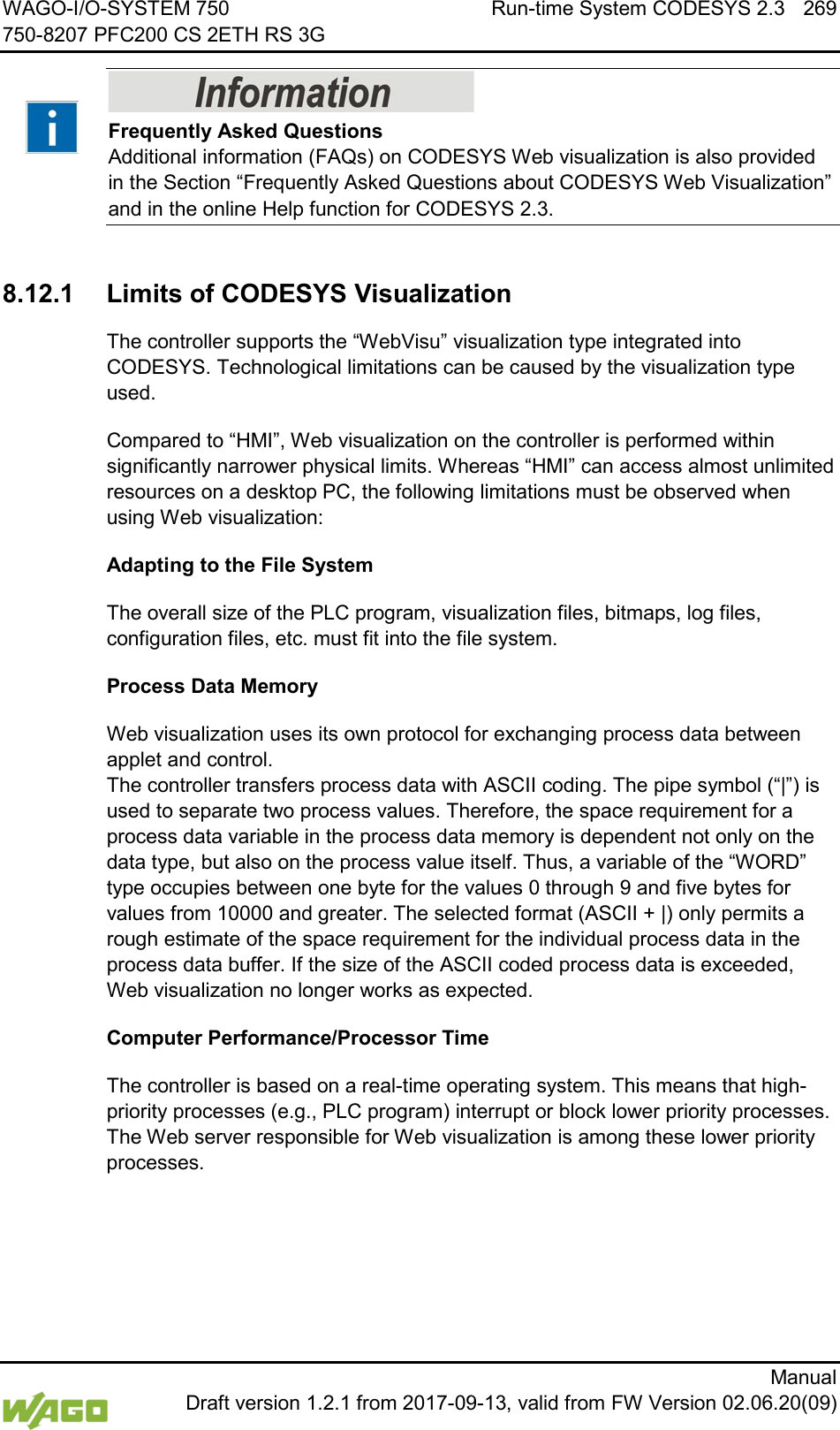
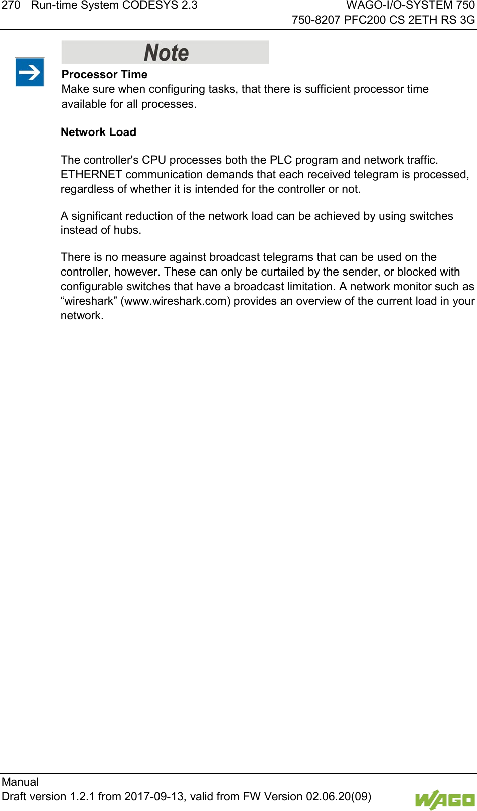
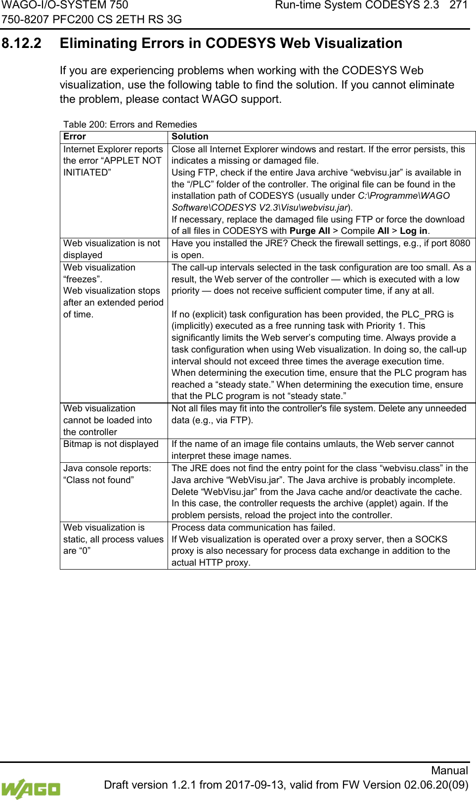
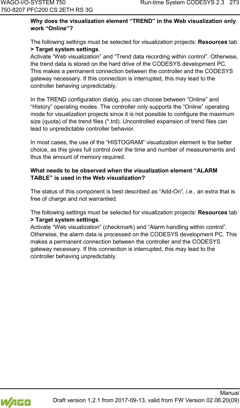
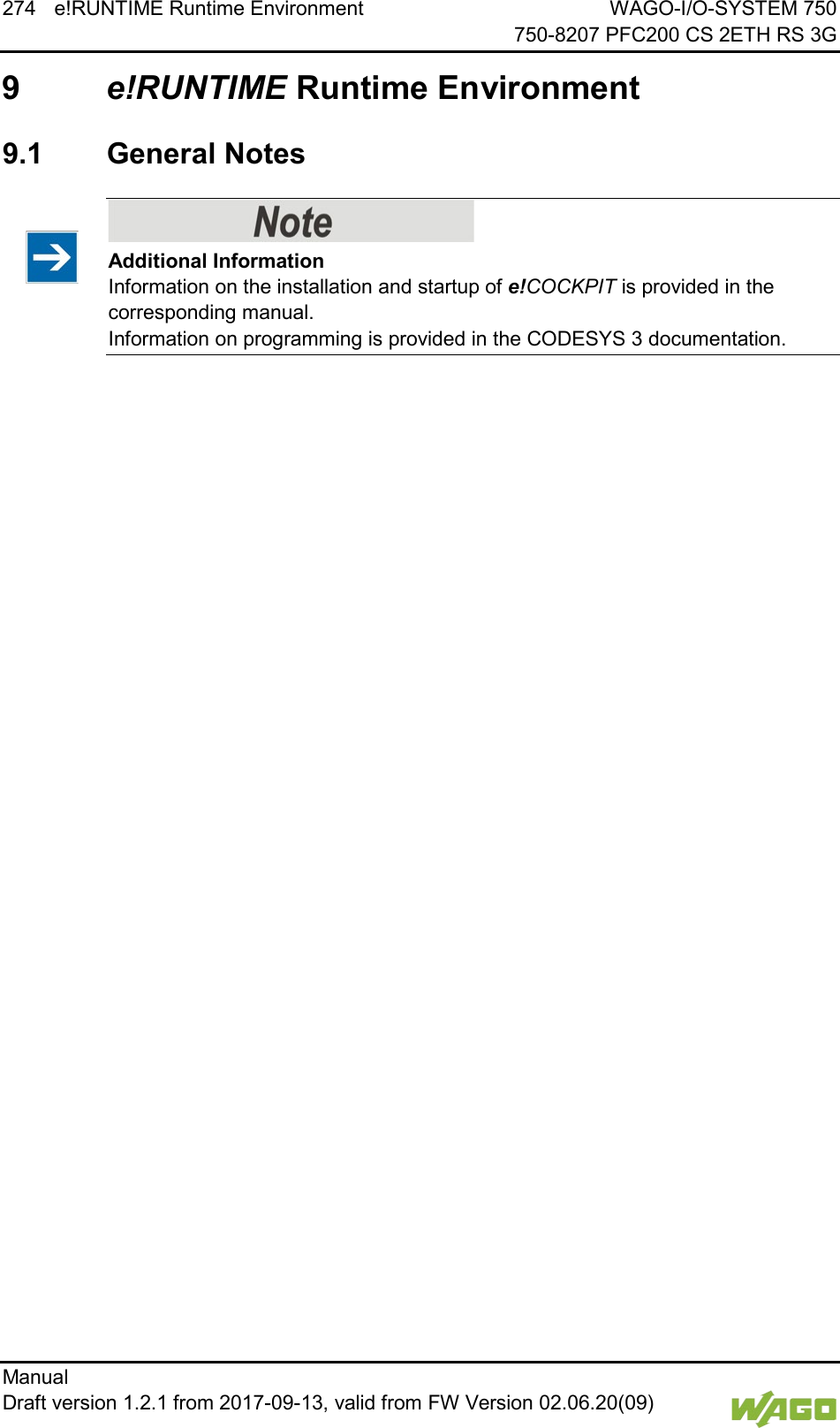
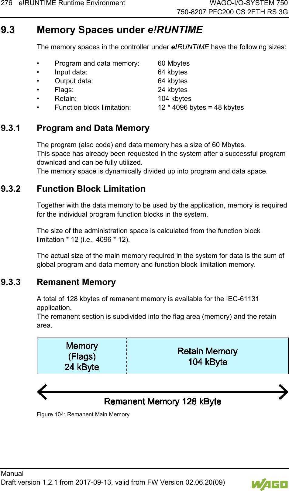
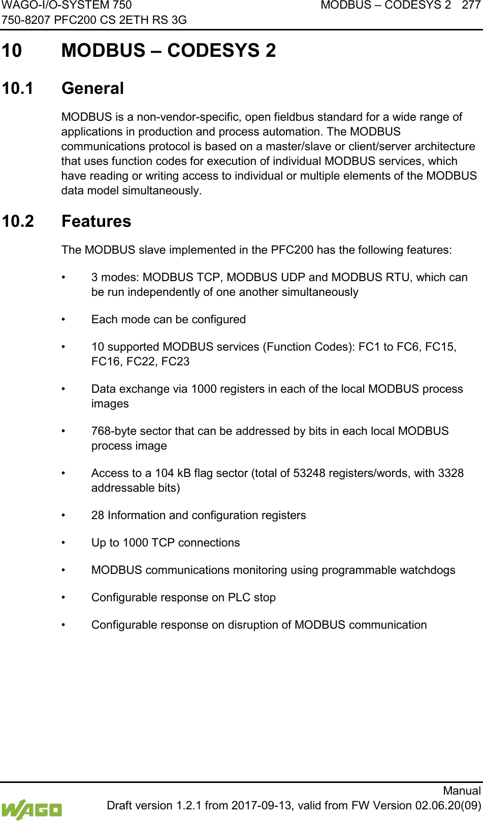
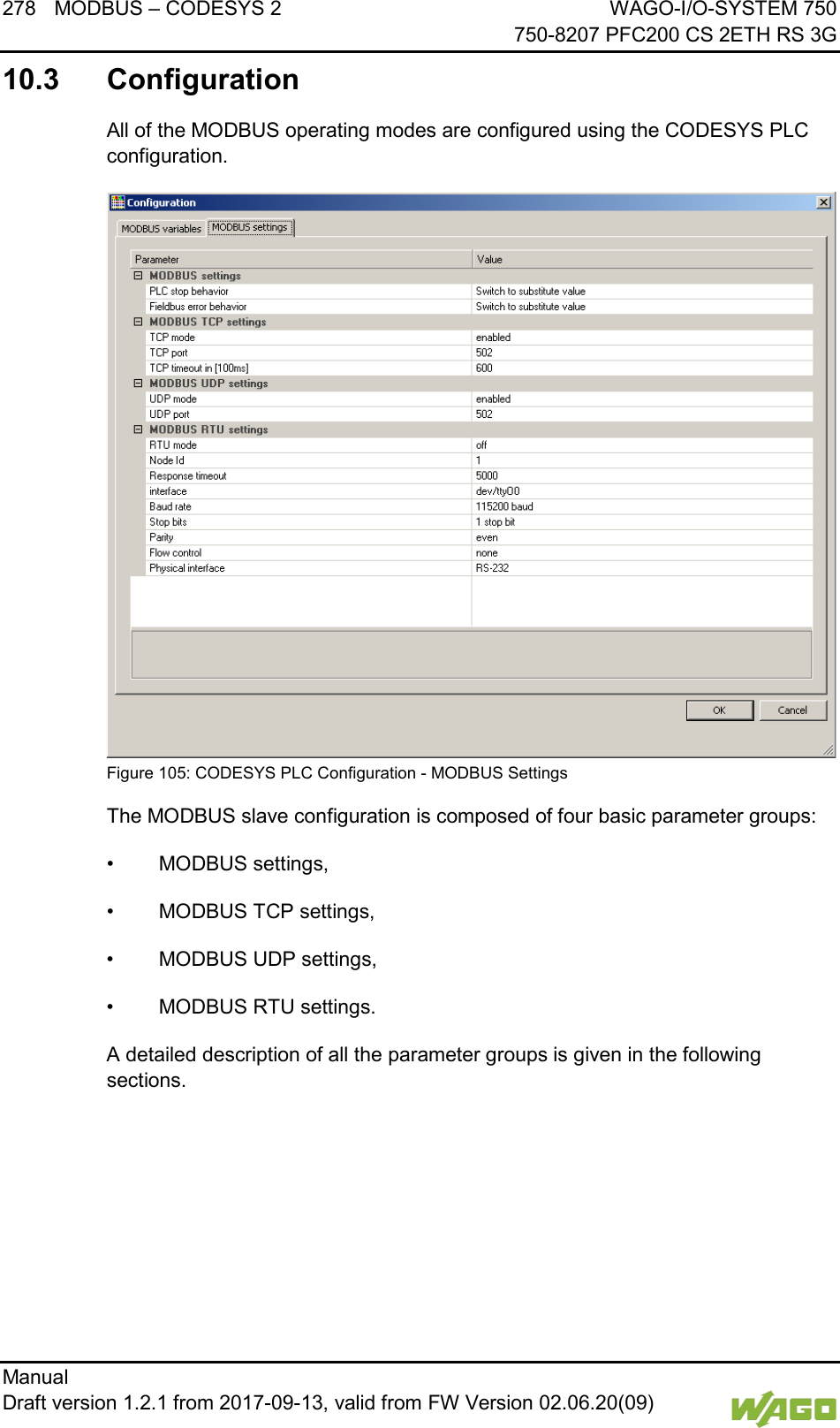
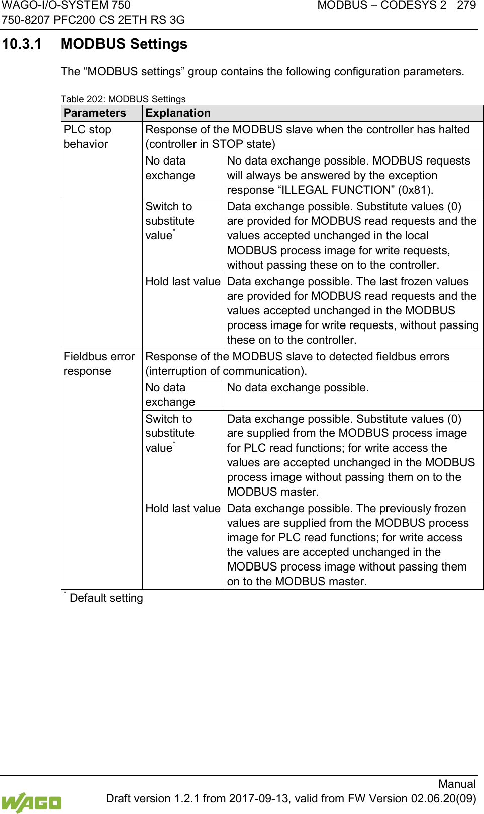
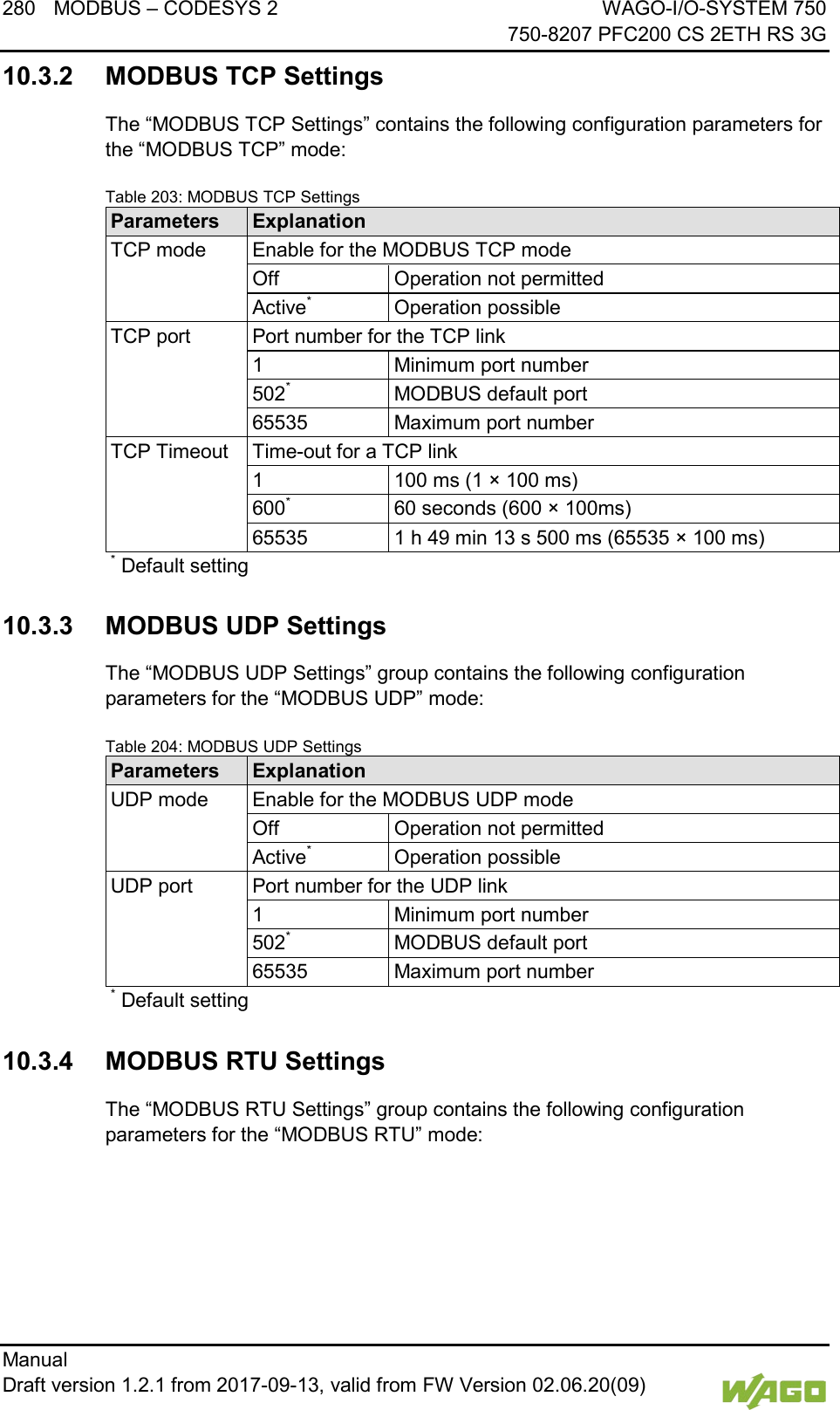
![WAGO-I/O-SYSTEM 750 MODBUS – CODESYS 2 281 750-8207 PFC200 CS 2ETH RS 3G Manual Draft version 1.2.1 from 2017-09-13, valid from FW Version 02.06.20(09) Table 205: MODBUS RTU Settings Parameters Explanation RTU mode Enable for the MODBUS RTU mode Off* Operation not permitted Active Operation possible Device ID Device ID (device address) for the tty device 1* min. device ID 247 max. device ID Maximum response time Response timeout for a request in [ms] 2000 min. response time = 2 seconds. If this value is set lower than 2 seconds, it will be corrected internally to 2 seconds. 5000* Default = 5 seconds 4294967295 max. response time > 71 hours. Interface Device name “dev/…” Name of the tty in the string “dev/ttyO0”* Standard tty Baud rate Communication baud rate 1200 baud 1200 baud min. transmission speed 2400 baud 2400 baud 4800 baud 4800 baud 9600 baud 9600 baud 19200 baud 19200 baud 38400 baud 38400 baud 57600 baud 57600 baud 115200 baud* 115200 baud, max. transmission speed Stop bits Number of stop bits 1 stop bit* 1 stop bit in the frame; must be used when even or odd parity has been selected. 2 stop bits 2 stop bits in the frame; must be used when “None” has been selected for parity. Parity Parity check None No parity check performed; 2 stop bits must be selected in the configuration for this setting. Even* Even parity Odd Odd parity](https://usermanual.wiki/WAGO-Kontakttechnik-and-KG/PFC200/User-Guide-3565964-Page-281.png)