WAGO Kontakttechnik and KG PFC200 3G PLC Controller User Manual Manual 750 8207
WAGO Kontakttechnik GmbH & Co. KG 3G PLC Controller Manual 750 8207
Users Manual
Manual
WAGO-I/O-SYSTEM 750
750-8207(/xxx-xxx)
PFC200 CS 2ETH RS 3G
PLC
- Controller PFC200
Draft version 1.2.1 from 2017-09-13, valid from FW Version 02.06.20(09)

2 WAGO-I/O-SYSTEM 750
750-8207 PFC200 CS 2ETH RS 3G
Manual
Draft version 1.2.1 from 2017-09-13, valid from FW Version 02.06.20(09)
© 2017 WAGO Kontakttechnik GmbH & Co. KG
All rights reserved.
WAGO Kontakttechnik GmbH & Co. KG
Hansastraße 27
D-32423 Minden
Phone: +49 (0) 571/8 87 – 0
Fax: +49 (0) 571/8 87 – 1 69
E-Mail: info@wago.com
Web: http://www.wago.com
Technical Support
Phone: +49 (0) 571/8 87 – 5 55
Fax: +49 (0) 571/8 87 – 85 55
E-Mail: support@wago.com
Every conceivable measure has been taken to ensure the accuracy and
completeness of this documentation. However, as errors can never be fully
excluded, we always appreciate any information or suggestions for improving the
documentation.
E-Mail: documentation@wago.com
We wish to point out that the software and hardware terms as well as the
trademarks of companies used and/or mentioned in the present manual are
generally protected by trademark or patent.
WAGO is a registered trademark of WAGO Verwaltungsgesellschaft mbH.

WAGO-I/O-SYSTEM 750 Table of Contents 3
750-8207 PFC200 CS 2ETH RS 3G
Manual
Draft version 1.2.1 from 2017-09-13, valid from FW Version 02.06.20(09)
Table of Contents
1 Notes about this Documentation ........................................................... 15
1.1 Validity of this Documentation............................................................... 15
1.2 Copyright .............................................................................................. 15
1.3 Symbols ............................................................................................... 16
1.4 Number Notation .................................................................................. 18
1.5 Font Conventions ................................................................................. 18
2 Important Notes ...................................................................................... 19
2.1 Legal Bases .......................................................................................... 19
2.1.1 Subject to Changes .......................................................................... 19
2.1.2 Personnel Qualifications .................................................................. 19
2.1.3 Use of the WAGO-I/O-SYSTEM 750 in Compliance with Underlying
Provisions ........................................................................................ 19
2.1.4 Technical Condition of Specified Devices......................................... 20
2.2 Safety Advice (Precautions) ................................................................. 21
2.3 Disclaimer............................................................................................. 22
2.4 Licensing Terms of the Software Package Used................................... 23
2.5 Special Use Conditions for ETHERNET Devices .................................. 23
3 Device Description .................................................................................. 24
3.1 View ..................................................................................................... 27
3.2 Labeling ................................................................................................ 29
3.2.1 Manufacturing Number ..................................................................... 29
3.3 Connectors ........................................................................................... 30
3.3.1 Data Contacts/Internal Bus .............................................................. 30
3.3.2 Power Jumper Contacts/Field Supply .............................................. 31
3.3.3 CAGE CLAMP® Connectors ............................................................. 32
3.3.4 Service Interface .............................................................................. 33
3.3.5 Network Connections – X1, X2 ........................................................ 34
3.3.6 RS-232/RS-485 – X3 Communication Connection ........................... 35
3.3.6.1 Operating as an RS-232 Interface ............................................... 36
3.3.6.2 Operating as an RS-485 Interface ............................................... 37
3.3.7 Mobile Radio Antenna ...................................................................... 38
3.4 Display Elements .................................................................................. 39
3.4.1 Power Supply Indicating Elements ................................................... 39
3.4.2 Fieldbus/System Indicating Elements ............................................... 40
3.4.3 Memory Card Indicating Elements ................................................... 41
3.4.4 Network Indicating Elements ............................................................ 42
3.4.5 Mobile Radio Network Status Indicators ........................................... 43
3.5 Operating Elements .............................................................................. 44
3.5.1 Operating Mode Switch .................................................................... 44
3.5.1.1 CODESYS 2 Runtime System ..................................................... 44
3.5.1.2 e!RUNTIME Runtime System ...................................................... 44
3.5.2 Reset Button .................................................................................... 45
3.6 Slot for Memory Card ........................................................................... 46
3.7 SIM Card Slot ....................................................................................... 47
3.8 Schematic Diagram .............................................................................. 48
3.9 Technical Data ..................................................................................... 49

4 Table of Contents WAGO-I/O-SYSTEM 750
750-8207 PFC200 CS 2ETH RS 3G
Manual
Draft version 1.2.1 from 2017-09-13, valid from FW Version 02.06.20(09)
3.9.1 Device Data ..................................................................................... 49
3.9.2 System Data .................................................................................... 49
3.9.3 Power supply ................................................................................... 49
3.9.4 Clock ................................................................................................ 50
3.9.5 Programming ................................................................................... 50
3.9.6 Internal data bus .............................................................................. 50
3.9.7 ETHERNET ..................................................................................... 51
3.9.8 Serial interface ................................................................................. 51
3.9.9 Mobile Radio Modem ....................................................................... 51
3.9.10 Connection Type .............................................................................. 51
3.9.11 Climatic Environmental Conditions ................................................... 52
3.10 Approvals ............................................................................................. 53
3.11 Standards and Guidelines .................................................................... 53
4 Function Description .............................................................................. 55
4.1 Network ................................................................................................ 55
4.1.1 Interface Configuration ..................................................................... 55
4.1.1.1 Operation in Switch Mode............................................................ 55
4.1.1.2 Operation with Separate Network Interfaces................................ 55
4.1.2 Network Security .............................................................................. 56
4.1.2.1 Users and Passwords .................................................................. 56
4.1.2.1.1 Services and Users ................................................................. 56
4.1.2.1.2 WBM User Group .................................................................... 57
4.1.2.1.3 Linux® User Group .................................................................. 57
4.1.2.1.4 SNMP User Group .................................................................. 57
4.1.2.2 Web Protocols for WBM Access .................................................. 58
4.1.2.2.1 TLS Encryption ....................................................................... 58
4.1.3 Network Configuration ...................................................................... 60
4.1.3.1 Host Name/Domain Name ........................................................... 60
4.1.3.2 Default Gateways ........................................................................ 60
4.1.4 Network Services ............................................................................. 62
4.1.4.1 DHCP Client ................................................................................ 62
4.1.4.2 DHCP Server ............................................................................... 62
4.1.4.3 DNS Server ................................................................................. 64
4.2 Memory Card Function ......................................................................... 65
4.2.1 Formatting ........................................................................................ 65
4.2.2 Data Backup .................................................................................... 67
4.2.2.1 Backup Function .......................................................................... 67
4.2.2.2 Restore Function ......................................................................... 68
4.2.3 Inserting a Memory Card during Operation ...................................... 70
4.2.4 Removing the Memory Card during Operation ................................. 70
4.2.5 Setting the Home Directory for the Runtime System ........................ 71
5 Mounting .................................................................................................. 72
5.1 Installation Position ............................................................................... 72
5.2 Overall Configuration ............................................................................ 72
5.3 Mounting onto Carrier Rail .................................................................... 74
5.3.1 Carrier Rail Properties ...................................................................... 74
5.3.2 WAGO DIN Rails ............................................................................. 75
5.4 Spacing ................................................................................................ 75
5.5 Mounting Sequence .............................................................................. 76

WAGO-I/O-SYSTEM 750 Table of Contents 5
750-8207 PFC200 CS 2ETH RS 3G
Manual
Draft version 1.2.1 from 2017-09-13, valid from FW Version 02.06.20(09)
5.6 Inserting Devices .................................................................................. 77
5.6.1 Inserting the Controller ..................................................................... 77
5.6.2 Inserting the I/O Module ................................................................... 78
6 Connect Devices ..................................................................................... 79
6.1 Connecting a Conductor to the CAGE CLAMP® ................................... 79
6.2 Power Supply Concept ......................................................................... 80
6.2.1 Fuse Protection of the Electronic Circuit Power Supply .................... 80
6.2.2 Supplementary Power Supply Regulations ...................................... 81
7 Commissioning ....................................................................................... 82
7.1 Switching On the Controller .................................................................. 82
7.2 Determining the IP Address of the Host PC .......................................... 83
7.3 Setting an IP Address ........................................................................... 84
7.3.1 Assigning an IP Address using DHCP .............................................. 85
7.3.2 Changing an IP Address Using the “CBM” Configuration Tool via the
Serial Interface ................................................................................. 86
7.3.3 Changing an IP Address using “WAGO Ethernet Settings” .............. 89
7.3.4 Temporarily Setting a Fixed IP Address ........................................... 91
7.4 Testing the Network Connection ........................................................... 92
7.5 Changing Standard Passwords ............................................................ 93
7.6 Shutdown/Restart ................................................................................. 94
7.7 Initiating Reset Functions ..................................................................... 95
7.7.1 Warm Start Reset ............................................................................ 95
7.7.1.1 CODESYS 2 Runtime System ..................................................... 95
7.7.1.2 e!RUNTIME Runtime System ...................................................... 95
7.7.2 Cold Start Reset ............................................................................... 95
7.7.2.1 CODESYS 2 Runtime System ..................................................... 95
7.7.2.2 e!RUNTIME Runtime System ...................................................... 95
7.7.3 Software Reset ................................................................................ 96
7.8 Configuration ........................................................................................ 97
7.8.1 Configuration via Web-Based-Management (WBM) ......................... 98
7.8.1.1 WBM User Administration ............................................................ 99
7.8.1.2 General Information about the Page .......................................... 102
7.8.1.3 “Status Information” Page .......................................................... 105
7.8.1.3.1 “Controller Details” Group ..................................................... 105
7.8.1.3.2 “Network Details (Xn)” Group(s) ............................................ 105
7.8.1.4 “General PLC Runtime Configuration” Page .............................. 106
7.8.1.4.1 “General PLC Runtime Configuration” Group ........................ 106
7.8.1.5 “PLC Runtime Information” Page ............................................... 108
7.8.1.5.1 “PLC Runtime” Group ........................................................... 108
7.8.1.5.2 “Project Details” Group.......................................................... 108
7.8.1.5.3 “Task n” Group(s) .................................................................. 109
7.8.1.6 “PLC WebVisu” Page ................................................................ 110
7.8.1.6.1 “Web Server Configuration” Group ........................................ 110
7.8.1.7 “Configuration of Host and Domain Name” Page ....................... 111
7.8.1.7.1 “HostName” Group ................................................................ 111
7.8.1.7.2 “Domain Name” Group .......................................................... 111
7.8.1.8 “TCP/IP Configuration” Page ..................................................... 112
7.8.1.8.1 “IP Configuration (Xn)” Group(s) ........................................... 112
7.8.1.8.2 “Default Gateway n” Groups ................................................. 113

6 Table of Contents WAGO-I/O-SYSTEM 750
750-8207 PFC200 CS 2ETH RS 3G
Manual
Draft version 1.2.1 from 2017-09-13, valid from FW Version 02.06.20(09)
7.8.1.8.3 “DNS Server” Group ............................................................. 114
7.8.1.9 “Ethernet Configuration” Page ................................................... 115
7.8.1.9.1 “Switch Configuration” Group ................................................ 115
7.8.1.9.2 “Interface Xn” Groups ........................................................... 115
7.8.1.10 “General Firewall Configuration” Page ....................................... 117
7.8.1.10.1 “Global Firewall Parameters” Group ...................................... 117
7.8.1.10.2 “Firewall Parameters Interface xxx” Group ............................ 118
7.8.1.11 “Configuration of MAC Address Filter” Page .............................. 119
7.8.1.11.1 “Global MAC Address Filter State” Group ............................. 119
7.8.1.11.2 “MAC Address Filter State Xn” Group ................................... 120
7.8.1.11.3 “MAC Address Filter Whitelist” Group ................................... 120
7.8.1.12 “Configuration of User Filter” Page ............................................ 121
7.8.1.12.1 “User Filter” Group ................................................................ 121
7.8.1.12.2 “User Filter n” Group ............................................................. 121
7.8.1.12.3 “Add New User Filter” Group ................................................. 122
7.8.1.13 “Configuration of Time and Date” Page ..................................... 123
7.8.1.13.1 “Date on Device” Group ........................................................ 123
7.8.1.13.2 “Time on Device” Group ........................................................ 123
7.8.1.13.3 “Time Zone” Group ............................................................... 124
7.8.1.13.4 “TZ String” Group .................................................................. 125
7.8.1.14 “Configuration of the Users for the Web-based Management” Page126
7.8.1.14.1 “Change Password for Selected User” Group ....................... 126
7.8.1.15 “Create Bootable Image” Page .................................................. 127
7.8.1.15.1 "Create Bootable Image from Active Partition (<Active
Partition>" Group .................................................................. 127
7.8.1.16 “Configuration of Serial Interface RS232” Page ......................... 129
7.8.1.16.1 “Serial Interface Assigned to” Group ..................................... 129
7.8.1.16.2 “Assign Owner of Serial Interface (Active after Next Controller
Reboot)” Group ..................................................................... 129
7.8.1.17 “Configuration of Service Interface” Page .................................. 130
7.8.1.17.1 “Service Interface assigned to” Group ................................... 130
7.8.1.17.2 “Assign Owner of Service Interface (enabled after next
controller reboot)” Group ....................................................... 130
7.8.1.18 “Reboot Controller” Page ........................................................... 131
7.8.1.18.1 “Reboot Controller” Group ..................................................... 131
7.8.1.19 “Firmware Backup” Page ........................................................... 132
7.8.1.20 “Firmware Restore” Page .......................................................... 134
7.8.1.21 “System Partition” Page ............................................................. 136
7.8.1.21.1 “Current Active Partition” Group ............................................ 136
7.8.1.21.2 “Set Inactive Partition Active” Group ..................................... 136
7.8.1.22 “Mass Storage” Page ................................................................. 137
7.8.1.22.1 “<Device Name>” Group(s) ................................................... 137
7.8.1.22.2 “<Device Name> - FAT Format” Group(s) ............................. 137
7.8.1.23 “Software Uploads” Page........................................................... 138
7.8.1.23.1 “Upload New Software” Group .............................................. 138
7.8.1.23.2 “Activate New Software” Group ............................................. 138
7.8.1.24 “Configuration of Network Services” Page ................................. 139
7.8.1.24.1 “Telnet” Group ...................................................................... 139
7.8.1.24.2 “FTP” Group .......................................................................... 139
7.8.1.24.3 “FTPS” Group ....................................................................... 139

WAGO-I/O-SYSTEM 750 Table of Contents 7
750-8207 PFC200 CS 2ETH RS 3G
Manual
Draft version 1.2.1 from 2017-09-13, valid from FW Version 02.06.20(09)
7.8.1.24.4 “HTTP” Group ....................................................................... 139
7.8.1.24.5 “HTTPS” Group ..................................................................... 140
7.8.1.24.6 “I/O-CHECK” Group .............................................................. 140
7.8.1.25 “Configuration of NTP Client” Page ........................................... 141
7.8.1.25.1 “NTP Client Configuration” Group ......................................... 141
7.8.1.25.2 “NTP Single Request” Group ................................................ 141
7.8.1.26 “Configuration of PLC Runtime Services” Page ......................... 142
7.8.1.26.1 “General Configuration” Group .............................................. 142
7.8.1.26.2 “CODESYS 2” Group ............................................................ 142
7.8.1.26.3 “e!RUNTIME” Group ............................................................. 142
7.8.1.27 “SSH Server Settings” Page ...................................................... 144
7.8.1.27.1 “SSH Server” Group .............................................................. 144
7.8.1.28 “TFTP Server” Page .................................................................. 145
7.8.1.28.1 “TFTP Server” Group ............................................................ 145
7.8.1.29 “DHCP Configuration” Page ...................................................... 146
7.8.1.29.1 “DHCP Configuration Xn” Group ........................................... 146
7.8.1.30 “Configuration of DNS Service” Page ........................................ 147
7.8.1.30.1 “DNS Service” Group ............................................................ 147
7.8.1.31 “MODBUS Services Configuration” Page .................................. 148
7.8.1.31.1 “MODBUS TCP” Group ......................................................... 148
7.8.1.31.2 “MODBUS UDP” Group ........................................................ 148
7.8.1.32 “Configuration of General SNMP Parameters” Page .................. 149
7.8.1.32.1 “General SNMP Configuration” Group ................................... 149
7.8.1.33 “Configuration of SNMP v1/v2c Parameters” Page .................... 150
7.8.1.33.1 “SNMP v1/v2c Manager Configuration” Group ...................... 150
7.8.1.33.2 “Actually Configured Trap Receivers” Group(s) ..................... 150
7.8.1.33.3 “Trap Receiver n” Group(s) ................................................... 151
7.8.1.33.4 “Add New Trap Receiver” Group ........................................... 151
7.8.1.34 “Configuration of SNMP v3 Users” Page ................................... 152
7.8.1.34.1 “Actually Configured v3 Users” Group(s) ............................... 152
7.8.1.34.2 “v3 User n” Group(s) ............................................................. 152
7.8.1.34.3 “Add New v3 User” Group ..................................................... 153
7.8.1.35 “Diagnostic Information” Page ................................................... 154
7.8.1.36 “Configuration of internal 3G Modem” Page .............................. 155
7.8.1.36.1 “SIM Authentication” Group ................................................... 155
7.8.1.36.2 “Mobile Network Configuration” Group .................................. 156
7.8.1.36.3 “Provider List” Group ............................................................. 157
7.8.1.36.4 “Network Package Service” Group ........................................ 157
7.8.1.36.5 “Upload and activate new Modem Software” Group .............. 158
7.8.1.37 “Configuration of OpenVPN and IPsec” Page ............................ 159
7.8.1.37.1 “OpenVPN” Group ................................................................ 159
7.8.1.37.2 “IPsec” Group ....................................................................... 159
7.8.1.37.3 “Certificate Upload” Group .................................................... 160
7.8.1.37.4 “Certificate List” Group .......................................................... 160
7.8.1.37.5 “Private Key List” Group ........................................................ 160
7.8.1.38 “Security Settings” Page ............................................................ 161
7.8.1.38.1 “TLS Configuration” Group .................................................... 161
7.8.2 “Open Source Licenses” Page ....................................................... 162
7.8.3 “WAGO Licenses” Page ................................................................. 163
7.8.4 Configuration using a Terminal Program (CBM) ............................. 164

8 Table of Contents WAGO-I/O-SYSTEM 750
750-8207 PFC200 CS 2ETH RS 3G
Manual
Draft version 1.2.1 from 2017-09-13, valid from FW Version 02.06.20(09)
7.8.4.1 CBM Menu Structure Overview ................................................. 164
7.8.4.2 “Information” Menu .................................................................... 167
7.8.4.2.1 “Information” > “Controller Details” Submenu ........................ 167
7.8.4.2.2 “Information” > “Network Details” Submenu .......................... 168
7.8.4.3 “PLC Runtime” Menu ................................................................. 169
7.8.4.3.1 “PLC Runtime” > “Information” Submenu .............................. 169
7.8.4.3.2 “Information” > “Runtime Version” Submenu ......................... 170
7.8.4.3.3 “Information” > “Webserver Version” Submenu ..................... 170
7.8.4.3.4 “Information” > “State” Submenu ........................................... 170
7.8.4.3.5 “Information” > “Number of Tasks” Submenu ........................ 171
7.8.4.3.6 “Information” > “Project Details” Submenu ............................ 171
7.8.4.3.7 “Information” > “Tasks” Submenu .......................................... 171
7.8.4.3.8 “Tasks” > “Task n” Submenu ................................................. 172
7.8.4.3.9 “PLC Runtime” > “General Configuration” Submenu ............. 172
7.8.4.3.10 “General Configuration” > “PLC Runtime Version” Submenu 173
7.8.4.3.11 “General Configuration” > “Home Dir On SD Card” Submenu173
7.8.4.3.12 “PLC Runtime” > “WebVisu” Submenu.................................. 174
7.8.4.4 “Networking” Menu .................................................................... 175
7.8.4.4.1 “Networking” > “Host/Domain Name” Submenu .................... 175
7.8.4.4.2 “Host/Domain Name” > “Hostname” Submenu ...................... 176
7.8.4.4.3 “Host/Domain Name” > “Domain Name” Submenu ............... 176
7.8.4.4.4 “Networking” > “TCP/IP” Submenu ........................................ 176
7.8.4.4.5 “TCP/IP” > “IP Address” Submenu ........................................ 177
7.8.4.4.6 “IP Address” > “Xn“ Submenu ............................................... 177
7.8.4.4.7 “TCP/IP” > “Default Gateway” Submenu ............................... 178
7.8.4.4.8 “Default Gateway” > “Default Gateway n” Submenu.............. 178
7.8.4.4.9 “TCP/IP” > “DNS Server” Submenu ...................................... 179
7.8.4.4.10 “Networking” > “Ethernet” Submenu ...................................... 179
7.8.4.4.11 “Ethernet” > “Switch Configuration” Submenu ....................... 180
7.8.4.4.12 “Ethernet” > “Ethernet Ports” Submenu ................................. 180
7.8.4.4.13 “Ethernet Ports” > “Interface Xn” Submenu ........................... 181
7.8.4.5 “Firewall” Menu .......................................................................... 182
7.8.4.5.1 “Firewall” > “General Configuration” Submenu ...................... 183
7.8.4.5.2 “General Configuration” > “Interface xxx” Submenu .............. 184
7.8.4.5.3 “Firewall” > “MAC Address Filter” Submenu .......................... 186
7.8.4.5.4 “MAC Address Filter” > “MAC address filter whitelist” Submenu187
7.8.4.5.5 “MAC address filter whitelist” > “Add new / No (n)” Submenu 187
7.8.4.5.6 “Firewall” > “User Filter” Submenu ........................................ 188
7.8.4.5.7 “User Filter” > “Add New / No (n)” Submenu ......................... 189
7.8.4.6 “Clock” Menu ............................................................................. 190
7.8.4.7 “Administration” Menu ............................................................... 191
7.8.4.7.1 “Administration” > “Create Image” Submenu ......................... 192
7.8.4.7.2 “Administration” > “Users” Submenu ..................................... 192
7.8.4.8 “Package Server” Menu ............................................................. 193
7.8.4.8.1 “Package Server” > “Firmware Backup” Submenu ................ 193
7.8.4.8.2 “Firmware Backup” > “Auto Update Feature” Submenu ........ 194
7.8.4.8.3 “Firmware Backup” > “Destination” Submenu........................ 194
7.8.4.8.4 “Package Server” > “Firmware Restore” Submenu ............... 195
7.8.4.8.5 “Firmware Restore” > “Select Package” Submenu ................ 195
7.8.4.8.6 “Package Server” > “System Partition” Submenu .................. 196

WAGO-I/O-SYSTEM 750 Table of Contents 9
750-8207 PFC200 CS 2ETH RS 3G
Manual
Draft version 1.2.1 from 2017-09-13, valid from FW Version 02.06.20(09)
7.8.4.9 “Mass Storage” Menu ................................................................ 197
7.8.4.9.1 “Mass Storage” > “SD Card” Submenu ................................. 197
7.8.4.10 “Software Uploads” Menu .......................................................... 198
7.8.4.11 “Ports and Services” Menu ........................................................ 199
7.8.4.11.1 “Ports and Services” > “Telnet” Submenu ............................. 200
7.8.4.11.2 “Ports and Services” > “FTP” Submenu ................................ 200
7.8.4.11.3 “Ports and Services” > “FTPS” Submenu .............................. 201
7.8.4.11.4 “Ports and Services” > “HTTP” Submenu .............................. 201
7.8.4.11.5 “Ports and Services” > “HTTPS” Submenu ........................... 202
7.8.4.11.6 “Ports and Services” > “NTP” Submenu ................................ 202
7.8.4.11.7 “Ports and Services” > “SSH” Submenu ................................ 203
7.8.4.11.8 “Ports and Services” > “TFTP” Submenu .............................. 203
7.8.4.11.9 “Ports and Services” > “DHCPD” Submenu .......................... 204
7.8.4.11.10 “DHCPD” > “Xn” Submenu .................................................... 204
7.8.4.11.11 “Ports and Services” > “DNS” Submenu ................................ 205
7.8.4.11.12 “Ports and Services” > “IOCHECK PORT” Submenu ............ 206
7.8.4.11.13 “Ports and Services” > “Modbus TCP” Submenu .................. 206
7.8.4.11.14 “Ports and Services” > “Modbus UDP” Submenu .................. 207
7.8.4.11.15 “Ports and Services” > “PLC Runtime Services” Submenu .... 207
7.8.4.11.16 “PLC Runtime Services” > “CODESYS 2” Submenu ............. 208
7.8.4.11.17 “PLC Runtime Services” > “e!RUNTIME” Submenu .............. 209
7.8.4.11.18 “…” > “Firewall Status” Submenu .......................................... 210
7.8.4.12 “SNMP” Menu ............................................................................ 211
7.8.4.12.1 “SNMP” > “General SNMP Configuration” Submenu ............. 211
7.8.4.12.2 “SNMP” > “SNMP v1/v2c Manager Configuration” Submenu 212
7.8.4.12.3 “SNMP” > “SNMP v1/v2c Trap Receiver Configuration”
Submenu .............................................................................. 212
7.8.4.12.4 “SNMP” > “SNMP v3 Configuration” Submenu...................... 213
7.8.4.12.5 “SNMP” > “(Secure)SNMP firewalling” Submenu .................. 214
7.8.5 Configuration using “WAGO ETHERNET Settings” ........................ 215
7.8.5.1 Identification Tab ....................................................................... 217
7.8.5.2 Network Tab .............................................................................. 218
7.8.5.3 Protocol Tab .............................................................................. 220
7.8.5.4 Status Tab ................................................................................. 221
8 Run-time System CODESYS 2.3 ........................................................... 222
8.1 Installing the CODESYS 2.3 Programming System ............................ 222
8.2 First Program with CODESYS 2.3 ...................................................... 222
8.2.1 Start the CODESYS Programming System .................................... 222
8.2.2 Creating a Project and Selecting the Target System ...................... 222
8.2.3 Creating the PLC Configuration ..................................................... 224
8.2.4 Editing the Program Function Block ............................................... 231
8.2.5 Loading and Running the PLC Program in the Fieldbus Controller
(ETHERNET) ................................................................................. 233
8.2.6 Creating a Boot Project .................................................................. 235
8.3 Syntax of Logical Addresses .............................................................. 235
8.4 Creating Tasks ................................................................................... 236
8.4.1 Cyclic Tasks ................................................................................... 239
8.4.2 Freewheeling Tasks ....................................................................... 240
8.4.3 Debugging an IEC Program ........................................................... 240

10 Table of Contents WAGO-I/O-SYSTEM 750
750-8207 PFC200 CS 2ETH RS 3G
Manual
Draft version 1.2.1 from 2017-09-13, valid from FW Version 02.06.20(09)
8.5 System Events ................................................................................... 244
8.5.1 Creating an Event Handler ............................................................. 247
8.6 Process Images .................................................................................. 249
8.6.1 Process Images for I/O Modules Connected to the Controller ........ 251
8.6.2 Process Image for Slaves Connected to the Fieldbus .................... 252
8.7 Access to Process Images of the Input and Output Data via CODESYS
2.3 ...................................................................................................... 252
8.8 Addressing Example ........................................................................... 254
8.9 Internal Data Bus Synchronization ...................................................... 255
8.9.1 Case 1: CODESYS Task Interval Set Smaller than the I/O Module
Cycle .............................................................................................. 255
8.9.2 Case 2: CODESYS Task Interval Smaller than Twice the Internal
Data Bus Cycle .............................................................................. 257
8.9.3 Case 3: CODESYS Task Interval Greater than Twice the Internal
Data Bus Cycle .............................................................................. 258
8.9.4 Case 4: CODESYS Task Interval Greater than 10 ms .................... 259
8.9.5 Internal Data Bus Configuration ..................................................... 260
8.9.5.1 Effect of Update Mode on CODESYS Tasks ............................. 261
8.9.5.1.1 Asynchronous Update Mode ................................................. 261
8.9.5.1.2 Synchronous Update Mode ................................................... 262
8.10 Memory Settings in CODESYS ........................................................... 262
8.10.1 Program Memory ........................................................................... 262
8.10.2 Data Memory and Function Block Limitation .................................. 264
8.10.3 Remanent Memory ........................................................................ 265
8.11 General Target System Settings ......................................................... 266
8.12 CODESYS Visualization ..................................................................... 266
8.12.1 Limits of CODESYS Visualization .................................................. 269
8.12.2 Eliminating Errors in CODESYS Web Visualization ........................ 271
8.12.3 FAQs about CODESYS Web Visualization .................................... 272
9 e!RUNTIME Runtime Environment ....................................................... 274
9.1 General Notes .................................................................................... 274
9.2 CODESYS V3 Priorities ...................................................................... 275
9.3 Memory Spaces under e!RUNTIME.................................................... 276
9.3.1 Program and Data Memory ............................................................ 276
9.3.2 Function Block Limitation ............................................................... 276
9.3.3 Remanent Memory ........................................................................ 276
10 MODBUS – CODESYS 2 ........................................................................ 277
10.1 General .............................................................................................. 277
10.2 Features ............................................................................................. 277
10.3 Configuration ...................................................................................... 278
10.3.1 MODBUS Settings ......................................................................... 279
10.3.2 MODBUS TCP Settings ................................................................. 280
10.3.3 MODBUS UDP Settings ................................................................. 280
10.3.4 MODBUS RTU Settings ................................................................. 280
10.4 Data Exchange ................................................................................... 283
10.4.1 Process Image ............................................................................... 284
10.4.2 Flag Area ....................................................................................... 285
10.4.3 MODBUS Registers ....................................................................... 286
10.4.4 MODBUS Mapping ........................................................................ 286

WAGO-I/O-SYSTEM 750 Table of Contents 11
750-8207 PFC200 CS 2ETH RS 3G
Manual
Draft version 1.2.1 from 2017-09-13, valid from FW Version 02.06.20(09)
10.4.4.1 MODBUS Mapping for Write Bit Services FC1, FC2 .................. 286
10.4.4.2 MODBUS Mapping for Write Bit Services FC5, FC15 ................ 287
10.4.4.3 MODBUS Mapping for Read Register Services FC3, FC4, FC23288
10.4.4.4 MODBUS Mapping for Write Register Services FC6, FC16, FC22,
FC23 ......................................................................................... 290
10.5 WAGO MODBUS Registers................................................................ 292
10.5.1 Process Image Properties .............................................................. 293
10.5.1.1 Register 0x1022 – Number of Registers in the MODBUS Input
Process Image .......................................................................... 293
10.5.1.2 Register 0x1023 – Number of Registers in the MODBUS Output
Process Image .......................................................................... 293
10.5.1.3 Register 0x1024 – Number of Bits in the MODBUS Input Process
Image ........................................................................................ 293
10.5.1.4 Register 0x1025 – Number of Bits in the MODBUS Output Process
Image ........................................................................................ 293
10.5.2 Network Configuration .................................................................... 294
10.5.2.1 Register 0x1028 – IP Configuration ........................................... 294
10.5.2.2 Register 0x102A – Number of Established TCP Connections .... 294
10.5.2.3 Register 0x1030 – MODBUS TCP Socket Timeout ................... 294
10.5.2.4 Register 0x1031 – MAC Address for ETHERNET-Interface 1 (eth0)294
10.5.2.5 Register 0x1037 - MODBUS TCP Response Delay ................... 294
10.5.3 PLC Status Register ...................................................................... 295
10.5.4 MODBUS Watchdog ...................................................................... 295
10.5.4.1 Register 0x1100 – Watchdog Command ................................... 297
10.5.4.2 Register 0x1101 – Watchdog Status ......................................... 299
10.5.4.3 Register 0x1102 – Watchdog Timeout ....................................... 299
10.5.4.4 Register 0x1103 – Watchdog Config ......................................... 299
10.5.5 Register 0x1104 – Watchdog Operation Mode ............................... 300
10.5.6 MODBUS Constants Registers ...................................................... 301
10.5.6.1 Electronic Nameplate ................................................................ 301
10.5.6.2 Register 0x2010 – Revision (Firmware Index) ........................... 301
10.5.6.3 Register 0x2011 – Series Designator ........................................ 301
10.5.6.4 Register 0x2012 – Device ID ..................................................... 301
10.5.6.5 Register 0x2013 – Major Firmware Version ............................... 302
10.5.6.6 Register 0x2014 – Minor Firmware Version ............................... 302
10.5.6.7 Register 0x2015 – MBS Version ................................................ 302
10.6 Diagnostics ......................................................................................... 303
10.6.1 Diagnostics for the MODBUS Master ............................................. 303
10.6.2 Diagnostics for the Runtime System .............................................. 303
10.6.3 Diagnostics for the Error Server ..................................................... 303
11 MODBUS – e!RUNTIME ......................................................................... 306
11.1 MODBUS Address Overview .............................................................. 306
11.2 MODBUS Registers ............................................................................ 307
11.2.1 MODBUS Watchdog ...................................................................... 309
11.2.1.1 Register 0xFA00 – Watchdog Command ................................... 311
11.2.1.2 Register 0xFA01 – Watchdog Timeout ...................................... 312
11.2.1.3 Register 0xFA02 – Watchdog Status ......................................... 312
11.2.1.4 Register 0xFA03 – Watchdog Config ......................................... 313
11.2.1.5 MODBUS TCP Connection Watchdog Register ......................... 314

12 Table of Contents WAGO-I/O-SYSTEM 750
750-8207 PFC200 CS 2ETH RS 3G
Manual
Draft version 1.2.1 from 2017-09-13, valid from FW Version 02.06.20(09)
11.2.2 Status Registers ............................................................................. 315
11.2.2.1 PLC Status Register .................................................................. 315
11.2.3 Electronic Nameplate ..................................................................... 315
11.2.3.1 Order Number ........................................................................... 315
11.2.3.2 Firmware Version ...................................................................... 315
11.2.3.3 Hardware Version ...................................................................... 315
11.2.3.4 Firmware Loader/Boot Loader ................................................... 315
11.2.4 MODBUS Process Image Version .................................................. 315
11.2.5 MODBUS Process Image Registers ............................................... 315
11.2.6 Constant Registers ........................................................................ 316
11.2.7 Live Register .................................................................................. 316
11.3 Estimating the MODBUS Master CPU Load ....................................... 317
12 Diagnostics............................................................................................ 318
12.1 Operating and Status Messages ......................................................... 318
12.1.1 Power Supply Indicating Elements ................................................. 318
12.1.2 Mobile Radio Network Status Indicators ......................................... 319
12.1.3 Fieldbus/System Indicating Elements ............................................. 320
12.2 Diagnostics Messages via Flashing Sequences ................................. 327
12.2.1 Flashing Sequences ...................................................................... 327
12.2.2 Example of a Diagnostics Message Indicated by a Flashing
Sequence ....................................................................................... 329
12.2.3 Meaning of Blink Codes and Procedures for Troubleshooting ........ 330
12.2.4 Meaning of Blink Codes and Procedures for Troubleshooting ........ 335
13 Service ................................................................................................... 336
13.1 Inserting and Removing the Memory Card.......................................... 336
13.1.1 Inserting the Memory Card ............................................................. 336
13.1.2 Removing the Memory Card .......................................................... 336
13.2 Inserting and Removing the SIM Card ................................................ 338
13.2.1 Inserting the SIM Card ................................................................... 338
13.2.2 Removing the SIM Card ................................................................. 338
13.3 Firmware Changes ............................................................................. 339
13.3.1 Perform Firmware Upgrade ............................................................ 339
13.3.2 Perform Firmware Downgrade ....................................................... 340
13.3.3 Factory Reset ................................................................................ 341
14 Removal ................................................................................................. 342
14.1 Removing Devices .............................................................................. 342
14.1.1 Removing the Controller ................................................................ 342
14.1.2 Removing the I/O Module .............................................................. 343
15 Appendix ............................................................................................... 344
15.1 Structure of Process Data for the I/O Modules .................................... 344
15.1.1 Digital Input Modules...................................................................... 345
15.1.1.1 1 Channel Digital Input Module with Diagnostics ....................... 345
15.1.1.2 2 Channel Digital Input Modules ................................................ 345
15.1.1.3 2 Channel Digital Input Module with Diagnostics ....................... 345
15.1.1.4 2 Channel Digital Input Module with Diagnostics and Output
Process Data ............................................................................. 346
15.1.1.5 4 Channel Digital Input Modules ................................................ 346

WAGO-I/O-SYSTEM 750 Table of Contents 13
750-8207 PFC200 CS 2ETH RS 3G
Manual
Draft version 1.2.1 from 2017-09-13, valid from FW Version 02.06.20(09)
15.1.1.6 8 Channel Digital Input Modules ................................................ 346
15.1.1.7 8 Channel Digital Input Module PTC with Diagnostics and Output
Process Data ............................................................................. 347
15.1.1.8 16 Channel Digital Input Modules .............................................. 347
15.1.2 Digital Output Modules ................................................................... 348
15.1.2.1 1 Channel Digital Output Module with Input Process Data ......... 348
15.1.2.2 2 Channel Digital Output Modules ............................................. 348
15.1.2.3 2 Channel Digital Input Modules with Diagnostics and Input
Process Data ............................................................................. 349
15.1.2.4 4 Channel Digital Output Modules ............................................. 350
15.1.2.5 4 Channel Digital Output Modules with Diagnostics and Input
Process Data ............................................................................. 350
15.1.2.6 8 Channel Digital Output Module ............................................... 350
15.1.2.7 8 Channel Digital Output Modules with Diagnostics and Input
Process Data ............................................................................. 351
15.1.2.8 16 Channel Digital Output Modules ........................................... 351
15.1.2.9 8 Channel Digital Input/Output Modules .................................... 352
15.1.3 Analog Input Modules .................................................................... 353
15.1.3.1 1 Channel Analog Input Modules ............................................... 353
15.1.3.2 2 Channel Analog Input Modules ............................................... 353
15.1.3.3 4 Channel Analog Input Modules ............................................... 354
15.1.3.4 3-Phase Power Measurement Module ....................................... 355
15.1.3.5 8 Channel Analog Input Modules ............................................... 355
15.1.4 Analog Output Modules .................................................................. 356
15.1.4.1 2 Channel Analog Output Modules ............................................ 356
15.1.4.2 4 Channel Analog Output Modules ............................................ 356
15.1.5 Specialty Modules .......................................................................... 357
15.1.5.1 Counter Modules ....................................................................... 357
15.1.5.2 Pulse Width Modules ................................................................. 359
15.1.5.3 Serial Interface Modules with alternative Data Format ............... 359
15.1.5.4 Serial Interface Modules with Standard Data Format ................. 360
15.1.5.5 Data Exchange Module ............................................................. 360
15.1.5.6 SSI Transmitter Interface Modules ............................................ 360
15.1.5.7 Incremental Encoder Interface Modules .................................... 361
15.1.5.8 DC-Drive Controller ................................................................... 363
15.1.5.9 Stepper Controller ..................................................................... 364
15.1.5.10 RTC Module .............................................................................. 365
15.1.5.11 DALI/DSI Master Module ........................................................... 365
15.1.5.12 DALI Multi-Master Module ......................................................... 366
15.1.5.13 LON® FTT Module ..................................................................... 368
15.1.5.14 EnOcean Radio Receiver .......................................................... 368
15.1.5.15 MP Bus Master Module ............................................................. 368
15.1.5.16 Bluetooth® RF-Transceiver ........................................................ 369
15.1.5.17 Vibration Velocity/Bearing Condition Monitoring VIB I/O ............ 370
15.1.5.18 KNX/EIB/TP1 Module ................................................................ 370
15.1.5.19 AS-interface Master Module ...................................................... 371
15.1.6 System Modules ............................................................................ 373
15.1.6.1 System Modules with Diagnostics ............................................. 373
15.1.6.2 Binary Space Module ................................................................ 373
15.2 CODESYS 2 Libraries ........................................................................ 374

14 Table of Contents WAGO-I/O-SYSTEM 750
750-8207 PFC200 CS 2ETH RS 3G
Manual
Draft version 1.2.1 from 2017-09-13, valid from FW Version 02.06.20(09)
15.2.1 General Libraries ........................................................................... 374
15.2.1.1 CODESYS System Libraries ..................................................... 374
15.2.1.2 SysLibCom.lib ........................................................................... 375
15.2.1.3 SysLibFile.lib ............................................................................. 375
15.2.1.4 SysLibFileAsync.lib.................................................................... 376
15.2.1.5 SysLibRtc.lib.............................................................................. 377
15.2.1.6 BusDiag.lib ................................................................................ 378
15.2.1.7 mod_com.lib .............................................................................. 378
15.2.1.8 SerComm.lib.............................................................................. 378
15.2.1.9 WagoConfigToolLIB.lib .............................................................. 379
15.2.1.10 WagoLibCpuUsage.lib ............................................................... 395
15.2.1.11 WagoLibDiagnosticIDs.lib .......................................................... 395
15.2.1.12 WagoLibLed.lib .......................................................................... 396
15.2.1.13 WagoLibNetSnmp.lib ................................................................. 396
15.2.1.14 WagoLibNetSnmpManager.lib ................................................... 396
15.2.1.15 WagoLibSSL.lib ......................................................................... 397
15.2.1.16 WagoLibTerminalDiag.lib........................................................... 397
List of Figures ................................................................................................ 398
List of Tables .................................................................................................. 401
WAGO-I/O-SYSTEM 750 Notes about this Documentation 15
750-8207 PFC200 CS 2ETH RS 3G
Manual
Draft version 1.2.1 from 2017-09-13, valid from FW Version 02.06.20(09)
1 Notes about this Documentation
Always retain this documentation!
This documentation is part of the product. Therefore, retain the documentation
during the entire service life of the product. Pass on the documentation to any
subsequent user. In addition, ensure that any supplement to this documentation
is included, if necessary.
1.1 Validity of this Documentation
This documentation is only applicable to the “PFC200 CS 2ETH RS 3G”
controller (750-8207) and the variants listed in the table below.
Table 1: Variants
Item Number/Variant
Designation
750-8207
PFC200 CS 2ETH RS 3G
750-8207/025-000
PFC200 CS 2ETH RS 3G/T
Documentation Validity for Variants
Unless otherwise indicated, the information given in this documentation applies
to listed variants.
This documentation is only applicable from FW Version 02.06.20(09).
1.2 Copyright
This Manual, including all figures and illustrations, is copyright-protected. Any
further use of this Manual by third parties that violate pertinent copyright
provisions is prohibited. Reproduction, translation, electronic and phototechnical
filing/archiving (e.g., photocopying) as well as any amendments require the
written consent of WAGO Kontakttechnik GmbH & Co. KG, Minden, Germany.
Non-observance will involve the right to assert damage claims.
16 Notes about this Documentation WAGO-I/O-SYSTEM 750
750-8207 PFC200 CS 2ETH RS 3G
Manual
Draft version 1.2.1 from 2017-09-13, valid from FW Version 02.06.20(09)
1.3 Symbols
Personal Injury!
Indicates a high-risk, imminently hazardous situation which, if not avoided, will
result in death or serious injury.
Personal Injury Caused by Electric Current!
Indicates a high-risk, imminently hazardous situation which, if not avoided, will
result in death or serious injury.
Personal Injury!
Indicates a moderate-risk, potentially hazardous situation which, if not avoided,
could result in death or serious injury.
Personal Injury!
Indicates a low-risk, potentially hazardous situation which, if not avoided, may
result in minor or moderate injury.
Damage to Property!
Indicates a potentially hazardous situation which, if not avoided, may result in
damage to property.
Damage to Property Caused by Electrostatic Discharge (ESD)!
Indicates a potentially hazardous situation which, if not avoided, may result in
damage to property.
Important Note!
Indicates a potential malfunction which, if not avoided, however, will not result in
damage to property.

WAGO-I/O-SYSTEM 750 Notes about this Documentation 17
750-8207 PFC200 CS 2ETH RS 3G
Manual
Draft version 1.2.1 from 2017-09-13, valid from FW Version 02.06.20(09)
Additional Information:
Refers to additional information which is not an integral part of this
documentation (e.g., the Internet).

18 Notes about this Documentation WAGO-I/O-SYSTEM 750
750-8207 PFC200 CS 2ETH RS 3G
Manual
Draft version 1.2.1 from 2017-09-13, valid from FW Version 02.06.20(09)
1.4 Number Notation
Table 2: Number Notation
Number Code
Example
Note
Decimal
100
Normal notation
Hexadecimal
0x64
C notation
Binary
'100'
'0110.0100'
In quotation marks, nibble separated
with dots (.)
1.5 Font Conventions
Table 3: Font Conventions
Font Type
Indicates
italic
Names of paths and data files are marked in italic-type.
e.g.: C:\Program Files\WAGO Software
Menu
Menu items are marked in bold letters.
e.g.:
Save
>
A greater-than sign between two names means the selection of a
menu item from a menu.
e.g.: File > New
Input
Designation of input or optional fields are marked in bold letters,
e.g.: Start of measurement range
“Value”
Input or selective values are marked in inverted commas.
e.g.: Enter the value “4 mA” under
Start of measurement range
.
[Button]
Pushbuttons in dialog boxes are marked with bold letters in square
brackets.
e.g.: [Input]
[Key]
Keys are marked with bold letters in square brackets.
e.g.: [F5]

WAGO-I/O-SYSTEM 750 Important Notes 19
750-8207 PFC200 CS 2ETH RS 3G
Manual
Draft version 1.2.1 from 2017-09-13, valid from FW Version 02.06.20(09)
2 Important Notes
This section includes an overall summary of the most important safety
requirements and notes that are mentioned in each individual section. To protect
your health and prevent damage to devices as well, it is imperative to read and
carefully follow the safety guidelines.
2.1 Legal Bases
2.1.1 Subject to Changes
WAGO Kontakttechnik GmbH & Co. KG reserves the right to provide for any
alterations or modifications. WAGO Kontakttechnik GmbH & Co. KG owns all
rights arising from the granting of patents or from the legal protection of utility
patents. Third-party products are always mentioned without any reference to
patent rights. Thus, the existence of such rights cannot be excluded.
2.1.2 Personnel Qualifications
All sequences implemented on WAGO-I/O-SYSTEM 750 devices may only be
carried out by electrical specialists with sufficient knowledge in automation. The
specialists must be familiar with the current norms and guidelines for the devices
and automated environments.
All changes to the coupler or controller should always be carried out by qualified
personnel with sufficient skills in PLC programming.
2.1.3 Use of the WAGO-I/O-SYSTEM 750 in Compliance with
Underlying Provisions
Fieldbus couplers, fieldbus controllers and I/O modules found in the modular
WAGO-I/O-SYSTEM 750 receive digital and analog signals from sensors and
transmit them to actuators or higher-level control systems. Using programmable
controllers, the signals can also be (pre-) processed.
The devices have been developed for use in an environment that meets the IP20
protection class criteria. Protection against finger injury and solid impurities up to
12.5 mm diameter is assured; protection against water damage is not ensured.
Unless otherwise specified, operation of the devices in wet and dusty
environments is prohibited.
Operating the WAGO-I/O-SYSTEM 750 devices in home applications without
further measures is only permitted if they meet the emission limits (emissions of
interference) according to EN 61000-6-3. You will find the relevant information in
the section “Device Description” > “Standards and Guidelines” in the manual for
the used fieldbus coupler/controller.
Appropriate housing (per 2014/34/EU) is required when operating the WAGO-
I/O-SYSTEM 750 in hazardous environments. Please note that a prototype test

20 Important Notes WAGO-I/O-SYSTEM 750
750-8207 PFC200 CS 2ETH RS 3G
Manual
Draft version 1.2.1 from 2017-09-13, valid from FW Version 02.06.20(09)
certificate must be obtained that confirms the correct installation of the system in
a housing or switch cabinet.
2.1.4 Technical Condition of Specified Devices
The devices to be supplied ex works are equipped with hardware and software
configurations, which meet the individual application requirements. WAGO
Kontakttechnik GmbH & Co. KG will be exempted from any liability in case of
changes in hardware or software as well as to non-compliant usage of devices.
Please send your request for modified and new hardware or software
configurations directly to WAGO Kontakttechnik GmbH & Co. KG.
WAGO-I/O-SYSTEM 750 Important Notes 21
750-8207 PFC200 CS 2ETH RS 3G
Manual
Draft version 1.2.1 from 2017-09-13, valid from FW Version 02.06.20(09)
2.2 Safety Advice (Precautions)
For installing and operating purposes of the relevant device to your system the
following safety precautions shall be observed:
Do not work on devices while energized!
All power sources to the device shall be switched off prior to performing any
installation, repair or maintenance work.
Install the device only in appropriate housings, cabinets or in electrical
operation rooms!
The WAGO-I/O-SYSTEM 750 and its components are an open system. As such,
install the system and its components exclusively in appropriate housings,
cabinets or in electrical operation rooms. Allow access to such equipment and
fixtures to authorized, qualified staff only by means of specific keys or tools.
Do not use in telecommunication circuits!
Only use devices equipped with ETHERNET or RJ-45 connectors in LANs.
Never connect these devices with telecommunication networks.
Replace defective or damaged devices!
Replace defective or damaged device/module (e.g., in the event of deformed
contacts), since the long-term functionality of device/module involved can no
longer be ensured.
Protect the components against materials having seeping and insulating
properties!
The components are not resistant to materials having seeping and insulating
properties such as: aerosols, silicones and triglycerides (found in some hand
creams). If you cannot exclude that such materials will appear in the component
environment, then install the components in an enclosure being resistant to the
above-mentioned materials. Clean tools and materials are imperative for
handling devices/modules.
22 Important Notes WAGO-I/O-SYSTEM 750
750-8207 PFC200 CS 2ETH RS 3G
Manual
Draft version 1.2.1 from 2017-09-13, valid from FW Version 02.06.20(09)
Clean only with permitted materials!
Clean soiled contacts using oil-free compressed air or with ethyl alcohol and
leather cloths.
Do not use any contact spray!
Do not use any contact spray. The spray may impair contact area functionality in
connection with contamination.
Do not reverse the polarity of connection lines!
Avoid reverse polarity of data and power supply lines, as this may damage the
devices involved.
Avoid electrostatic discharge!
The devices are equipped with electronic components that may be destroyed by
electrostatic discharge when touched. Please observe the safety precautions
against electrostatic discharge per DIN EN 61340-5-1/-3. When handling the
devices, please ensure that environmental factors (personnel, work space and
packaging) are properly grounded.
2.3 Disclaimer
The “PFC200 CS 2ETH RS 3G” controller (750-8207) also communicates via the
mobile communications network. Please note that the mobile communications
services used by the controller may be affected by faults in the service provider’s
network. Such faults are beyond the control of WAGO Kontakttechnik GmbH &
Co. KG.
WAGO Kontakttechnik GmbH & Co. KG therefore rejects any guarantee for the
execution of the commands transmitted by/to the controller.

WAGO-I/O-SYSTEM 750 Important Notes 23
750-8207 PFC200 CS 2ETH RS 3G
Manual
Draft version 1.2.1 from 2017-09-13, valid from FW Version 02.06.20(09)
2.4 Licensing Terms of the Software Package Used
The firmware for the “PFC200 CS 2ETH RS 3G” controller (750-8207) contains
open-source software.
The licence conditions of the software packages are stored in the controller in
text form. They can be accessed via the WBM page “Legal Information” > “Open
Source Software.”
You can obtain the source code with licensing terms of the open-source software
from WAGO Kontakttechnik GmbH & Co. KG on request. Send your request to
support@wago.com with the subject “Controller Board Support Package.”
2.5 Special Use Conditions for ETHERNET Devices
If not otherwise specified, ETHERNET devices are intended for use on local
networks. Please note the following when using ETHERNET devices in your
system:
• Do not connect control components and control networks to an open
network such as the Internet or an office network. WAGO recommends
putting control components and control networks behind a firewall.
• Limit physical and electronic access to all automation components to
authorized personnel only.
• Change the default passwords before first use! This will reduce the risk of
unauthorized access to your system.
• Regularly change the passwords used! This will reduce the risk of
unauthorized access to your system.
• If remote access to control components and control networks is required,
use a Virtual Private Network (VPN).
• Regularly perform threat analyses. You can check whether the measures
taken meet your security requirements.
• Use “defense-in-depth” mechanisms in your system's security configuration
to restrict the access to and control of individual products and networks.

24 Device Description WAGO-I/O-SYSTEM 750
750-8207 PFC200 CS 2ETH RS 3G
Manual
Draft version 1.2.1 from 2017-09-13, valid from FW Version 02.06.20(09)
3 Device Description
The controller 750-8207(PFC200 CS 2ETH RS 3G) is an automation device that
can perform control tasks of a PLC. It is suitable for mounting on a DIN rail and
stands out on account of its various interfaces.
This controller can be used for applications in mechanical and systems
engineering, in the processing industry and in building technology.
You can connect all available I/O modules of the WAGO-I/O-SYSTEM 750 (750
and 753 Series) to the controller, enabling it to internally process analog and
digital signals from the automation environment, or to supply these signals to
other devices via one of the available interfaces.
Automation tasks can be executed in all IEC 61131-3-compatible languages with
the WAGO-I/O-PRO or e!COCKPIT programming system, depending on the
runtime system set (CODESYS 2 or e!RUNTIME).
The implementation of the task processing in the runtime system for Linux® has
been optimized with real-time extensions in order to provide maximum
performance for automation tasks. Web visualization is also provided as
visualization in addition to the development environment.
For IEC-61131-3 programming in CODESYS applications, the controller provides
16 MB of program memory (flash) and 64 MB of data memory (RAM) under
CODESYS 2 and 64 MB of program and data memory (dynamically distributed)
under e!RUNTIME as well as 128 kB of retentive memory (retain and flag
variables) in an integrated NVRAM.
</dg_
Two ETHERNET interfaces and an integrated, interruptible switch enable wiring
for:
• In line topology with a common MAC address and IP address for both
interfaces.
• Two separate networks with a common MAC address and an IP address
for each interface.
Both of these interfaces support:
• 10BASE-T / 100BASE-TX
• Full/Half duplex
• Autonegotiation
• Auto-MDI(X) (automatic uplink and crossover switching)
The following fieldbus circuits are implemented for exchange of process data:
• MODBUS TCP Master/Slave

WAGO-I/O-SYSTEM 750 Device Description 25
750-8207 PFC200 CS 2ETH RS 3G
Manual
Draft version 1.2.1 from 2017-09-13, valid from FW Version 02.06.20(09)
• MODBUS UDP Master/Slave
• MODBUS RTU Master/Slave (via RS-232 or RS-485)
In the controller, all input signals from the sensors are combined. After
connecting the controller, all of the I/O modules on the bus node are detected
and a local process image is created from these. Analog and specialty module
data is sent via words and/or bytes; digital data is sent bit by bit.
No direct access from fieldbus to the process image for I/O modules!
Any data that is required from the I/O module process image must be explicitly
mapped in the CODESYS program to the data in the fieldbus process image and
vice versa! Direct access is not possible!
The fieldbus configuration can be defined with the WAGO-I/O-PRO or
e!COCKPIT controller configuration, depending on the set runtime system
(CODESYS 2 or e!RUNTIME).
A Web-based management system (WBM) is also available as a configuration
aid. This system includes various dynamic HTML pages from which, among other
things, information about configuration and the status of the controller can be
called up. The WBM is already stored in the device and is presented and
operated using an Internet browser. You can also save your own HTML pages in
the implemented file system, or call up programs directly.
In the controller's initial state, the installed firmware is based on Linux®, with
special real-time extensions of the RT-Preempt patch. In addition, the following
application programs are also installed on the controller, along with a number of
different auxiliary programs:
• a SNMP server/client
• a Telnet server
• a FTP server, a FTPS server (explicit connections only)
• a SSH server/client
• a Web server
• a NTP client
• a BootP and DHCP client
• a CODESYS Runtime Environment
Based on IEC-61131-3 programming, data processing takes place on site in the
controller. The logical process results can be output directly to the actuators or
transmitted via a connected fieldbus to the higher level controller.
26 Device Description WAGO-I/O-SYSTEM 750
750-8207 PFC200 CS 2ETH RS 3G
Manual
Draft version 1.2.1 from 2017-09-13, valid from FW Version 02.06.20(09)
Memory card is not included in the scope of delivery!
Note, the controller is delivered without memory card.
To use a memory card, you must order one separately. The controller can also
be operated without memory card expansion, the use of a memory card is
optional.
</dg_
Only use recommended memory cards!
Use only the SD memory card available from WAGO (item No. 758-879/000-
001) as it is suitable for industrial applications subjected to environmental
extremes and was developed for use in the controller.
Compatibility with other commercially available storage media cannot be
guaranteed.
SIM card not included!
Please note that an SIM card is required to use the mobile communications
function with the controller. The SIM card may be obtained from typical service
providers such as T-Mobile, VODAFONE or O2.
Select a suitable mobile communications tariff for your application, e.g., a flat-
rate deal with reduced data rates when the inclusive volume covered by the flat-
rate tariff is exceeded and/or a tariff with a texting package.
WAGO-I/O-SYSTEM 750 Device Description 27
750-8207 PFC200 CS 2ETH RS 3G
Manual
Draft version 1.2.1 from 2017-09-13, valid from FW Version 02.06.20(09)
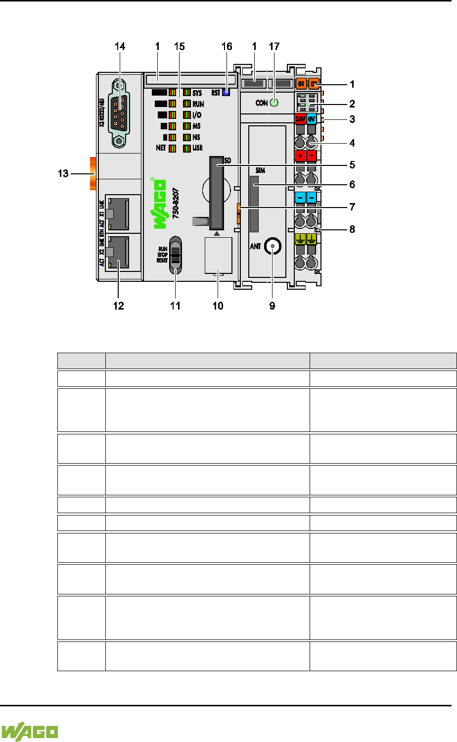
3.1 View
Figure 1: View of device
Table 4: Legend for Figure “View”
Item
Description
See section
1
Marking Options (Mini-WSB)
---
2 LED Indicators – Power Supply
“Indicating elements” >
“Indicating element power
supply”
3 Data contacts
“Connections” > “Data
contacts/Internal data bus”
4
CAGE CLAMP® Connections for Power
Supply
“Connections” > “CAGE
CLAMP® connections”
5
Slot for memory card
“Memory card slot”
6
Slot for SIM card
“SIM card slot”
7 Releasing strap
“Mounting” > “Inserting and
Removing Device”
8
Power contacts for power supply of
down-circuit I/O modules
“Connections” > “Power
contacts/ Field-side supply”
9 Mobile radio antenna connection
“Connections” > “Mobile
radio antenna
communication”
10 Service Interface (behind the flap)
“Connections” > “Service
interface”

28 Device Description WAGO-I/O-SYSTEM 750
750-8207 PFC200 CS 2ETH RS 3G
Manual
Draft version 1.2.1 from 2017-09-13, valid from FW Version 02.06.20(09)
11 Mode selector switch
“Operating elements” >
“Mode selector switch”
12 ETHERNET Connections
“Connections” > “Network
connections ETHERNET –
X1, X2”
13 Safe Locking Feature
“Mounting” > “Inserting and
Removing Device”
14 Serial interface
“Connections” >
“Communication port RS-
232/RS-485 – X3”
15 LED Indicators – System
“Indicating elements” >
“Indicating elements
Fieldbus/System”
16 Reset button (in hole)
“Operating elements” >
“Reset button”
17 LED indicators – Mobile radio network
status
"Indicating elements" >
"Indicating elements
Fieldbus/System"
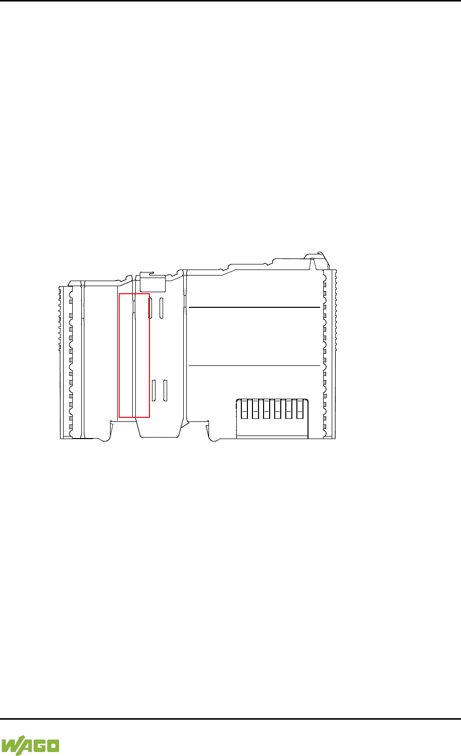
WAGO-I/O-SYSTEM 750 Device Description 29
750-8207 PFC200 CS 2ETH RS 3G
Manual
Draft version 1.2.1 from 2017-09-13, valid from FW Version 02.06.20(09)
3.2 Labeling
The front labeling includes:
- Device designation
- Name of the display elements, connections and control elements
- Serial number with hardware and firmware version
The side labeling includes:
- Manufacturer's identification
- Connector pin assignment
- Serial number
- Approval information
3.2.1 Manufacturing Number
The serial number indicates the delivery status directly after production.
Figure 2: Marking Area for Serial Numbers
There are two serial numbers in two rows in the side marking. They are left of the
release tab. The first 10 positions in the longer row of the serial numbers contain
version and date identifications.
Example structure of the rows: 0114010101…
01
14
01
01
01
(additional positions)
WW
YY
FW --
HW
FL
-
Calendar
week
Year
Firmware
version
Hardware
version
Firmware
loader
version
Internal information
The row order can vary depending on the production year, only the longer row is
relevant. The back part of this and the shorter row contain internal administration
information from the manufacturer.
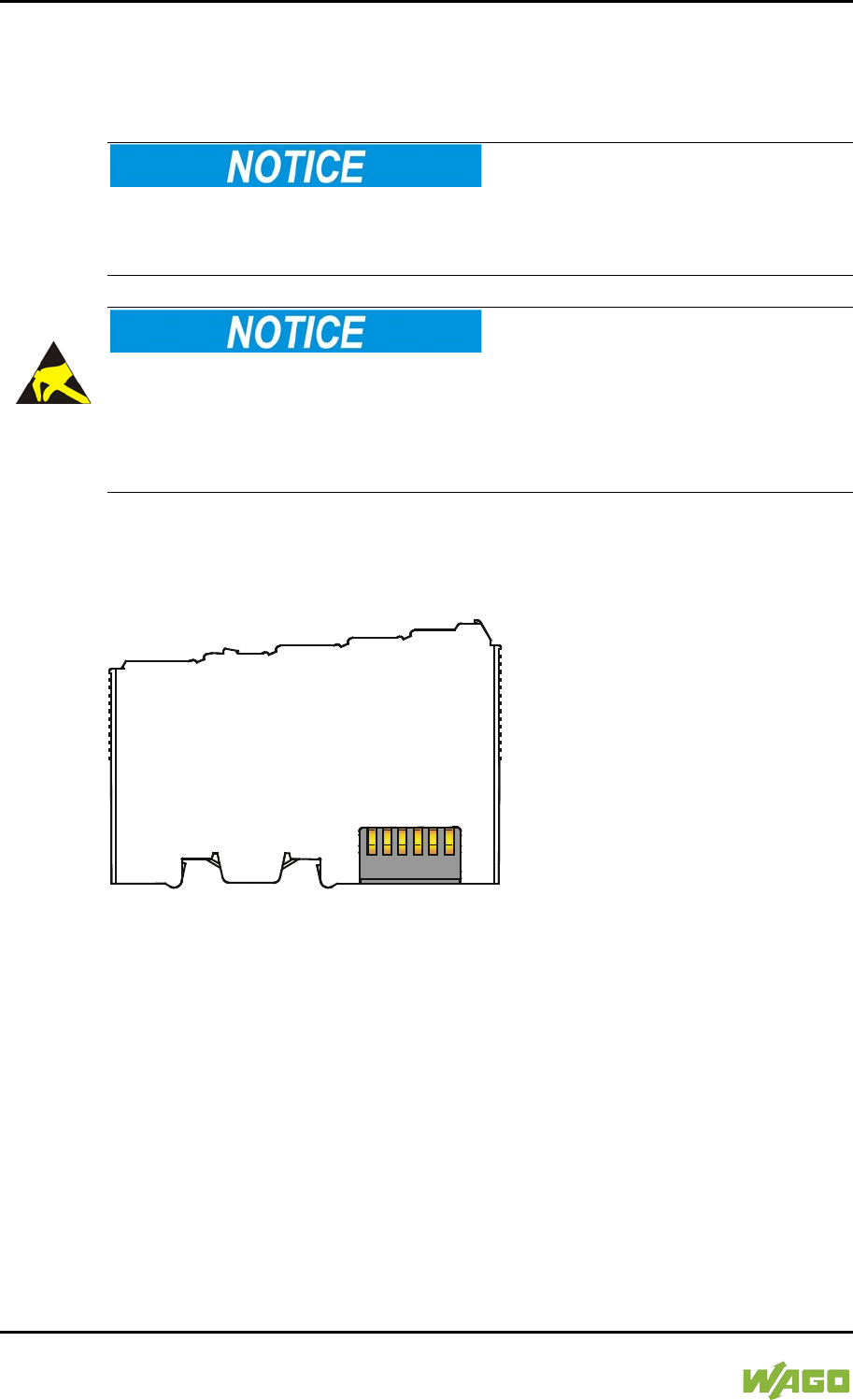
30 Device Description WAGO-I/O-SYSTEM 750
750-8207 PFC200 CS 2ETH RS 3G
Manual
Draft version 1.2.1 from 2017-09-13, valid from FW Version 02.06.20(09)
3.3 Connectors
3.3.1 Data Contacts/Internal Bus
Do not place the I/O modules on the gold spring contacts!
Do not place the I/O modules on the gold spring contacts in order to avoid soiling
or scratching!
Ensure that the environment is well grounded!
The devices are equipped with electronic components that may be destroyed by
electrostatic discharge. When handling the devices, ensure that the environment
(persons, workplace and packing) is well grounded. Avoid touching conductive
components, e.g. data contacts.
Communication between the controller and the I/O modules and system power
supply for the I/O modules is provided via the internal data bus, which consists of
6 data contacts designed as self-cleaning gold spring contacts.
Figure 3: Data Contacts
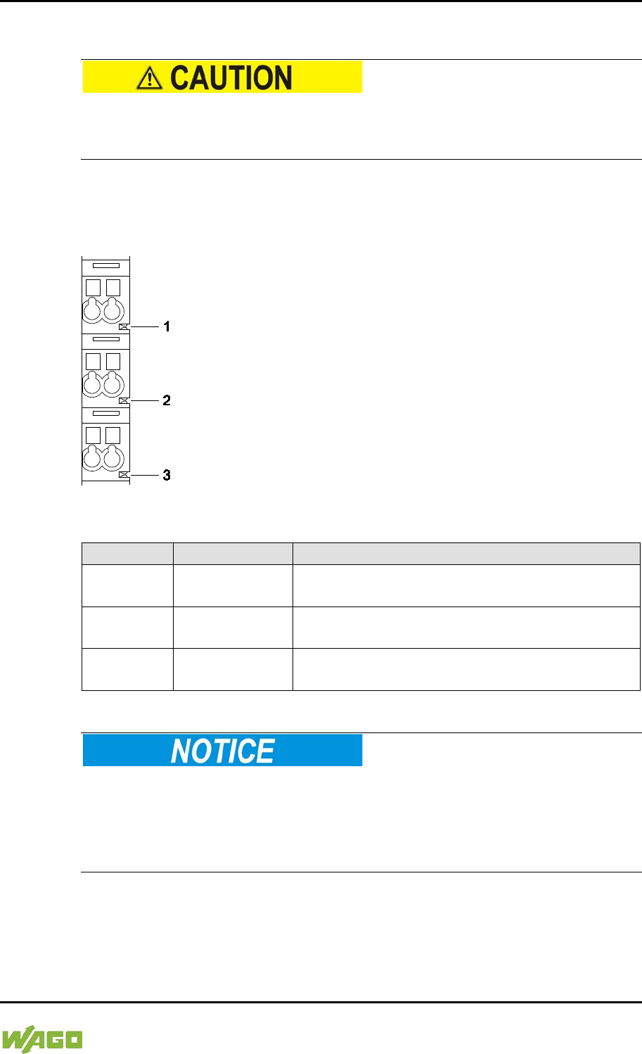
WAGO-I/O-SYSTEM 750 Device Description 31
750-8207 PFC200 CS 2ETH RS 3G
Manual
Draft version 1.2.1 from 2017-09-13, valid from FW Version 02.06.20(09)
3.3.2 Power Jumper Contacts/Field Supply
Risk of injury due to sharp-edged blade contacts!
The blade contacts are sharp-edged. Handle the I/O module carefully to prevent
injury.
The controller 750-8207is equipped with 3 self-cleaning power contacts for
transferring of the field-side power supply to down-circuit I/O modules. These
contacts are designed as spring contacts.
Figure 4: Power Jumper Contacts
Table 5: Legend for Figure “Power Jumper Contacts”
Contact
Type
Function
1 Spring contact
Potential transmission (U
V
)
for field supply
2 Spring contact
Potential transmission (0 V)
for field supply
3 Spring contact
Potential transmission (ground)
for field supply
Do not exceed maximum current via power jumper contacts!
The maximum current to flow through the power jumper contacts is 10 A.
Greater currents can damage the contacts.
When configuring your system, ensure that this current is not exceeded.
If exceeded, insert an additional supply module.
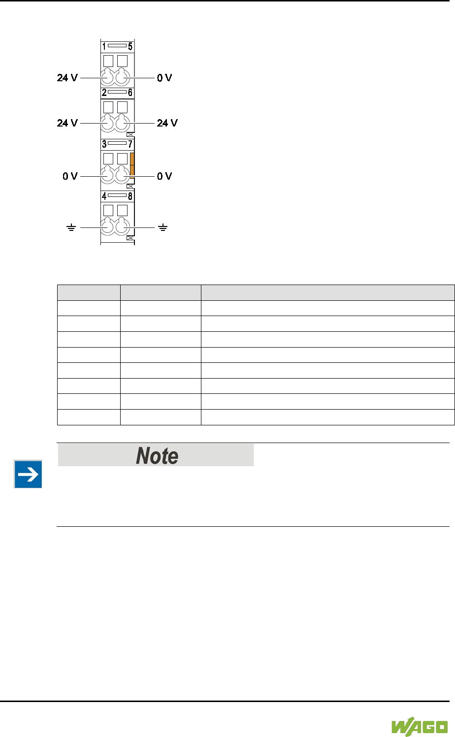
32 Device Description WAGO-I/O-SYSTEM 750
750-8207 PFC200 CS 2ETH RS 3G
Manual
Draft version 1.2.1 from 2017-09-13, valid from FW Version 02.06.20(09)
3.3.3 CAGE CLAMP® Connectors
Figure 5: CAGE CLAMP® connections
Table 6: Legend for figure “CAGE CLAMP® connections”
Contact
Description
Description
1
24 V
System power supply voltage +24 V
2
+
Field-side power supply voltage UV
3
-
Field-side power supply voltage 0 V
4
Ground
Field-side power supply voltage, ground
5
0 V
System power supply voltage 0 V
6
+
Field-side power supply voltage UV
7
-
Field-side power supply voltage 0 V
8
Ground
Field-side power supply voltage, ground
</dg_
Observe supplementary power supply regulations for use in shipbuilding!
Observe supplementary power supply regulations for shipbuilding and the supply
voltage in Section “Connect Devices” > … > “Supplementary Power Supply
Regulations”!
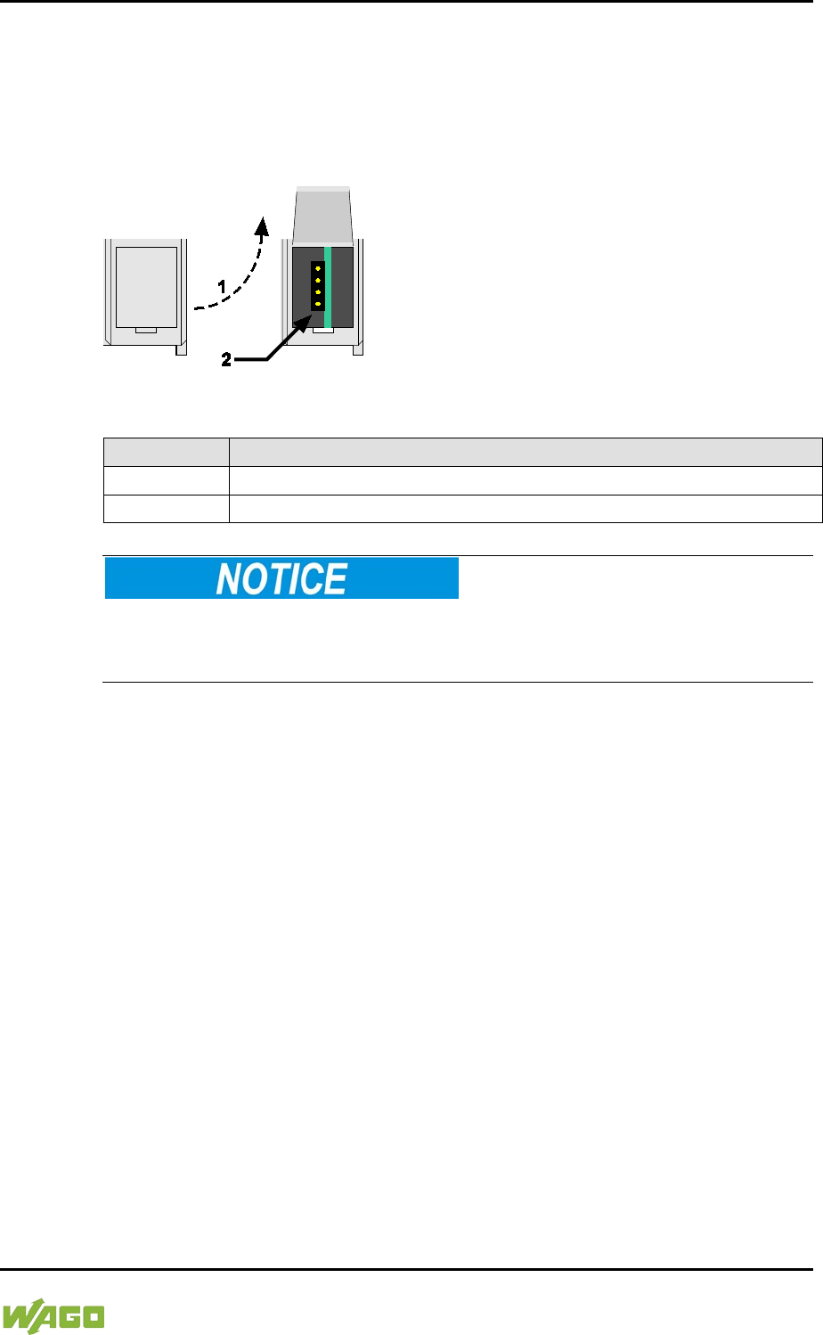
WAGO-I/O-SYSTEM 750 Device Description 33
750-8207 PFC200 CS 2ETH RS 3G
Manual
Draft version 1.2.1 from 2017-09-13, valid from FW Version 02.06.20(09)
3.3.4 Service Interface
The service interface is located behind the flap.
The Service interface is used for communication with WAGO-I/O-CHECK and
WAGO-ETHERNET-Settings and for firmware download.
Figure 6: Service Interface (Closed and Open Flap)
Table 7: Service Interface
Number
Description
1
Open flap
2
Service interface
Device must be de-energized!
To prevent damage to the device, unplug and plug in the communication cable
only when the device is de-energized!
The connection to the 4-pin header under the cover flap can be realized via the
communication cables with the item numbers750-920 and 750-923 or via the
WAGO radio adapter with the item number 750-921.
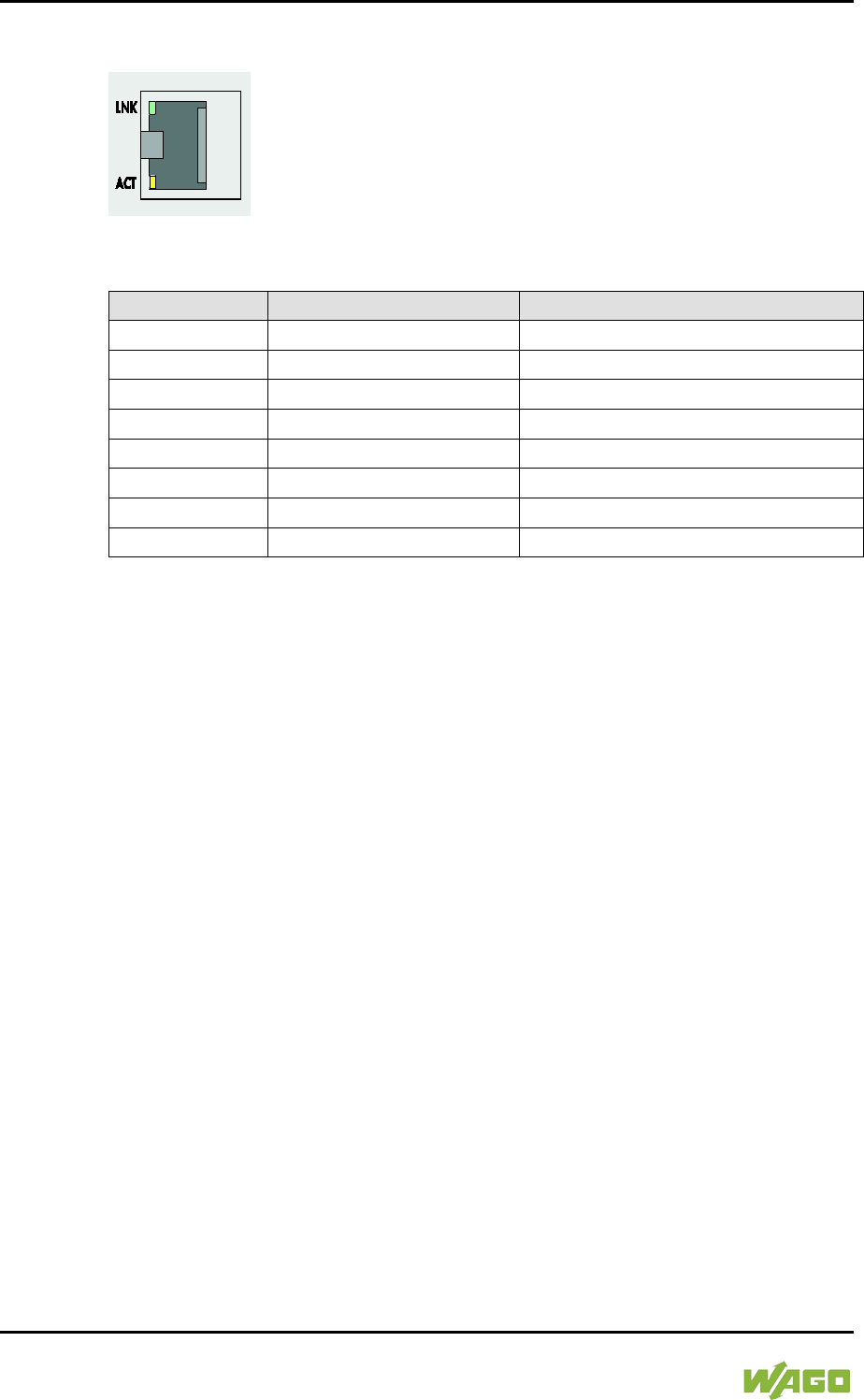
34 Device Description WAGO-I/O-SYSTEM 750
750-8207 PFC200 CS 2ETH RS 3G
Manual
Draft version 1.2.1 from 2017-09-13, valid from FW Version 02.06.20(09)
3.3.5 Network Connections – X1, X2
Figure 7: Network Connections – X1, X2
Table 8: Legend for Figure “Network Connections – X1, X2”
Contact
Signal
Description
1
TD +
Transmit Data +
2
TD −
Transmit Data −
3
RD +
Receive Data +
4
NC
Not assigned
5
NC
Not assigned
6
RD −
Receive Data −
7
NC
Not assigned
8
NC
Not assigned
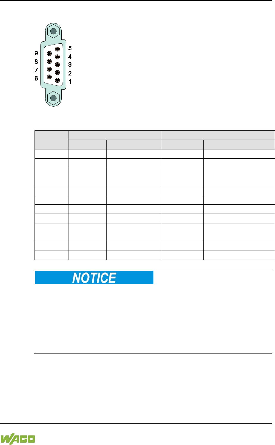
WAGO-I/O-SYSTEM 750 Device Description 35
750-8207 PFC200 CS 2ETH RS 3G
Manual
Draft version 1.2.1 from 2017-09-13, valid from FW Version 02.06.20(09)
Komm uni kati on sa ns c hl us s
3.3.6 RS-232/RS-485 – X3 Communication Connection
Figure 8: RS-232/RS-485 – X3 Communication Connection
Table 9: Legend for Figure “RS-232/RS-485 – X3 Communication Connection”
Contact
RS-232
RS-485
Signal
Description
Signal
Description
1
NC
Not assigned
NC
Not assigned
2
RxD
Receive Data
NC
Not assigned
3
TxD
Transmit Data
RxD/TxD-P
Receive/transmit data
+
4
NC
Not assigned
NC
Not assigned
5
FB_GND
Ground
FB_GND
Ground
6
NC
Not assigned
FB_5V
Power Supply
7
RTS
Request to send
NC
Not assigned
8
CTS
Clear to send
RxD/TxD-N
Receive/transmit data
−
9
NC
Not assigned
NC
Not assigned
Enclosure
Shield
Shielding
Shield
Shielding
Incorrect parameterization can damage the communication partners!
The voltage levels are −12 V and +12 V for RS-232, and −5 V and +5 V for
RS-485.
If the controller interfaces differ from those of the communication partners
(RS-232 <> RS-485 or RS-485 <> RS-232), this may damage the interface of the
communication partner.
Therefore, always ensure that the controller interface matches those of its
communication partners when configuring these items!
DC/DC converters and optocouplers in the fieldbus interface electrically isolate
the fieldbus system and the electronics.
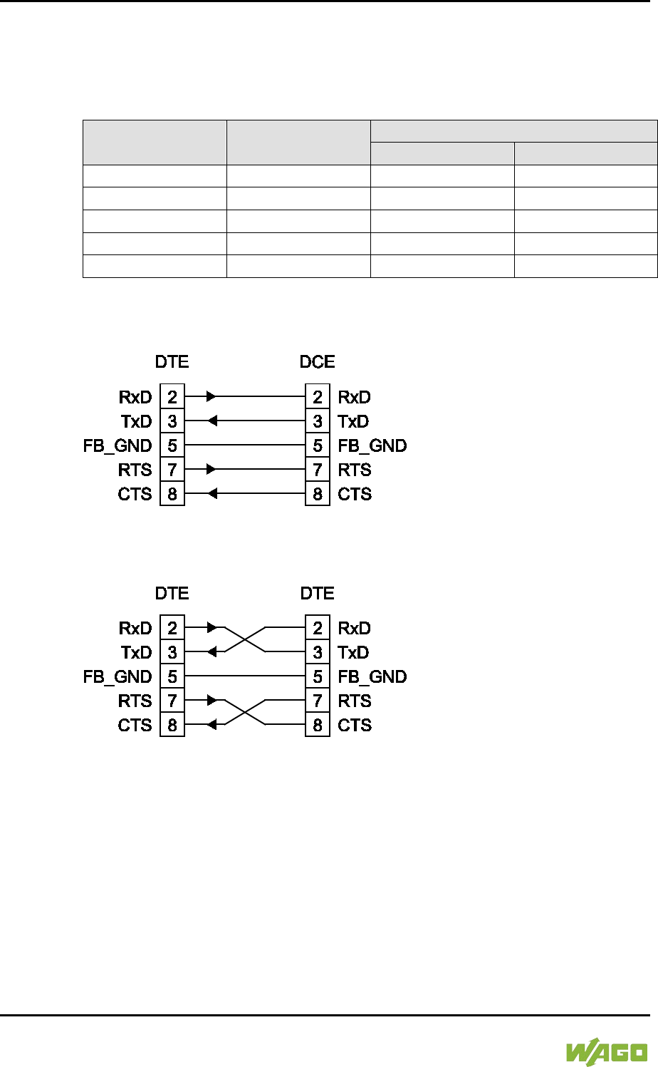
36 Device Description WAGO-I/O-SYSTEM 750
750-8207 PFC200 CS 2ETH RS 3G
Manual
Draft version 1.2.1 from 2017-09-13, valid from FW Version 02.06.20(09)
3.3.6.1 Operating as an RS-232 Interface
Depending on the device type DTE (e.g., PC) or DCE (e.g., PFC, modem), the
RS-232 signals have different data directions.
Table 10: Function of RS-232 Signals for DTE/DCE
Contact Signal
Data Direction
DTE
DCE
2
RxD
Input
Output
3
TxD
Output
Input
5
FB_GND
---
---
7
RTS
Output
Input
8
CTS
Input
Output
For a DTE-to-DCE connection, the signals are connected directly (1:1).
Figure 9: Termination with DTE-DCE Connection (1:1)
For a DTE-to-DTE connection, the signal connections are crossed.
Figure 10: Termination with DTE-DTE Connection (Cross-Over)
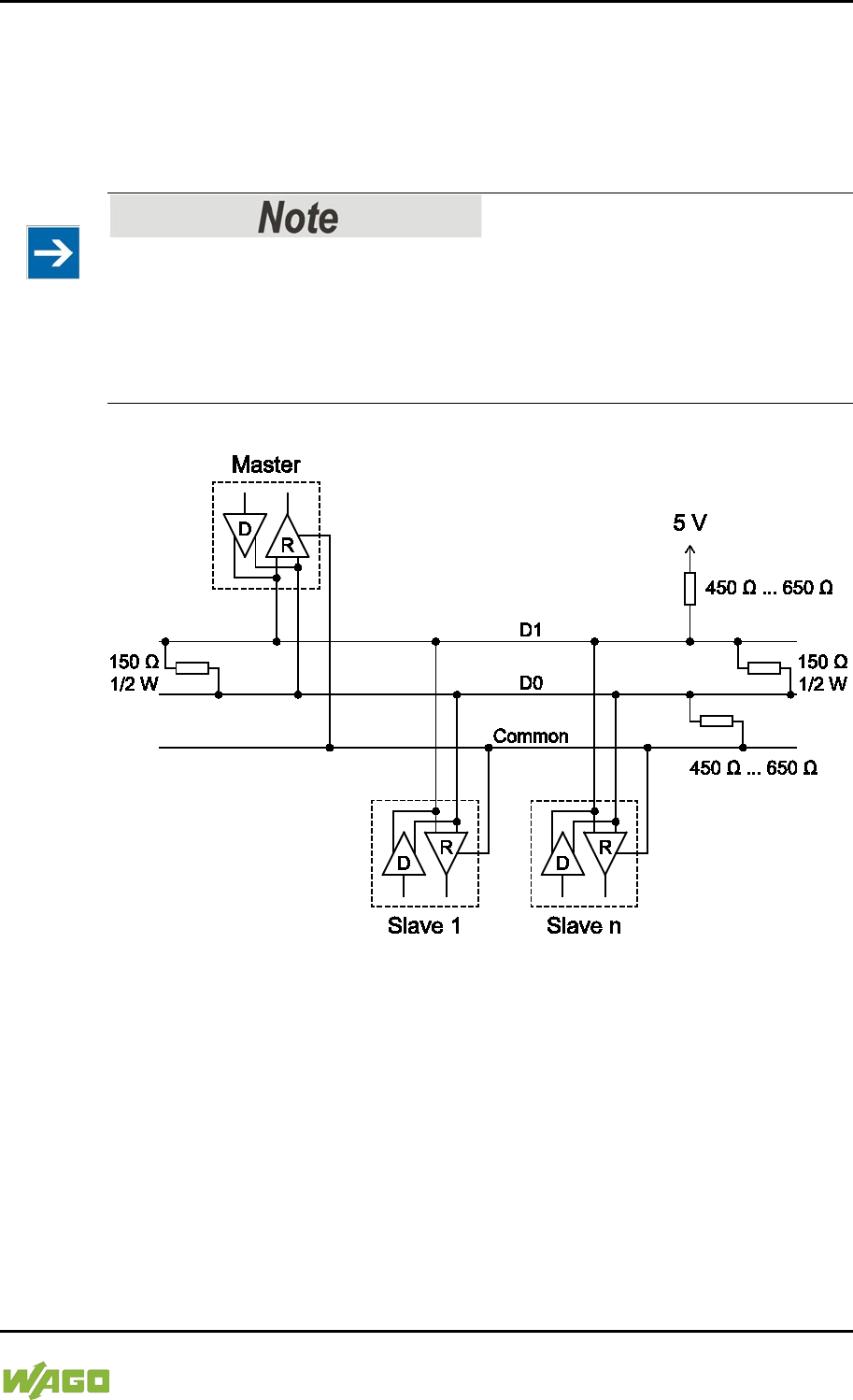
WAGO-I/O-SYSTEM 750 Device Description 37
750-8207 PFC200 CS 2ETH RS 3G
Manual
Draft version 1.2.1 from 2017-09-13, valid from FW Version 02.06.20(09)
3.3.6.2 Operating as an RS-485 Interface
To minimize reflection at the end of the line, the RS-485 line must be terminated
at both ends by a cable termination. If required, one pull-up or pull-down resistor
may be used. These resistors ensure a defined level on the bus when no
subscriber is active, i.e., when all subscribers are in “Tri-state”.
Attention — bus termination!
The RS-485 bus segment must be terminated at both ends!
No more than two terminations per bus segment may be used!
Terminations may not be used in stub and branch lines!
Operation without proper termination of the RS-485 network may result in
transmission errors.
Figure 11: RS-485 Bus Termination

38 Device Description WAGO-I/O-SYSTEM 750
750-8207 PFC200 CS 2ETH RS 3G
Manual
Draft version 1.2.1 from 2017-09-13, valid from FW Version 02.06.20(09)
3.3.7 Mobile Radio Antenna
The screw connector (SMA jack) for the mobile radio antenna is located at the
front of the housing.
Figure 12: Mobile Radio Antenna Connection

WAGO-I/O-SYSTEM 750 Device Description 39
750-8207 PFC200 CS 2ETH RS 3G
Manual
Draft version 1.2.1 from 2017-09-13, valid from FW Version 02.06.20(09)
3.4 Display Elements
3.4.1 Power Supply Indicating Elements
Figure 13: Power Supply Indicating Elements
Table 11: Legend for Figure “Power Supply Indicating Elements”
Description
Color
Description
A
Green/off
Status of system power supply voltage
B
Green/off
Status of field-side power supply voltage
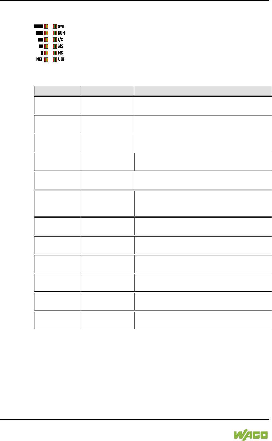
40 Device Description WAGO-I/O-SYSTEM 750
750-8207 PFC200 CS 2ETH RS 3G
Manual
Draft version 1.2.1 from 2017-09-13, valid from FW Version 02.06.20(09)
3.4.2 Fieldbus/System Indicating Elements
Figure 14: Indicating elements for fieldbus/system
Table 12: Legend for Figure “Fieldbus/System Indicating Elements”
Description
Color
Description
SYS
Red/Green/
Orange/Off
System status
RUN
Red/Green/
Orange/Off PLC program status
I/O
Red/Green/
Orange/Off
Internal data bus status
MS
Red/Green/
Orange/Off
Module status
NS
Red/Green/
Orange/Off
Without function
USR Red/Green/
Orange/Off
User LED, programmable using function
blocks from the WAGO libraries to control the
LEDs
▐██
Red/Green/
Orange/Off
Signal quality (S5)
██
Red/Green/
Orange/Off
Signal quality (S4)
▐█
Red/Green/
Orange/Off
Signal quality (S3)
█
Red/Green/
Orange/Off
Signal quality (S2)
▐
Red/Green/
Orange/Off Signal quality (S1)
NET
Red/Green/
Orange/Off Network status

WAGO-I/O-SYSTEM 750 Device Description 41
750-8207 PFC200 CS 2ETH RS 3G
Manual
Draft version 1.2.1 from 2017-09-13, valid from FW Version 02.06.20(09)
3.4.3 Memory Card Indicating Elements
Figure 15: Indicating Elements, Memory Card Slot
Table 13: Legend for Figure “Indicating Elements, Memory Card Slot”
Description
Color
Description
SD
Yellow/Off
Memory card status

42 Device Description WAGO-I/O-SYSTEM 750
750-8207 PFC200 CS 2ETH RS 3G
Manual
Draft version 1.2.1 from 2017-09-13, valid from FW Version 02.06.20(09)
3.4.4 Network Indicating Elements
Figure 16: Indicating Elements, RJ-45 Jacks
Table 14: Legend for Figure “Indicating Elements, RJ-45 Jacks”
Description
Color
Description
LNK
Green/Off
ETHERNET connection status
ACT
Yellow/Off
ETHERNET data exchange

WAGO-I/O-SYSTEM 750 Device Description 43
750-8207 PFC200 CS 2ETH RS 3G
Manual
Draft version 1.2.1 from 2017-09-13, valid from FW Version 02.06.20(09)
3.4.5 Mobile Radio Network Status Indicators
Figure 17: Mobile Radio Network Status Indicators
Table 15: Legend for the “Mobile Radio Network Status Indicators” Figure
Description
Color
Description
CON
Green/off
Mobile radio network status
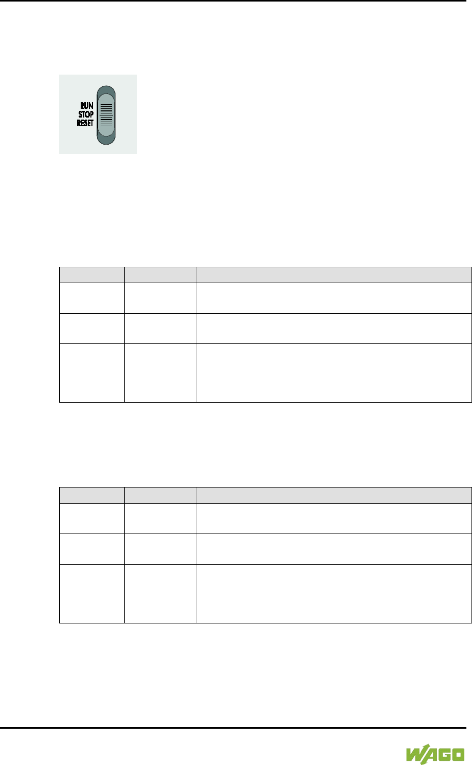
44 Device Description WAGO-I/O-SYSTEM 750
750-8207 PFC200 CS 2ETH RS 3G
Manual
Draft version 1.2.1 from 2017-09-13, valid from FW Version 02.06.20(09)
3.5 Operating Elements
3.5.1 Operating Mode Switch
Figure 18: Mode Selector Switch
The function of the mode selector switch depends on the activated runtime
system (CODESYS 2 or e!RUNTIME).
3.5.1.1 CODESYS 2 Runtime System
</dg_
Table 16: Mode Selector Switch
Item
Activation
Function
RUN Latching
Normal mode
CODESYS 2 application runs.
STOP Latching
Stop
CODESYS 2 application stopped.
RESET Spring-return
Reset warm start or
Reset cold start
(based on the duration of activation, see Section
“Starting” > “Initiating Reset Functions”)
</dg_
Other functions can also be initiated using the reset button.
3.5.1.2 e!RUNTIME Runtime System
</dg_
Table 17: Mode Selector Switch
Position
Actuation
Function
RUN Latching
Normal operation
e!RUNTIME applications running.
STOP Latching
Stop
All e!RUNTIME applications have stopped.
RESET Spring-return
Reset warm start or
Reset cold start
(depending on length of actuation, see Section
“Starting” > “Initiating Reset Functions”)
</dg_
Other functions can also be initiated using the reset button.

WAGO-I/O-SYSTEM 750 Device Description 45
750-8207 PFC200 CS 2ETH RS 3G
Manual
Draft version 1.2.1 from 2017-09-13, valid from FW Version 02.06.20(09)
3.5.2 Reset Button
Figure 19: Reset Button
The Reset button is installed behind drilling to prevent operating errors. It is a
shortstroke button with a low actuating force of 1.1 N … 2.1 N (110 gf … 210 gf).
The button can be actuated using a suitable object (e.g., pen).
You can initiate different functions using the Reset button depending on the
position of the mode selector:
- Temporarily set a fixed IP address
- Perform a software reset (restart)
- Restore factory setting (factory reset)
Please refer to the same sections in the back of this manual for information about
the functions.
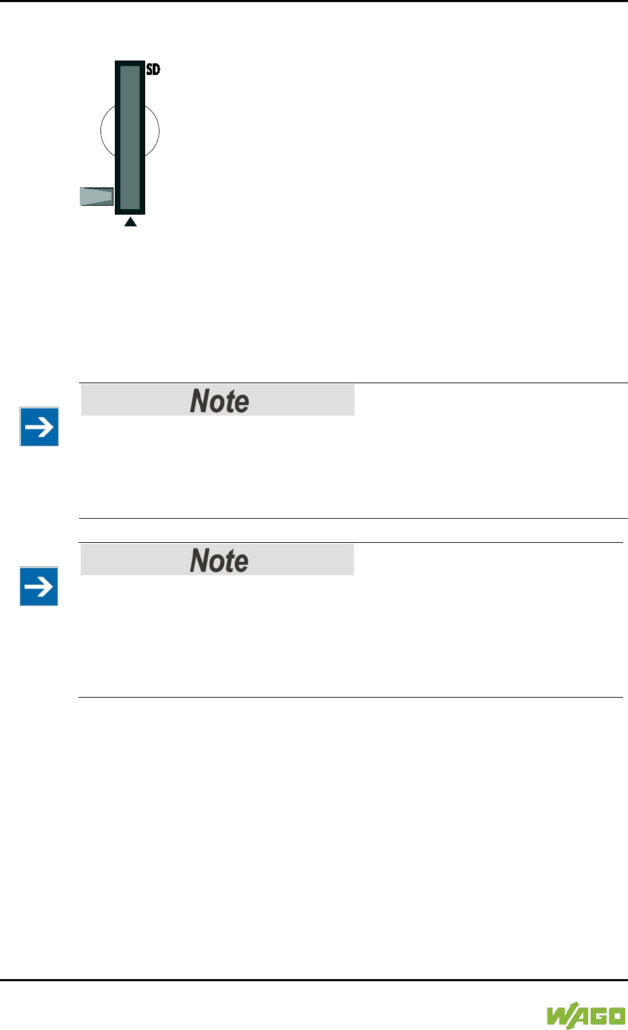
46 Device Description WAGO-I/O-SYSTEM 750
750-8207 PFC200 CS 2ETH RS 3G
Manual
Draft version 1.2.1 from 2017-09-13, valid from FW Version 02.06.20(09)
3.6 Slot for Memory Card
Figure 20: Slot for SD Memory Card
The slot for the SD memory card is located on the front of the housing. The
memory card is locked in the enclosure by a push/push mechanism. Inserting
and removing the memory card is described in the Section “Service” > “Inserting
and Removing the Memory Card.”
The memory card is protected by a cover flap. The cover cap is sealable.
Memory card is not included in the scope of delivery!
Note, the controller is delivered without memory card.
To use a memory card, you must order one separately. The controller can also
be operated without memory card expansion, the use of a memory card is
optional.
</dg_
Only use recommended memory cards!
Use only the SD memory card available from WAGO (item No. 758-879/000-
001) as it is suitable for industrial applications subjected to environmental
extremes and was developed for use in the controller.
Compatibility with other commercially available storage media cannot be
guaranteed.
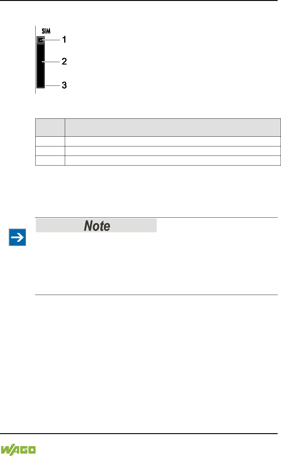
WAGO-I/O-SYSTEM 750 Device Description 47
750-8207 PFC200 CS 2ETH RS 3G
Manual
Draft version 1.2.1 from 2017-09-13, valid from FW Version 02.06.20(09)
3.7 SIM Card Slot
Figure 21: SIM Card Slot
Table 18: Legend for Figure “SIM Card Slot”
Positio
n
Description
1
Release button for SIM card slot
2
SIM card holder
3
SIM card slot
The SIM card slot is located on the front of the housing. The SIM card is locked in
the housing with a SIM card holder.
Inserting and removing the SIM card is described in the section “Service” >
“Inserting and Removing the SIM Card”!
SIM card not included!
Please note that an SIM card is required to use the mobile communications
function with the controller. The SIM card may be obtained from typical service
providers such as T-Mobile, VODAFONE or O2.
Select a suitable mobile communications tariff for your application, e.g., a flat-
rate deal with reduced data rates when the inclusive volume covered by the flat-
rate tariff is exceeded and/or a tariff with a texting package.
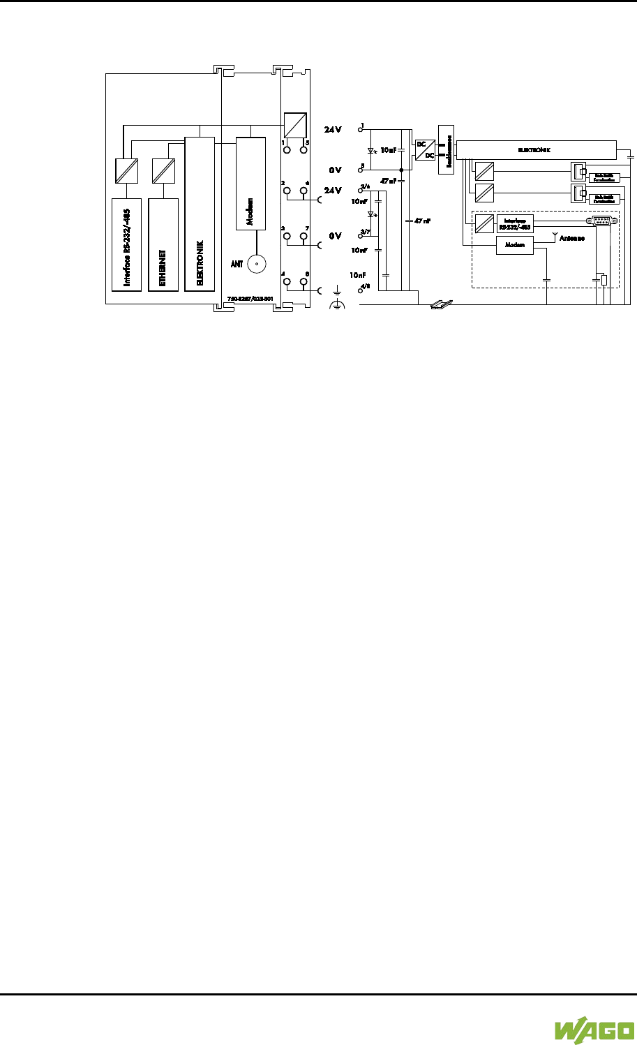
48 Device Description WAGO-I/O-SYSTEM 750
750-8207 PFC200 CS 2ETH RS 3G
Manual
Draft version 1.2.1 from 2017-09-13, valid from FW Version 02.06.20(09)
3.8 Schematic Diagram
Figure 22: Schematic diagram

WAGO-I/O-SYSTEM 750 Device Description 49
750-8207 PFC200 CS 2ETH RS 3G
Manual
Draft version 1.2.1 from 2017-09-13, valid from FW Version 02.06.20(09)
3.9 Technical Data
3.9.1 Device Data
Table 19: Technical Data − Device Data
Width
103 mm
Height (from upper edge of DIN 35 rail)
65 mm
Length
100 mm
Weight
288 g
</dg_
3.9.2 System Data
Table 20: Technical Data – System Data
CPU
Cortex A8, 600 MHz
Operating System
Real-time Linux® 3.18 (with RT
Preemption Patch)
Memory card slot
Push-push mechanism, sealable cover
lid
Type of memory card
SD and SDHC up to 32 Gbytes
(All guaranteed properties are valid only
in connection with the WAGO 758-
879/000-001 memory card.)
3.9.3 Power supply
Table 21: Technical Data – Power Supply
Power supply
24 VDC (-25 % … +30 %)
Max. input current (24 V)
550 mA
Power failure time acc. IEC 61131-2
Depending on external buffering
Total current for I/O modules (5V)
1700 mA
Isolation
500 V system/supply
Buffer for system power supply!
The system power supply must be buffered to bridge power outages. As the
power demand depends on the respective node configuration, buffering is not
implemented internally.
To achieve power outages of 1 ms to 10 ms according to IEC61131-2, determine
the buffering appropriate for your node configuration and structure it as an
external circuit.
</dg_

50 Device Description WAGO-I/O-SYSTEM 750
750-8207 PFC200 CS 2ETH RS 3G
Manual
Draft version 1.2.1 from 2017-09-13, valid from FW Version 02.06.20(09)
3.9.4 Clock
Table 22: Technical Data – Clock
Drift - system clock (25 °C)
20 ppm
Drift - RTC (25 °C)
3 ppm
Buffer time RTC (25 °C)
30 days
3.9.5 Programming
Table 23: Technical Data – Programming
Programming
CODESYS 2
WAGO-I/O-PRO V2.3
e!RUNTIME
e!COCKPIT
IEC 61131-3
IL, LD, FBD, ST, FC
CODESYS 2 memory configuration
Program memory (Flash)
16 MByte
Data memory (RAM)
64 MByte
Non-volatile memory (NVRAM,
Retain + Flags)
128 kByte
e!RUNTIME memory configuration
Program and data memory
60 MByte (dynamically distributed)
Non-volatile memory (NVRAM,
Retain + Flags)
128 kByte
Retain variables max.
CODESYS 2
10,000
e!RUNTIME
Not specified
3.9.6 Internal data bus
Table 24: Technical Data – Internal Data Bus
Number of I/O modules (per node)
64
with bus extension
250
Input and output process
image (max.)
CODESYS 2
1,000 words
e!RUNTIME
Not specified
WAGO-I/O-SYSTEM 750 Device Description 51
750-8207 PFC200 CS 2ETH RS 3G
Manual
Draft version 1.2.1 from 2017-09-13, valid from FW Version 02.06.20(09)
3.9.7 ETHERNET
Table 25: Technical Data – ETHERNET
ETHERNET
2 x RJ-45 (switched or separated mode)
Transmission medium
Twisted Pair S-UTP, 100 Ω, Cat 5,
100 m maximum cable length
Baud rate
10/100 Mbit/s; 10Base-T/100Base-TX
Protocols
DHCP, DNS, SNTP, FTP, FTPS (only
explicit connections), SNMP, HTTP,
HTTPS, SSH, MODBUS (TCP, UDP)
MODBUS input and
output process image,
max.
CODESYS 2
1,000 words,
also with MODBUS access to the flag
area (see Section "MODBUS" > … >
"Flag Area")
e!RUNTIME
32,000 words
No direct access from fieldbus to the process image for I/O modules!
Any data that is required from the I/O module process image must be explicitly
mapped in the CODESYS program to the data in the fieldbus process image and
vice versa! Direct access is not possible!
3.9.8 Serial interface
Table 26: Technical Data – Serial Interface
Interface
1 x serial interface per TIA/EIA 232 and
TIA/EIA 485 (switchable), 9-pole D-sub
female connector
Protocols
MODBUS RTU
3.9.9 Mobile Radio Modem
Table 27: Technical Data – Mobile Radio Modem
Technology
GSM / Edge / UMTS / HSPA+
SIM card type / slot
Mini SIM, push-push mechanism
Communication
Quad band
Communication types
SMS (bidirectional),
GPRS connection to the Internet
3.9.10 Connection Type
Table 28: Technical Data – Field Wiring
Wire connection
CAGE CLAMP®
Cross section
0.08 mm² … 2.5 mm², AWG 28 … 14
Stripped lengths
8 mm … 9 mm / 0.33 in

52 Device Description WAGO-I/O-SYSTEM 750
750-8207 PFC200 CS 2ETH RS 3G
Manual
Draft version 1.2.1 from 2017-09-13, valid from FW Version 02.06.20(09)
Table 29: Technical Data – Power Jumper Contacts
Power jumper contacts
Spring contact, self-cleaning
Table 30: Technical Data – Data Contacts
Data contacts
Slide contact, hard gold plated, self-
cleaning
3.9.11 Climatic Environmental Conditions
Table 31: Technical Data – Climatic Environmental Conditions
Operating temperature range
0 °C … 55 °C
Operating temperature range for
components with extended
temperature range (750-xxx/025-xxx)
−20 °C … +60 °C
Storage temperature range
−25 °C … +85 °C
Storage temperature range for
components with extended
temperature range (750-xxx/025-xxx)
−40 °C … +85 °C
Relative humidity
Max. 5 % … 95 % without condensation
Resistance to harmful substances
Acc. to IEC 60068-2-42 and
IEC 60068-2-43
Maximum pollutant concentration at
relative humidity < 75 %
SO
2
≤ 25 ppm
H
2
S ≤ 10 ppm
Special conditions
Ensure that additional measures for
components are taken, which are used in
an environment involving:
– dust, caustic vapors or gases
– ionizing radiation

WAGO-I/O-SYSTEM 750 Device Description 53
750-8207 PFC200 CS 2ETH RS 3G
Manual
Draft version 1.2.1 from 2017-09-13, valid from FW Version 02.06.20(09)
3.10 Approvals
More information about approvals.
Detailed references to the approvals are listed in the document “Overview
Approvals WAGO-I/O-SYSTEM 750”, which you can find via the internet under:
www.wago.com > SERVICES > DOWNLOADS > Additional documentation and
information on automation products > WAGO-I/O-SYSTEM 750 > System
Description.
The following approvals have been granted to the “PFC200 CS 2ETH RS 3G”
controller (750-8207):
Conformity Marking
FCC
Federal Communications Commission
This equipment has been tested and found to comply with the limits
for a Class A digital device, pursuant to Part 15 of the FCC Rules.
These limits are designed to provide reasonable protection against
harmful interference when the equipment is operated in a commercial
environment. This equipment generates, uses, and can radiate radio
frequency energy and, if not installed and used in accordance with the
instruction manual, may cause harmful interference to radio
communications. Operation of this equipment in a residential area is
likely to cause harmful interference in which case the user will be
required to correct the interference at his own expense.
Modifications not expressly approved by this company could void the
user´s authority to operate the equipment.
HF Exposition
This equipment complies with FCC and ISED radiation exposure
limits set forth for an uncontrolled environment. This equipment
should be installed and operated with a minimum distance of 20 cm
between the radiator and your body.
Cet équipement est conforme aux exigences des commissions FCC
et ISED relatives aux limitations de l'exposition à l'irradiation pour un
environnement non contrôlé. Cet équipement doit être installé et
utilisé en respectant une distance minimale de 20 cm entre le
radiateur et le corps humain.
3.11 Standards and Guidelines
The “PFC200 CS 2ETH RS 3G” controller (750-8207) fulfills the following EMC
standards:
EMC CE-Immunity to interference EN 61000-6-2

54 Device Description WAGO-I/O-SYSTEM 750
750-8207 PFC200 CS 2ETH RS 3G
Manual
Draft version 1.2.1 from 2017-09-13, valid from FW Version 02.06.20(09)
EMC CE-Emission of interference EN 61000-6-3

WAGO-I/O-SYSTEM 750 Function Description 55
750-8207 PFC200 CS 2ETH RS 3G
Manual
Draft version 1.2.1 from 2017-09-13, valid from FW Version 02.06.20(09)
4 Function Description
</dg_
4.1 Network
4.1.1 Interface Configuration
The ETHERNET X1 and X2 interfaces of the controller are connected with an
internal 3-port switch, in which the third port is connected to the CPU.
Interfaces X1 and X2 can either be operated in Switch mode or as separate
network interfaces. The switching can be performed during the runtime.
The Switch mode is activated by default and during initial startup. The
“Configuration mode” is set to “DHCP.”
For interface X1, a fixed IP address can be set (“Fix IP Address”). The setting is
carried out with the Reset button (see Section “Startup” > …> “Setting a Fixed IP
Address”).
Setting a fixed IP address has no effect on the mode previously set.
4.1.1.1 Operation in Switch Mode
For operation in Switch mode, the TCP/IP settings such as the IP address or
subnet mask apply to both X1 and X2.
When switching to Switch mode, the X1 settings are applied as a new common
configuration for X1 and X2.
The device is then no longer accessible via the IP address previously set for X2.
This must be taken into account for CODESYS applications that use X2 for
communication.
4.1.1.2 Operation with Separate Network Interfaces
When operating with separate network interfaces, both ETHERNET interfaces
can be configured and used separately.
Note that the two interfaces still have the same MAC address. Therefore, they
must not be operated in the same network segment.
When switching to operating with separate interfaces, interface X2 is initialized
with the setting values last valid for it. The connections on the X1 interface
persist.
When operating with separate interfaces and fixed IP address, the device can still
be accessed via the interface X2 via the regular IP address.
56 Function Description WAGO-I/O-SYSTEM 750
750-8207 PFC200 CS 2ETH RS 3G
Manual
Draft version 1.2.1 from 2017-09-13, valid from FW Version 02.06.20(09)
4.1.2 Network Security
4.1.2.1 Users and Passwords
Several groups of users are provided in the controller which can be used for
various services.
Default passwords are set for all users. We strongly recommend changing these
passwords on startup!
Change passwords
Default passwords are documented in these instructions and therefore do not
offer adequate protection! Change the passwords to meet your particular needs.
4.1.2.1.1 Services and Users
All password-protected services and their associated users are listed in the
following table.
Users
Service
WBM
Linux®
SNMP
admin
user
root
admin
user
Web Based Management
(WBM)
X X
Linux® console
X
X
X
Console Based Management
(CBM)
X X
CODESYS
X
Telnet
X
X
X
FTP
X
X
X
FTPS
X
X
X
SSH
X
X
X
SNMP
X
WAGO-I/O-SYSTEM 750 Function Description 57
750-8207 PFC200 CS 2ETH RS 3G
Manual
Draft version 1.2.1 from 2017-09-13, valid from FW Version 02.06.20(09)
4.1.2.1.2 WBM User Group
WBM has its own user administration system. The users in this system are
isolated from the other user groups in the system for security reasons.
Detailed information about this is given in the Section “WBM User
Administration”.
Table 32: WBM Users
Users
Permissions
Default Password
admin
All (administrator)
wago
user
Supported to a limited extent
user
guest
Display only
---
Change passwords
Default passwords are documented in these instructions and therefore do not
offer adequate protection! Change the passwords to meet your particular needs.
4.1.2.1.3 Linux® User Group
The Linux® users group include the actual users of the operating system, which is
likewise used by most services.
The passwords for these users must be configured through a terminal connection
via SSH/RS-232.
Table 33: Linux® Users
User
Special Feature
Home Directory
Default Password
root
Super user
/root
wago
admin
CODESYS user
/home/admin
wago
user
Normal user
/home/user
user
Change passwords
Default passwords are documented in these instructions and therefore do not
offer adequate protection! Change the passwords to meet your particular needs.
4.1.2.1.4 SNMP User Group
The SNMP service manages its own users. In its initial state, no users are stored
in the system.

58 Function Description WAGO-I/O-SYSTEM 750
750-8207 PFC200 CS 2ETH RS 3G
Manual
Draft version 1.2.1 from 2017-09-13, valid from FW Version 02.06.20(09)
4.1.2.2 Web Protocols for WBM Access
The HTTP and HTTPS web protocols can be used to access the WBM pages for
the controller. HTTPS is preferred because it uses the SSL/TLS protocol. The
SSL/TLS protocol ensures secure communication through encryption and
authentication
The default setting for the controller allows strong encryption, but uses only
simple authentication methods. As authentication for any secure communication
channel plays a central role, it is strongly recommended that you use secure
authentication. The security certificate saved on the controller is the basis for
authentication. The default location for the security certificate is:
/etc/lighttpd/https-cert.pem
As delivered, the controller uses a generic security certificate based on x509. To
allow secure authentication, you must replace the generic security certificate with
a security certificate specific for the individual device.
4.1.2.2.1 TLS Encryption
When an HTTPS connection is established, the Web browser and Webserver
negotiate what TLS version and what cryptographic method are to be used.
The “TLS Configuration” group of the WBM page “Security” can be used to switch
the cryptographic methods allowed for HTTPS and the TLS versions that can be
used.
The settings “Strong” and “Standard” are possible.
If “Strong” is set, the Webserver only allows TLS Version 1.2 and strong
algorithms.
Older software and older operating systems may not support TLS 1.2 and
encryption algorithms.
If “Standard” is set, TLS 1.0, TLS 1.1 and TLS 1.2 are allowed, as well as
cryptographic methods that are no longer considered secure.
BSI Technical Guidelines TR-02102
The rules for the “Strong” setting are based on technical guidelines TR-02102 of
the German Federal Office for Information Security.
You can find the guidelines on the Internet at: https://www.bsi.bund.de >
“Publications” > “Technical Guidelines.”

WAGO-I/O-SYSTEM 750 Function Description 59
750-8207 PFC200 CS 2ETH RS 3G
Manual
Draft version 1.2.1 from 2017-09-13, valid from FW Version 02.06.20(09)
BSI Guidelines on Migration to TLS 1.2
The German Federal Office for Information Security guidelines on migration to
TLS 1.2 contain “compatibility matrices” that show what software is comparable
with TLS 1.2.
You can find the guidelines on the Internet at: https://www.bsi.bund.de > “Topics”
> “Standards and Criteria” > “Minimum Standards“.

60 Function Description WAGO-I/O-SYSTEM 750
750-8207 PFC200 CS 2ETH RS 3G
Manual
Draft version 1.2.1 from 2017-09-13, valid from FW Version 02.06.20(09)
</dg_
4.1.3 Network Configuration
4.1.3.1 Host Name/Domain Name
Without a host name configuration, the controller is assigned a default name
which includes the last three values of the controller's MAC address, e.g.,
“PFCx00-A1A2A3.” This name is valid for as long as a host name was not
configured, or host name was not supplied to the controller via DHCP (for
configuration of the controller see Section “Startup” > “Configuring”). When the
host name is set, a host name supplied by a DHCP response is immediately
active and displaces the configured or default host name. If there are multiple
network interfaces with DHCP, the last received host name is valid. If only the
configured name is to be valid, the network administrator must adjust the
configuration of the active DHCP server so that no host names are transferred in
the DHCP response.
The default host name or the configured name is active again if the network
interfaces are set to static IP addresses or if a host name is not received via the
DHCP response.
A similar mechanism is used for a domain name as for the host name. The
difference is that a default domain name is not set. As long as a domain name is
not configured or supplied by DHCP, the domain name is empty.
4.1.3.2 Default Gateways
In the TCP/IP configuration, the controller allows the setting of two default
gateways. A network station transmits to a default gateway all network data
packets for systems outside of its local network. This gateway is responsible for
the appropriate routing of the data packets, so that they reach the target system.
The default gateways are assigned a so-called metric which specifies the time
delay, sometimes called the cost factor, with which a data packet can be routed
via the gateway. If multiple default gateways are configured, the operating
system transmits the data packets to the default gateway configured with the
lowest metric. If this gateway is not accessible, an attempt is made to access the
gateway with the next higher metric. The gateway is determined randomly if
multiple gateways have the same metric. If this gateway cannot transmit the data
packet, the data packet is sent simultaneously to all other gateways of the same
metric.
The metric of the configured default gateways can be set for the controller. The
default value for the metric is 20. Besides the directly configured gateways, other
gateways can be set via DHCP responses so that more than two gateways are
possible. All gateways transferred via DHCP are assigned a permanent metric of
10. The DHCP gateways are thus normally given priority on account of their low
metric.
The entries for Destination Address und Destination Mask make it possible to
define a complete route.

WAGO-I/O-SYSTEM 750 Function Description 61
750-8207 PFC200 CS 2ETH RS 3G
Manual
Draft version 1.2.1 from 2017-09-13, valid from FW Version 02.06.20(09)
There are two possibilities here:
1. Default Route
If the “default” value is entered in the Destination Address field, a default
route is defined. The Destination Mask field must then have the value
“0.0.0.0.”
2. Route
If an IP address or an address pool is entered in the Destination Address
field, all data is sent to the IP address or the address pool via the entered
gateway address.
The gateway metric here has an important function. This determines the
costs of the connection.
For example, if two identical address pools are defined (192.168.1.0/24)
[IP:192.168.1.1-192.168.1.254], one with a metric of 20 and the second
with 192.168.1.2 and a metric of 10, the gateway with the lowest metric is
used.
If the address 192.168.1.2 in the above example is no longer available,
e.g., due to failure, the alternative route is used automatically.

62 Function Description WAGO-I/O-SYSTEM 750
750-8207 PFC200 CS 2ETH RS 3G
Manual
Draft version 1.2.1 from 2017-09-13, valid from FW Version 02.06.20(09)
4.1.4 Network Services
4.1.4.1 DHCP Client
The controller can get network parameters from an external DHCP master via the
DHCP Client service.
The following parameters can be obtained:
- IP address
- SubNet mask
- Router/gateway
- Hostname
- Domain
- DNS server
- NTP server
For the IP address, SubNet mask and router/gateway parameters, the entries are
stored per ETHERNET port (X1, X2).
The Hostname and Domain parameters are stored according to the LIFO
principle (Last In First Out). The settings from the last DHCP offer received are
always used.
The DNS and NTP Server parameters are stored centrally for global use. All
transmitted parameters are saved.
4.1.4.2 DHCP Server
The controller provides the DHCP server service for the automatic configuration
of IP addresses of network stations on the same subnet.
Generally, only one DHCP server can be active on a subnet at one time.
The following can be set for the DHCP server:
- The service itself (active/not active)
- The range of dynamically assigned IP addresses
- The lease time of the dynamically assigned IP addresses
- A list with static assignments of IP addresses to MAC addresses
In “switched” mode, these settings are possible for both interfaces together and
in “separated” mode for each interface separately.

WAGO-I/O-SYSTEM 750 Function Description 63
750-8207 PFC200 CS 2ETH RS 3G
Manual
Draft version 1.2.1 from 2017-09-13, valid from FW Version 02.06.20(09)
The settings are made, for example, in the WBM via the “DHCP Configuration”
page.
The DHCP server also passes other parameters in addition to the IP address.
The following table shows the complete list.
Table 34: List of Parameters Transmitted via DHCP
Parameters
Explanation
IP address
An IP address from the range of permitted address; the
range can be configured in the WBM.
The DHCP server determines the IP address to be passed
to the requesting network subscriber (client) from the MAC
address of the network subscriber and the range of
addresses to be assigned. As long as the configured
address range does not change and no bottlenecks occur
when assigning IP addresses, the DHCP server
continuously reassigns the same IP addresses to
requesting network subscribers.
When a subscriber connects to the network, for whose
MAC address a fixed IP address has been configured in the
WBM, this address is passed to it. Such a fixed IP address
can also be outside the range of freely-assignable IP
addresses.
A hostname can also be specified instead of the MAC
address for identifying the requesting network subscriber.
Subnet mask
The subnet mask configured in the network settings of the
DHCP server for the local network concerned is passed.
The subnet mask and IP address determine the range of
valid IP addresses on the local network.
Broadcast address
IP address with which an IP packet can be sent to all
network subscribers on the subnet at the same time
Lease time
Determines the validity period of the DHCP parameters
passed to a network subscriber:
Per protocol, the network subscriber is required to request
the network settings again after half the period of validity.
The lease time is configured in the WBM.
Host name
The network name is passed to the network subscriber.
The network subscriber normally sends its own name with
its request for the IP address. It is then used by the DHCP
server in its response.
Name server
The DHCP server passes its own IP address as the DNS
name server to the network subscriber.
Default gateway
The DHCP server passes its own IP address as the default
gateway to the network subscriber.
The default gateway is required to communication with
subscribers outside the local network.
Not all parameters can be set in the WBM. If you want to set other values for the
existing parameters or want to pass other parameters via DHCP, the DHCP

64 Function Description WAGO-I/O-SYSTEM 750
750-8207 PFC200 CS 2ETH RS 3G
Manual
Draft version 1.2.1 from 2017-09-13, valid from FW Version 02.06.20(09)
server must be manually configured. For the controller, the DHCP server service
is handled by the program "dnsmasq".
From a Linux® command line, an editor must be used to change the file
“/etc/dnsmasq.d/dnsmasq_default.conf” to set the configuration.
4.1.4.3 DNS Server
The controller offers the DNS server service for the automatic assignment of
hostnames to IP addresses of network stations.
The DNS server takes over the names and IP addresses of local network stations
from the DHCP server. This DNS server routes requests for non-local names,
such as from the Internet, to higher-level DNS servers if configured and
accessible.
The following settings are possible for the DNS server:
- The service itself (enabled/disabled)
- Access type to the assignments
The requests are buffered in “Proxy” mode (throughput optimized).
In Relay mode the requests are routed directly to higher-level name
servers.
- A list with up to 15 static assignments of IP addresses to hostnames
If only the hostname is used, the configured or default domain is added to
the hostname automatically to ensure FQDN name resolution.
The settings are made, e.g., in the WBM, via the “Configuration of DNS Service”
page.
WAGO-I/O-SYSTEM 750 Function Description 65
750-8207 PFC200 CS 2ETH RS 3G
Manual
Draft version 1.2.1 from 2017-09-13, valid from FW Version 02.06.20(09)
4.2 Memory Card Function
</dg_
Only use recommended memory cards!
Use only the SD memory card available from WAGO (item No. 758-879/000-
001) as it is suitable for industrial applications subjected to environmental
extremes and was developed for use in the controller.
Compatibility with other commercially available storage media cannot be
guaranteed.
The memory card is optional and serves as an additional memory area in
addition to the internal memory or drive in the controller. The user program, user
data, source code of the project or device settings can be saved to the memory
card, and thus already existing project data and programs can be copied to one
or more controllers.
Deactivate write protection!
In order to be able to write data to the memory card, you must deactivate the
small push switch for the write protection setting. This switch is on one of the
long sides of the memory card.
If the memory card is inserted, this is incorporated under /media/sd in the
directory structure of the file system inside the controller. This means that the
memory card can be addressed like a removable medium on a PC.
The function of the memory card in normal operation and possible faults that may
occur when the memory card is used are described in the following sections for
different operating modes.
4.2.1 Formatting
Note the pre-formatting of the memory card!
Please note that memory cards ≤ 2 GB are often formatted with the “FAT16” file
system type and can generate up to 512 entries in the root directory. For over
512 entries create these in a subdirectory or format the memory card with
“FAT32” or “NTFS.”

66 Function Description WAGO-I/O-SYSTEM 750
750-8207 PFC200 CS 2ETH RS 3G
Manual
Draft version 1.2.1 from 2017-09-13, valid from FW Version 02.06.20(09)
Memory card access from CODESYS only possible with FAT16, FAT32 or
NTFS!
If the CODESYS user “admin” (see the section “Network” > “Network Security” >
“Users and Passwords” > “Services and Users“) is supposed to be able to access
files created on the memory card, the memory card must be formatted with
FAT16, FAT32 or NTFS.
If the Linux® file system formats EXT2 or EXT3 are used, “root” rights are
required for data access. Therefore, access via CODESYS is not possible.

WAGO-I/O-SYSTEM 750 Function Description 67
750-8207 PFC200 CS 2ETH RS 3G
Manual
Draft version 1.2.1 from 2017-09-13, valid from FW Version 02.06.20(09)
4.2.2 Data Backup
The controller has a backup function and a restore function.
The necessary settings can be made and the functions can be executed via the
WBM pages or via the CBM “Backup” and “Restore” menus.
The storage medium (internal memory or SD card) and, if applicable, the storage
location on the network can be set.
The data to be backed up and restored can also be selected:
• the CODESYS project (“PLC Runtime project,” boot project)
• the device settings (“Settings”)
• the controller operating system (“System”)
• all of the above (“All,” only visible if not saved on the network)
Note the firmware version!
Restoring the controller operating system (“System” selection) is only permissible
and possible if the firmware versions at the backup and restore times are
identical.
If necessary, skip restoring the controller operating system, or match the
firmware version of the controller to the firmware version of the backup time
beforehand.
4.2.2.1 Backup Function
The backup function enables the data of the internal memory and device settings
to be saved on the memory card during operation.
The backup function can be called via the WBM page “Firmware Backup” or the
CBM menu “Firmware Backup.”
The network or the inserted memory card can be selected as the target medium.
The files of the internal drive are stored on the target medium in the directory
media/sd/copy and in the corresponding subdirectories.
The information that is not present as files on the controller is stored in XML
format in the directory media/sd/settings/.
If the memory card is selected as the target medium, the LED above the memory
card slot flashes yellow/orange during the save operation.
The device settings and files of the internal drive are then saved on the target
medium.
68 Function Description WAGO-I/O-SYSTEM 750
750-8207 PFC200 CS 2ETH RS 3G
Manual
Draft version 1.2.1 from 2017-09-13, valid from FW Version 02.06.20(09)
The controller has an automatic update function. If this function is activated on a
memory card before the data backup and a controller is booted from this memory
card, this data is restored automatically on the internal memory of the controller.
Only one package may be copied to the network!
If you have specified “Network” as the storage location, only one package may
be selected for each storing process.
No backup of the memory card!
Backup from the memory card to the internal flash memory is not possible.
Account for backup time
Generation of backup files can take several minutes. Stop the CODESYS
program before you start the backup procedure to help shorten the time required.
4.2.2.2 Restore Function
The restore function is used to load the data and device settings from the
memory card to the internal memory during operation.
The restore function can be called via the WBM page “Firmware Restore” or the
CBM menu “Firmware Restore.”
The network or, if it is inserted, the memory card can be selected as the source
medium.
If the memory card is selected as the source medium, the LED above the
memory card slot flashes yellow/orange during the load operation.
When loading the data, the files are copied from the directory media/sd/copy/ of
the source medium to the appropriate directories on the internal memory.
The device has an active and an inactive root partition. The system backup is
stored on the inactive partition. Startup is then performed from the newly written
partition. If the startup process can be completed, the new partition is switched to
active. Otherwise, booting is performed again from the old active partition during
the next boot process.
The boot project is loaded automatically and the settings automatically activated
after a restart. The “Boot project location” setting on the “General PLC Runtime
Configuration Web” page of the WBM determines whether the boot project of the
internal drive or the memory card is loaded.
WAGO-I/O-SYSTEM 750 Function Description 69
750-8207 PFC200 CS 2ETH RS 3G
Manual
Draft version 1.2.1 from 2017-09-13, valid from FW Version 02.06.20(09)
File size must not exceed the size of the internal drive!
Note that the amount of data in the media/sd/copy/ directory must not exceed the
total size of the internal drive.
Restoration only possible from internal memory!
If the device was booted from the memory card, the firmware cannot be restored.
Reset by restore
A reset is performed when the system or settings are restored by CODESYS!
Connection loss through restore
If the restore changes the parameters of the ETHERNET connection, the WBM
may then no longer be able to open a connection to the device. You must call the
WBM again by entering the correct IP address of the device in the address line.
70 Function Description WAGO-I/O-SYSTEM 750
750-8207 PFC200 CS 2ETH RS 3G
Manual
Draft version 1.2.1 from 2017-09-13, valid from FW Version 02.06.20(09)
4.2.3 Inserting a Memory Card during Operation
The fieldbus nodes and the PLC program are running.
Insert a memory card during ongoing operation.
During normal operation, the memory card is incorporated into the file system of
the controller as a drive.
No automatic copy procedures are triggered.
The LED above the memory card flashes yellow/orange during the access.
The memory card is then ready for operation and available under /media/sd.
4.2.4 Removing the Memory Card during Operation
The fieldbus node and the PLC program are in operation and the memory card is
plugged in.
Remove the memory card during ongoing operation.
Data can be lost during writing!
Note that if you pull the memory card out during a write procedure, data will be
lost.
The LED above the memory card flashes yellow/orange during the attempted
access.
The controller then works without a memory card.

WAGO-I/O-SYSTEM 750 Function Description 71
750-8207 PFC200 CS 2ETH RS 3G
Manual
Draft version 1.2.1 from 2017-09-13, valid from FW Version 02.06.20(09)
4.2.5 Setting the Home Directory for the Runtime System
The home directory for the runtime system is located in the controller's internal
memory by default. An existing boot project may be saved in the home directory.
You can use the WBM to move the home directory for the runtime system to the
memory card, e.g., to make more memory available for a large boot project or
other files.
Some conditions must be met before moving the directory.
• A running IEC-61131 application must be stopped and the device restored
to its initial state using the “Reset” function. Any boot project is deleted.
• When moving the home directory to the memory card, insert a memory
card formatted to support file system. Only the first partition of a memory
card can be accessed at /media/sd and can be used as the home directory.
Only when the two conditions are met can the “Home directory on memory card
enabled” checkbox be selected from the WBM on the “PLC Runtime” page.
Press the [Submit] button to apply the settings, which take effect after the next
restart.
No files are applied from the old to the new home directory.
After moving the directory, a project must be loaded and a boot project created.
It should be noted that the memory card may not be removed under any
circumstances as long as the home directory is there. If an application is running,
system safety can be endangered by an uncontrolled controller crash.
Switching the home directory has no effect if the controller was botted from a
memory card. The configuration state is saved, but only takes effect if the content
of the memory card is copied to the internal memory.
72 Mounting WAGO-I/O-SYSTEM 750
750-8207 PFC200 CS 2ETH RS 3G
Manual
Draft version 1.2.1 from 2017-09-13, valid from FW Version 02.06.20(09)
5 Mounting
5.1 Installation Position
Along with horizontal and vertical installation, all other installation positions are
allowed.
Use an end stop in the case of vertical mounting!
In the case of vertical assembly, an end stop has to be mounted as an additional
safeguard against slipping.
WAGO order no. 249-116 End stop for DIN 35 rail, 6 mm wide
WAGO order no. 249-117 End stop for DIN 35 rail, 10 mm wide
5.2 Overall Configuration
The maximum total length of a fieldbus node without fieldbus coupler/controller is
780 mm including end module. The width of the end module is 12 mm. When
assembled, the I/O modules have a maximum length of 768 mm.
Examples:
• 64 I/O modules with a 12 mm width can be connected to a fieldbus
coupler/controller.
• 32 I/O modules with a 24 mm width can be connected to a fieldbus
coupler/controller.
Exception:
The number of connected I/O modules also depends on the type of fieldbus
coupler/controller is used. For example, the maximum number of stackable I/O
modules on one PROFIBUS DP/V1 fieldbus coupler/controller is 63 with no
passive I/O modules and end module.
Observe maximum total length of a fieldbus node!
The maximum total length of a fieldbus node without fieldbus coupler/controller
and without using a 750-628 I/O Module (coupler module for internal data bus
extension) may not exceed 780 mm.
Also note the limitations of individual fieldbus couplers/controllers.

WAGO-I/O-SYSTEM 750 Mounting 73
750-8207 PFC200 CS 2ETH RS 3G
Manual
Draft version 1.2.1 from 2017-09-13, valid from FW Version 02.06.20(09)
Increase the total length using a coupler module for internal data bus
extension!
You can increase the total length of a fieldbus node by using a 750-628 I/O
Module (coupler module for internal data bus extension). For such a
configuration, attach a 750-627 I/O Module (end module for internal data bus
extension) after the last I/O module of a module assembly. Use an RJ-45 patch
cable to connect the I/O module to the coupler module for internal data bus
extension of another module block.
This allows you to segment a fieldbus node into a maximum of 11 blocks with
maximum of 10 I/O modules for internal data bus extension.
The maximum cable length between two blocks is five meters.
More information is available in the manuals for the 750-627 and 750-628 I/O
Modules.

74 Mounting WAGO-I/O-SYSTEM 750
750-8207 PFC200 CS 2ETH RS 3G
Manual
Draft version 1.2.1 from 2017-09-13, valid from FW Version 02.06.20(09)
5.3 Mounting onto Carrier Rail
5.3.1 Carrier Rail Properties
All system components can be snapped directly onto a carrier rail in accordance
with the European standard EN 50022 (DIN 35).
Do not use any third-party carrier rails without approval by WAGO!
WAGO Kontakttechnik GmbH & Co. KG supplies standardized carrier rails that
are optimal for use with the I/O system. If other carrier rails are used, then a
technical inspection and approval of the rail by WAGO Kontakttechnik GmbH &
Co. KG should take place.
Carrier rails have different mechanical and electrical properties. For the optimal
system setup on a carrier rail, certain guidelines must be observed:
• The material must be non-corrosive.
• Most components have a contact to the carrier rail to ground electro-
magnetic disturbances. In order to avoid corrosion, this tin-plated carrier rail
contact must not form a galvanic cell with the material of the carrier rail
which generates a differential voltage above 0.5 V (saline solution of 0.3 %
at 20°C).
• The carrier rail must optimally support the EMC measures integrated into
the system and the shielding of the I/O module connections.
• A sufficiently stable carrier rail should be selected and, if necessary,
several mounting points (every 20 cm) should be used in order to prevent
bending and twisting (torsion).
• The geometry of the carrier rail must not be altered in order to secure the
safe hold of the components. In particular, when shortening or mounting the
carrier rail, it must not be crushed or bent.
• The base of the I/O components extends into the profile of the carrier rail.
For carrier rails with a height of 7.5 mm, mounting points are to be riveted
under the node in the carrier rail (slotted head captive screws or blind
rivets).
• The metal springs on the bottom of the housing must have low-impedance
contact with the DIN rail (wide contact surface is possible).
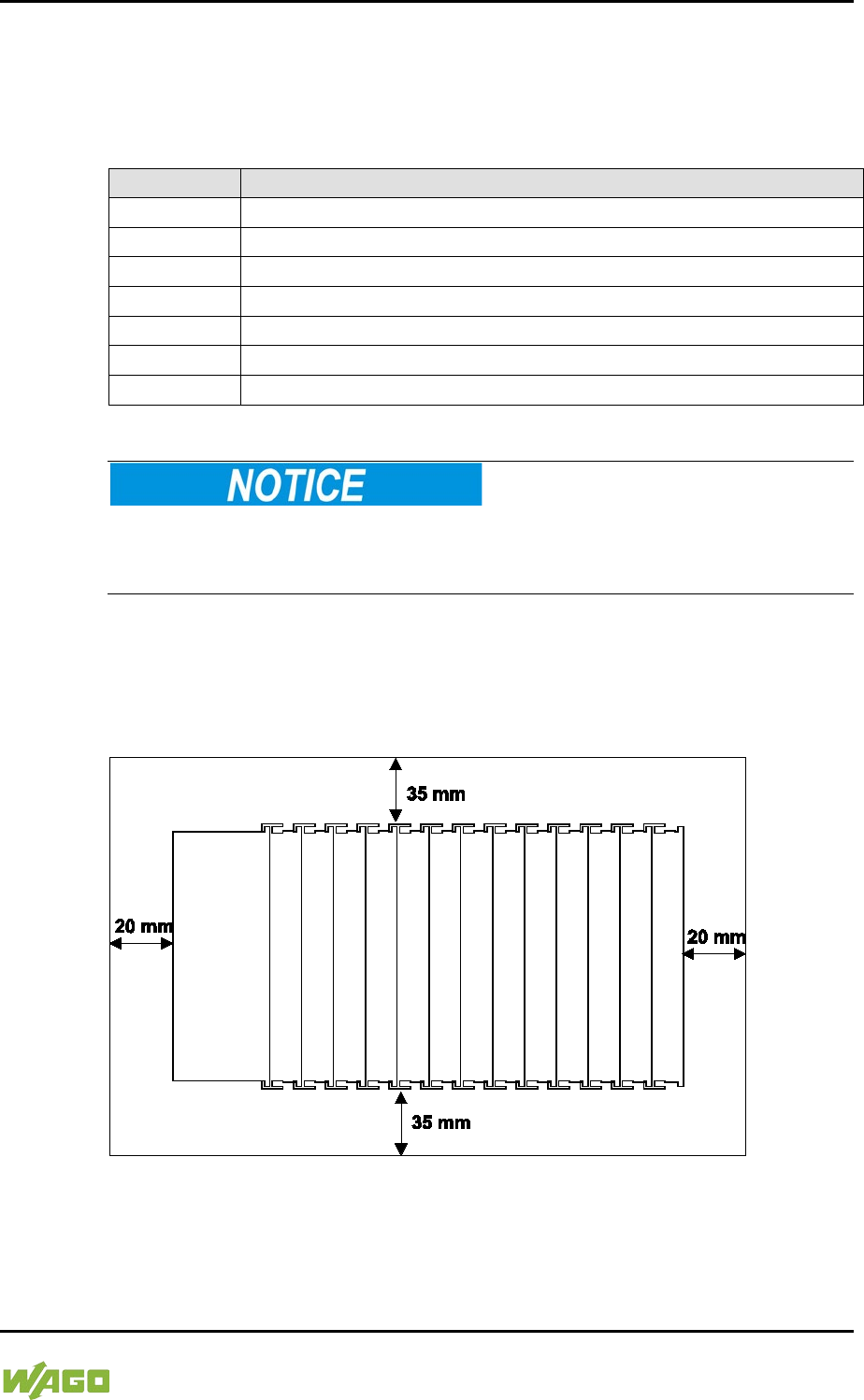
WAGO-I/O-SYSTEM 750 Mounting 75
750-8207 PFC200 CS 2ETH RS 3G
Manual
Draft version 1.2.1 from 2017-09-13, valid from FW Version 02.06.20(09)
5.3.2 WAGO DIN Rails
WAGO carrier rails meet the electrical and mechanical requirements shown in the
table below.
Table 35: WAGO DIN Rails
Item No.
Description
210-112
35 × 7.5; 1 mm; steel; bluish, tinned, chromed; slotted
210-113
35 × 7.5; 1 mm; steel; bluish, tinned, chromed; unslotted
210-197
35 × 15; 1.5 mm; steel; bluish, tinned, chromed; slotted
210-114
35 × 15; 1.5 mm; steel; bluish, tinned, chromed; unslotted
210-118
35 × 15; 2.3 mm; steel; bluish, tinned, chromed; unslotted
210-198
35 × 15; 2.3 mm; copper; unslotted
210-196
35 × 8.2; 1.6 mm; aluminum; unslotted
Observe the mounting distance of the DIN rail when the load is increased!
With increased vibration and shock load, mount the DIN rail at a mounting
distance of max. 60 mm.
5.4 Spacing
The spacing between adjacent components, cable conduits, casing and frame
sides must be maintained for the complete fieldbus node.
Figure 23: Spacing
The spacing creates room for heat transfer, installation or wiring. The spacing to
cable conduits also prevents conducted electromagnetic interferences from
influencing the operation.
76 Mounting WAGO-I/O-SYSTEM 750
750-8207 PFC200 CS 2ETH RS 3G
Manual
Draft version 1.2.1 from 2017-09-13, valid from FW Version 02.06.20(09)
5.5 Mounting Sequence
Fieldbus couplers/controllers and I/O modules of the WAGO-I/O-SYSTEM 750
are snapped directly on a carrier rail in accordance with the European standard
EN 50022 (DIN 35).
The reliable positioning and connection is made using a tongue and groove
system. Due to the automatic locking, the individual devices are securely seated
on the rail after installation.
Starting with the fieldbus coupler/controller, the I/O modules are mounted
adjacent to each other according to the project design. Errors in the design of the
node in terms of the potential groups (connection via the power contacts) are
recognized, as the I/O modules with power contacts (blade contacts) cannot be
linked to I/O modules with fewer power contacts.
Risk of injury due to sharp-edged blade contacts!
The blade contacts are sharp-edged. Handle the I/O module carefully to prevent
injury.
Insert I/O modules only from the proper direction!
All I/O modules feature grooves for power jumper contacts on the right side. For
some I/O modules, the grooves are closed on the top. Therefore, I/O modules
featuring a power jumper contact on the left side cannot be snapped from the
top. This mechanical coding helps to avoid configuration errors, which may
destroy the I/O modules. Therefore, insert I/O modules only from the right and
from the top.
Don't forget the bus end module!
Always plug a bus end module (750-600) onto the end of the fieldbus node! You
must always use a bus end module at all fieldbus nodes with WAGO-I/O-
SYSTEM 750 fieldbus couplers/controllers to guarantee proper data transfer.
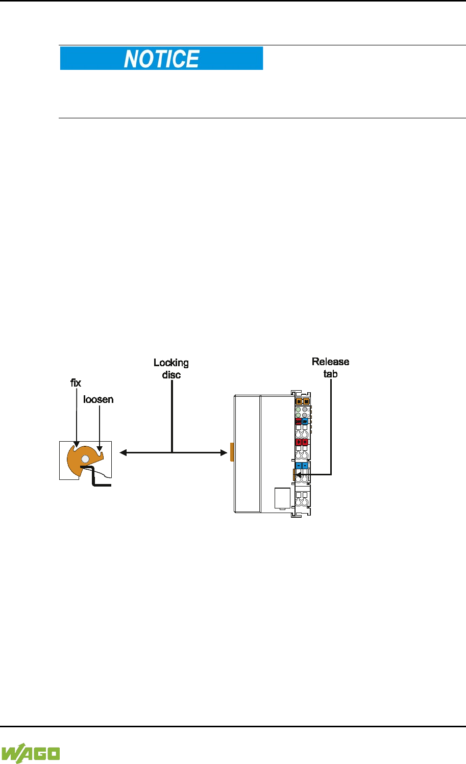
WAGO-I/O-SYSTEM 750 Mounting 77
750-8207 PFC200 CS 2ETH RS 3G
Manual
Draft version 1.2.1 from 2017-09-13, valid from FW Version 02.06.20(09)
5.6 Inserting Devices
Perform work on devices only if they are de-energized!
Working on energized devices can damage them. Therefore, turn off the power
supply before working on the devices.
5.6.1 Inserting the Controller
1. When replacing the controller for an already available controller, position
the new controller so that the tongue and groove joints to the subsequent
I/O module are engaged.
2. Snap the controller onto the carrier rail.
3. Use a screwdriver blade to turn the locking disc until the nose of the locking
disc engages behind the carrier rail (see the following figure). This prevents
the controller from canting on the carrier rail.
With the controller snapped in place, the electrical connections for the data
contacts and power contacts (if any) to the possible subsequent I/O module are
established.
Figure 24: Release Tab of Controller

78 Mounting WAGO-I/O-SYSTEM 750
750-8207 PFC200 CS 2ETH RS 3G
Manual
Draft version 1.2.1 from 2017-09-13, valid from FW Version 02.06.20(09)
5.6.2 Inserting the I/O Module
1. Position the I/O module so that the tongue and groove joints to the fieldbus
coupler/controller or to the previous or possibly subsequent I/O module are
engaged.
Figure 25: Insert I/O Module (Example)
2. Press the I/O module into the assembly until the I/O module snaps into the
carrier rail.
Figure 26: Snap the I/O Module into Place (Example)
With the I/O module snapped in place, the electrical connections for the data
contacts and power jumper contacts (if any) to the fieldbus coupler/controller or
to the previous or possibly subsequent I/O module are established.
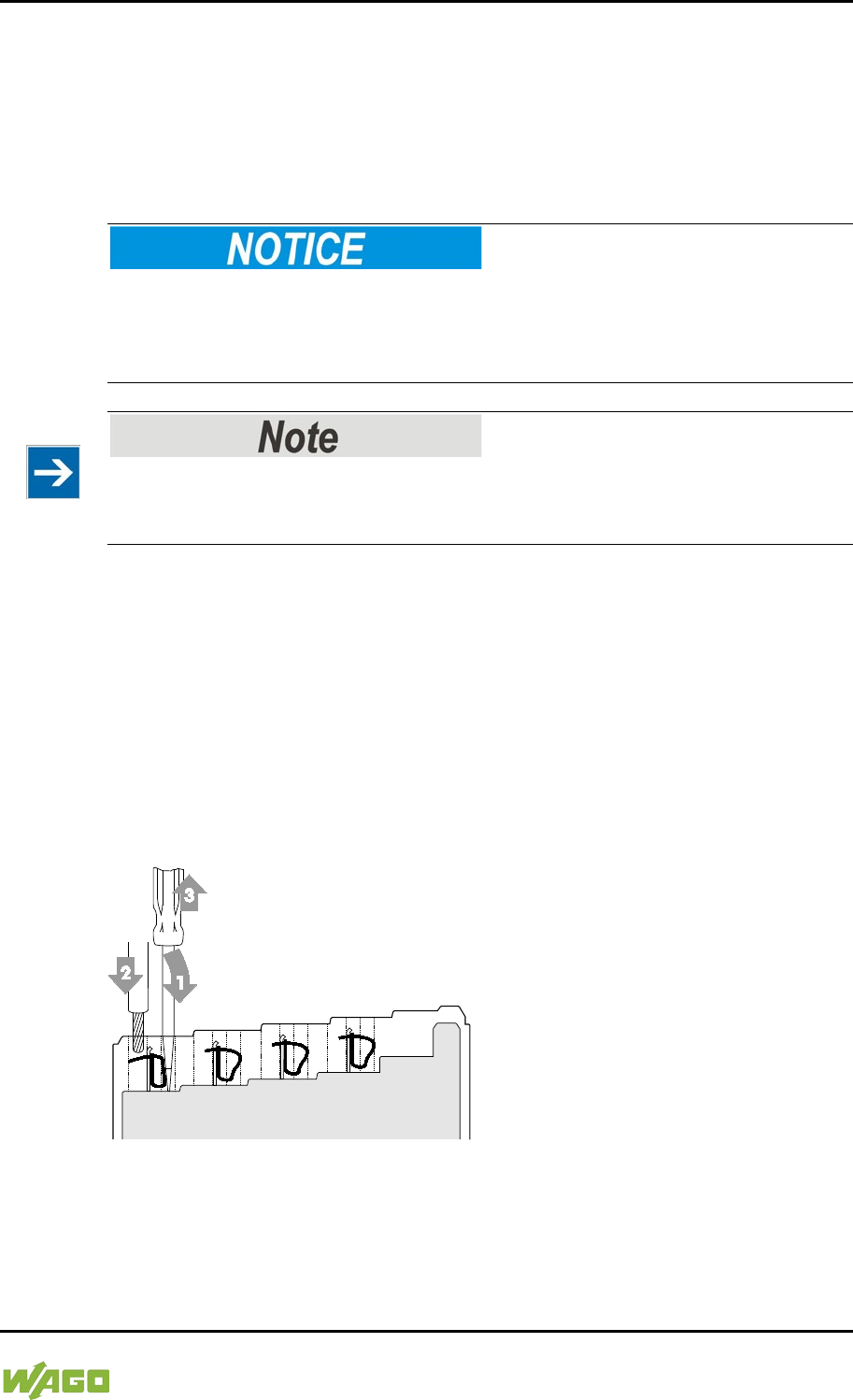
WAGO-I/O-SYSTEM 750 Connect Devices 79
750-8207 PFC200 CS 2ETH RS 3G
Manual
Draft version 1.2.1 from 2017-09-13, valid from FW Version 02.06.20(09)
6 Connect Devices
6.1 Connecting a Conductor to the CAGE CLAMP®
The WAGO CAGE CLAMP® connection is appropriate for solid, stranded and
finely stranded conductors.
Select conductor cross sections as required for current load!
The current consumed for field-side supply may not exceed 10 A. The wire cross
sections must be sufficient for the maximum current load for all of the I/O
modules to be supplied with power.
Only connect one conductor to each CAGE CLAMP® connection!
Only one conductor may be connected to each CAGE CLAMP® connection.
Do not connect more than one conductor at one single connection!
If more than one conductor must be routed to one connection, these must be
connected in an up-circuit wiring assembly, for example using WAGO feed-
through terminals.
1. To open the CAGE CLAMP® insert the actuating tool into the opening
above the connection.
2. Insert the conductor into the corresponding connection opening.
3. To close the CAGE CLAMP® simply remove the tool - the conductor is then
clamped firmly in place.
Figure 27: Connecting a Conductor to a CAGE CLAMP®
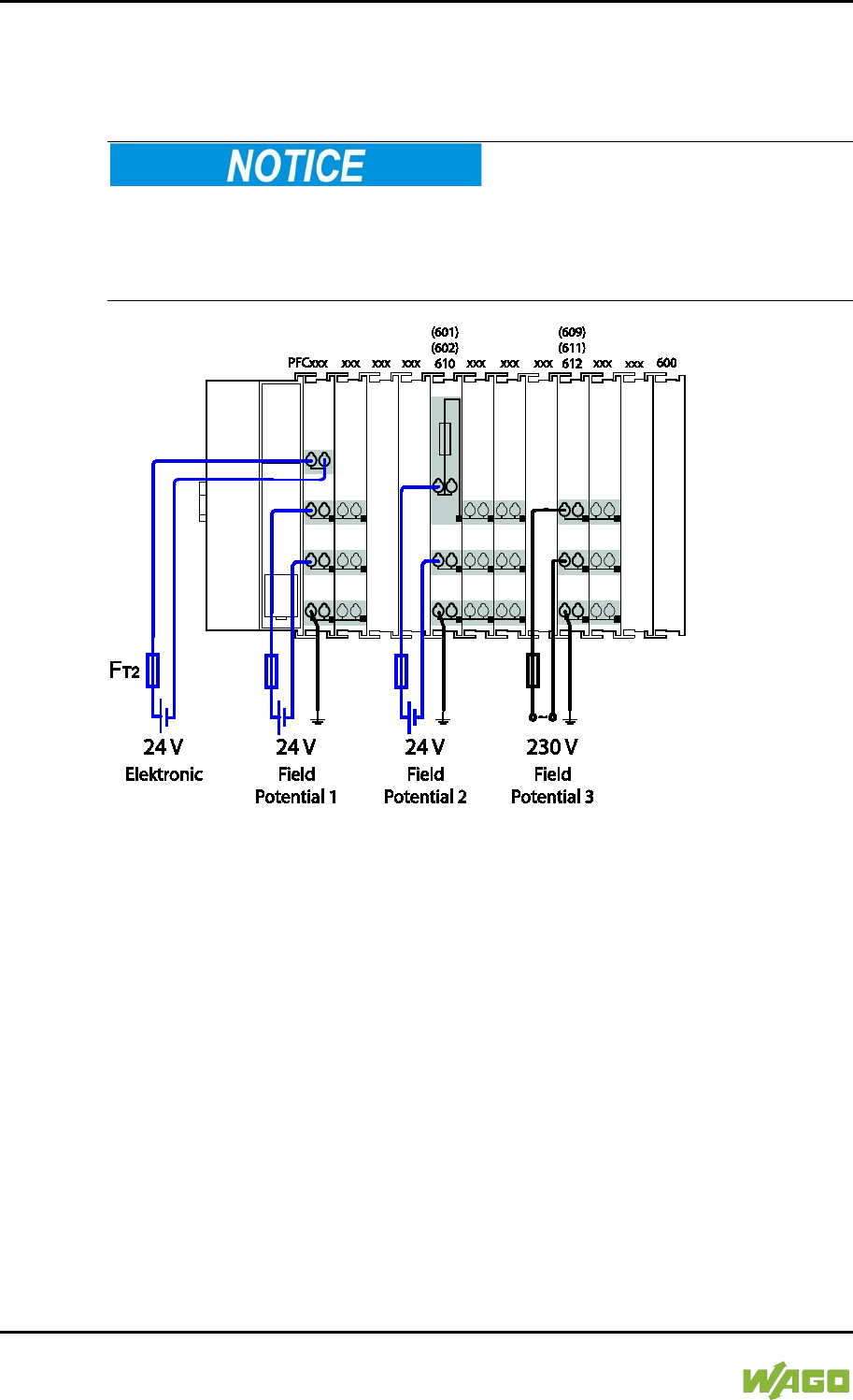
80 Connect Devices WAGO-I/O-SYSTEM 750
750-8207 PFC200 CS 2ETH RS 3G
Manual
Draft version 1.2.1 from 2017-09-13, valid from FW Version 02.06.20(09)
6.2 Power Supply Concept
6.2.1 Fuse Protection of the Electronic Circuit Power Supply
Only implement the electronic circuit power supply with a suitable fuse!
The electronic power supply of the controller must only be connected via a slow
blow 2A fuse, as shown in the following figure. The electronics may be damaged
with higher currents.
Figure 28: Fuse Protection of the Electronic Circuit Power Supply
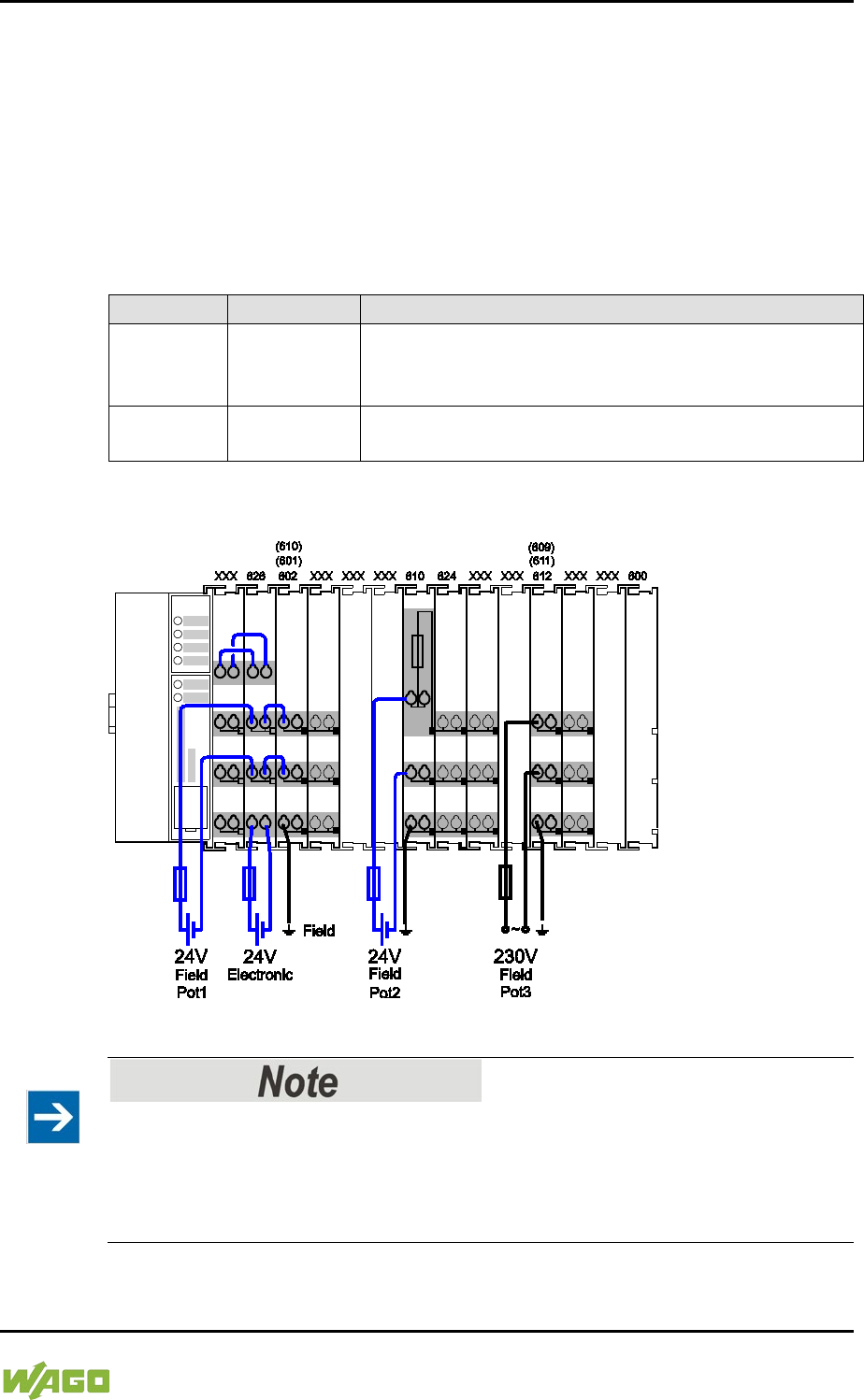
WAGO-I/O-SYSTEM 750 Connect Devices 81
750-8207 PFC200 CS 2ETH RS 3G
Manual
Draft version 1.2.1 from 2017-09-13, valid from FW Version 02.06.20(09)
6.2.2 Supplementary Power Supply Regulations
The WAGO-I/O-SYSTEM 750 can also be used in shipbuilding or offshore and
onshore areas of work (e. g. working platforms, loading plants). This is
demonstrated by complying with the standards of influential classification
companies such as Germanischer Lloyd and Lloyds Register.
Filter modules for 24 V supply are required for the certified operation of the
system.
Table 36: Filter Modules for 24 V Supply
Order No.
Name
Description
750-626
Supply Filter
Filter module for system supply and field supply
(24 V, 0 V), i. e. for
fieldbus coupler/controller and bus
power supply (750-613)
750-624
Supply Filter
Filter module for the 24 V field supply
(750-602, 750-601, 750-610)
Therefore, the following power supply concept must be absolutely complied with.
Figure 29: Power Supply Concept
Use a supply module for equipotential bonding!
Use an additional 750-601/ 602/ 610 Supply Module behind the 750-626 Filter
Module if you want to use the lower power jumper contact for equipotential
bonding, e.g., between shielded connections and require an additional tap for this
potential.

82 Commissioning WAGO-I/O-SYSTEM 750
750-8207 PFC200 CS 2ETH RS 3G
Manual
Draft version 1.2.1 from 2017-09-13, valid from FW Version 02.06.20(09)
7 Commissioning
7.1 Switching On the Controller
Before switching on the controller ensure that you
• have properly installed the controller
(see section “Installation”),
• have connected all required data cables (see section “Connections”) to the
corresponding interfaces and have secured the connectors by their
attached locking screws,
• have connected the electronics and field-side power supply
(see section “Connections”),
• have mounted the end module (750-600)
(see Section “Installation”),
• have performed appropriate potential equalization at your machine/system
(see System Description for 750-xxx) and
• have performed shielding properly (see System Description for 750-xxx).
To switch on both the controller and the connected I/O modules, switch on your
power supply unit.
Starting of the controller is indicated by a brief green flashing of all LEDs. After a
few seconds the SYS LED will signal successful boot-up of the controller.
The CODESYS 2.3 runtime system or e!RUNTIME is started at the same time.
Once the entire system has been successfully started, the SYS and I/O LEDs
light up green.
If there is an executable IEC 61131-3 program stored and running on the
controller, the RUN LED will light up green.
If no executable program is stored on the controller, or the mode selector switch
is set to STOP, this is likewise indicated by the RUN LED (see Section
“Diagnostics”> … > “Fieldbus/System Indication Elements”).

WAGO-I/O-SYSTEM 750 Commissioning 83
750-8207 PFC200 CS 2ETH RS 3G
Manual
Draft version 1.2.1 from 2017-09-13, valid from FW Version 02.06.20(09)
7.2 Determining the IP Address of the Host PC
To ensure that the host PC can communicate with the controller via ETHERNET,
both devices must be located in the same subnet.
To determine the IP address of the host PC (with the Microsoft Windows®
operating system) using the MS DOS prompt, proceed as follows:
1. Open the MS DOS prompt window.
To do this, enter the command “cmd” in the input field under Start >
Execute… > Open: (Windows® XP) or Start > Search programs/files
(Windows® 7) and then click [OK] or press [Enter].
2. In the MS DOS prompt enter the command “ipconfig” and then press
[Enter].
3. The IP address, subnet mask and standard gateway, including the
appropriate parameters, are displayed.

84 Commissioning WAGO-I/O-SYSTEM 750
750-8207 PFC200 CS 2ETH RS 3G
Manual
Draft version 1.2.1 from 2017-09-13, valid from FW Version 02.06.20(09)
7.3 Setting an IP Address
In the controller's initial state the following IP addresses are active for the
ETHERNET interface (Port X1 and Port X2):
Table 37: Default IP Addresses for ETHERNET Interfaces
Ethernet interface
Default setting
X1/X2
Dynamic assignment of IP address using “Dynamic Host
Configuration Protocol” (DHCP)
Adapt IP addressing for your specific system structure to ensure that the PC and
the controller can communicate with one another using one of the available
configuration tools (WBM, “WAGO Ethernet Settings”, CBM) (see section
“Configuration”).
Example for incorporating the controller (192.168.2.17) into an existing
network:
If the IP address of your host PC is 192.168.1.2, for example, then the controller
must be on the same subnet. That is, with the net mask 255.255.255.0, the first
three digits of the controller must match those of your PC. This yields the
following address range for the controller:
Table 38: Network Mask 255.255.255.0
Host PC
Subnet address range for the controller
192.168.1.2
192.168.1.3 … 192.168.1.254
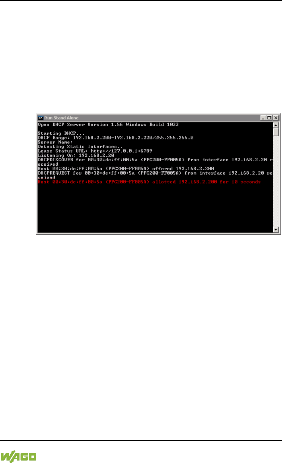
WAGO-I/O-SYSTEM 750 Commissioning 85
750-8207 PFC200 CS 2ETH RS 3G
Manual
Draft version 1.2.1 from 2017-09-13, valid from FW Version 02.06.20(09)
7.3.1 Assigning an IP Address using DHCP
The Controller can obtain dynamic IP addresses from a server (DHCP/BootP).
In contrast to fixed IP addresses, dynamically assigned addresses are not stored
permanently. Therefore, a BootP or DHCP server must be available each time
the controller is restarted.
If an IP address has been assigned by means of DHCP (default setting), it can be
determined through the settings and the output of the specific DHCP server.
In the example figure shown here, the corresponding output of “Open DHCP” is
presented.
Figure 30: “Open DHCP”, Example Figure
In conjunction with the DNS server associated with DHCP, the device can be
reached using its host name.
This name consists of the prefix “PFCx00-“ and the last six places of the MAC
address (in the example shown here: “00:30:DE:FF:00:5A”). The MAC address of
the device can be printed on the label on the side of the device.
The host name of the device in the example shown here is thus “PFC200-
FF005A”.
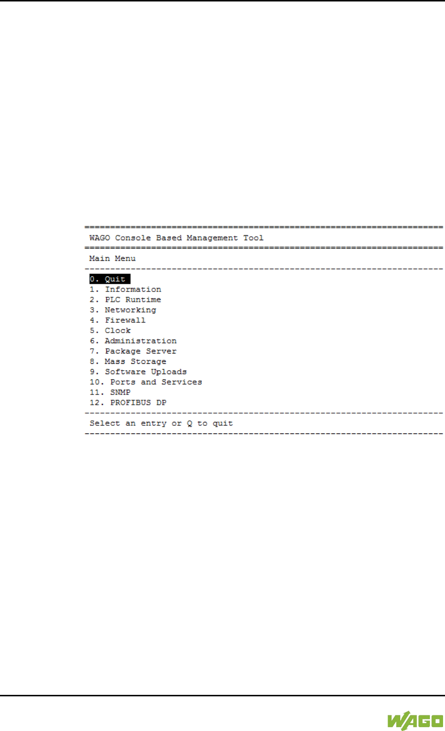
86 Commissioning WAGO-I/O-SYSTEM 750
750-8207 PFC200 CS 2ETH RS 3G
Manual
Draft version 1.2.1 from 2017-09-13, valid from FW Version 02.06.20(09)
7.3.2 Changing an IP Address Using the “CBM” Configuration
Tool via the Serial Interface
You can also assign a new IP address to the ETHERNET interfaces X1 and X2
using the “CBM” configuration tool provided on the Linux® console. More
information about “CBM” is given in the Section “Configuration.”
1. Link a PC to the X3 serial interface using a terminal program.
2. Log in to the Linux® system as a “super user.”
The user name and the password are provided in the Section “Users and
Passwords” > “Linux® User Group.”
3. Start the configuration tool by entering the command “cbm” on the
command line and then press [Enter].
Figure 31: CBM Starting Screen
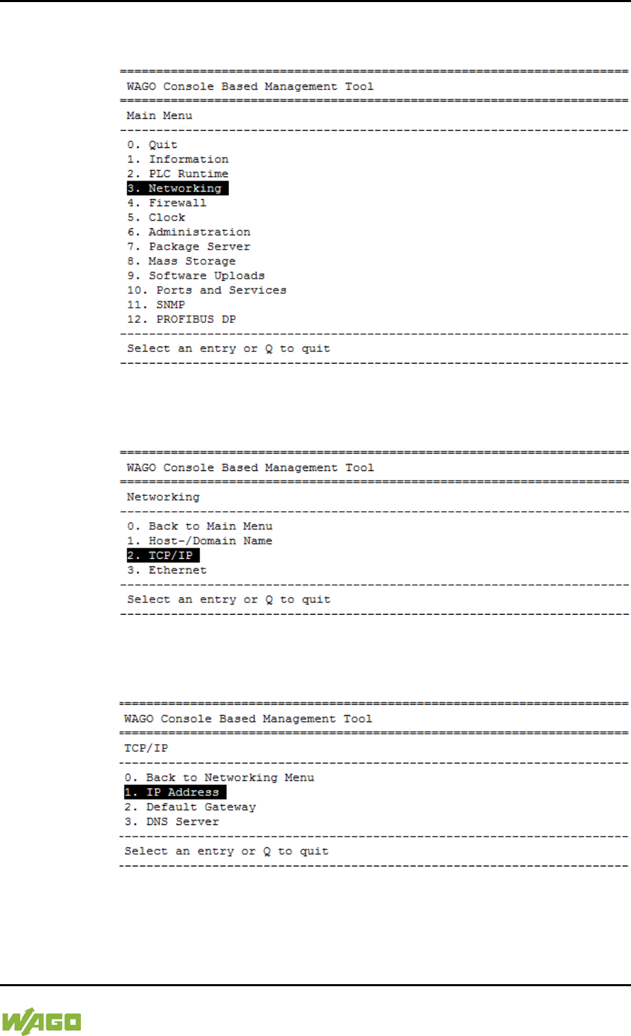
WAGO-I/O-SYSTEM 750 Commissioning 87
750-8207 PFC200 CS 2ETH RS 3G
Manual
Draft version 1.2.1 from 2017-09-13, valid from FW Version 02.06.20(09)
4. In the Main menu use the keyboard (arrow keys or numeric keypad) to
move to and select Networking and then press [Enter].
Figure 32: CBM – Selecting “Networking”
5. In the Networking menu select TCP/IP and press [Enter].
Figure 33: CBM – Selecting “TCP/IP”
6. In the menu TCP/IP select IP Address and press [Enter].
Figure 34: CBM – Selecting “IP address”
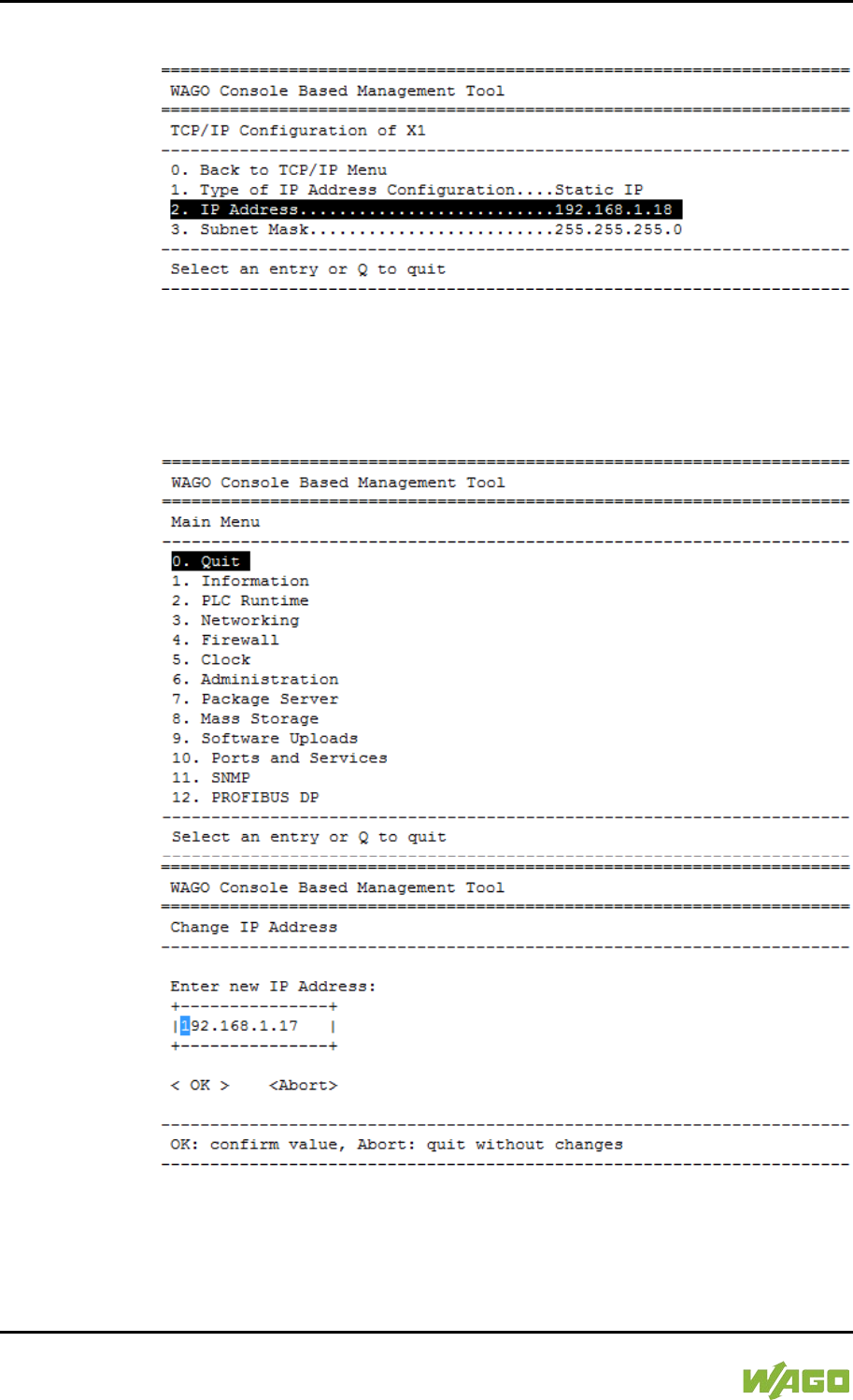
88 Commissioning WAGO-I/O-SYSTEM 750
750-8207 PFC200 CS 2ETH RS 3G
Manual
Draft version 1.2.1 from 2017-09-13, valid from FW Version 02.06.20(09)
7. In the menu TCP/IP Configuration select IP Address and press [Enter].
Figure 35: CBM – Selecting the IP Address
8. In the menu Change IP Address enter the new IP address and confirm by
clicking [OK]. If you want to return to the main menu without making
changes, click [Abort].
Figure 36: CBM – Entering a New IP Address
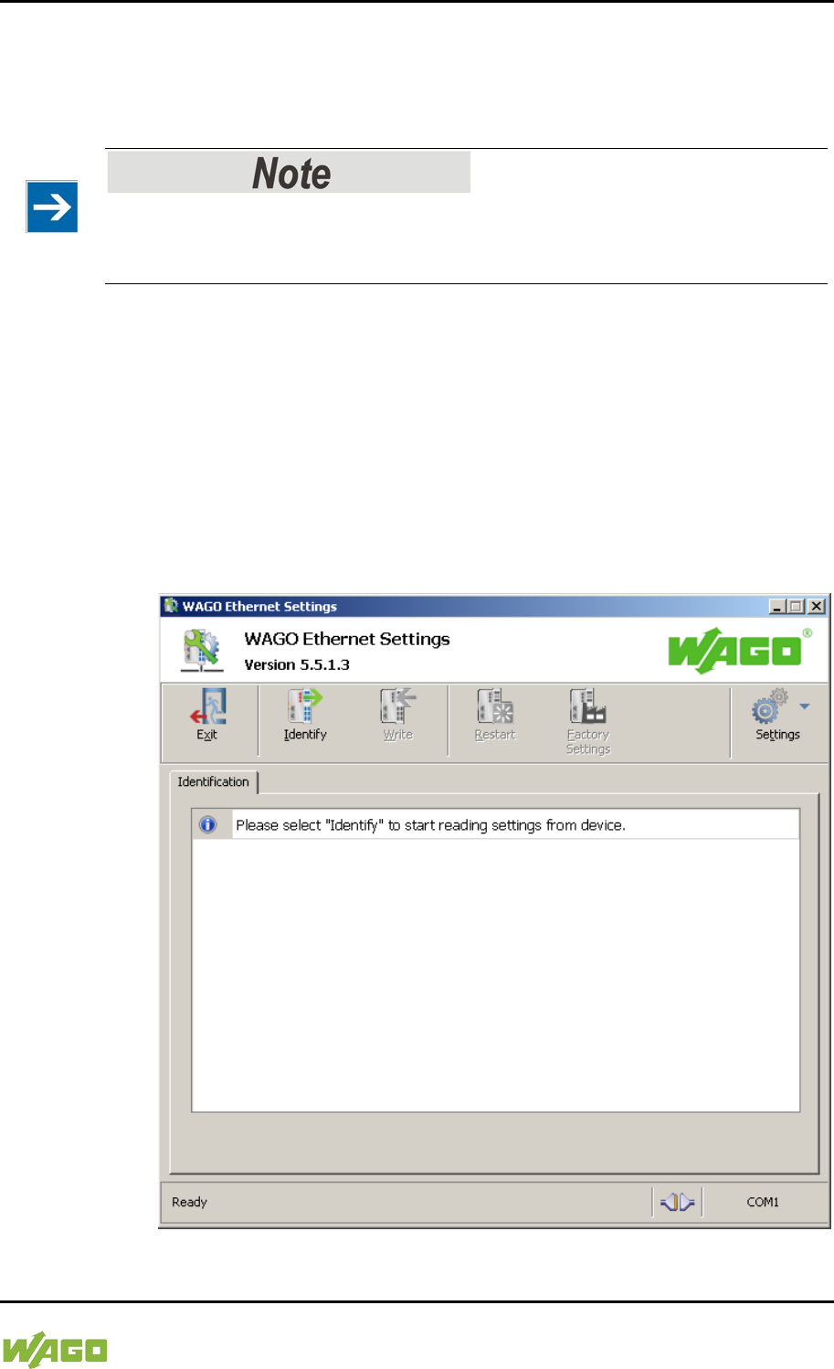
WAGO-I/O-SYSTEM 750 Commissioning 89
750-8207 PFC200 CS 2ETH RS 3G
Manual
Draft version 1.2.1 from 2017-09-13, valid from FW Version 02.06.20(09)
7.3.3 Changing an IP Address using “WAGO Ethernet Settings”
The Microsoft Windows® application “WAGO Ethernet Settings” is a software
used to identify the controller and configure network settings.
Observe the software version!
To configure the controller use at least Version 6.4.1.1 dated 2015-06-29 of
“WAGO Ethernet Settings”!
You can use WAGO communication cables or WAGO radio adapters or even the
IP network for data communication.
1. Switch off the power supply to the controller.
2. Connect the 750-920 communication cable to the Service interface on the
controller and to a serial interface of your PC.
3. Switch the power supply to the controller on again.
4. Start the “WAGO Ethernet Settings” program.
Figure 37: “WAGO Ethernet Settings” – Starting Screen (Example)
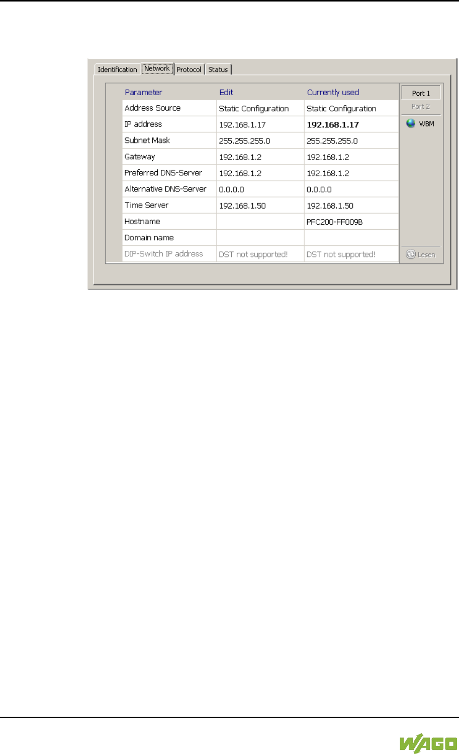
90 Commissioning WAGO-I/O-SYSTEM 750
750-8207 PFC200 CS 2ETH RS 3G
Manual
Draft version 1.2.1 from 2017-09-13, valid from FW Version 02.06.20(09)
5. Click [Identify] to read in and identify the connected controller.
6. Select the “Network” tab:
Figure 38: “WAGO Ethernet Settings” – “Network” Tab
7. To assign a fixed address, select “Static configuration” on the “Source” line
under “Input”. DHCP is normally activated as the default setting.
8. In the column “Input” enter the required IP address and, if applicable, the
address of the subnet mask and of the gateway.
9. Click on [Write] to accept the address in the controller. (If necessary,
“WAGO Ethernet Settings” will restart your controller. This action may
require about 30 seconds.)
10. You can now close “WAGO Ethernet Settings”, or make other changes
directly in the Web-based Management system as required. To do this,
click on [WBM] at the right in the window.

WAGO-I/O-SYSTEM 750 Commissioning 91
750-8207 PFC200 CS 2ETH RS 3G
Manual
Draft version 1.2.1 from 2017-09-13, valid from FW Version 02.06.20(09)
</dg_
7.3.4 Temporarily Setting a Fixed IP Address
This procedure temporarily sets the IP address for the X1 interface to the fixed
address “192.168.1.17”.
When the switch is enabled, the fixed address is also used for interface X2.
When the switch is disabled, the original address setting for interface X2 is not
changed.
No reset is performed.
To make this setting, set the mode selector switch to STOP and press and hold
the Reset button (RST) for longer than 8 seconds.
Execution of the setting is signaled by the “SYS” LED flashing orange.
To cancel this setting, perform a software reset or switch off the controller and
then switch it back on.
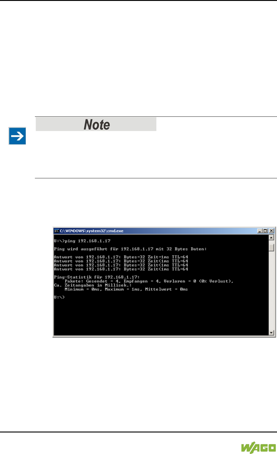
92 Commissioning WAGO-I/O-SYSTEM 750
750-8207 PFC200 CS 2ETH RS 3G
Manual
Draft version 1.2.1 from 2017-09-13, valid from FW Version 02.06.20(09)
7.4 Testing the Network Connection
Carry out a ping network function to check whether you can reach the controller
at the IP address you have assigned in the network.
1. Open the MS DOS prompt window.
To do this, enter the command “cmd” in the input field under Start >
Execute… > Open: (Windows® XP) or Start > Search programs/files
(Windows® 7) and then click [OK] or press [Enter].
2. In the MS DOS window, enter the command “ping” and the IP address of
the controller (for example, ping 192.168.1.17)and then press [Enter].
Host entries in the ARP table!
It may also be useful to delete the current host entries in the ARP table with the
command “arp -d *” before executing the “ping” command (as administrator in
Windows® 7). This ensures that older entries will not impair the success of the
“ping” command.
3. Your PC sends out a query that is answered by the controller. This reply
appears in the MS DOS prompt window. If the error message “Timeout”
appears, the controller has not responded properly. You then need to check
your network settings.
Figure 39: Example of a Function Test
4. If the test is completed successfully, close the MS DOS window.

WAGO-I/O-SYSTEM 750 Commissioning 93
750-8207 PFC200 CS 2ETH RS 3G
Manual
Draft version 1.2.1 from 2017-09-13, valid from FW Version 02.06.20(09)
7.5 Changing Standard Passwords
Change passwords
The standard passwords are documented in these instructions and therefore do
not offer adequate protection! Change the passwords to meet your particular
needs!
To increase security all passwords should contain a combination of lower case
letters (a … z), upper case letters (A … Z), numbers (0 … 9), spaces and special
characters: (]!"#$%&'()*+,./:;<=>?@[\^_`{|}~-). Passwords should not contain
generally known names, dates of birth and other information that is easy to
guess.
Therefore change the standard passwords before commissioning the controller.
Standard passwords are issued for the user groups “WBM Users” and “Linux®
Users.”
The table in the Section “Function Description” > ... > “Users and Passwords” >
“WBM Users Group” shows the standard passwords for the WBM users. Proceed
as follows to change these passwords:
1. Connect the controller to a PC via one of the network interfaces (X1, X2).
2. Start a web browser program on the PC and call up the WBM of the
controller.
3. Log in on the controller as “admin” user with the standard password.
4. Change the password for all users on the WBM “Configuration of the users
for the WBM” page.
5. Select each user and enter a new password and confirm it.
The table in the Section “Functional Description” > ... > “Users and Passwords” >
“Linux® Users Group” shows the standard passwords for the Linux® users.
Proceed as follows to change these passwords:
1. Connect the controller to a PC via the serial interface (X3).
2. Start a terminal program on the PC.
3. Log in on the controller as user “root” with the standard password.
4. Change the password for all users with the “passwd root,” “passwd admin”
and “passwd user” commands.

94 Commissioning WAGO-I/O-SYSTEM 750
750-8207 PFC200 CS 2ETH RS 3G
Manual
Draft version 1.2.1 from 2017-09-13, valid from FW Version 02.06.20(09)
</dg_
7.6 Shutdown/Restart
Switch off the power supply to shut down the controller.
To perform a controller restart, press the Reset button as described in the
Section “Triggering Reset Functions” > “Software Reset (Restart).”
Alternatively, you can switch off the controller and switch it back on again.
Do not power cycle the controller after changing any parameters!
Some parameter changes require a controller restart for the changes to apply.
Saving changes takes time.
Do not power cycle the controller to perform a restart, i.e., changes may be lost
by shutting down the controller too soon.
Only restart the controller using the software reboot function. This ensures that
all memory operations are completed correctly and completely.

WAGO-I/O-SYSTEM 750 Commissioning 95
750-8207 PFC200 CS 2ETH RS 3G
Manual
Draft version 1.2.1 from 2017-09-13, valid from FW Version 02.06.20(09)
</dg_
7.7 Initiating Reset Functions
You can initiate various reset functions using the mode selector switch and the
Reset button (RST).
7.7.1 Warm Start Reset
The warm start reset function depends on the activated runtime system
(CODESYS 2 or e!RUNTIME).
7.7.1.1 CODESYS 2 Runtime System
</dg_
The CODESYS 2 application is reset on a warm start reset. This corresponds to
the WAGO I/O PRO IDE “Reset” command.
</dg_
To perform a warm start reset, set the mode selector switch to "Reset" and hold it
there for two to seven seconds.
Execution of the reset is signaled by the red “RUN LED” briefly going out when
the mode selector switch is released.
7.7.1.2 e!RUNTIME Runtime System
All e!RUNTIME applications are reset with a warm start reset. All global data is
set to its initialization values. This corresponds to the e!COCKPIT IDE “Reset
warm” command.
</dg_
To perform a warm start reset, set the mode selector switch to "Reset" and hold it
there for two to seven seconds.
Execution of the reset is signaled by the red “RUN LED” briefly going out when
the mode selector switch is released.
7.7.2 Cold Start Reset
The cold start reset function depends on the activated runtime system
(CODESYS 2 or e!RUNTIME).
7.7.2.1 CODESYS 2 Runtime System
</dg_
On a cold start reset the CODESYS 2 application is reset and the memory
containing the retain variables is cleared.
This corresponds to the WAGO I/O PRO IDE “Reset (Cold)” command.
</dg_
To perform a cold start reset, set the mode selector switch to “Reset” and hold it
there for more than seven seconds.
Execution of the reset is signaled after seven seconds by the “RUN” LED going
out for an extended period. You can then release the mode selector switch.
7.7.2.2 e!RUNTIME Runtime System
</dg_

96 Commissioning WAGO-I/O-SYSTEM 750
750-8207 PFC200 CS 2ETH RS 3G
Manual
Draft version 1.2.1 from 2017-09-13, valid from FW Version 02.06.20(09)
All e!RUNTIME applications are reset with a cold start reset. All global data and
the retain variables are set to their initialization values.
This corresponds to the e!COCKPIT IDE “Reset Cold” command.
</dg_
To perform a cold start reset, set the mode selector switch to “Reset” and hold it
there for more than seven seconds.
Execution of the reset is signaled after seven seconds by the “RUN” LED going
out for an extended period. You can then release the mode selector switch.
</dg_
7.7.3 Software Reset
The controller is restarted on a software reset.
To perform a software reset, set the mode selector switch to RUN or STOP and
then press the Reset button (RST) for one to eight seconds.
All LEDs will light up briefly in green to signal reset completion.

WAGO-I/O-SYSTEM 750 Commissioning 97
750-8207 PFC200 CS 2ETH RS 3G
Manual
Draft version 1.2.1 from 2017-09-13, valid from FW Version 02.06.20(09)
7.8 Configuration
The following methods are available for configuring the controller:
• Access to the Web-based management system via the PC using an
Internet browser (“Configuration using Web-Based Management [WBM]”)
• Access to the “Console-Based Management” system (CBM) via the PC
using a terminal program (via ETHERNET and/or RS-232 interface;
“Configuration Using a Terminal Program”)
• Access via the CODESYS PLC program using the WagoConfigToolLIB.lib
library (“Appendix” > “WagoConfigToolLIB.lib”)
• Access via the PC using “WAGO Ethernet Settings” (“Configuration Using
‘WAGO Ethernet Settings’”).
The CBM is basically for the initial configuration and startup of the controller.
Therefore, it only provides a subset of the WBM parameters. For example,
parameters that cannot be displayed in a terminal window in a reasonable way
and are not necessary for initial startup are not displayed. You can find the
explanations of the parameters starting with the section “‘Information’ Page.”
98 Commissioning WAGO-I/O-SYSTEM 750
750-8207 PFC200 CS 2ETH RS 3G
Manual
Draft version 1.2.1 from 2017-09-13, valid from FW Version 02.06.20(09)
7.8.1 Configuration via Web-Based-Management (WBM)
The HTML pages (from here on referred to as “pages”) of the Web-Based
Management are used to configure the controller. Proceed as follows to access
the WBM using an Internet browser:
1. Connect the controller to the ETHERNET network via the ETHERNET
interface X1.
2. To access the pages, enter “https://” followed by the controller's IP address
and “/wbm” in the address line of your browser, e.g.,
“https://192.168.1.17/wbm.”
Note that the PC and the controller must be located within the same subnet
(see Section “Setting an IP Address”). If you do not know the IP address
and cannot determine it, switch the controller to the pre-set address
“192.168.1.17” using the “Fixed IP address” function (see Section “Initiate
Reset Functions” > “Set Fixed IP Address”).
If you have installed a DHCP server on your PC and would like to access WBM
through DHCP, use the other interface. You can find detailed information about
this in the section “Assigning an IP Address Using DHCP.”
Displaying the Controller Start Page
If the controller does not display the start page, ensure that your Internet browser
settings permit the bypassing of the proxy server for local addresses. Also check
whether your PC is located in the same subnet as the controller.
Take usage by the CODESYS program into account
If the controller is at capacity due to a CODESYS program, this may result in
slower processing in the WBM. As a result, timeout errors are sometimes
reported in some circumstances. It is therefore important to stop the CODESYS
application prior to performing complicated configurations using WBM.
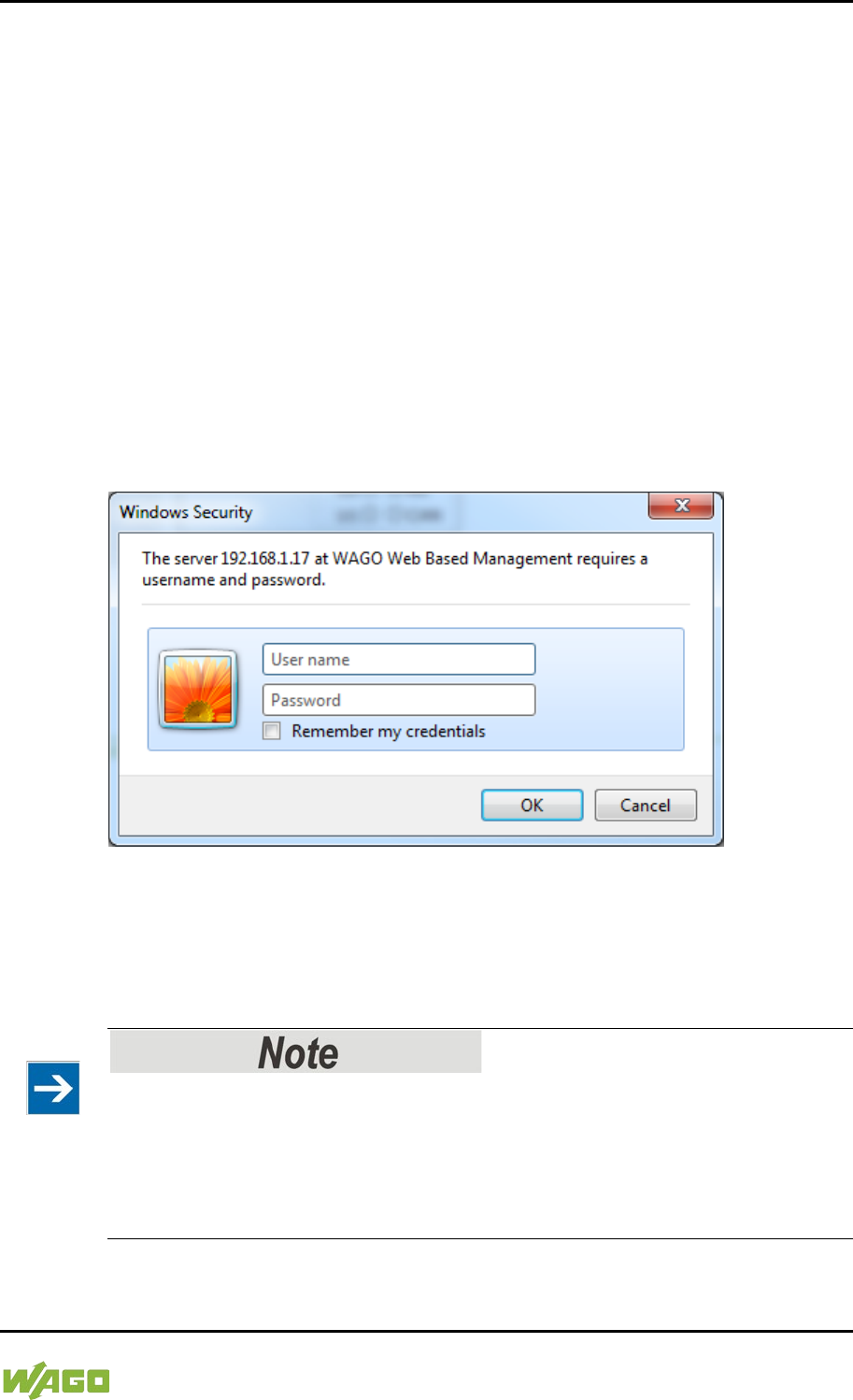
WAGO-I/O-SYSTEM 750 Commissioning 99
750-8207 PFC200 CS 2ETH RS 3G
Manual
Draft version 1.2.1 from 2017-09-13, valid from FW Version 02.06.20(09)
Some pages of the WBM are accessible only for certain users. They are only
displayed if you have logged into the WBM. You can access the login form via
the “Login” link. Pages which cannot be accessed with your current user name
are already grayed out in the navigation. You can nevertheless select the entries
in the navigation bar and are then routed directly to the login form.
As soon as you have logged in, your current user name is displayed in the
header of the WBM. By clicking the “Logout” link you can log out again and then
log in again with a different user name. When using the WBM without logging in,
you are granted “Guest” access rights.
You must be logged into the WBM in order to have write or read access to (most)
parameters. This is checked with every access to the device.
If you have disabled cookies in your browser, you can continue to use the WBM
as long as you move directly inside it. However, if you fully reload the website
(e.g., with F5), you must log in again since the browser is then not able to store
the data of your login session.
Figure 40: Entering Authentication
7.8.1.1 WBM User Administration
To allow settings to be made only by a select number of users, limit access to
WBM functions through User Administration.
Change passwords
The standard passwords are documented in these instructions and thus do not
offer adequate protection. Change the passwords to meet your particular needs.
See Section “Administration - Users Page.”
If you do not change these passwords, a warning will appear each time you call
up a website after logging in.
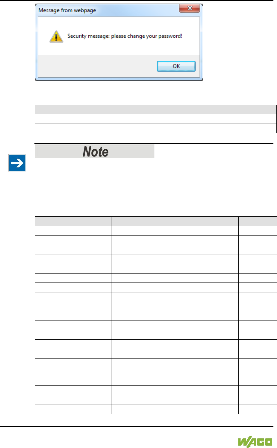
100 Commissioning WAGO-I/O-SYSTEM 750
750-8207 PFC200 CS 2ETH RS 3G
Manual
Draft version 1.2.1 from 2017-09-13, valid from FW Version 02.06.20(09)
Figure 41: Password Reminder
Table 39: User Settings in the Default State
Users
Password
user
user
admin
wago
Observe access rights
Users in WBM are authorized exclusively for access to websites. User
administration for controller applications is configured separately.
Access to the WBM pages is as follows:
Table 40: Access Rights for WBM Pages
Navigation
WBM page
User
Information
Status Information
guest
PLC Runtime
– Information
PLC Runtime Information
guest
– General Configuration
General PLC Runtime Configuration
user
– WebVisu
PLC WebVisu
guest
Networking
– Host/Domain Name
Configuration of Host and Domain Name
user
– TCP/IP
TCP/IP Configuration
user
– Ethernet
Ethernet Configuration
user
Firewall
– General Configuration
General Firewall Configuration
user
– MAC Address Filter
Configuration of MAC Address Filter
user
– User Filter
Configuration of User Filter
user
Clock
Configuration of Time and Date
user
Administration
– Users
Configuration of the users for the Web-
based Management
admin
– Create Image
Create bootable Image
admin
– Serial Interface
Configuration of Serial Interface RS233
admin
– Service Interface
Configuration of Service Interface
admin

WAGO-I/O-SYSTEM 750 Commissioning 101
750-8207 PFC200 CS 2ETH RS 3G
Manual
Draft version 1.2.1 from 2017-09-13, valid from FW Version 02.06.20(09)
Table 40: Access Rights for WBM Pages
Navigation
WBM page
User
– Reboot
Reboot Controller
admin
Package Server
– Firmware Backup
Firmware Backup
admin
– Firmware Restore
Firmware Restore
admin
– System Partition
System Partition
admin
Mass Storage
Mass Storage
admin
Software Uploads
Software Uploads
admin
Ports and Services
– Network Services
Configuration of Network Services
user
– NTP Client
Configuration of NTP Client
user
– PLC Runtime Services
Configuration of PLC Runtime Services
user
– SSH
SSH Server Settings
user
– TFTP
TFTP Server
user
– DHCP
DHCP Configuration
user
– DNS
Configuration of DNS Service
user
– MODBUS
MODBUS Services Configuration
user
SNMP
– General Configuration
Configuration of general SNMP
parameters
admin
– SNMP v1/v2c
Configuration of SNMP v1/v2c parameters
admin
– SNMP v3
Configuration of SNMP v3 Users
admin
Diagnostic
Diagnostic Information
guest
Modem
Configuration of internal 3G Modem
admin
OpenVPN / IPsec
Configuration of OpenVPN / IPsec
admin
Security
Security Settings
admin
Legal Information
– Open Source Licenses
Open Source Licenses
guest
– WAGO Licenses
WAGO Licenses
guest
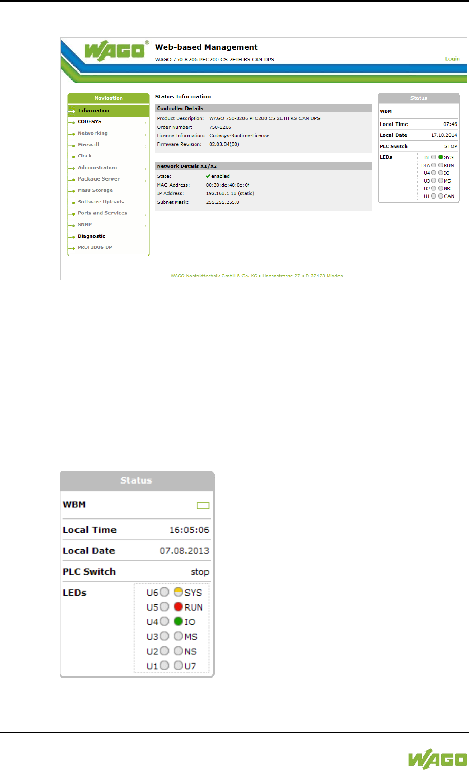
102 Commissioning WAGO-I/O-SYSTEM 750
750-8207 PFC200 CS 2ETH RS 3G
Manual
Draft version 1.2.1 from 2017-09-13, valid from FW Version 02.06.20(09)
7.8.1.2 General Information about the Page
Figure 42: WBM Browser Window (Example)
The device name is displayed in the header of the browser window. When the
user has logged out, a [Login] button is displayed on the right in the header line,
when logged in a [Logout] button is displayed.
The navigation tree is shown on the left of the browser window. You can use this
navigation tree to go to the individual pages and, where provided, subpages
included in these pages. Some pages can only be called after a successful login.
To log in click the [Login] button and enter the user name and password in the
login window.
A status area with the following elements is displayed on the right:
Figure 43: WBM Status Information (Example)

WAGO-I/O-SYSTEM 750 Commissioning 103
750-8207 PFC200 CS 2ETH RS 3G
Manual
Draft version 1.2.1 from 2017-09-13, valid from FW Version 02.06.20(09)
• WBM status:
This indicates whether the WBM is currently communicating with the device
in the background. In other words, one or more requests have been sent
and the browser is waiting for a response. Movement is then visible in the
graphic. This occurs when data is read on initial call-up of the page, when
the user has sent off a change form or when data is reloaded automatically
in cycles, e.g., the contents of the status area.
• Local Time:
Local time on the device
• Local Date:
Local date on the device
• PLC Switch:
Setting of the mode selector switch
• LEDs:
This indicates the status of the device LEDs. All LEDs are graphically
represented and are labeled with their particular designation (e.g., SYS,
RUN, ...). The following colors are possible:
- gray:
LED is off.
- full color (green, red, yellow, orange):
The LED is activated in the particular color.
- half color:
The LED is flashing in the corresponding color. The other half of the
surface is then either gray or also colored. The latter case indicates that the
LED is flashing sequentially in different colors.
A tooltip containing more detailed information opens as long as the cursor
is positioned over an LED. The text that is displayed also contains the
message that put the LED into its current status. The time of the message
is also shown.
The states displayed in the WBM will not always correspond at the precise
time to those on the controller. Data has a runtime during transmission and
can only be queried at a certain interval. The time period between two
queries is 30 seconds.
The contents of the individual pages and sub-pages are explained in the
following sections.

104 Commissioning WAGO-I/O-SYSTEM 750
750-8207 PFC200 CS 2ETH RS 3G
Manual
Draft version 1.2.1 from 2017-09-13, valid from FW Version 02.06.20(09)
Do not power cycle the controller after changing any parameters!
Some parameter changes require a controller restart for the changes to apply.
Saving changes takes time.
Do not power cycle the controller to perform a restart, i.e., changes may be lost
by shutting down the controller too soon.
Only restart the controller using the software reboot function. This ensures that
all memory operations are completed correctly and completely.

WAGO-I/O-SYSTEM 750 Commissioning 105
750-8207 PFC200 CS 2ETH RS 3G
Manual
Draft version 1.2.1 from 2017-09-13, valid from FW Version 02.06.20(09)
7.8.1.3 “Status Information” Page
The following tables explain the parameters listed on this page:
7.8.1.3.1 “Controller Details” Group
This group displays the properties of the controller.
Table 41: WBM “Status Information” Page – “Controller Details” Group
Parameter
Explanation
Product Description
Controller identification
Order Number
Item number of the controller
License Information
Notification that the CODESYS runtime system is
available
Firmware Revision
Firmware status
7.8.1.3.2 “Network Details (Xn)” Group(s)
This group displays the network and interface properties of the controller.
If the switch is enabled, one group (“Network Details X1/X2”) is shown for both
connections.
If the switch is disabled, a separate group (“Network Details X1” / “Network
Details X2”) is shown for each connection.
Table 42: WBM “Status Information Page – “Network Details (Xn)” Group(s)
Parameter
Explanation
State
Status of the ETHERNET interface
(enabled/disabled)
Mac Address
MAC address identifies and addresses the controller
IP Address
Current IP address of the controller and (in brackets)
the reference type (static/bootp/dhcp)
Subnet Mask
Current subnet mask of the controller
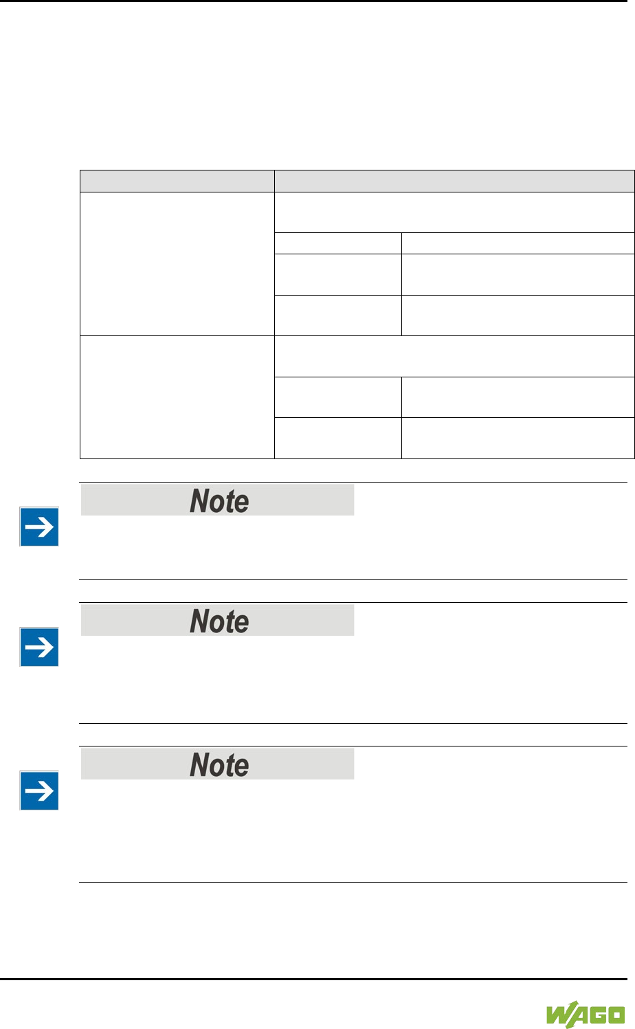
106 Commissioning WAGO-I/O-SYSTEM 750
750-8207 PFC200 CS 2ETH RS 3G
Manual
Draft version 1.2.1 from 2017-09-13, valid from FW Version 02.06.20(09)
7.8.1.4 “General PLC Runtime Configuration” Page
The settings for the boot project created with the programming software are given
on the “General PLC Runtime Configuration” page.
7.8.1.4.1 “General PLC Runtime Configuration” Group
Table 43: WBM “General PLC Runtime Configuration” Page – “General PLC Runtime Configuration”
Group
Parameters
Explanation
PLC runtime version
Select here the PLC runtime system to be enabled.
None
No runtime system is enabled.
CODESYS 2
CODESYS 2 runtime system is
enabled.
e!RUNTIME
e!RUNTIME runtime system is
enabled.
Home directory on memory
card enabled
Define if the home directory for the runtime system
should be moved to the memory card.
Disabled
The home directory is stored in
the internal memory.
Enabled
The home directory is moved to
the memory card.
All data is deleted when switching the runtime system!
The runtime system’s home directory is completely deleted when switching the
runtime system!
Insert a memory card before switching the home directory!
When moving the home directory to the memory card, insert a memory card
formatted to support file system. Only the first partition of a memory card can be
accessed at /media/sd and can be used as the home directory.
Perform a reset before switching the home directory!
Stop IEC-61131 applications in use before switching the home directory of the
runtime system.
Restore the device to its initial state using the “Reset” function. Any boot project
is deleted.
Click [Submit] to apply the change.
The runtime system change is effective immediately.

WAGO-I/O-SYSTEM 750 Commissioning 107
750-8207 PFC200 CS 2ETH RS 3G
Manual
Draft version 1.2.1 from 2017-09-13, valid from FW Version 02.06.20(09)
The home directory change only takes effect after restarting the controller. For
this purpose, use the WBM reboot function. Do not shut down the controller too
early!
108 Commissioning WAGO-I/O-SYSTEM 750
750-8207 PFC200 CS 2ETH RS 3G
Manual
Draft version 1.2.1 from 2017-09-13, valid from FW Version 02.06.20(09)
7.8.1.5 “PLC Runtime Information” Page
All information about the enabled runtime system and PLC program created in
the programming software is provided on the “PLC Runtime Information” page.
7.8.1.5.1 “PLC Runtime” Group
Table 44: WBM “PLC Runtime Information” Page – “PLC Runtime” Group
Parameters
Explanation
Version
The version of the currently activated runtime
system is shown here.
If the runtime system is disabled, “None” is
displayed and the subsequent fields of this group
are disabled.
Web Server Version
This shows the version number of the web server.
This field is only visible when CODESYS 2 is
enabled as the runtime system.
State
The PLC operating state is shown. This field is only
visible when CODESYS 2 is enabled as the runtime
system.
STOP
PLC program is not executed.
RUN
PLC program is executed.
Number of Tasks
The number of tasks in the PLC program is shown.
This field is only visible when CODESYS 2 is
enabled as the runtime system.
7.8.1.5.2 “Project Details” Group
This group is only visible if CODESYS 2 is enabled as the runtime system.
Table 45: WBM “PLC Runtime Information” Page – “Project Details” Group
Parameters
Explanation
Date
Display of project information that the programmer
entered in the PLC program (in programming
software under Project > Project Information...).
The information only appears when a PLC program
is run.
Descriptive texts up to 1024 characters long are
given under “Description.”
Title
Version
Author
Description

WAGO-I/O-SYSTEM 750 Commissioning 109
750-8207 PFC200 CS 2ETH RS 3G
Manual
Draft version 1.2.1 from 2017-09-13, valid from FW Version 02.06.20(09)
7.8.1.5.3 “Task n” Group(s)
This group is only visible if CODESYS 2 is enabled as the runtime system.
One dedicated group is displayed for each task when the PLC program is
executed. As a rule, only the group title is displayed with the task number, the
task name and the task ID.
Click [+] to expand the group and display the following information.
Table 46: WBM “PLC Runtime Information” Page – “Task n” Group(s)
Parameters
Explanation
Cycle count
Number of task cycles since the system start
Cycle time (µsec)
Currently measured task cycle time for the task
Cycle time min (µsec)
Minimum task cycle time for the task since the
system start
Cycle time max (µsec)
Maximum task cycle time for the task since the
system start
Cycle time avg (µsec)
Average task cycle time since the system start
Status
Task status (e.g., RUN, STOP)
Mode
Task execution mode (e.g., in cycles)
Priority
Set task priority
Interval (msec)
Set task interval
To hide this information, click [–].
110 Commissioning WAGO-I/O-SYSTEM 750
750-8207 PFC200 CS 2ETH RS 3G
Manual
Draft version 1.2.1 from 2017-09-13, valid from FW Version 02.06.20(09)
7.8.1.6 “PLC WebVisu” Page
The settings for the web visualization created in the runtime system are shown
on the “PLC WebVisu” page.
7.8.1.6.1 “Web Server Configuration” Group
Table 47: WBM “PLC WebVisu” Page – “Web Server Configuration” Group
Parameters
Explanation
CODESYS 2 Webserver
State
This indicates the status (enabled/disabled) of the
CODESYS 2 web server.
e!RUNTIME Webserver
State
This indicates the status (enabled/disabled) of the
e!
RUNTIME web server.
Default Webserver
Choose here whether the Web-based Management
or web visualization of the runtime system should be
displayed when only entering the IP address of the
controller.
Web-based
Management
The Web-based Management is
displayed.
Web-Visu
The web visualization of the runtime
system is displayed.
Click [Submit] to apply change. The change is effective immediately.
In its default setting, the WBM is called up when only entering the IP address.
To update the display after switching, enter the IP address again in the address
line of the web browser.
To display the web visualization, the web server must be enabled (in WBM under
“Ports and Services” -> “PLC Runtime Services”) and there must be a suitably
configured application.
Regardless of the default web server setting, the WBM can be called up at any
time with “https://<IP address>/wbm” and the web visualization with
“https://<IP address>/webvisu.”
You can obtain additional information on CODESYS 2 web visualization in the
section of the same name.
Possible error messages when calling up the web visualization
The “500 − Internal Server Error” message indicates that the web server is not
enabled.
A page with the header “WebVisu not available” means that no application has
been loaded in the controller using web visualization.

WAGO-I/O-SYSTEM 750 Commissioning 111
750-8207 PFC200 CS 2ETH RS 3G
Manual
Draft version 1.2.1 from 2017-09-13, valid from FW Version 02.06.20(09)
7.8.1.7 “Configuration of Host and Domain Name” Page
The settings for the general TCP/IP parameters are found on the “Configuration
of Host and Domain Name” page.
7.8.1.7.1 “HostName” Group
Table 48: WBM “Configuration of Host and Domain Name” Page – “Hostname” Group
Parameters
Explanation
Currently used
If you have selected dynamic assignment of an IP
address via DHCP, the name of the host currently
being used is displayed.
Configured
Enter here the hostname of your controller to be
used if the network interface is changed to a static
IP address or if no hostname is transmitted with a
DHCP response.
Click [Submit] to apply the change. The change is effective immediately.
If a hostname is supplied via a DHCP response, this is enabled in the system. If
there are several network interfaces with DHCP always the last received hostname
is valid.
If only the hostname configured here is to be valid, the configuration of the DHCP
server must be adapted so that no hostnames are transferred in the DHCP
response.
7.8.1.7.2 “Domain Name” Group
Table 49: WBM “Configuration of Host and Domain Name” Page – “Domain Name” Group
Parameters
Explanation
Currently used
The domain name currently used is displayed.
It may differ from the configured domain name if you
have selected dynamic assignment of an IP address
via DHCP or BootP.
Configured
Enter the domain name.
The default entry is “localdomain.lan”.
Click [Submit] to apply the change. The change is effective immediately.
If a domain name is supplied via a DHCP response, this is enabled in the system.
If there are several network interfaces with DHCP, the last received domain name
is always valid.
If only the domain name configured here is to be valid, the configuration of the
DHCP server must be adapted so that no domain names are transferred in the
DHCP response.

112 Commissioning WAGO-I/O-SYSTEM 750
750-8207 PFC200 CS 2ETH RS 3G
Manual
Draft version 1.2.1 from 2017-09-13, valid from FW Version 02.06.20(09)
</dg_
7.8.1.8 “TCP/IP Configuration” Page
The TCP/IP settings for the ETHERNET interfaces are shown on the “TCP/IP
configuration” page.
7.8.1.8.1 “IP Configuration (Xn)” Group(s)
If the switch is enabled, one group (“IP Configuration”) is shown for both
connections.
If the switch is disabled, a separate group (“IP Configuration X1” / “IP
Configuration X2”) is shown for each connection.
Table 50: WBM “TCP/IP Configuration” Page – “IP Configuration (Xn)” Group(s)
Parameters
Explanation
Configuration Type
Select a static or dynamic IP address.
Static IP
Static IP addressing
DHCP
Dynamic IP addressing
BootP
Dynamic IP addressing
IP Address
Enter here a static IP address. This is enabled if
“Static IP” is enabled in the Configuration Type
field.
Subnet Mask
Enter the subnet mask. This is enabled if “Static IP”
is enabled in the
Configuration Type
field.
Click [Submit] to apply changes. The changes are effective immediately.

WAGO-I/O-SYSTEM 750 Commissioning 113
750-8207 PFC200 CS 2ETH RS 3G
Manual
Draft version 1.2.1 from 2017-09-13, valid from FW Version 02.06.20(09)
7.8.1.8.2 “Default Gateway n” Groups
You can configure two default gateways. The controller transmits all network data
not going to a station on the local network to a default gateway. First the gateway
with the lowest metric is addressed. If this is not reached, the second gateway is
used. The selection is random if the metric is the same.
A default gateway can also be configured via DHCP. These default gateways are
given the metric 10, by which they are normally used before the static gateways.
Table 51: WBM “TCP/IP Configuration” Page – “Default Gateway n” Group
Parameters
Explanation
Gateway enabled
Set here whether the selected default gateway is to
be used.
Disabled
The default gateway is not used.
Enabled
The default gateway is used.
Destination Address
Enter here if any network devices or only a specific
network device or device pool is to be accessed.
“default”
Any network devices can be reached.
Network
address
Only a specific network device or
device from the set address pool can
be reached.
Destination Mask
Enter the subnet mask of the station.
If “default” is entered at Destination Address, the
value “0.0.0.0” must be entered here.
Gateway Address
Enter the address of the default gateway.
Gateway Metric
Set here a number as the metric. With multiple
default gateways, the metric defines the gateway to
which data packets are first sent. Priority is given to
the gateway with the lower metric. The default value
for the metric is 20.
The lowest value is 0.
The highest value is 4.294.967.295.
Click [Submit] to apply the change. The change is effective immediately.

114 Commissioning WAGO-I/O-SYSTEM 750
750-8207 PFC200 CS 2ETH RS 3G
Manual
Draft version 1.2.1 from 2017-09-13, valid from FW Version 02.06.20(09)
7.8.1.8.3 “DNS Server” Group
Table 52: WBM “TCP/IP Configuration” Page – “DNS Server” Group
Parameters
Explanation
Configured: None/
DNS Server n
The addresses of the defined DNS servers are
displayed. If no server has been defined,
“Configured: None” is displayed.
New Server IP
Add additional DNS addresses.
You can enter 10 addresses.
Additionally used
(assigned by DHCP)
The DNS servers assigned if necessary by DHCP
(or BootP) are displayed. If no DNS server has been
assigned by DHCP (or BootP), “none” is displayed.
Click [Delete] to remove the selected DNS server. The change is effective
immediately.
Click [Add] to add the entered DNS server. The change is effective immediately.

WAGO-I/O-SYSTEM 750 Commissioning 115
750-8207 PFC200 CS 2ETH RS 3G
Manual
Draft version 1.2.1 from 2017-09-13, valid from FW Version 02.06.20(09)
7.8.1.9 “Ethernet Configuration” Page
The settings for Ethernet TCP/IP are located on the “Ethernet Configuration”
page.
7.8.1.9.1 “Switch Configuration” Group
Table 53: WBM “Ethernet Configuration” Page – “Switch Configuration” Group
Parameter
Explanation
Interfaces
Enable or disable the switch.
Switched
Both interfaces are operated with one
IP address.
Separated
Each interface is operated with its own
IP address.
Port Mirror
Enable or disable the mirroring of the data traffic
between the ports.
None
Both Ethernet ports operating normally.
X1
The entire data traffic between X1 and
the PFC system is mirrored at port X2.
X2
The entire data traffic between X2 and
the PFC system is mirrored at port X1.
Fast Aging enabled
Set here the aging time of unused entries in the list
of MAC addresses with a port assignment to
external network stations.
Disabled
An unused address entry becomes
obsolete after 200 seconds.
Enabled
An unused address entry becomes
obsolete after 800 microseconds.
Broadcast Protection
Set here the broadcast limit for protection against
overloads.
Disabled
No limitation of broadcast packets.
1 % ... 5 %
Limitation of incoming broadcast
packets to the selected percentage of
the total possible data throughput
(10/100Mbit).
Rate Limit
Set here the basic limitation of the incoming data
traffic.
Disabled
No limitation of the incoming data traffic
64 kbps …
99 mbps
Limitation of the incoming data traffic to
the entered value
Click [Submit] to apply the change. The change is effective immediately.
7.8.1.9.2 “Interface Xn” Groups
One group (“Interface X1” / “Interface X2”) is displayed for each connection.

116 Commissioning WAGO-I/O-SYSTEM 750
750-8207 PFC200 CS 2ETH RS 3G
Manual
Draft version 1.2.1 from 2017-09-13, valid from FW Version 02.06.20(09)
Table 54: WBM “Ethernet Configuration” Page – “Interface Xn” Groups
Parameter
Explanation
Enabled
You can enable or disable the interface.
Autonegotiation on
When Autonegotiation is enabled, the connection
modalities are negotiated automatically
with the peer
devices.
Speed/Duplex
Select the transmission speed and the duplex
method:
10 Mbit half-duplex Information can only be
sent or received.
100 Mbit half-duplex
10 Mbit full-duplex
Information can be sent
and received
simultaneously.
100 Mbit full-duplex
Click [Submit] to apply changes. The changes are effective immediately.

WAGO-I/O-SYSTEM 750 Commissioning 117
750-8207 PFC200 CS 2ETH RS 3G
Manual
Draft version 1.2.1 from 2017-09-13, valid from FW Version 02.06.20(09)
7.8.1.10 “General Firewall Configuration” Page
7.8.1.10.1 “Global Firewall Parameters” Group
Table 55: WBM “General Firewall Configuration” Page – “Global Firewall Parameters” Group
Parameters
Explanation
Firewall enabled entirely
Enables/disables the complete functionality of the
firewall. This setting has the highest priority. If the
firewall is disabled, all other settings have no direct
effect. The configuration of the other parameters is
possible nevertheless so that you can set the
firewall parameters correctly before you enable the
firewall.
ICMP echo broadcast
protection
Enable or disable the “ICMP echo broadcast”
protection.
Max. UDP connections per
second
You can specify the maximum number of UDP
connections per second.
Max. TCP connections per
second
You can specify the maximum number of TCP
connections per second.
Click [Submit] to apply the change. The change is effective immediately.

118 Commissioning WAGO-I/O-SYSTEM 750
750-8207 PFC200 CS 2ETH RS 3G
Manual
Draft version 1.2.1 from 2017-09-13, valid from FW Version 02.06.20(09)
7.8.1.10.2 “Firewall Parameters Interface xxx” Group
These settings in this group refer to the configuration of the firewall at IP level.
Table 56: WBM “General Firewall Configuration” Page – “Firewall Parameter Interface Xn” Group
Parameters
Explanation
Firewall enabled for
Interface
Enable or disable the firewall for the specific
interface.
ICMP echo protection
Enable or disable the “ICMP echo” protection for the
respective interface.
ICMP echo limit per second
You can specify the maximum number of “ICMP
echo bursts” per second.
ICMP burst limit
(0 = disabled)
You can specify the maximum number of “ICMP
echo bursts” per second.
“0” = “Disabled”
Service enabled
Telnet
Enable or disable the
firewall for the respective
service.
The services themselves
must be enabled or
disabled separately on the
“Ports and Services” page.
FTP
FTPS
HTTP
HTTPS
I/O-CHECK
PLC Runtime
PLC WebVisu –
direct link (port 8080)
SSH
TFTP
BootP/DHCP
DNS
MODBUS TCP
MODBUS UDP
SNMP
Click [Submit] to apply the change. The change is effective immediately.

WAGO-I/O-SYSTEM 750 Commissioning 119
750-8207 PFC200 CS 2ETH RS 3G
Manual
Draft version 1.2.1 from 2017-09-13, valid from FW Version 02.06.20(09)
</dg_
7.8.1.11 “Configuration of MAC Address Filter” Page
You set the firewall configuration at ETHERNET level on this page.
The “MAC Address Filter Whitelist” contains a default entry with the following
values:
MAC address: 00:30:DE:00:00:00
MAC mask: ff:ff:ff:00:00:00
If you enable the default entry, this already allows communication between
different WAGO devices in the network.
Enable the MAC address filter before activation!
Before activating the MAC address filter, you must enter and activate your own
MAC address in the “MAC Address Filter Whitelist.”
Otherwise you cannot access the device via the ETHERNET. This also applies to
other services that are used by your device, e.g., the IP configuration via DHCP.
If the “MAC Address Filter Whitelist” does not contain the MAC address of your
DHCP server, your device will lose its IP settings after the next refresh cycle and
is then no longer accessible.
If the “MAC Address Filter Whitelist” does not contain an entry, the activation of
the filter is prevented.
If at least one activated address is entered, you will receive an appropriate
warning before activation, which you have to acknowledge.
The check described above is only performed in the WBM but not in the CBM!
7.8.1.11.1 “Global MAC Address Filter State” Group
Table 57: WBM “Configuration of MAC Address Filter” Page – “Global MAC Address Filter State”
Group
Parameters
Explanation
Filter enabled
Enable or disable the global MAC address filter
here.
Click [Submit] to apply change. The change is effective immediately.

120 Commissioning WAGO-I/O-SYSTEM 750
750-8207 PFC200 CS 2ETH RS 3G
Manual
Draft version 1.2.1 from 2017-09-13, valid from FW Version 02.06.20(09)
7.8.1.11.2 “MAC Address Filter State Xn” Group
Table 58: WBM “Configuration of MAC Address Filter” Page – “MAC Address Filter State Xn” Group
Parameters
Explanation
Filter enabled
Enable or disable here the MAC address filter for the
specific interface.
Click [Submit] to apply change. The change is effective immediately.
7.8.1.11.3 “MAC Address Filter Whitelist” Group
Table 59: WBM “Configuration of MAC Address Filter” Page – “MAC Address Filter Whitelist” Group
Parameters
Explanation
MAC address
Displays the MAC address of the relevant list entry.
MAC mask
This displays the MAC mask of the relevant list
entry.
Filter enabled
Enable or disable the filter for the relevant list entry
here.
…
MAC address
Enter here the MAC address for a new list entry.
You can enter 10 filters.
MAC mask
Enter the MAC mask for the new list entry here.
Filter enabled
Enable or disable the filter for the new list entry
here.
Click [Submit] to apply the change. The change is effective immediately.
Click the appropriate [Delete] button to remove an existing list entry. The change
is effective immediately.
Click [Add] to accept a new list entry. You can enter 10 filters. The change is
effective immediately.

WAGO-I/O-SYSTEM 750 Commissioning 121
750-8207 PFC200 CS 2ETH RS 3G
Manual
Draft version 1.2.1 from 2017-09-13, valid from FW Version 02.06.20(09)
7.8.1.12 “Configuration of User Filter” Page
7.8.1.12.1 “User Filter” Group
Table 60: WBM “Configuration of User Filter” Page – “User Filter” Group
Parameters
Explanation
Count
The number of configured user filters is displayed.
7.8.1.12.2 “User Filter n” Group
Table 61: WBM “Configuration of User Filter” Page – “User Filter n” Group
Parameters
Explanation
Source IP address
The source IP address for the respective filter entry
is displayed.
Source netmask
This displays the source network for the
corresponding filter entry.
Source port
The source port number for the respective filter entry
is displayed.
Destination IP address
The destination IP address for the respective filter
entry is displayed.
Destination subnet mask
The destination network mask for the respective
filter entry is displayed.
Destination port
The designation port number for the respective filter
entry is displayed.
Protocol
The permitted protocols for the respective filter is
displayed.
Input interface
The permitted interfaces for the respective filter are
displayed.
Policy
Hier wird angezeigt, ob der Netzwerkteilnehmer
durch den Filter zugelassen oder ausgeschlossen
ist.
Click the appropriate [Delete] button to remove a configured filter. The change is
effective immediately.

122 Commissioning WAGO-I/O-SYSTEM 750
750-8207 PFC200 CS 2ETH RS 3G
Manual
Draft version 1.2.1 from 2017-09-13, valid from FW Version 02.06.20(09)
7.8.1.12.3 “Add New User Filter” Group
You can enter 10 filters.
You only have to enter values in the fields that are to be set for the filter. At least
one value must be entered, all other fields can remain empty.
Table 62: WBM “Configuration of User Filter” Page – “Add New User Filter” Group
Parameters
Explanation
Policy
Select here whether the network devices is to be
allowed or excluded by the filter.
Allow
The network device is permitted.
Drop
The network device is excluded.
Source IP address
Enter here the source IP address for the new filter
entry.
Source netmask
Enter here the source network mask for the new
filter entry.
Source port
Enter here the source port address for the new filter
entry.
Destination IP address
Enter here the destination IP address for the new
filter entry.
Destination subnet mask
Enter here the destination network mask for the new
filter entry.
Destination port
Enter the destination port number for the new filter
entry.
Protocol
Enter here the permitted protocols for the new filter.
TCP
The TCP service is permitted.
UDP
The UDP service is permitted.
Input interface
Enter here the permitted interfaces for the new filter.
X1
The X1 interface is permitted.
X2
The X2 interface is permitted.
VPN
The VPN interface is permitted.
To accept the new filter click [Add]. The change is effective immediately.

WAGO-I/O-SYSTEM 750 Commissioning 123
750-8207 PFC200 CS 2ETH RS 3G
Manual
Draft version 1.2.1 from 2017-09-13, valid from FW Version 02.06.20(09)
7.8.1.13 “Configuration of Time and Date” Page
The settings for date and time are shown on the “Configuration of Time and Date”
page.
7.8.1.13.1 “Date on Device” Group
Table 63: WBM “Configuration of Time and Date” Page – “Date on Device” Group
Parameters
Explanation
Local
Set date.
Click [Change date] to apply change. The change is effective immediately.
7.8.1.13.2 “Time on Device” Group
Table 64: WBM “Configuration of Time and Date” Page – “Time on Device” Group
Parameters
Explanation
Local
Set local time.
UTC
Set GMT time.
12 h format
For switching between 12-hour and 24-hour time
display
Click [Change time] to apply change to the time. The change is effective
immediately.
Click [Change format] to apply change to the time format. The change is
effective immediately.

124 Commissioning WAGO-I/O-SYSTEM 750
750-8207 PFC200 CS 2ETH RS 3G
Manual
Draft version 1.2.1 from 2017-09-13, valid from FW Version 02.06.20(09)
7.8.1.13.3 “Time Zone” Group
You can specify the appropriate time zone for your location in this group.
The total number of possible time zones is over 500. A complete listing would
exceed the scope of this documentation.
Due to the large number of time zones, the selection is limited via the “Time
Zone” parameter.
You can select further time zones with the “TZ String” parameter.
Table 65: WBM “Configuration of Time and Date” Page – “Time Zone” Group
Parameters
Explanation
Time zone
Specify the appropriate time zone for your location.
AST/ADT
“Atlantic Standard Time,” Halifax
EST/EDT
“Eastern Standard Time,” New York,
Toronto
CST/CDT
“Central Standard Time,” Chicago,
Winnipeg
MST/MDT
“Mountain Standard Time,” Denver,
Edmonton
PST/PDT
“Pacific Standard Time,” Los Angeles,
Whitehouse:
GMT/BST
Greenwich Mean Time,” GB, P, IRL,
IS, …
CET/CEST*
“Central European Time,” B, DK, D,
F, I, CRO, NL, …
EET/EEST
“Eastern European Time,” BUL, FI,
GR, TR, …
CST
“China Standard Time”
JST
“Japan/Korea Standard Time”
* Default setting
Click [Change] to apply time zone change. The change is effective immediately.

WAGO-I/O-SYSTEM 750 Commissioning 125
750-8207 PFC200 CS 2ETH RS 3G
Manual
Draft version 1.2.1 from 2017-09-13, valid from FW Version 02.06.20(09)
7.8.1.13.4 “TZ String” Group
In this group you can enter a time zone that is not contained in the “Time Zone”
selection.
If the controller can associate the TZ string entered with a known time zone that
had been missing from the “Time Zone” selection, this time zone is then also
added to the “Time Zone” list.
You can find information on time zones and the corresponding “TZ strings” on the
Internet.
For example, to indicate the pure UTC time, enter the TZ string “UTC0.”
If no unique association is possible, the text “Unknown” is displayed for the “Time
Zone” selection.
Table 66: WBM “Configuration of Time and Date” Page – “TZ String” Group
Parameters
Explanation
TZ string
You can enter the name of the time zone or the
country and city here.
Click [Change] to apply the change. The change is effective immediately.
126 Commissioning WAGO-I/O-SYSTEM 750
750-8207 PFC200 CS 2ETH RS 3G
Manual
Draft version 1.2.1 from 2017-09-13, valid from FW Version 02.06.20(09)
</dg_
7.8.1.14 “Configuration of the Users for the Web-based Management” Page
The settings for user administration are shown on this page.
7.8.1.14.1 “Change Password for Selected User” Group
Change passwords
Default passwords are documented in these instructions and therefore do not
offer adequate protection! Change the passwords to meet your particular needs.
Table 67: WBM “Configuration of the users for the Web-based Management” Page – “Change
Password for Selected User” Group
Parameters
Explanation
Select User
Select the user (“user” or “admin”) for new password
assignment.
New Password
Enter the new password for the user selected under
“Select User”.
The following ASCII characters for passwords are
valid: a … z, A … Z, 0 … 9 and spaces. These
special characters are also valid:
]!"#$%&'()*+,./:;<=>?@[\^_`{|}~-
Confirm password
Enter the new password again for confirmation.
Click [Change Password] to apply change. The change is effective immediately.
Observe the valid characters for WBM passwords!
If WBM passwords with invalid characters are set outside the WBM system (e.g.
via CBM), then accessing the WBM pages is no longer possible!
Observe access rights
Authorized WBM users only have access to the Web pages. User administration
for controller applications is configured separately.

WAGO-I/O-SYSTEM 750 Commissioning 127
750-8207 PFC200 CS 2ETH RS 3G
Manual
Draft version 1.2.1 from 2017-09-13, valid from FW Version 02.06.20(09)
</dg_
7.8.1.15 “Create Bootable Image” Page
You can create a bootable image on the “Create Bootable Image” page.
7.8.1.15.1 "Create Bootable Image from Active Partition (<Active Partition>"
Group
The active partition that boot-up was performed from is displayed in brackets in
the heading.
Table 68: WBM “Create Bootable Image” page – “Create bootable image from active partition” Group
Parameters
Explanation
Destination
The possible destination partition that an image will
be saved to is displayed. Depending on which
medium has been booted, the following destination
is available for selection after boot-up for the image
to be generated:
System was booted
from
Target partition for
“bootable image”
Memory Card
Internal Flash
Internal memory
Memory Card
Size of created image
Define the size of the image on the memory card.
This field is only visible when “Memory Card” is set
as the target.
Reduced to
content
The storage space of the copied
image is kept as small as possible.
Full card size
The image is created so that the
entire memory card is filled.
Once the destination has been determined and output, it is then checked and the
results of this check are displayed below the settings:
- Free space on target device:
If the available memory space is less than 5% a warning is displayed. You
can still start the copy process despite the warning. If the available space is
definitively too low, a corresponding message is displayed and copying
cannot be started.
- Device being used by CODESYS:
If the device is being used by CODESYS a warning is displayed. Although it
is not recommended, you can still start the copying procedure despite this
warning.
Click [Start Copy] to start the copying procedure. If the outcome of the test is
positive, copying begins immediately. If errors have been detected, a
corresponding message is displayed and copying is not started. If warnings have
been issued, these are displayed again and you must then confirm that you still
wish to continue.

128 Commissioning WAGO-I/O-SYSTEM 750
750-8207 PFC200 CS 2ETH RS 3G
Manual
Draft version 1.2.1 from 2017-09-13, valid from FW Version 02.06.20(09)
Remove the memory card write protection!
Because write access to the memory card is possible during the boot process,
the memory card cannot be write protected when creating the image and during
operation.
WAGO-I/O-SYSTEM 750 Commissioning 129
750-8207 PFC200 CS 2ETH RS 3G
Manual
Draft version 1.2.1 from 2017-09-13, valid from FW Version 02.06.20(09)
</dg_
7.8.1.16 “Configuration of Serial Interface RS232” Page
The settings for the serial interface are shown on the “Configuration of Serial
Interface RS232” page.
7.8.1.16.1 “Serial Interface Assigned to” Group
The application that the serial interface is currently assigned to is displayed.
7.8.1.16.2 “Assign Owner of Serial Interface (Active after Next Controller
Reboot)” Group
You can specify the application that the serial interface is assigned to after the
next controller reboot.
Table 69: WBM “Configuration of Serial Interface RS232” Page – “Assign Owner of Serial Interface”
Group
Parameters
Explanation
Linux® Console
Specify that the serial interface is assigned to the
Linux® console.
Unassigned (usage by
applications, libraries,
CODESYS)
Specify that the serial interface is not to be assigned
to any particular application and is available, so that
the CODESYS program, for example, can access it
via function blocks.
Remove RS-485 devices before switching to “Linux Console”!
Connected RS-485 devices can be damaged when switching to “Linux Console”.
Remove these devices before switching!
Click [Change Owner] to apply the change. The change only takes effect after
restarting the controller. For this purpose, use the WBM reboot function. Do not
shut down the controller too early!

130 Commissioning WAGO-I/O-SYSTEM 750
750-8207 PFC200 CS 2ETH RS 3G
Manual
Draft version 1.2.1 from 2017-09-13, valid from FW Version 02.06.20(09)
7.8.1.17 “Configuration of Service Interface” Page
The settings for the service interface are shown on the “Configuration of the
Service Interface” page.
7.8.1.17.1 “Service Interface assigned to” Group
The application that the service interface is currently assigned to is displayed.
7.8.1.17.2 “Assign Owner of Service Interface (enabled after next controller
reboot)” Group
You can specify the application to which the service interface is assigned after
the next controller reboot.
Table 70: WBM “Configuration of Serial Interface RS-232” page – “Assign Owner of Service
Interface” Group
Parameters
Explanation
WAGO Service
Communication
Specify that the service interface is used for the
WAGO Service communication or runtime system
communication.
Linux® Console
Specify that the service interface is assigned to the
Linux
®
console.
Unassigned (usage by
applications, libraries,
CODESYS)
Specify that the service interface is not to be
assigned to any application and is available, so that
the CODESYS program, for example, can access it
via function blocks.
Click [Change Owner] to apply the change. The changes only take effect after
restarting the controller. For this purpose, use the WBM reboot function. Do not
shut down the controller too early!

WAGO-I/O-SYSTEM 750 Commissioning 131
750-8207 PFC200 CS 2ETH RS 3G
Manual
Draft version 1.2.1 from 2017-09-13, valid from FW Version 02.06.20(09)
</dg_
7.8.1.18 “Reboot Controller” Page
The settings for the system reboot are shown on the “Reboot Controller” page.
7.8.1.18.1 “Reboot Controller” Group
Click the [Reboot] button to reboot the system.
Account for boot-up time!
The boot process takes time. You cannot access the controller while this is
occurring.
132 Commissioning WAGO-I/O-SYSTEM 750
750-8207 PFC200 CS 2ETH RS 3G
Manual
Draft version 1.2.1 from 2017-09-13, valid from FW Version 02.06.20(09)
7.8.1.19 “Firmware Backup” Page
You can find the controller data backup settings on the “Firmware Backup” page.
Table 71: “Firmware-Backup” WBM Page
Parameters
Explanation
Packages
You can select the data to be backed up here.
To do this, select the corresponding entries.
All
All data is backed up.
This selection is only enabled if the
memory card is selected as the
target.
PLC runtime
project
The PLC runtime project is backed
up.
Settings
The controller settings are backed
up.
System
The controller operating system is
backed up.
Destination
Select the storage location for the backup here.
Memory card
The data is written to the memory
card.
This selection only appears if a
memory card without system data is
inserted.
Network
The data are stored on the file
system and can then be
downloaded to the PC.
Activate “auto update
feature”
To start the automatic update when a memory card
with system data is inserted, select this button.
Note the firmware version!
Restoring the controller operating system (“System” selection) is only permissible
and possible if the firmware versions at the backup and restore times are
identical.
If necessary, skip restoring the controller operating system, or match the
firmware version of the controller to the firmware version of the backup time
beforehand.
Only one package may be copied to the network!
If you have specified “Network” as the storage location, only one package may
be selected for each storing process.
WAGO-I/O-SYSTEM 750 Commissioning 133
750-8207 PFC200 CS 2ETH RS 3G
Manual
Draft version 1.2.1 from 2017-09-13, valid from FW Version 02.06.20(09)
No backup of the memory card!
Backup from the memory card to the internal flash memory is not possible.
Account for backup time
Generation of backup files can take several minutes. Stop the CODESYS
program before you start the backup procedure to help shorten the time required.
To begin the backup procedure, click the [Submit] button.

134 Commissioning WAGO-I/O-SYSTEM 750
750-8207 PFC200 CS 2ETH RS 3G
Manual
Draft version 1.2.1 from 2017-09-13, valid from FW Version 02.06.20(09)
7.8.1.20 “Firmware Restore” Page
The settings for restoring the controller data are shown on the “Firmware
Restore” page.
Table 72: “Firmware Restore” WBM Page
Parameters
Explanation
Source
Select the data source for the restore here.
Memory card
The data is read from the memory
card.
This selection is only enabled if a
memory card without system data is
inserted.
Network
The data is uploaded from the PC
and restored.
Packages
Select the data to be restored here.
To do this, select the corresponding entries.
All
All data is restored.
This selection only appears if the
memory card is selected as the data
source.
PLC runtime
project
The PLC runtime project is restored.
Settings
The controller settings are restored.
System
The controller operating system is
loaded. The current controller
settings are retained.
CODESYS backup file
Enter the name of the backup file for the CODESYS
project here.
The input field only appears if the network is
selected as the data source.
Settings backup file
Enter the name of the backup file for the settings
here.
The input field only appears if the network is
selected as the data source.
System backup file
Enter the name of the backup file for the system
data here.
The input field only appears if the network is
selected as the data source.
WAGO-I/O-SYSTEM 750 Commissioning 135
750-8207 PFC200 CS 2ETH RS 3G
Manual
Draft version 1.2.1 from 2017-09-13, valid from FW Version 02.06.20(09)
Note the firmware version!
Restoring the controller operating system (“System” selection) is only permissible
and possible if the firmware versions at the backup and restore times are
identical.
If necessary, skip restoring the controller operating system, or match the
firmware version of the controller to the firmware version of the backup time
beforehand.
Restoration only possible from internal memory!
If the device was booted from the memory card, the firmware cannot be restored.
Reset by restore
A reset is performed when the system or settings are restored by CODESYS!
Connection loss through restore
If the restore changes the parameters of the ETHERNET connection, the WBM
may then no longer be able to open a connection to the device. You must call the
WBM again by entering the correct IP address of the device in the address line.
Click the [Browse] button to select the files in Explorer. The buttons only appear
if the network is selected as the data source.
To start the restore procedure, click the [Submit] button.

136 Commissioning WAGO-I/O-SYSTEM 750
750-8207 PFC200 CS 2ETH RS 3G
Manual
Draft version 1.2.1 from 2017-09-13, valid from FW Version 02.06.20(09)
</dg_
7.8.1.21 “System Partition” Page
The settings for specifying the partition that the system will be started from are
shown on the “System Partition” page.
7.8.1.21.1 “Current Active Partition” Group
The partition currently in use is displayed here.
7.8.1.21.2 “Set Inactive Partition Active” Group
Click [Activate Partition] to start the system from a different partition at the next
controller reboot.
Ensure bootable partition!
A functional firmware backup must be present in the boot partition!
WAGO-I/O-SYSTEM 750 Commissioning 137
750-8207 PFC200 CS 2ETH RS 3G
Manual
Draft version 1.2.1 from 2017-09-13, valid from FW Version 02.06.20(09)
</dg_
7.8.1.22 “Mass Storage” Page
A group containing information about the storage volume is displayed for each
storage volume that is found, along with an additional group for formatting (when
this is possible).
The group title contains the designation for the storage volume (“SD card” or
“Internal Flash”) and, if this storage volume is also the active partition, the text
“Active Partition”.
7.8.1.22.1 “<Device Name>” Group(s)
Table 73: WBM “Mass Storage” Page – “<Device Name>” Group
Parameters
Explanation
Device
The name of the storage volume in the operating
system file system is displayed here.
Volume name
The name of the storage volume is displayed here.
7.8.1.22.2 “<Device Name> - FAT Format” Group(s)
Table 74: WBM “Mass Storage” Page – “<Device Name>” Group
Parameters
Explanation
Volume Name
Specify the name for the storage volume when
formatted.
Data are deleted!
Any data stored in the storage volume is deleted during formatting!
To format the specified storage volume, click [Start Formatting].

138 Commissioning WAGO-I/O-SYSTEM 750
750-8207 PFC200 CS 2ETH RS 3G
Manual
Draft version 1.2.1 from 2017-09-13, valid from FW Version 02.06.20(09)
</dg_
7.8.1.23 “Software Uploads” Page
The settings for a device update are shown on the “Software Uploads” page.
7.8.1.23.1 “Upload New Software” Group
Table 75: WBM “Software Uploads” Page – “Upload New Software” Group
Parameter
Explanation
Software Files
You can select fieldbus software, program licenses
and update scripts, for example, for transfer from a
PC to the controller.
To select a file on the PC, click the [Browse] button.
To transfer the selected file to the controller, click [Start Upload] button.
7.8.1.23.2 “Activate New Software” Group
Table 76: WBM “Software Uploads” Page – “Activate New Software” Group
Parameter
Explanation
Software File
This shows the file name of the transferred software
package. If no new uploaded software package is
present on the controller, the message “No upload
file exists” is displayed.
Action
Select here the action required.
Activate
The transferred software package is
activated.
Force
(Manual
reboot
afterward
s needed)
Installs a transferred software package
that cannot be activated with “Activate.”
Required for activating a controller
reboot.
The software package is activated on
reboot.
Discard
(delete
upload)
The transferred software package is
deleted again by the controller.
To perform the action, click the [Submit] button. The process starts immediately.
The file with the software package is deleted again after the installation is
completed or when the controller is restarted.

WAGO-I/O-SYSTEM 750 Commissioning 139
750-8207 PFC200 CS 2ETH RS 3G
Manual
Draft version 1.2.1 from 2017-09-13, valid from FW Version 02.06.20(09)
</dg_
7.8.1.24 “Configuration of Network Services” Page
The settings for various services are shown on the “Configuration of Network
Services” page.
Besides enabling/disabling the individual services, you can limit the services for
each particular interface also via the firewall on the “General Firewall
Configuration” page.
7.8.1.24.1 “Telnet” Group
Table 77: WBM “Configuration of Network Services” Page – “Telnet” Group
Parameters
Explanation
Service active
Enable/disable the Telnet service here.
Click the [Submit] button to apply the changes. The change is effective
immediately.
7.8.1.24.2 “FTP” Group
Table 78: WBM “Configuration of Network Services” Page – “FTP” Group
Parameters
Explanation
Service active
Enable/disable the FTP service here.
Click the [Submit] button to apply the changes. The change is effective
immediately.
7.8.1.24.3 “FTPS” Group
Table 79: WBM “Configuration of Network Services” Page – “FTPS” Group
Parameters
Explanation
Service active
Enable/disable the FTPS service here.
Click the [Submit] button to apply the changes. The change is effective
immediately.
7.8.1.24.4 “HTTP” Group
Table 80: WBM “Configuration of Network Services” Page – “HTTP” Group
Parameters
Explanation
Service active
Enable/disable the HTTP service here.
Click the [Submit] button to apply the changes. The change is effective
immediately.
140 Commissioning WAGO-I/O-SYSTEM 750
750-8207 PFC200 CS 2ETH RS 3G
Manual
Draft version 1.2.1 from 2017-09-13, valid from FW Version 02.06.20(09)
Disconnection abort on disabling
If the HTTP service is disabled, the connection to the controller can be closed.
Then call up the WBM page again.
7.8.1.24.5 “HTTPS” Group
Table 81: WBM “Configuration of Network Services” Page – “HTTPS” Group
Parameters
Explanation
Service active
Enable/disable the HTTPS service here.
Click the [Submit] button to apply the changes. The change is effective
immediately.
Disconnection abort on disabling
If the HTTPS service is disabled, the connection to the controller can be closed.
Then call up the WBM page again.
7.8.1.24.6 “I/O-CHECK” Group
Table 82: WBM “Configuration of Network Services” Page – “I/O-CHECK” Group
Parameters
Explanation
Service active
Enable/disable the WAGO-I/O CHECK service here.
Click the [Submit] button to apply the changes. The change is effective
immediately.

WAGO-I/O-SYSTEM 750 Commissioning 141
750-8207 PFC200 CS 2ETH RS 3G
Manual
Draft version 1.2.1 from 2017-09-13, valid from FW Version 02.06.20(09)
</dg_
7.8.1.25 “Configuration of NTP Client” Page
The settings for the NTP service are shown on the “Configuration of NTP Client”
page.
7.8.1.25.1 “NTP Client Configuration” Group
Table 83: WBM “Configuration of NTP Client” Page – “NTP Client Configuration” Group
Parameters
Explanation
Service enabled
Enable/disabled time update.
Service Result
This displays whether time data was accessible and
updated via NTP.
This field is only displayed with the NTP service
enabled.
Time server not
available until now
The time data was not yet
updated.
Time server available
The time data was updated.
Time Server n
Enter here the IP addresses of up to 4 time servers.
Time server No. 1 is requested first of all. If no data
is accessible via this server, time server No. 2 is
requested etc.
Update interval (sec)
Specify here the update interval of the time server.
Additionally used
(assigned by DHCP)
The NTP servers assigned if necessary by DHCP
(or BootP) are displayed. If no NTP server has been
assigned by DHCP (or BootP), “none” is displayed.
Click the [Submit] button to apply the changes. The changes are effective
immediately.
7.8.1.25.2 “NTP Single Request” Group
To update the time immediately, irrespective of the update interval, click [Update
Time Now].

142 Commissioning WAGO-I/O-SYSTEM 750
750-8207 PFC200 CS 2ETH RS 3G
Manual
Draft version 1.2.1 from 2017-09-13, valid from FW Version 02.06.20(09)
7.8.1.26 “Configuration of PLC Runtime Services” Page
The settings for various services of the activated runtime system are shown on
the “Configuration of PLC Runtime Services” page.
7.8.1.26.1 “General Configuration” Group
Table 84: WBM “Configuration of PLC Runtime Services” Page – “General Configuration” Group
Parameter
Explanation
Port Authentication
Password
Specify the new password for port authentication.
Confirm Password
Enter the new password again for confirmation.
Click [Submit] to apply change. The change is effective immediately.
7.8.1.26.2 “CODESYS 2” Group
Table 85: WBM “Configuration of CODESYS Services” Page – “CODESYS 2 Web Server” Group
Parameter
Explanation
CODESYS 2 State
This displays the status (enabled/disabled) of the
CODESYS 2 runtime system.
Web server enabled
Enable or disable the CODESYS 2 web server for
the CODESYS web visualization here.
Communication enabled
Enable or disable the communication between the
CODESYS 2 runtime system and the CODESYS 2
programming system.
Communication Port
Number
Enter here the port number for communication with
the CODESYS 2 programming system. Default
value is 2455.
Port authentication enabled
Define here whether port authentication is enabled.
If this is enabled, the password specified under
“General Configuration” must be entered when
logging in via CODESYS 2 IDE.
Click [Submit] to apply change. The change is effective immediately.
7.8.1.26.3 “e!RUNTIME” Group
Table 86: WBM “Configuration of CODESYS Services” Page – “e!RUNTIME Web Server” Group
Parameter
Explanation
e!RUNTIME State
This displays the status of the e!RUNTIME system
(enabled/disabled).
Web server enabled
Enable or disable the e!WEBSERVER for the
e!RUNTIME web visualization here.
Port authentication enabled
Enter here whether a login is required for connecting
to the device. The user name is admin and the
password specified at “General Configuration.”
Click [Submit] to apply change. The change is effective immediately.

WAGO-I/O-SYSTEM 750 Commissioning 143
750-8207 PFC200 CS 2ETH RS 3G
Manual
Draft version 1.2.1 from 2017-09-13, valid from FW Version 02.06.20(09)

144 Commissioning WAGO-I/O-SYSTEM 750
750-8207 PFC200 CS 2ETH RS 3G
Manual
Draft version 1.2.1 from 2017-09-13, valid from FW Version 02.06.20(09)
7.8.1.27 “SSH Server Settings” Page
The settings for the SSH service are shown on the “SSH Server Settings” page.
7.8.1.27.1 “SSH Server” Group
Table 87: WBM “SSH Server Settings” Page – “SSH Server” Group
Parameter
Explanation
Service active
You can enable/disable the SSH server here.
Port Number
Specify the port number here.
Allow root login
You can enable or inhibit root access.
Allow password login
Activate or deactivate the password query function
here.
Click on [Submit] to accept the changes. The changes will be effective
immediately.

WAGO-I/O-SYSTEM 750 Commissioning 145
750-8207 PFC200 CS 2ETH RS 3G
Manual
Draft version 1.2.1 from 2017-09-13, valid from FW Version 02.06.20(09)
</dg_
7.8.1.28 “TFTP Server” Page
The settings for the TFTP service are shown on the “TFTP Server” page.
7.8.1.28.1 “TFTP Server” Group
Table 88: WBM “TFTP Server” Page – “TFTP Server” Group
Parameter
Explanation
Service active
Activate or deactivate the TFTP server.
Download directory
Specify here the path for downloading the server
directory.
Click on [Submit] to accept the changes. The changes will be effective
immediately.

146 Commissioning WAGO-I/O-SYSTEM 750
750-8207 PFC200 CS 2ETH RS 3G
Manual
Draft version 1.2.1 from 2017-09-13, valid from FW Version 02.06.20(09)
7.8.1.29 “DHCP Configuration” Page
The settings for the DHCP service are shown on the “DHCP Configuration” page.
7.8.1.29.1 “DHCP Configuration Xn” Group
Table 89: WBM “DHCP Configuration” – “DHCP Configuration Xn” Group
Parameter
Explanation
Service active
Enable or disable the DHCP service for the interface
Xn.
IP Range
Enter here a range of available IP addresses.
Lease time (sec)
Specify the lease time here in seconds. 120
seconds are entered by default.
Static hosts/
Static host n
This displays the static assignments of MAC IDs to
IP addresses. If no assignment was defined, “No
static hosts configured” is displayed.
New static host
Enter here a new static assignment, e.g.,
“01:02:03:04:05:06=192.168.1.20” or
“hostname=192.168.1.20.”
You can enter 10 assignments.
Click on [Submit] to accept the changes. The changes will be effective
immediately.
Click on [Add] to accept a new assignment. The change is effective immediately.
Click on [Delete] to delete an existing assignment. The change is effective
immediately.

WAGO-I/O-SYSTEM 750 Commissioning 147
750-8207 PFC200 CS 2ETH RS 3G
Manual
Draft version 1.2.1 from 2017-09-13, valid from FW Version 02.06.20(09)
7.8.1.30 “Configuration of DNS Service” Page
The settings for the DNS service are shown on the “Configuration of DNS
Service” page.
7.8.1.30.1 “DNS Service” Group
Table 90: WBM “Configuration of DNS Service” Page – “DNS Service” Group
Parameter
Explanation
Service active
You can enable/disable the DNS server service
here.
Mode
Select here the operating mode of the DNS server:
Proxy
Requests are buffered to optimize
throughput.
Relay
All requests are routed directly.
Static hosts
This displays the static assignments of IP addresses
to names. If no assignment was defined, “No static
hosts configured” is displayed.
New static host
Enter here a new static assignment, e.g.,
“192.168.1.20:hostname.”
You can enter 10 assignments.
Click on [Submit] to accept the changes. The changes will be effective
immediately.
Click on [Add] to accept a new assignment. The change is effective immediately.
Click on [Delete] to delete an existing assignment. The change is effective
immediately.

148 Commissioning WAGO-I/O-SYSTEM 750
750-8207 PFC200 CS 2ETH RS 3G
Manual
Draft version 1.2.1 from 2017-09-13, valid from FW Version 02.06.20(09)
7.8.1.31 “MODBUS Services Configuration” Page
The settings for various MODBUS services are shown on the “MODBUS Services
Configuration” page. The groups are only visible if the e!RUNTIME system is
enabled. Otherwise an information text is displayed.
7.8.1.31.1 “MODBUS TCP” Group
Table 91: WBM “MODBUS Services Configuration” Page – “MODBUS TCP” Group
Parameter
Explanation
Service active
Disable or enable the MODBUS/TCP service here.
Click the [Submit] button to apply the changes. The change is effective
immediately.
7.8.1.31.2 “MODBUS UDP” Group
Table 92: WBM “MODBUS Configuration Services” Page – “MODBUS UDP” Group
Parameter
Explanation
Service active
Disable/enable the MODBUS-UDP service here.
Click the [Submit] button to apply the changes. The change is effective
immediately.

WAGO-I/O-SYSTEM 750 Commissioning 149
750-8207 PFC200 CS 2ETH RS 3G
Manual
Draft version 1.2.1 from 2017-09-13, valid from FW Version 02.06.20(09)
7.8.1.32 “Configuration of General SNMP Parameters” Page
The general settings for SNMP are given on the “Configuration of General SNMP
Parameters” page.
7.8.1.32.1 “General SNMP Configuration” Group
Table 93: WBM “Configuration of General SNMP Parameters” Page – “General SNMP Configuration”
Group
Parameter
Explanation
Service active
Activate/deactivate the SNMP service.
Name of device
Enter here the device name (sysName).
Description
Enter here the device description (sysDescription).
Physical location
Enter here the location of the device (sysLocation).
Contact
Enter here the email contact address (sysContact).
Click the [Submit] button to apply the changes. The changes only take effect
after restarting the controller. For this purpose, use the WBM reboot function. Do
not shut down the controller too early!

150 Commissioning WAGO-I/O-SYSTEM 750
750-8207 PFC200 CS 2ETH RS 3G
Manual
Draft version 1.2.1 from 2017-09-13, valid from FW Version 02.06.20(09)
7.8.1.33 “Configuration of SNMP v1/v2c Parameters” Page
The general settings for SNMP v1/v2c are shown on the “Configuration of SNMP
v1/v2c Parameters” page.
7.8.1.33.1 “SNMP v1/v2c Manager Configuration” Group
Table 94: WBM “Configuration of SNMP v1/v2c Parameters” Page – “SNMP v1/v2c Manager
Configuration” Group
Parameter
Explanation
Protocol enabled
It is displayed the SNMP protocol for v1/v2c is
activated. The local community name is deleted
when the protocol is deactivated.
Local Community Name
Specify here the community name for the SNMP
manager configuration. The community name can
establish relationships between SNMP managers
and agents who are respectively referred to as
“Community” and who control identification and
access between SNMP participants.
The community name can be up to 32 characters
long and must not include spaces.
To use the SNMP protocol, a valid community name
must always be specified. The default community
name is “public.”
Click [Change] to apply changes. The changes only take effect after restarting
the controller. For this purpose, use the WBM reboot function. Do not shut down
the controller too early!
7.8.1.33.2 “Actually Configured Trap Receivers” Group(s)
Table 95: WBM “Configuration of SNMP v1/v2c Parameters” Page – “Actually Configured Trap
Receivers” Group
Parameter
Explanation
Count
This displays number of configured trap receivers.

WAGO-I/O-SYSTEM 750 Commissioning 151
750-8207 PFC200 CS 2ETH RS 3G
Manual
Draft version 1.2.1 from 2017-09-13, valid from FW Version 02.06.20(09)
7.8.1.33.3 “Trap Receiver n” Group(s)
A dedicated group with the following information is displayed for each trap
receiver:
Table 96: WBM “Configuration of SNMP v1/v2c Parameters” Page – “Trap Receiver n” Group(s)
Parameter
Explanation
IP Address
The IP address for the trap receiver (management
station) is displayed here.
Community Name
This displays the community name for the trap
receiver configuration. The community name can be
evaluated by the trap receiver.
Version
This displays the SNMP version, via which the traps
are sent: v1 or v2c (traps higher than v3 are
displayed in a separate form).
Click [Delete] to delete the trap receiver. The changes only take effect after
restarting the controller. For this purpose, use the WBM reboot function. Do not
shut down the controller too early!
7.8.1.33.4 “Add New Trap Receiver” Group
You can enter 10 trap receivers.
Table 97: WBM “Configuration of SNMP v1/v2c Parameters” Page – “Add New Trap Receiver”
Group
Parameter
Explanation
IP Address
Specify the IP address for the new trap receiver
(management station) here.
Community Name
Specify here the community name for the new trap
receiver configuration. The community name can be
evaluated by the trap receiver.
The community name can be up to 32 characters
long and must not include spaces.
Version
Specify the SNMP version that will send the traps:
v1 or v2c (traps higher than v3 are configured in a
separate form).
Click [Add] to add a new trap receiver. The changes only take effect after
restarting the controller. For this purpose, use the WBM reboot function. Do not
shut down the controller too early!

152 Commissioning WAGO-I/O-SYSTEM 750
750-8207 PFC200 CS 2ETH RS 3G
Manual
Draft version 1.2.1 from 2017-09-13, valid from FW Version 02.06.20(09)
</dg_
7.8.1.34 “Configuration of SNMP v3 Users” Page
The general settings for SNMP v3 are shown on the “Configuration of SNMP v3
Users” page.
7.8.1.34.1 “Actually Configured v3 Users” Group(s)
Table 98: WBM “Configuration of SNMP v3” Page – “Actually Configured v3 Users” Group
Parameters
Explanation
Count
The number of configured v3 users is displayed.
7.8.1.34.2 “v3 User n” Group(s)
A group with the following information is displayed for each user:
Table 99: WBM “Configuration of SNMP v3 Users” Page – “v3 User n” Group(s)
Parameters
Explanation
Security Authentication
Name
The user name is displayed.
Authentication Type
The authentication type for the SNMP v3 packets is
displayed here.
Possible values:
- Use no authentication (“None”)
- Message Digest 5 (“MD5”)
- Secure Hash Algorithm (“SHA”)
Authentication Key (min.
eight char.)
The authentication key is displayed.
Privacy
The encryption algorithm for the SNMP message is
displayed here.
Possible values:
- No encryption (“None”)
- Data Encryption Standard (“DES”)
- Advanced Encryption Standard (“AES”)
Privacy Key (min. eight
char.)
The key for encryption of the SNMP message is
displayed here. If nothing is displayed here, the
“authentication key” is automatically used.
Notification Receiver IP
The IP address of a trap receiver for v3 traps is
displayed here. If no v3 traps are to be sent for this
user, this field remains blank.
Click [Delete] to delete the user. The changes only take effect after restarting the
controller. For this purpose, use the WBM reboot function. Do not shut down the
controller too early!

WAGO-I/O-SYSTEM 750 Commissioning 153
750-8207 PFC200 CS 2ETH RS 3G
Manual
Draft version 1.2.1 from 2017-09-13, valid from FW Version 02.06.20(09)
7.8.1.34.3 “Add New v3 User” Group
You can enter 10 users.
Table 100: WBM “Configuration of SNMP v3 Users” Page – “Add New v3 User” Group
Parameters
Explanation
Security Authentication
Name
Enter the user name here. This name must be
unique; a pre-existing user name is not accepted
when entered here. The security authentication
name can have a maximum 32 characters, without
any spaces.
Authentication Type
Specify the authentication type for the SNMP v3
packets.
Possible values:
- Use no authentication (“None”)
- Message Digest 5 (“MD5”)
- Secure Hash Algorithm (“SHA”)
Authentication Key (min.
eight char.)
Specify the authentication key here. This
authentication key must have between eight and 32
characters, without any spaces.
Privacy
Specify the encryption algorithm for the SNMP
message here.
Possible values:
- No encryption (“None”)
- Data Encryption Standard (“DES”)
- Advanced Encryption Standard (“AES”)
Privacy Key (min. eight
char.)
Enter the key for encryption of the SNMP message
here. If nothing is specified here, the “authentication
key” is automatically used. The privacy key must
have between eight and 32 characters, without any
spaces.
Notification Receiver IP
Specify an IP address for a trap receiver for v3 traps
here. If no v3 traps are to be sent for this user, this
field remains blank.
Click [Add] to add a new user. The changes only take effect after restarting the
controller. For this purpose, use the WBM reboot function. Do not shut down the
controller too early!

154 Commissioning WAGO-I/O-SYSTEM 750
750-8207 PFC200 CS 2ETH RS 3G
Manual
Draft version 1.2.1 from 2017-09-13, valid from FW Version 02.06.20(09)
</dg_
7.8.1.35 “Diagnostic Information” Page
The settings for displaying diagnostic messages are shown on the “Diagnostic
Information” page.
Table 101: WBM “Diagnostic Information” Page
Parameter
Explanation
Read all notifications
Activate display of all messages.
Read only the last n
Activate display of only the last n messages. You
also specify the number of messages to be
displayed.
Automatic refresh cycle
(sec)
Select the check box to enable cyclic refresh.
Enter the cycle time in seconds in which a cyclic
refresh is performed. The label of the button
(“Refresh”/“Start“/“Stop”) changes depending on
status.
To refresh the display or to enable cyclic refresh, click the [Refresh] button. This
button is only visible if the cyclic refresh is not enabled or stopped.
To enable cyclic refresh, click the [Start] button. The button is only visible if cyclic
refresh is enabled and has not yet started.
To stop cyclic refresh again, click the [Stop] button. The button is only visible if
cyclic refresh is enabled.
The cyclical update is performed for as long as the “Diagnostic” page is opened.
If you change the WBM page, the update is stopped until you call up the
“Diagnostic” Page again.
The messages are displayed below the settings.

WAGO-I/O-SYSTEM 750 Commissioning 155
750-8207 PFC200 CS 2ETH RS 3G
Manual
Draft version 1.2.1 from 2017-09-13, valid from FW Version 02.06.20(09)
7.8.1.36 “Configuration of internal 3G Modem” Page
The modem settings are available on the “Configuration of internal 3G Modem”
page.
7.8.1.36.1 “SIM Authentication” Group
Table 102: WBM “Configuration of internal 3G Modem” Page – “SIM Authentication” Group
Parameters
Explanation
State
The status of the SIM authentication is displayed.
Ready
Authentication was successful.
PIN requested
The PIN must be entered.
The number of remaining
attempts is displayed.
PUK requested
The PIN was not entered
correctly, the PUK must be
specified along with a new PIN.
PIN
Enter the PIN.
The field is only displayed if PIN entry is required.
PUK
Enter the PUK.
The field is only displayed if PUK try is required.
To apply the entries, click the [Submit] button. The changes will be effective
immediately.

156 Commissioning WAGO-I/O-SYSTEM 750
750-8207 PFC200 CS 2ETH RS 3G
Manual
Draft version 1.2.1 from 2017-09-13, valid from FW Version 02.06.20(09)
7.8.1.36.2 “Mobile Network Configuration” Group
Table 103: WBM “Configuration of internal 3G Modem” Page – “Mobile Network Configuration” Group
Parameters
Explanation
State
The network status is displayed.
Signal Quality (%)
The current signal quality is displayed.
Operator
The provider and network type currently in use are
displayed.
Selection Mode
Select the mode for selecting the provider used:
Automatic
The network is selected by the
modem itself based on the SIM
card settings.
Automatic –
UMTS preferred
Like “Automatic”, but the UMTS
network is preferred.
Automatic –
GSM preferred
Like “Automatic”, but the GSM
network is preferred.
Automatic –
UMTS only
Like “Automatic”, but restricted to
the UMTS network.*
Automatic –
GSM only
Like “Automatic”, but restricted to
the GSM network.*
Manual
Manual network selection from
the Provider selection list;
if you set the “Manual” mode, the
provider list is then refreshed.
This may take some time (see
section “‘Provider List’ Group”).
Provider
Select the provider.
The field is only visible if Selection Mode is set to
“Manual”.
The selection list contains all providers from the
provider list that are actually available.
The selection list is only available if the provider list
has been refreshed.
* However, the restriction applies only when more than one possible network is
available, e.g., if “Automatic UMTS only” is selected, but only a GSM network is
available from the provider, then the modem still logs into the GSM network.
Click on [Submit] to accept the changes. The changes will be effective
immediately.

WAGO-I/O-SYSTEM 750 Commissioning 157
750-8207 PFC200 CS 2ETH RS 3G
Manual
Draft version 1.2.1 from 2017-09-13, valid from FW Version 02.06.20(09)
7.8.1.36.3 “Provider List” Group
Table 104: WBM “Configuration of internal 3G Modem” Page – “Provider List” Group
Parameters
Explanation
<Provider> | <Network>
<ID>, <Status>
All available providers with the respective network,
its ID and the current status are displayed.
Refreshing the provider list may take some time (approx. 1 minute), during which
the WBM waits for the modem response. The process is canceled after 2 minutes
or immediately if the modem executes another, non-interruptible action.
The list is therefore refreshed only on request, either by clicking the [Refresh]
button or setting the Selection Mode to “Manual”.
The selection list for the provider (“Mobile Network Configuration” Group) can
only be filled in when the provider list has been refreshed.
In normal operation, the provider list changes only rarely, i.e., continuous
refreshing is not required.
Click [Refresh] to refresh the list.
7.8.1.36.4 “Network Package Service” Group
Table 105: WBM “Configuration of internal 3G Modem” Page – “Network Package Service” Group
Parameters
Explanation
State
The registry state of the “Network Package Service”
is displayed.
APN
Enter the APN access point (Access Point Name) of
the SIM card provider.
User
Enter the user name for the access point of the SIM
card provider.
Password
Enter the password for the access point of the SIM
card provider.
Authentication Type
Select the authentication type:
None
No authentication
PAP
Password Authentication
Protocol
CHAP
Challenge Handshake
Authentication Protocol
PAP or CHAP
When possible, the secure CHAP
is used, otherwise PAP.
Click on [Submit] to accept the changes. The changes will be effective
immediately.

158 Commissioning WAGO-I/O-SYSTEM 750
750-8207 PFC200 CS 2ETH RS 3G
Manual
Draft version 1.2.1 from 2017-09-13, valid from FW Version 02.06.20(09)
7.8.1.36.5 “Upload and activate new Modem Software” Group
Table 106: WBM “Configuration of internal 3G Modem” Page – “Upload and activate new Modem
Software” Group
Parameters
Explanation
Currently used
The current modem firmware version is displayed.
New Software
Enter the firmware version to be installed.
To select a firmware file in Explorer, click the [Browse] button.
To install and enable the firmware, click the [Start Upload] button. The changes
will be effective immediately.
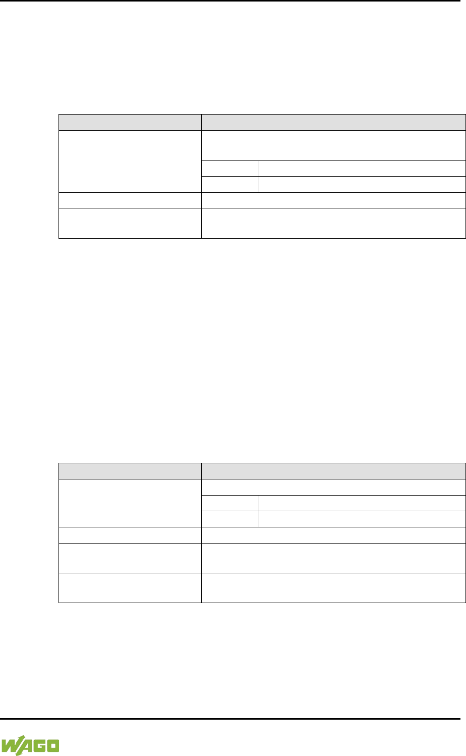
WAGO-I/O-SYSTEM 750 Commissioning 159
750-8207 PFC200 CS 2ETH RS 3G
Manual
Draft version 1.2.1 from 2017-09-13, valid from FW Version 02.06.20(09)
7.8.1.37 “Configuration of OpenVPN and IPsec” Page
The general settings for SNMP v1/v2c are shown on the “Configuration of SNMP
v1/v2c Parameters” page.
7.8.1.37.1 “OpenVPN” Group
Table 107: WBM “Configuration of OpenVPN and IPsec” Page – “OpenVPN” Group
Parameters
Explanation
Current State
The current status of the OpenVPN service is
displayed.
stopped
The service is disabled.
running
The service is enabled.
OpenVPN enabled
Enable or disable the OpenVPN service.
openvpn.config
Select an OpenVPN configuration file to be
transferred from PC to controller or vice versa.
To apply a status change, click the [Submit] button.
To select a file on the controller or PC, click the [Browse] button.
To transfer the selected file from the PC to the controller, click [Start Upload]
button.
To transfer the selected file from the controller to the PC, click [Start Download]
button.
The changes only take effect after restarting the controller. For this purpose, use
the WBM reboot function. Do not shut down the controller too early!
7.8.1.37.2 “IPsec” Group
Table 108: WBM “Configuration of OpenVPN and IPsec” Page – “IPsec” Group
Parameters
Explanation
Current State
The current status of the IPsec service is displayed.
stopped
The service is disabled.
running
The service is enabled.
IPsec enabled
Enable or disable the IPsec service.
ipsec.config
Select an IPsec configuration file to be transferred
from PC to controller or vice versa.
ipsec.secrets
Select an IPsec configuration file to be transferred
from PC to controller.
To apply a status change, click the [Submit] button.
To select a file on the controller or PC, click the [Browse] button.
To transfer the selected file to the controller, click [Start Upload] button.

160 Commissioning WAGO-I/O-SYSTEM 750
750-8207 PFC200 CS 2ETH RS 3G
Manual
Draft version 1.2.1 from 2017-09-13, valid from FW Version 02.06.20(09)
To transfer the selected file from the controller to the PC, click [Start Download]
button.
The changes only take effect after restarting the controller. For this purpose, use
the WBM reboot function. Do not shut down the controller too early!
7.8.1.37.3 “Certificate Upload” Group
Table 109: WBM “Configuration of OpenVPN and IPsec” Page – “Certificate Upload” Group
Parameters
Explanation
New Certificate
Select an certificate for transfer from a PC to the
controller.
New Private Key
Select a key for transfer from a PC to the controller.
To select a file on the PC, click the [Browse] button.
To transfer the selected file to the controller, click [Start Upload] button. The
changes will be effective immediately.
The certificates are saved in the directory “/etc/certificates/” and the keys in the
directory “/etc/certificates/keys/”.
7.8.1.37.4 “Certificate List” Group
Table 110: WBM “Configuration of OpenVPN and IPsec” Page – “Certificate List” Group
Parameters
Explanation
<certificate name>
The loaded certificates are displayed. If no
certificate has been loaded. “No certificates existing”
is displayed.
Click [Delete] to delete an entry. The changes will be effective immediately.
7.8.1.37.5 “Private Key List” Group
Table 111: WBM “Configuration of OpenVPN and IPsec” Page – “Private Key List” Group
Parameters
Explanation
<key name>
The loaded keys are displayed. If no keys has been
loaded. “No keys existing” is displayed.
Click [Delete] to delete an entry. The changes will be effective immediately.
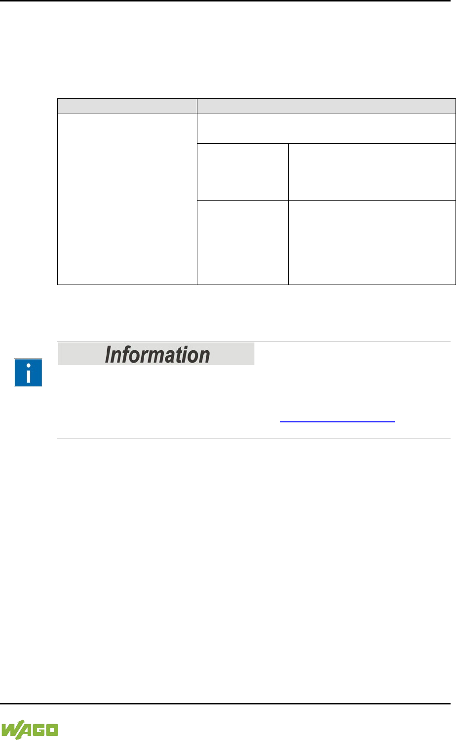
WAGO-I/O-SYSTEM 750 Commissioning 161
750-8207 PFC200 CS 2ETH RS 3G
Manual
Draft version 1.2.1 from 2017-09-13, valid from FW Version 02.06.20(09)
7.8.1.38 “Security Settings” Page
The network security settings are found on the “Security Settings” page.
7.8.1.38.1 “TLS Configuration” Group
Table 112: “Security Settings” WBM Page – “TLS Configuration” Group
Parameters
Explanation
TLS configuration
Here you can set what TLS versions and
cryptographic methods are allowed for HTTPS.
Standard
The Webserver allows TLS 1.0,
TLS 1.1 and TLS 1.2, as well as
cryptographic methods that are
no longer considered secure.
Strong
The Webserver only allows TLS
Version 1.2 and strong
algorithms.
Older software and older
operating systems may not
support TLS 1.2.
Click on [Submit] to accept the changes. The changes will be effective
immediately.
BSI Technical Guidelines TR-02102
The rules for the “Strong” setting are based on technical guidelines TR-02102 of
the German Federal Office for Information Security.
You can find the guidelines on the Internet at: https://www.bsi.bund.de >
“Publications” > “Technical Guidelines.”

162 Commissioning WAGO-I/O-SYSTEM 750
750-8207 PFC200 CS 2ETH RS 3G
Manual
Draft version 1.2.1 from 2017-09-13, valid from FW Version 02.06.20(09)
7.8.2 “Open Source Licenses” Page
The licence conditions for the open source software used for the controller are
listed in alphabetical order on the “Open Source Licenses” page.

WAGO-I/O-SYSTEM 750 Commissioning 163
750-8207 PFC200 CS 2ETH RS 3G
Manual
Draft version 1.2.1 from 2017-09-13, valid from FW Version 02.06.20(09)
7.8.3 “WAGO Licenses” Page
The licence conditions for the WAGO software used in the controller are listed on
the “WAGO Licenses” page.
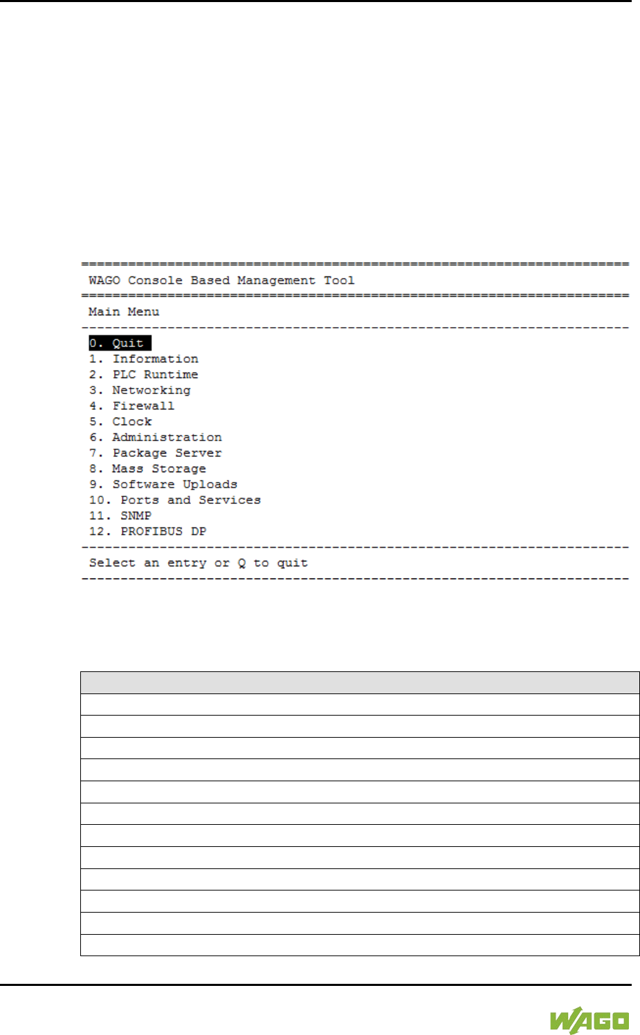
164 Commissioning WAGO-I/O-SYSTEM 750
750-8207 PFC200 CS 2ETH RS 3G
Manual
Draft version 1.2.1 from 2017-09-13, valid from FW Version 02.06.20(09)
7.8.4 Configuration using a Terminal Program (CBM)
You can use the Console-Based Management Tool (CBM) to configure the
controller via the ETHERNET interface and SSH, as well as the RS-232 interface
and Linux® console.
To establish a connection via the serial interface, set the baud rate to 115200
baud in the terminal program. The settings for data bits, stop bits and parity do
not need to be adjusted.
To launch the CBM, log in to the Linux® console and enter the command "cbm"
(case sensitive).
Figure 44: CBM main menu (example)
7.8.4.1 CBM Menu Structure Overview
Table 113: CBM Menu Structure
Menu Hierarchy
0. Quit
1. Information
0. Back to Main Menu
1. Controller Details
2. Network Details
2. PLC Runtime
0. Back to Main Menu
1. Information
2. General Configuration
3. WebVisu
3. Networking
0. Back to Main Menu

WAGO-I/O-SYSTEM 750 Commissioning 165
750-8207 PFC200 CS 2ETH RS 3G
Manual
Draft version 1.2.1 from 2017-09-13, valid from FW Version 02.06.20(09)
Table 113: CBM Menu Structure
Menu Hierarchy
1. Host-/Domain Name
2. TCP/IP
0. Back to Networking Menu
1. IP Address
2. Default Gateway
3. DNS Server
3. Ethernet
0. Back to Networking Menu
1. Switch Configuration
2. Ethernet Ports
0. Back to Ethernet Menu
1. Interface X1
2. Interface X2
4. Firewall
0. Back to Main Menu
1. General Configuration
2. MAC Address Filter
3. User Filter
5. Clock
0. Back to Main Menu
1. Date on device (local)
2. Time on device (local)
3. Time on device (UTC)
4. Clock Display Mode
5. Timezone
6. TZ-String
6. Administration
0. Back to Main Menu
1. Users
2. Create Image
3. Owner of Serial Interface
4. Reboot Controller
7. Package Server
0. Back to Main Menu
1. Firmware Backup
2. Firmware Restore
3. System Partition
8. Mass Storage
0. Back to Main Menu
1. Internal Flash (active partition)
9. Software Uploads
0. Back to Main Menu
166 Commissioning WAGO-I/O-SYSTEM 750
750-8207 PFC200 CS 2ETH RS 3G
Manual
Draft version 1.2.1 from 2017-09-13, valid from FW Version 02.06.20(09)
Table 113: CBM Menu Structure
Menu Hierarchy
1. Update Script
10. Ports and Services
0. Back to Main Menu
1. Telnet
2. FTP
3. FTPS
4. HTTP
5. HTTPS
6. NTP
7. SSH
8. TFTP
9. DHCPD
10. DNS
11. IOCHECK PORT
12. Modbus TCP
13. Modbus UDP
14. PLC Runtime Services
11. SNMP
0. Back to Main Menu
1. General SNMP Configuration
2. SNMP v1/v2c Manager Configuration
3. SNMP v1/v2c Trap Receiver Configuration
4. SNMP v3 Configuration
5. SNMP firewalling
6. Secure SNMP firewalling
Do not power cycle the controller after changing any parameters!
Some parameter changes require a controller restart for the changes to apply.
Saving changes takes time.
Do not power cycle the controller to perform a restart, i.e., changes may be lost
by shutting down the controller too soon.
Only restart the controller using the software reboot function. This ensures that
all memory operations are completed correctly and completely.
WAGO-I/O-SYSTEM 750 Commissioning 167
750-8207 PFC200 CS 2ETH RS 3G
Manual
Draft version 1.2.1 from 2017-09-13, valid from FW Version 02.06.20(09)
7.8.4.2 “Information” Menu
This menu contains other submenus with information on the controller and
network.
Table 114: “Information” Menu
Menu Item
Explanation
0. Back to …
Back to the higher-level menu
1. Controller Details
Opens a submenu with controller properties
2. Network Details
Opens a submenu with controller network and
interface properties
To make a selection, choose the appropriate menu item.
To return to the higher-level menu, press [Q].
7.8.4.2.1 “Information” > “Controller Details” Submenu
In this submenu, the controller properties are displayed.
Table 115: “Information” > “Controller Details” Submenu
Parameters
Explanation
Product Description
Controller identification
Order Number
Item number of the controller
License Information
Notification that the CODESYS runtime system is
available
Firmware Revision
Firmware status
To return to the higher-level menu, press [Q] or [Return].

168 Commissioning WAGO-I/O-SYSTEM 750
750-8207 PFC200 CS 2ETH RS 3G
Manual
Draft version 1.2.1 from 2017-09-13, valid from FW Version 02.06.20(09)
7.8.4.2.2 “Information” > “Network Details” Submenu
In this submenu, the network and interface properties of the controller are
displayed.
If the EHERNET interfaces are operated in “Switched” mode, a common table
(“X1/X2”) is displayed for both connections.
If the EHERNET interfaces are operated in “Separated” mode, an individual table
(“X1” / “X2”) is displayed for each connection.
Table 116: “Information” > “Network Details” Submenu
Parameters
Explanation
State
Status of the ETHERNET interface
(enabled/disabled)
Mac Address
MAC address identifies and addresses the controller
IP Address
Current IP address of the controller and (in brackets)
the reference type (static/bootp/dhcp)
Subnet Mask
Current subnet mask of the controller
To return to the higher-level menu, press [Q] or [Return].

WAGO-I/O-SYSTEM 750 Commissioning 169
750-8207 PFC200 CS 2ETH RS 3G
Manual
Draft version 1.2.1 from 2017-09-13, valid from FW Version 02.06.20(09)
7.8.4.3 “PLC Runtime” Menu
This menu contains other submenus with information and settings for the runtime
system.
Table 117: “PLC Runtime” Menu
Menu Item
Explanation
0. Back to …
Back to the higher-level menu
1. Information
Opens a submenu with information on the runtime
system
2. General Configuration
Opens a submenu with settings for the runtime
system
3. WebVisu
Opens a submenu with settings for the Web
visualization
To make a selection, choose the appropriate menu item.
To return to the higher-level menu, press [Q].
7.8.4.3.1 “PLC Runtime” > “Information” Submenu
This submenu contains other submenus with information on the runtime system
and PLC program.
Menu items 2 … 6 only appear if CODESYS 2 is set as the runtime system.
Table 118: “PLC Runtime” > “Information” Submenu
Menu Item
Explanation
0. Back to …
Back to the higher-level menu
1. Runtime Version
Opens a submenu to display the runtime version
2. Webserver Version
Opens a submenu to display the Webserver version
3. State
Opens a submenu to display the PLC operating
state
4. Number of Tasks
Opens a submenu to display the number of tasks in
the PLC program
5. Project Details
Opens a submenu to display the PLC program
project information
6. Tasks
Opens a submenu to display the tasks in the PLC
program
To make a selection, choose the appropriate menu item.
To return to the higher-level menu, press [Q].
170 Commissioning WAGO-I/O-SYSTEM 750
750-8207 PFC200 CS 2ETH RS 3G
Manual
Draft version 1.2.1 from 2017-09-13, valid from FW Version 02.06.20(09)
7.8.4.3.2 “Information” > “Runtime Version” Submenu
In this submenu, the runtime version is displayed.
Table 119: “PLC Runtime” > “Information” > “Runtime Version” Submenu
Parameters
Explanation
Version
The version of the currently enabled runtime system
is shown. If the runtime system is disabled, “None”
is displayed.
To return to the higher-level menu, press [Q] or [Return].
7.8.4.3.3 “Information” > “Webserver Version” Submenu
In this submenu, the Webserver version is displayed.
The submenu only appears when CODESYS 2 is enabled as the runtime system.
Table 120: “PLC Runtime” > “Information” > “Webserver Version” Submenu
Parameters
Explanation
Version
The Webserver version is displayed.
To return to the higher-level menu, press [Q] or [Return].
7.8.4.3.4 “Information” > “State” Submenu
In this submenu, the PLC operating state is displayed.
The submenu only appears when CODESYS 2 is enabled as the runtime system.
Table 121: “PLC Runtime” > “Information” > “State” Submenu
Parameters
Explanation
State
The PLC operating state is shown.
STOP
PLC program is not executed.
RUN
PLC program is executed.
To return to the higher-level menu, press [Q] or [Return].
WAGO-I/O-SYSTEM 750 Commissioning 171
750-8207 PFC200 CS 2ETH RS 3G
Manual
Draft version 1.2.1 from 2017-09-13, valid from FW Version 02.06.20(09)
7.8.4.3.5 “Information” > “Number of Tasks” Submenu
In this submenu, the number of tasks in the PLC program are displayed.
The submenu only appears when CODESYS 2 is enabled as the runtime system.
Table 122: “PLC Runtime” > “Information” > “Number of Tasks” Submenu
Parameters
Explanation
Number of Tasks
The number of tasks in the PLC program is shown.
To return to the higher-level menu, press [Q] or [Return].
7.8.4.3.6 “Information” > “Project Details” Submenu
In this submenu, project information from the PLC program is displayed.
The submenu only appears when CODESYS 2 is enabled as the runtime system
and the program is executed.
Table 123: “PLC Runtime” > “Information” > “Project Details” Submenu
Parameters
Explanation
Date
Display of project information that the programmer
entered in the PLC program (in the programming
software under Project > Project Information ...)
Descriptive text with up to 1024 characters is
displayed under “Description”.
Title
Version
Author
Description
To return to the higher-level menu, press [Q] or [Return].
7.8.4.3.7 “Information” > “Tasks” Submenu
In this submenu, tasks from the PLC program are displayed. An entry is
generated for each task.
The submenu only appears when CODESYS 2 is enabled as the runtime system.
Table 124: “PLC Runtime” > “Information” > “Tasks” Submenu
Menu Item
Explanation
0. Back to …
Back to the higher-level menu
n. Task n
Opens a submenu with information on the selected
task
To make a selection, choose the appropriate menu item.
To return to the higher-level menu, press [Q].
172 Commissioning WAGO-I/O-SYSTEM 750
750-8207 PFC200 CS 2ETH RS 3G
Manual
Draft version 1.2.1 from 2017-09-13, valid from FW Version 02.06.20(09)
7.8.4.3.8 “Tasks” > “Task n” Submenu
In this submenu, information on the selected task is displayed.
The submenu only appears when CODESYS 2 is enabled as the runtime system.
Table 125: “PLC Runtime” > “Information” > “Tasks” > “Task n” Submenu
Parameters
Explanation
Cycle count
Number of task cycles since the system start
Cycle time (µsec)
Currently measured task cycle time for the task
Cycle time min (µsec)
Minimum task cycle time for the task since the
system start
Cycle time max (µsec)
Maximum task cycle time for the task since the
system start
Cycle time avg (µsec)
Average task cycle time since the system start
Status
Task status (e.g., RUN, STOP)
Mode
Task execution mode (e.g., in cycles)
Priority
Set task priority
Interval (msec)
Set task interval
To return to the higher-level menu, press [Q] or [Return].
7.8.4.3.9 “PLC Runtime” > “General Configuration” Submenu
This submenu contains other submenus with general settings for the runtime
system.
Table 126: “PLC Runtime” > “General Configuration” Submenu
Menu Item
Explanation
0. Back to …
Back to the higher-level menu
1. PLC Runtime Version
Opens a submenu for the CODESYS runtime
system settings
2. Home Dir On SD Card
Opens a submenu for the home directory settings
To make a selection, choose the appropriate menu item.
To return to the higher-level menu, press [Q].
WAGO-I/O-SYSTEM 750 Commissioning 173
750-8207 PFC200 CS 2ETH RS 3G
Manual
Draft version 1.2.1 from 2017-09-13, valid from FW Version 02.06.20(09)
7.8.4.3.10 “General Configuration” > “PLC Runtime Version” Submenu
In this submenu, select which PLC runtime system is enabled.
Table 127: “PLC Runtime” > “General Configuration” > “PLC Runtime Version” Submenu
Menu Item
Explanation
0. Back to …
Back to the higher-level menu
1. None
No runtime system is enabled.
2. CODESYS 2
The CODESYS 2 runtime system is enabled.
3. e!RUNTIME
The e!RUNTIME runtime system is enabled.
All data is deleted when switching the runtime system!
The runtime system’s home directory is completely deleted when switching the
runtime system!
To make a selection, choose the appropriate menu item.
To return to the higher-level menu, press [Q].
7.8.4.3.11 “General Configuration” > “Home Dir On SD Card” Submenu
In this submenu, define if the home directory for the runtime system should be
moved to the memory card.
Table 128: “PLC Runtime” > “General Configuration” > “Home Dir On SD Card” Submenu
Menu Item
Explanation
0. Back to …
Back to the higher-level menu
1. Enable
The home directory is moved to the memory card.
2. Disable
The home directory is stored in the internal memory.
Insert a memory card before switching the home directory!
When moving the home directory to the memory card, insert a memory card
formatted to support file system. Only the first partition of a memory card can be
accessed at /media/sd and can be used as the home directory.
Perform a reset before switching the home directory!
Stop IEC-61131 applications in use before switching the home directory of the
runtime system.
Restore the device to its initial state using the “Reset” function. Any boot project
is deleted.
To make a selection, choose the appropriate menu item.
To return to the higher-level menu, press [Q].

174 Commissioning WAGO-I/O-SYSTEM 750
750-8207 PFC200 CS 2ETH RS 3G
Manual
Draft version 1.2.1 from 2017-09-13, valid from FW Version 02.06.20(09)
7.8.4.3.12 “PLC Runtime” > “WebVisu” Submenu
This submenu contains information and settings for the Web visualization.
Table 129: “PLC Runtime” > “WebVisu” Submenu
Menu Item
Submenu Item / Explanation
0. Back to …
Back to the higher-level menu
1. CODESYS 2 Webserver
State
The status of the CODESYS 2 Webserver is
displayed.
2. e!RUNTIME Webserver
State
The status of the e!RUNTIME Webserver is
displayed.
3. Default Webserver
Choose here whether the Web-based Management
or web visualization of the runtime system should be
displayed when only entering the IP address of the
controller.
0. Back to …
Back to the higher-level menu
1. Web-based
Managem
ent
The Web-based Management is
displayed.
2. CODESYS
WebVisu
The web visualization of the runtime
system is displayed.
To make a selection, choose the appropriate menu item.
To return to the higher-level menu, press [Q].

WAGO-I/O-SYSTEM 750 Commissioning 175
750-8207 PFC200 CS 2ETH RS 3G
Manual
Draft version 1.2.1 from 2017-09-13, valid from FW Version 02.06.20(09)
7.8.4.4 “Networking” Menu
This menu contains other submenus with settings for the network configuration.
Table 130: “Networking” Menu
Parameters
Explanation
0. Back to …
Back to the higher-level menu
1. Host/Domain Name
Opens a submenu with setting options for the
general TCP/IP parameters
2. TCP/IP
Opens a submenu with TCP/IP settings for the
ETHERNET interfaces
3. Ethernet
Opens a submenu with settings for the ETHERNET
configuration
To make a selection, choose the appropriate menu item.
To return to the higher-level menu, press [Q].
7.8.4.4.1 “Networking” > “Host/Domain Name” Submenu
This submenu contains the “Hostname” and “Domain Name” submenu with
setting options for the general TCP/IP parameters.
Table 131: “Networking” > “Host/Domain Name” Submenu
Parameters
Explanation
0. Back to …
Back to the higher-level menu
1. Hostname
Opens a submenu with the hostname settings
In addition to the menu item, the configured and
current hostname are displayed.
2. Domain Name
Opens a submenu hostname settings
In addition to the menu item, the configured and
current domain name are displayed.
To make a selection, choose the appropriate menu item.
To return to the higher-level menu, press [Q].

176 Commissioning WAGO-I/O-SYSTEM 750
750-8207 PFC200 CS 2ETH RS 3G
Manual
Draft version 1.2.1 from 2017-09-13, valid from FW Version 02.06.20(09)
7.8.4.4.2 “Host/Domain Name” > “Hostname” Submenu
In this submenu, you can set the hostname of the controller.
Table 132: “Networking” > “Hostname” Submenu
Parameters
Explanation
Enter new Hostname
Enter here the hostname of the controller to be used
if the network interface is changed to a static IP
address or if no hostname is transmitted with a
DHCP response.
Click [<OK>] to apply the entry.
Click [<Abort>] to discard the entry.
7.8.4.4.3 “Host/Domain Name” > “Domain Name” Submenu
In this submenu, you can set the domain name of the controller.
Table 133: “Networking” > “Host/Domain Name” > “Domain Name” Submenu
Parameters
Explanation
Enter new Domain Name
Enter the domain name.
The default entry is “localdomain.lan”.
Click [<OK>] to apply the entry.
Click [<Abort>] to discard the entry.
7.8.4.4.4 “Networking” > “TCP/IP” Submenu
This submenu contains other submenus with the TCP/IP settings for the
ETHERNET interfaces.
Table 134: “Networking” > “TCP/IP” Submenu
Menu Item
Explanation
0. Back to …
Back to the higher-level menu
1. IP Address
Opens a submenu with settings for the IP
address(es)
2. Default Gateway
Opens a submenu with settings for the default
gateway
3. DNS Server
Opens a submenu with settings for the DNS
server(s)
To make a selection, choose the appropriate menu item.
To return to the higher-level menu, press [Q].
WAGO-I/O-SYSTEM 750 Commissioning 177
750-8207 PFC200 CS 2ETH RS 3G
Manual
Draft version 1.2.1 from 2017-09-13, valid from FW Version 02.06.20(09)
7.8.4.4.5 “TCP/IP” > “IP Address” Submenu
This submenu contains other submenus with settings for the ETHERNET
interfaces.
The submenu only appears if the controller is operated in “Separated” mode.
If the controller is operated in “Switched” mode, then the “IP Address” > “X1”
submenu is displayed directly.
Table 135: “Networking” > “IP Address” Submenu
Menu Item
Explanation
0. Back to …
Back to the higher-level menu
1. X1
Opens a submenu with settings for the X1 interface
2. X2
Opens a submenu with settings for the X2 interface
To make a selection, choose the appropriate menu item.
To return to the higher-level menu, press [Q].
7.8.4.4.6 “IP Address” > “Xn“ Submenu
This submenu contains the settings for the selected interface.
Table 136: “Networking” > “TCP/IP” > “IP Address” Submenu > “Xn”
Menu Item
Submenu Item / Explanation
0. Back to …
Back to the higher-level menu
1. Type of IP Address
Configuration
Select a static or dynamic IP address.
0. Back to …
Back to the higher-level menu
1. Static IP
Static IP addressing
When selecting static addressing, the
IP address and subnet mask are then
retrieved.
2. DHCP
Dynamic IP addressing
3. BootP
Dynamic IP addressing
2. IP Address
Enter here a static IP address.
3. Subnet Mask
Enter the subnet mask.
To make a selection, choose the appropriate menu item.
To return to the higher-level menu, press [Q].
Click [<OK>] to apply the entry.
Click [<Abort>] to discard the entry.
178 Commissioning WAGO-I/O-SYSTEM 750
750-8207 PFC200 CS 2ETH RS 3G
Manual
Draft version 1.2.1 from 2017-09-13, valid from FW Version 02.06.20(09)
7.8.4.4.7 “TCP/IP” > “Default Gateway” Submenu
This submenu contains other submenus with settings for the default gateway.
Table 137: “Networking” > “TCP/IP” > “Default Gateway” Submenu
Menu Item
Explanation
0. Back to …
Back to the higher-level menu
1. Default Gateway 1
Opens a submenu with settings for default gateway
1
In addition to the menu item, the current status of
the gateway is displayed.
2. Default Gateway 2
Opens a submenu with settings for default gateway
2
In addition to the menu item, the current status of
the gateway is displayed.
To make a selection, choose the appropriate menu item.
To return to the higher-level menu, press [Q].
7.8.4.4.8 “Default Gateway” > “Default Gateway n” Submenu
This submenu contains the settings for the selected gateway.
Table 138: “Networking” > “TCP/IP” > “Default Gateway” > “Default Gateway n” Submenu
Menu Item
Submenu Item / Explanation
0. Back to …
Back to the higher-level menu
1. State
Set here whether the selected default gateway is to
be used.
0. Back to …
Back to the higher-level menu
1. Disabled
The default gateway is not used.
2. Enabled
The default gateway is used.
2. Gateway IP Address
Enter the address of the default gateway.
3. Gateway Metric
Set here a number as the metric.
The default value for the metric is 20, the lowest
value is 0, the highest value is 4.294.967.295.
To make a selection, choose the appropriate menu item.
To return to the higher-level menu, press [Q].
Click [<OK>] to apply the entry.
Click [<Abort>] to discard the entry.
WAGO-I/O-SYSTEM 750 Commissioning 179
750-8207 PFC200 CS 2ETH RS 3G
Manual
Draft version 1.2.1 from 2017-09-13, valid from FW Version 02.06.20(09)
7.8.4.4.9 “TCP/IP” > “DNS Server” Submenu
This submenu contains the settings for the DNS server.
Table 139: “Networking” > “TCP/IP” > “DNS Server” Submenu
Menu Item
Submenu Item / Explanation
0. Back to …
Back to the higher-level menu
n. DNS Server n
The addresses of the defined DNS servers are
displayed. Other submenus are available for the
server entered.
0. Back to …
Back to the higher-level menu
1. Edit
You can change the selected DNS
server address.
2. Delete
You can delete the selected DNS
server address.
(n+1). Add new DNS
Server
Add additional DNS server addresses.
You can enter 10 addresses.
To make a selection, choose the appropriate menu item.
To return to the higher-level menu, press [Q].
Click [<OK>] to apply the entry.
Click [<Abort>] to discard the entry.
7.8.4.4.10 “Networking” > “Ethernet” Submenu
This submenu contains other submenus with settings for the ETHERNET
configuration.
Table 140: “Networking” > “Ethernet” Submenu
Menu Item
Explanation
0. Back to …
Back to the higher-level menu
1. Switch Configuration
Opens a submenu with settings for the IP
address(es)
2. Ethernet Ports
Opens a submenu with settings for the ETHERNET
interfaces
To make a selection, choose the appropriate menu item.
To return to the higher-level menu, press [Q].
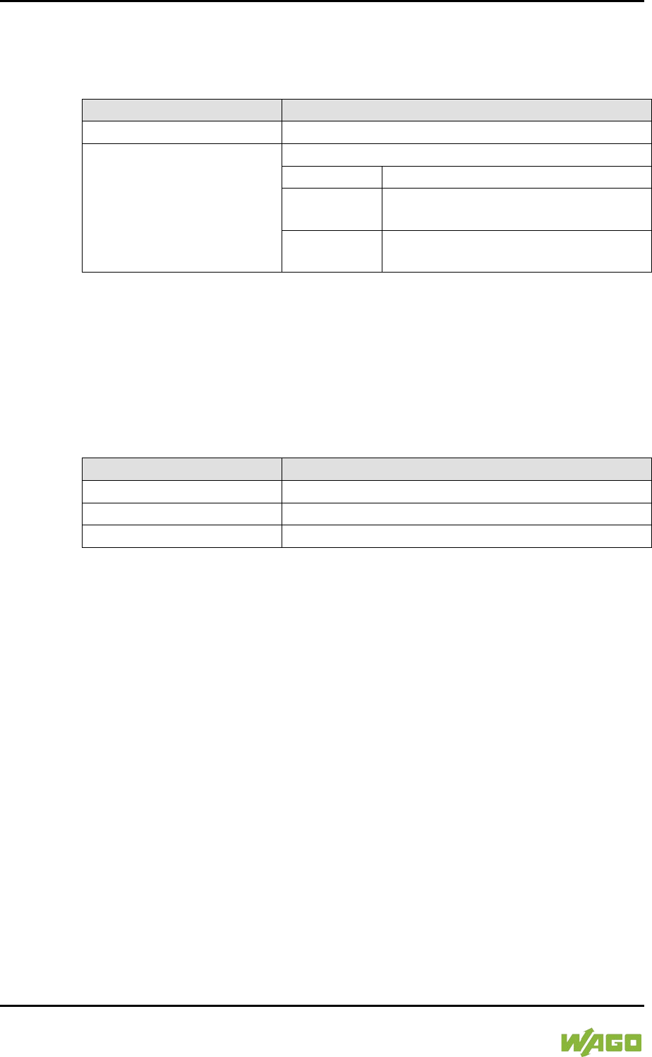
180 Commissioning WAGO-I/O-SYSTEM 750
750-8207 PFC200 CS 2ETH RS 3G
Manual
Draft version 1.2.1 from 2017-09-13, valid from FW Version 02.06.20(09)
7.8.4.4.11 “Ethernet” > “Switch Configuration” Submenu
This submenu contains the settings for the Switch configuration.
Table 141: “Networking” > “Ethernet” > “Switch Configuration” Submenu
Submenu
Submenu Item / Explanation
0. Back to …
Back to the higher-level menu
1. Network interfaces
Enable or disable the switch.
0. Back to …
Back to the higher-level menu
1. Separated
Each interface is operated with its
own IP address.
2. Switched
Both interfaces are operated with one
IP address.
To make a selection, choose the appropriate menu item.
To return to the higher-level menu, press [Q].
7.8.4.4.12 “Ethernet” > “Ethernet Ports” Submenu
This submenu contains other submenus with settings for the ETHERNET
interfaces.
Table 142: “Networking” > “Ethernet” > “Ethernet Ports” Submenu
Menu Item
Explanation
0. Back to …
Back to the higher-level menu
1. Interface X1
Opens a submenu with settings for the X1 interface
2. Interface X2
Opens a submenu with settings for the X2 interface
To make a selection, choose the appropriate menu item.
To return to the higher-level menu, press [Q].

WAGO-I/O-SYSTEM 750 Commissioning 181
750-8207 PFC200 CS 2ETH RS 3G
Manual
Draft version 1.2.1 from 2017-09-13, valid from FW Version 02.06.20(09)
7.8.4.4.13 “Ethernet Ports” > “Interface Xn” Submenu
This submenu contains the settings for the selected ETHERNET interface.
Table 143: “Networking” > “Ethernet” > “Ethernet Ports” > “Interface Xn” Submenu
Submenu
Submenu Item / Explanation
0. Back to …
Back to the higher-level menu
1. Port
Set here whether the selected port is to be used.
0. Back to …
Back to the higher-level menu
1. Disabled
The port is not used.
2. Enabled
The port is used.
2. Autonegotiation
Set here whether the Autonegotiation function is
enabled for the selected port.
0. Back to …
Back to the higher-level menu
1. Disabled
Autonegotiation is disabled.
2. Enabled
Autonegotiation is enabled.
To make a selection, choose the appropriate menu item.
To return to the higher-level menu, press [Q].

182 Commissioning WAGO-I/O-SYSTEM 750
750-8207 PFC200 CS 2ETH RS 3G
Manual
Draft version 1.2.1 from 2017-09-13, valid from FW Version 02.06.20(09)
7.8.4.5 “Firewall” Menu
This menu contains other submenus for the firewall functionality settings.
Table 144: “Firewall” Menu
Menu Item
Explanation
0. Back to …
Back to the higher-level menu
1. General Configuration
Opens a submenu with general firewall settings
2. MAC Address Filter
Opens a submenu with MAC address filter settings
3. User Filter
Opens a submenu with user filter settings
To make a selection, choose the appropriate menu item.
To return to the higher-level menu, press [Q].

WAGO-I/O-SYSTEM 750 Commissioning 183
750-8207 PFC200 CS 2ETH RS 3G
Manual
Draft version 1.2.1 from 2017-09-13, valid from FW Version 02.06.20(09)
7.8.4.5.1 “Firewall” > “General Configuration” Submenu
This submenu contains the general settings for the firewall.
Table 145: “Firewall” > “General Configuration” Submenu
Menu Item
Submenu Item / Explanation
0. Back to …
Back to the higher-level menu
1. Firewall enabled entirely
Enables/disables the complete functionality of the
firewall.
0. Back to …
Back to the higher-level menu
1. Enable
Firewall is enabled.
2. Disable
Firewall is disabled.
2. ICMP echo broadcast
protection
Enable or disable the “ICMP echo broadcast”
protection.
0. Back to …
Back to the higher-level menu
1. Enable
“ICMP echo broadcast” protection is
enabled.
2. Disable
“ICMP echo broadcast” protection is
disabled.
3. Max UDP connections
per second
You can specify the maximum number of UDP
connections per second.
“0” = “Disabled”
4. Max TCP connections
per second
You can specify the maximum number of TCP
connections per second.
“0” = “Disabled”
5. Interface WAN
Opens a submenu with firewall settings on the IP
level for the selected interface
6. Interface VPN
7. Interface X1
8. Interface X2
To make a selection, choose the appropriate menu item.
To return to the higher-level menu, press [Q].
Click [<OK>] to apply the entry.
Click [<Abort>] to discard the entry.

184 Commissioning WAGO-I/O-SYSTEM 750
750-8207 PFC200 CS 2ETH RS 3G
Manual
Draft version 1.2.1 from 2017-09-13, valid from FW Version 02.06.20(09)
7.8.4.5.2 “General Configuration” > “Interface xxx” Submenu
This submenu contains the firewall settings on the IP level for the selected
interface.
Table 146: “Firewall” > “General Configuration” > “Interface xxx” Submenu
Menu Item
Submenu Item / Explanation
0. Back to …
Back to the higher-level menu
1. Interface state
Enable or disable the firewall for the selected
interface.
0. Back to …
Back to the higher-level menu
1. Open
The firewall for the selected interface
is disabled.
2. Filtered
The firewall for the selected interface
is enabled.
2. ICMP Policy
Enable or disable the “ICMP echo” protection for the
respective interface.
0. Back to …
Back to the higher-level menu
1. Accept
The “ICMP echo” protection is
disabled.
2. Drop
The “ICMP echo” protection is
enabled.
3. ICMP Limit
You can specify the maximum number of “ICMP
pings” per second.
“0” = “Disabled”
4. ICMP Burst
You can specify the maximum number of “ICMP
echo bursts” per second.
“0” = “Disabled”
5. Telnet
Enable or disable the firewall for the respective
service.
The services themselves must be enabled or
disabled separately on the “Ports and Services”
page.
6. FTP
7. FTPS
8. HTTP
9. HTTPS
10. I/O-CHECK
11. PLC Runtime
12. PLC WebVisu –
direct link (port 8080)
13. SSH
14. TFTP
15. BootP/DHCP
16. DNS
17. MODBUS TCP
18. MODBUS UDP
19. SNMP
To make a selection, choose the appropriate menu item.
To return to the higher-level menu, press [Q].

WAGO-I/O-SYSTEM 750 Commissioning 185
750-8207 PFC200 CS 2ETH RS 3G
Manual
Draft version 1.2.1 from 2017-09-13, valid from FW Version 02.06.20(09)
Click [<OK>] to apply the entry.
Click [<Abort>] to discard the entry.
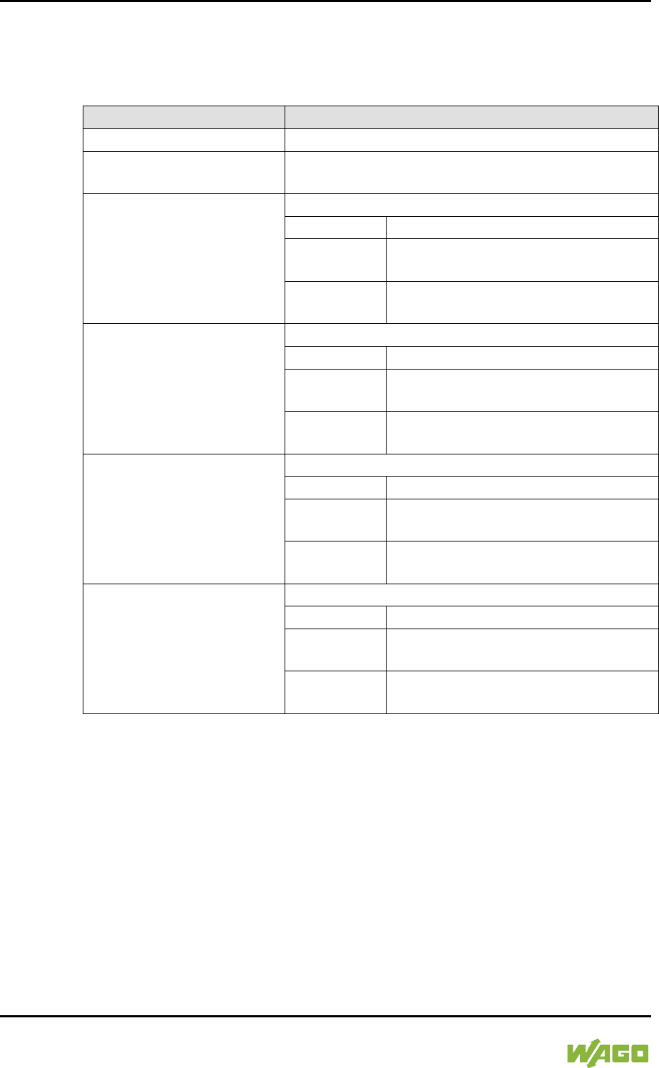
186 Commissioning WAGO-I/O-SYSTEM 750
750-8207 PFC200 CS 2ETH RS 3G
Manual
Draft version 1.2.1 from 2017-09-13, valid from FW Version 02.06.20(09)
7.8.4.5.3 “Firewall” > “MAC Address Filter” Submenu
This submenu contains the settings for the MAC address filter.
Table 147: “Firewall” > “MAC Address Filter” Submenu
Menu Item
Submenu Item / Explanation
0. Back to …
Back to the higher-level menu
1. MAC address filter
whitelist
Opens a submenu to edit the MAC address filter
whitelist
2. MAC address filter state
VPN
Enable or disable the firewall for the VPN interface.
0. Back to …
Back to the higher-level menu
1. Open
The firewall for the VPN interface is
disabled.
2. Filtered
The firewall for the VPN interface is
enabled.
3. MAC address filter state
WAN
Enable or disable the firewall for the WAN interface.
0. Back to …
Back to the higher-level menu
1. Open
The firewall for the WAN interface is
disabled.
2. Filtered
The firewall for the WAN interface is
enabled.
4. MAC address filter state
X1
Enable or disable the firewall for the X1 interface.
0. Back to …
Back to the higher-level menu
1. Open
The firewall for the X1 interface is
disabled.
2. Filtered
The firewall for the X1 interface is
enabled.
5. MAC address filter state
X2
Enable or disable the firewall for the X2 interface.
0. Back to …
Back to the higher-level menu
1. Open
The firewall for the X2 interface is
disabled.
2. Filtered
The firewall for the X2 interface is
enabled.
To make a selection, choose the appropriate menu item.
To return to the higher-level menu, press [Q].

WAGO-I/O-SYSTEM 750 Commissioning 187
750-8207 PFC200 CS 2ETH RS 3G
Manual
Draft version 1.2.1 from 2017-09-13, valid from FW Version 02.06.20(09)
7.8.4.5.4 “MAC Address Filter” > “MAC address filter whitelist” Submenu
This submenu displays all available filter entries.
Table 148: “Firewall” > “MAC Address Filter” > “MAC address filter whitelist” Submenu
Menu Item
Explanation
0. Back to …
Back to the higher-level menu
1. Add new
Opens a submenu to add a new filter entry
You can enter 10 filters.
2. Previous page
Displays the previous page of the list (if more than
one page is filled)
3. Next Page
Displays the next page of the list (if more than one
page is filled)
(n + 3.) No (n):
Opens a submenu to edit an existing filter entry
To make a selection, choose the appropriate menu item.
To return to the higher-level menu, press [Q].
7.8.4.5.5 “MAC address filter whitelist” > “Add new / No (n)” Submenu
In this submenu, you can create, change or delete filter entries.
Table 149: “Firewall” > “MAC Address Filter” > “MAC address filter whitelist” > “Add new / No (n)”
Submenu
Menu Item
Submenu Item / Explanation
0. Back to …
Back to the higher-level menu
1. MAC address
Enter the MAC address.
2. MAC mask
Enter the MAC mask.
3. Filter state
Enable or disable the filter.
0. Back to …
Back to the higher-level menu
1. on
The filter is enabled.
2. off
The filter is disabled.
4. accept
To apply the changes for the selected filter entry,
choose this menu item.
5. delete
To delete the selected filter entry, choose this menu
item.
To make a selection, choose the appropriate menu item.
To return to the higher-level menu, press [Q].
Click [<OK>] to apply the entry.
Click [<Abort>] to discard the entry.

188 Commissioning WAGO-I/O-SYSTEM 750
750-8207 PFC200 CS 2ETH RS 3G
Manual
Draft version 1.2.1 from 2017-09-13, valid from FW Version 02.06.20(09)
7.8.4.5.6 “Firewall” > “User Filter” Submenu
This submenu displays all available filter entries.
Table 150: “Firewall” > “User Filter” Submenu
Menu Item
Explanation
0. Back to …
Back to the higher-level menu
1. Add new
Opens a submenu to add a new filter entry
2. Previous page
Displays the previous page of the list (if more than
one page is filled)
3. Next Page
Displays the next page of the list (if more than one
page is filled)
(n + 3.) No (n):
Opens a submenu to edit an existing filter entry
To make a selection, choose the appropriate menu item.
To return to the higher-level menu, press [Q].

WAGO-I/O-SYSTEM 750 Commissioning 189
750-8207 PFC200 CS 2ETH RS 3G
Manual
Draft version 1.2.1 from 2017-09-13, valid from FW Version 02.06.20(09)
7.8.4.5.7 “User Filter” > “Add New / No (n)” Submenu
In this submenu, you can create, change or delete filter entries.
Table 151: “Firewall” > “User Filter” > “Add New / No (n)” Submenu
Menu Item
Submenu Item / Explanation
0. Back to …
Back to the higher-level menu
1. Source IP address
Enter the source IP address.
2. Source netmask
Enter the source network mask.
3. Source port
Enter the source port number.
4. Destination IP address
Enter the destination IP address.
5. Destination netmask
Enter here the destination netmask.
6. Destination port
Enter the destination port number.
7. protocol
Select the permitted protocols.
0. Back to …
Back to the higher-level menu
1. tcp
The TCP protocol is permitted.
2. udp
The UDP protocol is permitted.
3. tcp & udp
Both protocols are permitted.
8. interface
Select the permitted interfaces.
0. Back to …
Back to the higher-level menu
1. all
All interfaces are permitted.
2. VPN
The VPN interface is permitted.
3. WAN
The WAN interface is permitted.
4. X1
The X1 interface is permitted.
5. X2
The X2 interface is permitted.
9. state
Enable or disable the filter.
0. Back to …
Back to the higher-level menu
1. on
The filter is enabled.
2. off
The filter is disabled.
10. accept
To apply the changes for the selected filter entry,
choose this menu item.
11. delete
To delete the selected filter entry, choose this menu
item.
To make a selection, choose the appropriate menu item.
To return to the higher-level menu, press [Q].
Click [<OK>] to apply the entry.
Click [<Abort>] to discard the entry.
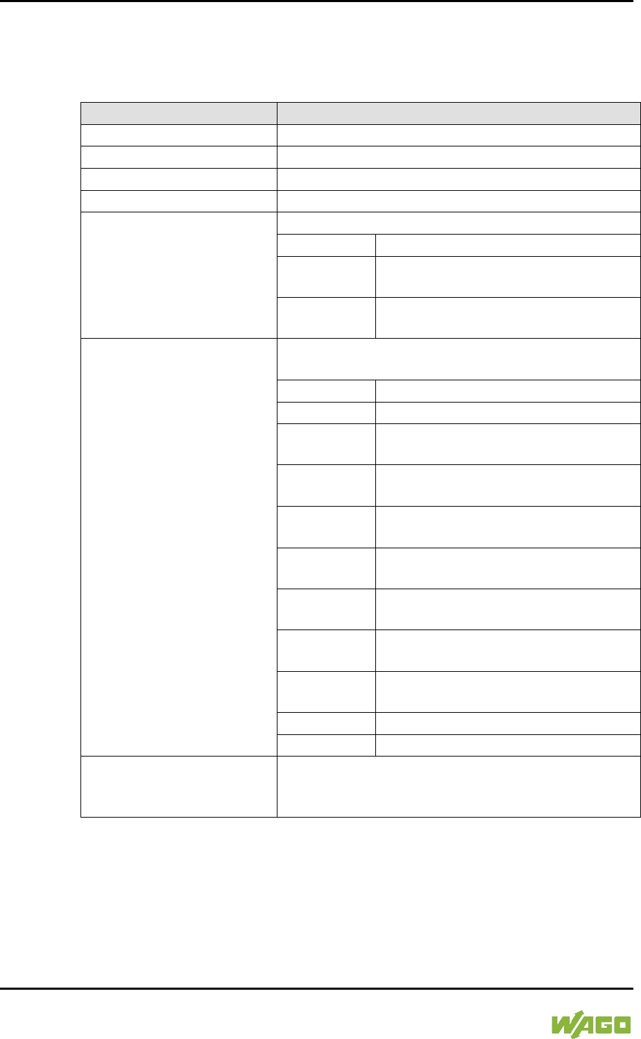
190 Commissioning WAGO-I/O-SYSTEM 750
750-8207 PFC200 CS 2ETH RS 3G
Manual
Draft version 1.2.1 from 2017-09-13, valid from FW Version 02.06.20(09)
7.8.4.6 “Clock” Menu
This menu contains other submenus for the date and time settings.
Table 152: “Clock” Menu
Menu Item
Submenu Item / Explanation
0. Back to …
Back to the higher-level menu
1. Date on device (local)
Set date.
2. Time on device (local)
Set local time.
3. Time on device (UTC)
Set GMT time.
4. Clock Display Mode
Select the display format for the time.
0. Back to …
Back to the higher-level menu
1. 24 hours
The time is displayed in 24-hour
format.
2. 12 hours
The time is displayed in 12-hour
format.
5. Timezone
Specify the appropriate time zone for your location.
Basic setting:
0. Back to …
Back to the higher-level menu
1. AST/ADT
“Atlantic Standard Time,” Halifax
2. EST/EDT
“Eastern Standard Time,” New York,
Toronto
3. CST/CDT
“Central Standard Time,” Chicago,
Winnipeg
4. MST/
MDT
“Mountain Standard Time,” Denver,
Edmonton
5. PST/PDT
“Pacific Standard Time”, Los Angeles,
Whitehouse
6. GMT/BST
Greenwich Mean Time,“ GB, P, IRL,
IS, …
7. CET/
CEST
“Central European Time,” B, DK, D,
F, I, CRO, NL, …
8. EET/
EEST
“East European Time,” BUL, FI, GR,
TR, …
9. CST
“China Standard Time”
10. JST
“Japan/Korea Standard Time”
6. TZ String
Enter the name of your time zone or country and
town if the time zone is not available for selection
using the “Timezone” parameter.
To make a selection, choose the appropriate menu item.
To return to the higher-level menu, press [Q].
Click [<OK>] to apply the entry.
Click [<Abort>] to discard the entry.
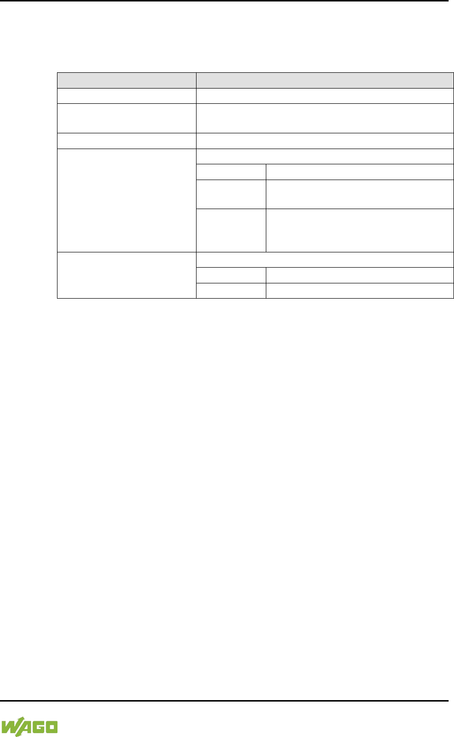
WAGO-I/O-SYSTEM 750 Commissioning 191
750-8207 PFC200 CS 2ETH RS 3G
Manual
Draft version 1.2.1 from 2017-09-13, valid from FW Version 02.06.20(09)
7.8.4.7 “Administration” Menu
This menu contains settings for controller administration.
Table 153: “Administration” Menu
Menu Item
Submenu Item / Explanation
0. Back to …
Back to the higher-level menu
1. Users
Opens a submenu with settings for the user
passwords
2. Create Image
Opens a submenu for creating a bootable image
3. Owner of Serial Interface
Select the serial interface assignment.
0. Back to …
Back to the higher-level menu
1. Linux
Console
The serial interface is assigned to the
Linux
®
console.
2. Un-
assigned
The serial interface is not assigned
and is available for applications or
CODESYS.
4. Reboot Controller
Restart the controller following a security challenge.
0. Back to …
Back to the higher-level menu
1. Reboot
Restarts the controller
To make a selection, choose the appropriate menu item.
To return to the higher-level menu, press [Q].

192 Commissioning WAGO-I/O-SYSTEM 750
750-8207 PFC200 CS 2ETH RS 3G
Manual
Draft version 1.2.1 from 2017-09-13, valid from FW Version 02.06.20(09)
7.8.4.7.1 “Administration” > “Create Image” Submenu
This submenu contains the selection for creating the image.
In addition to the menu item for the enabled storage medium, the current status is
displayed.
Table 154: “Administration” > “Create Image” Submenu
Menu Item
Explanation
0. Back to …
Back to the higher-level menu
1. SD Card
To create an image on the memory card, select this
menu item. Enter the reserved memory size in
another step.
This menu item only appears if the memory card is
inserted.
2. Internal Flash
To create an image on the internal memory, select
this menu item.
To make a selection, choose the appropriate menu item.
To return to the higher-level menu, press [Q].
Click [<OK>] to apply the entry.
Click [<Abort>] to discard the entry.
7.8.4.7.2 “Administration” > “Users” Submenu
This submenu contains settings for the user passwords.
Table 155: “Administration” > “Users” Submenu
Menu Item
Explanation
0. Back to …
Back to the higher-level menu
1. user
Enter a new password for the “user” user.
2. admin
Enter a new password for the “admin” user.
To make a selection, choose the appropriate menu item.
To return to the higher-level menu, press [Q].
Click [<OK>] to apply the entry.
Click [<Abort>] to discard the entry.

WAGO-I/O-SYSTEM 750 Commissioning 193
750-8207 PFC200 CS 2ETH RS 3G
Manual
Draft version 1.2.1 from 2017-09-13, valid from FW Version 02.06.20(09)
7.8.4.8 “Package Server” Menu
This menu contains other submenus with functions for firmware backup and
restore, as well as information and setting options for the current system partition.
Table 156: “Package Server” Menu
Menu Item
Explanation
0. Back to …
Back to the higher-level menu
1. Firmware Backup
Opens a submenu with functions for the firmware
backup
2. Firmware Restore
Opens a submenu with functions for the firmware
restore
3. System Partition
Opens a submenu with information and setting
options for the current system partition
To make a selection, choose the appropriate menu item.
To return to the higher-level menu, press [Q].
7.8.4.8.1 “Package Server” > “Firmware Backup” Submenu
This submenu contains a selection option for the data to be saved.
The submenu only appears if a memory card is inserted that does not contain a
bootable system. Otherwise, a message is displayed.
Table 157: “Package Server” > “Firmware Backup” Menu
Menu Item
Explanation
0. Back to …
Back to the higher-level menu
1. All
All data is saved.
2. PLC Runtime project
The PLC runtime project is saved.
3. Settings
The controller settings are saved.
4. System
The controller operating system is saved.
To make a selection, choose the appropriate menu item.
To return to the higher-level menu, press [Q].
You are taken to the following submenu after making the selection.

194 Commissioning WAGO-I/O-SYSTEM 750
750-8207 PFC200 CS 2ETH RS 3G
Manual
Draft version 1.2.1 from 2017-09-13, valid from FW Version 02.06.20(09)
7.8.4.8.2 “Firmware Backup” > “Auto Update Feature” Submenu
This submenu contains a setting option for the Auto Update function.
The submenu only appears if the data for the firmware backup has been
selected.
Table 158: “Package Server” > “Firmware Backup” > “Auto Update Feature” Menu
Menu Item
Explanation
0. Back to …
Back to the higher-level menu
1. No
The Auto Update function is OFF for the selected
data.
2. Yes
The Auto Update function is ON for the selected
data.
To make a selection, choose the appropriate menu item.
To return to the higher-level menu, press [Q].
You are taken to the following submenu after making the selection.
7.8.4.8.3 “Firmware Backup” > “Destination” Submenu
This submenu contains a selection option for the backup destination drive.
Table 159: “Package Server” > “Firmware Backup” > “Auto Update Feature” Menu
Menu Item
Explanation
0. Back to …
Back to the higher-level menu
1. SD Card
The selected data is copied to the memory card.
To make a selection, choose the appropriate menu item.
To return to the higher-level menu, press [Q].
The copy progress is displayed during the backup process.

WAGO-I/O-SYSTEM 750 Commissioning 195
750-8207 PFC200 CS 2ETH RS 3G
Manual
Draft version 1.2.1 from 2017-09-13, valid from FW Version 02.06.20(09)
7.8.4.8.4 “Package Server” > “Firmware Restore” Submenu
This submenu contains a selection option for the restore source drive.
In addition to the enabled partition, the current status is displayed.
Table 160: “Package Server” > “Firmware Restore” Menu
Menu Item
Explanation
0. Back to …
Back to the higher-level menu
1. SD Card
The data is copied from the memory card.
2. Internal Flash
The data is copied from the internal memory.
To make a selection, choose the appropriate menu item.
To return to the higher-level menu, press [Q].
You are taken to the following submenu after making the selection.
7.8.4.8.5 “Firmware Restore” > “Select Package” Submenu
This submenu contains a selection option for the data to be restored.
Table 161: “Package Server” > “Firmware Restore” > “Select Package” Menu
Menu Item
Explanation
0. Back to …
Back to the higher-level menu
1. PLC Runtime project
The PLC runtime project is loaded.
2. Settings
The controller settings are loaded.
3. System
The controller operating system is loaded.
4. System + Setting
The controller operating system and settings are
loaded.
5. All
All data is loaded.
To make a selection, choose the appropriate menu item.
To return to the higher-level menu, press [Q].
The copy progress is displayed during the restore process.

196 Commissioning WAGO-I/O-SYSTEM 750
750-8207 PFC200 CS 2ETH RS 3G
Manual
Draft version 1.2.1 from 2017-09-13, valid from FW Version 02.06.20(09)
7.8.4.8.6 “Package Server” > “System Partition” Submenu
This submenu contains information and setting options for the current system
partition.
Table 162: “Package Server” > “System Partition” Submenu
Menu Item
Explanation
0. Back to …
Back to the higher-level menu
1. Current active partition
The partition currently in use is displayed.
2. Set inactive NAND
partition active
Select this menu item to start the system from a
different partition at the next controller reboot.
To make a selection, choose the appropriate menu item.
To return to the higher-level menu, press [Q].

WAGO-I/O-SYSTEM 750 Commissioning 197
750-8207 PFC200 CS 2ETH RS 3G
Manual
Draft version 1.2.1 from 2017-09-13, valid from FW Version 02.06.20(09)
7.8.4.9 “Mass Storage” Menu
This menu contains information on the internal flash memory and, if inserted, on
the external memory card.
In addition to the menu item, the status is displayed for the enabled partition.
Table 163: “Mass Storage” Menu
Parameters
Explanation
0. Back to …
Back to the higher-level menu
1. SD Card
Opens a submenu with information on the memory
card and its formatting
This menu item only appears if a memory card is
inserted in the controller.
2. Internal Flash
Opens a submenu with information on the internal
flash memory
To make a selection, choose the appropriate menu item.
To return to the higher-level menu, press [Q].
7.8.4.9.1 “Mass Storage” > “SD Card” Submenu
This submenu contains information on the external memory card and its
formatting.
This submenu only appears if a memory card is inserted in the controller.
Table 164: “Mass Storage” > “SD Card” Menu
Parameters
Explanation
0. Back to …
Back to the higher-level menu
1. Show information
Displays information on the memory card
2. FAT format medium
To format the memory card in FAT format, select
this menu item. Then specify a volume name.
To make a selection, choose the appropriate menu item.
To return to the higher-level menu, press [Q].
Click [<OK>] to apply the entry.
Click [<Abort>] to discard the entry.

198 Commissioning WAGO-I/O-SYSTEM 750
750-8207 PFC200 CS 2ETH RS 3G
Manual
Draft version 1.2.1 from 2017-09-13, valid from FW Version 02.06.20(09)
7.8.4.10 “Software Uploads” Menu
This menu contains choices and settings for the device update.
You can select fieldbus software, program licenses and update scripts, for
example, for transfer from a PC to the controller.
You can also enable transmitted packages or delete from the controller.

WAGO-I/O-SYSTEM 750 Commissioning 199
750-8207 PFC200 CS 2ETH RS 3G
Manual
Draft version 1.2.1 from 2017-09-13, valid from FW Version 02.06.20(09)
7.8.4.11 “Ports and Services” Menu
This submenu contains other submenus with settings for the respective services.
Table 165: “Ports and Services” Menu
Menu Item
Explanation
0. Back to …
Back to the higher-level menu
1. Telnet
Opens a submenu with settings for the Telnet
service
2. FTP
Opens a submenu with settings for the FTP service
3. FTPS
Opens a submenu with settings for the FTPS
service
4. HTTP
Opens a submenu with settings for the HTTP
service
5. HTTPS
Opens a submenu with settings for the HTTPS
service
6. NTP
Opens a submenu with settings for the NTP service
7. SSH
Opens a submenu with settings for the SSH server
8. TFTP
Opens a submenu with settings for the TFTP server
9. DHCPD
Opens a submenu with settings for the DHCPD
service
10. DNS
Opens a submenu with settings for the DNS service
11. IOCHECK PORT
Opens a submenu with settings for the WAGO-I/O-
CHECK port
12. Modbus TCP
Opens a submenu with settings for the MODBUS
TCP service
13. Modbus UDP
Opens a submenu with settings for the MODBUS
UDP service
14. PLC Runtime Services
Opens a submenu with settings for the PLC runtime
system services
To make a selection, choose the appropriate menu item.
To return to the higher-level menu, press [Q].
200 Commissioning WAGO-I/O-SYSTEM 750
750-8207 PFC200 CS 2ETH RS 3G
Manual
Draft version 1.2.1 from 2017-09-13, valid from FW Version 02.06.20(09)
7.8.4.11.1 “Ports and Services” > “Telnet” Submenu
This submenu contains the settings for the Telnet service.
Table 166: “Ports and Services” > “Telnet” Submenu
Menu Item
Submenu Item / Explanation
0. Back to …
Back to the higher-level menu
1. State
Enable/disable the Telnet service.
0. Back to …
Back to the higher-level menu
1. Enable
The Telnet service is enabled.
2. Disable
The Telnet service is disabled.
2. Firewall status
Opens a submenu with firewall settings for the this
service for the interfaces
To make a selection, choose the appropriate menu item.
To return to the higher-level menu, press [Q].
7.8.4.11.2 “Ports and Services” > “FTP” Submenu
This submenu contains the settings for the FTP service.
Table 167: “Ports and Services” > “FTP” Submenu
Menu Item
Submenu Item / Explanation
0. Back to …
Back to the higher-level menu
1. State
Enable/disable the FTP service.
0. Back to …
Back to the higher-level menu
1. Enable
The FTP service is enabled.
2. Disable
The FTP service is disabled.
2. Firewall status
Opens a submenu with firewall settings for the this
service for the interfaces
To make a selection, choose the appropriate menu item.
To return to the higher-level menu, press [Q].
WAGO-I/O-SYSTEM 750 Commissioning 201
750-8207 PFC200 CS 2ETH RS 3G
Manual
Draft version 1.2.1 from 2017-09-13, valid from FW Version 02.06.20(09)
7.8.4.11.3 “Ports and Services” > “FTPS” Submenu
This submenu contains the settings for the FTPS service.
Table 168: “Ports and Services” > “FTPS” Submenu
Menu Item
Submenu Item / Explanation
0. Back to …
Back to the higher-level menu
1. State
Enable/disable the FTPS service.
0. Back to …
Back to the higher-level menu
1. Enable
The FTPS service is enabled.
2. Disable
The FTPS service is disabled.
2. Firewall status
Opens a submenu with firewall settings for the this
service for the interfaces
To make a selection, choose the appropriate menu item.
To return to the higher-level menu, press [Q].
7.8.4.11.4 “Ports and Services” > “HTTP” Submenu
This submenu contains the settings for the HTTP service.
Table 169: “Ports and Services” > “HTTP” Submenu
Menu Item
Submenu Item / Explanation
0. Back to …
Back to the higher-level menu
1. State
Enable/disable the HTTP service.
0. Back to …
Back to the higher-level menu
1. Enable
The HTTP service is enabled.
2. Disable
The HTTP service is disabled.
2. Firewall status
Opens a submenu with firewall settings for the this
service for the interfaces
To make a selection, choose the appropriate menu item.
To return to the higher-level menu, press [Q].
202 Commissioning WAGO-I/O-SYSTEM 750
750-8207 PFC200 CS 2ETH RS 3G
Manual
Draft version 1.2.1 from 2017-09-13, valid from FW Version 02.06.20(09)
7.8.4.11.5 “Ports and Services” > “HTTPS” Submenu
This submenu contains the settings for the HTTPS service.
Table 170: “Ports and Services” > “HTTPS” Submenu
Menu Item
Submenu Item / Explanation
0. Back to …
Back to the higher-level menu
1. State
Enable/disable the HTTPS service.
0. Back to …
Back to the higher-level menu
1. Enable
The HTTPS service is enabled.
2. Disable
The HTTPS service is disabled.
2. Firewall status
Opens a submenu with firewall settings for the this
service for the interfaces
To make a selection, choose the appropriate menu item.
To return to the higher-level menu, press [Q].
7.8.4.11.6 “Ports and Services” > “NTP” Submenu
This submenu contains the settings for the NTP service.
Table 171: “Ports and Services” > “NTP” Submenu
Menu Item
Submenu Item / Explanation
0. Back to …
Back to the higher-level menu
1. State
Enable/disable the NTP service.
0. Back to …
Back to the higher-level menu
1. Enable
The NTP service is enabled.
2. Disable
The NTP service is disabled.
2. Port
Enter the port number of the NTP server.
3. Time Server 1
Enter here the IP addresses of up to 4 time servers.
Time server No. 1 is requested first of all. If no data
can be accessed via time server No. 1, time server
No. 2 is requested.
4. Time Server 2
5. Time Server 3
6. Time Server 4
7. Update Time
Specify here the update interval of the time server.
8. Issue immediate update
To update the time immediately, irrespective of the
update interval, select this menu item.
To make a selection, choose the appropriate menu item.
To return to the higher-level menu, press [Q].
Click [<OK>] to apply the entry.
Click [<Abort>] to discard the entry.
WAGO-I/O-SYSTEM 750 Commissioning 203
750-8207 PFC200 CS 2ETH RS 3G
Manual
Draft version 1.2.1 from 2017-09-13, valid from FW Version 02.06.20(09)
7.8.4.11.7 “Ports and Services” > “SSH” Submenu
This submenu contains the settings for the SSH service.
Table 172: “Ports and Services” > “SSH” Submenu
Menu Item
Submenu Item / Explanation
0. Back to …
Back to the higher-level menu
1. State
You can enable/disable the SSH server.
0. Back to …
Back to the higher-level menu
1. Enable
The SSH server is enabled.
2. Disable
The SSH server is disabled.
2. Port
Enter the port number.
3. Allow root login
You can enable or inhibit root access.
0. Back to …
Back to the higher-level menu
1. Enable
Root access is permitted.
2. Disable
Root access is not permitted.
4. Allow password login
Enable or disable the password query function.
0. Back to …
Back to the higher-level menu
1. Enable
Password query is enabled.
2. Disable
Password query is disabled.
5. Status of firewalling
Opens a submenu with firewall settings for the this
service for the interfaces
To make a selection, choose the appropriate menu item.
To return to the higher-level menu, press [Q].
7.8.4.11.8 “Ports and Services” > “TFTP” Submenu
This submenu contains the settings for the TFTP service.
Table 173: “Ports and Services” > “TFTP” Submenu
Menu Item
Submenu Item / Explanation
0. Back to …
Back to the higher-level menu
1. State
Enable or disable the TFTP server.
0. Back to …
Back to the higher-level menu
1. Enable
The TFTP server is enabled.
2. Disable
The TFTP server is disabled.
2. Transfer Directory
Specify here the path for downloading the server
directory.
3. Status of firewalling
Opens a submenu with firewall settings for the this
service for the interfaces
To make a selection, choose the appropriate menu item.
To return to the higher-level menu, press [Q].
Click [<OK>] to apply the entry.
Click [<Abort>] to discard the entry.
204 Commissioning WAGO-I/O-SYSTEM 750
750-8207 PFC200 CS 2ETH RS 3G
Manual
Draft version 1.2.1 from 2017-09-13, valid from FW Version 02.06.20(09)
7.8.4.11.9 “Ports and Services” > “DHCPD” Submenu
This submenu contains the settings for the DHCPD service.
Table 174: “Ports and Services” > “DHCPD” Submenu
Menu Item
Explanation
0. Back to …
Back to the higher-level menu
1. DHCPD Firewalling
Opens a submenu with firewall settings for the this
service for the interfaces
2. X1
Opens a submenu with the DHCPD settings for the
selected interface
3. X2
To make a selection, choose the appropriate menu item.
To return to the higher-level menu, press [Q].
7.8.4.11.10 “DHCPD” > “Xn” Submenu
This submenu contains the settings for the DHCPD service for the selected
interface.
Table 175: “Ports and Services” > “DHCPD” > “Xn” Submenu
Menu Item
Submenu Item / Explanation
0. Back to …
Back to the higher-level menu
1. State
Enable/disable the DHCPD service for the Xn
interface.
0. Back to …
Back to the higher-level menu
1. Enable
The DHCPD service is enabled.
2. Disable
The DHCPD service is disabled.
2. Range
Enter a range of available IP addresses.
3. Lease Time (min)
Specify the lease time here in seconds. 120
seconds are entered by default.
4. Add static hostname
Enter a new static assignment of MAC ID to IP
address,
e.g., “01:02:03:04:05:06=192.168.1.20” or
“hostname=192.168.1.20”.
You can enter 10 assignments.
(5 + n). Static Host (n)
This displays the static assignments.
0. Back to …
Back to the higher-level menu
1. Edit
Opens a submenu to change the
selected assignment
2. Delete
Deletes the selected assignment
To make a selection, choose the appropriate menu item.
To return to the higher-level menu, press [Q].
Click [<OK>] to apply the entry.
Click [<Abort>] to discard the entry.

WAGO-I/O-SYSTEM 750 Commissioning 205
750-8207 PFC200 CS 2ETH RS 3G
Manual
Draft version 1.2.1 from 2017-09-13, valid from FW Version 02.06.20(09)
7.8.4.11.11 “Ports and Services” > “DNS” Submenu
This submenu contains the settings for the DNS service.
Table 176: “Ports and Services” > “DNS” Submenu
Menu Item
Submenu Item / Explanation
0. Back to …
Back to the higher-level menu
1. State
Enable/disable the DNS service.
0. Back to …
Back to the higher-level menu
1. Enable
The DNS service is enabled.
2. Disable
The DNS service is disabled.
2. Mode
Select the operating mode of the DNS server.
0. Back to …
Back to the higher-level menu
1. Proxy
The requests are buffered to optimize
throughput.
2. Relay
All requests are routed directly.
3. Firewall status
Opens a submenu with firewall settings for the this
service for the interfaces
4. Add static hostname
Enter a new static assignment of IP address to
hostname,
e.g., “192.168.1.20:hostname”.
You can enter 10 assignments.
(5 + n). Static Host (n)
This displays the static assignments.
0. Back to …
Back to the higher-level menu
1. Edit
Opens a submenu to change the
selected assignment
2. Delete
Deletes the selected assignment
To make a selection, choose the appropriate menu item.
To return to the higher-level menu, press [Q].
Click [<OK>] to apply the entry.
Click [<Abort>] to discard the entry.
206 Commissioning WAGO-I/O-SYSTEM 750
750-8207 PFC200 CS 2ETH RS 3G
Manual
Draft version 1.2.1 from 2017-09-13, valid from FW Version 02.06.20(09)
7.8.4.11.12 “Ports and Services” > “IOCHECK PORT” Submenu
This submenu contains settings for the WAGO-I/O-CHECK port.
Table 177: “Ports and Services” > “IOCHECK PORT” Submenu
Menu Item
Submenu Item / Explanation
0. Back to …
Back to the higher-level menu
1. State
Enable/disable the WAGO-I/O-CHECK port.
0. Back to …
Back to the higher-level menu
1. Enable
The WAGO-I/O-CHECK port is
enabled.
2. Disable
The WAGO-I/O-CHECK port is
disabled.
2. Firewall status
Opens a submenu with firewall settings for the this
service for the interfaces
To make a selection, choose the appropriate menu item.
To return to the higher-level menu, press [Q].
7.8.4.11.13 “Ports and Services” > “Modbus TCP” Submenu
This submenu contains the settings for the MODBUS TCP service.
Table 178: “Ports and Services” > “Modbus TCP” Submenu
Menu Item
Submenu Item / Explanation
0. Back to …
Back to the higher-level menu
1. State
Disable or enable the MODBUS/TCP service.
0. Back to …
Back to the higher-level menu
1. Enable
The MODBUS TCP service is
enabled.
2. Disable
The MODBUS TCP service is
disabled.
2. Firewall status
Opens a submenu with firewall settings for the this
service for the interfaces
To make a selection, choose the appropriate menu item.
To return to the higher-level menu, press [Q].

WAGO-I/O-SYSTEM 750 Commissioning 207
750-8207 PFC200 CS 2ETH RS 3G
Manual
Draft version 1.2.1 from 2017-09-13, valid from FW Version 02.06.20(09)
7.8.4.11.14 “Ports and Services” > “Modbus UDP” Submenu
This submenu contains the settings for the MODBUS UDP service.
Table 179: “Ports and Services” > “Modbus UDP” Submenu
Menu Item
Submenu Item / Explanation
0. Back to …
Back to the higher-level menu
1. State
Disable/enable the MODBUS UDP service.
0. Back to …
Back to the higher-level menu
1. Enable
The MODBUS UDP service is
enabled.
2. Disable
The MODBUS UDP service is
disabled.
2. Firewall status
Opens a submenu with firewall settings for the this
service for the interfaces
To make a selection, choose the appropriate menu item.
To return to the higher-level menu, press [Q].
7.8.4.11.15 “Ports and Services” > “PLC Runtime Services” Submenu
This submenu contains the settings for the PLC runtime system services.
Table 180: “Ports and Services” > “PLC Runtime Services” Submenu
Menu Item
Explanation
0. Back to …
Back to the higher-level menu
1. General Configuration
Enter the password for port authentication.
2. CODESYS 2
Opens a submenu with service settings for
CODESYS 2
3. e!RUNTIME
Opens a submenu with service settings for
e!RUNTIME
4. Change CODESYS
Runtime firewalling
settings
Opens a submenu with firewall settings for the this
service for the interfaces
5. Change CODESYS
WebVisu firewalling
settings
Opens a submenu with firewall settings for the this
service for the interfaces
To make a selection, choose the appropriate menu item.
To return to the higher-level menu, press [Q].
Click [<OK>] to apply the entry.
Click [<Abort>] to discard the entry.

208 Commissioning WAGO-I/O-SYSTEM 750
750-8207 PFC200 CS 2ETH RS 3G
Manual
Draft version 1.2.1 from 2017-09-13, valid from FW Version 02.06.20(09)
7.8.4.11.16 “PLC Runtime Services” > “CODESYS 2” Submenu
This submenu contains the settings for the CODESYS 2 service.
Table 181: “Ports and Services” > “PLC Runtime Services” > “CODESYS 2” Submenu
Menu Item
Submenu Item / Explanation
0. Back to …
Back to the higher-level menu
1. Webserver
enable/disable
Enable or disable the Webserver for the CODESYS
web visualization.
0. Back to …
Back to the higher-level menu
1. Enable
The Webserver is enabled.
2. Disable
The Webserver is disabled.
2. Communication
enable/disable
Enable or disable the communication between the
CODESYS 2 runtime system and the CODESYS 2
programming system.
0. Back to …
Back to the higher-level menu
1. Enable
Communication is enabled.
2. Disable
Communication is disabled.
3. Communication Port
Number
Enter here the port number for communication with
the CODESYS 2 programming system. The default
value is 2455.
4. Port Authentication
enable/disable
Enter here whether a login is required for connecting
to the device.
0. Back to …
Back to the higher-level menu
1. Enable
Authentication via login is required.
2. Disable
Authentication is not required.
To make a selection, choose the appropriate menu item.
To return to the higher-level menu, press [Q].
Click [<OK>] to apply the entry.
Click [<Abort>] to discard the entry.

WAGO-I/O-SYSTEM 750 Commissioning 209
750-8207 PFC200 CS 2ETH RS 3G
Manual
Draft version 1.2.1 from 2017-09-13, valid from FW Version 02.06.20(09)
7.8.4.11.17 “PLC Runtime Services” > “e!RUNTIME” Submenu
This submenu contains the settings for the e!RUNTIME service.
Table 182: “Ports and Services” > “PLC Runtime Services” > “e!RUNTIME” Submenu
Menu Item
Submenu Item / Explanation
0. Back to …
Back to the higher-level menu
1. Webserver
enable/disable
Enable or disable the Webserver for the
e!RUNTIME web visualization.
0. Back to …
Back to the higher-level menu
1. Enable
The Webserver is enabled.
2. Disable
The Webserver is disabled.
2. Port Authentication
enable/disable
Enter here whether a login is required for connecting
to the device.
0. Back to …
Back to the higher-level menu
1. Enable
Authentication via login is required.
2. Disable
Authentication is not required.
To make a selection, choose the appropriate menu item.
To return to the higher-level menu, press [Q].

210 Commissioning WAGO-I/O-SYSTEM 750
750-8207 PFC200 CS 2ETH RS 3G
Manual
Draft version 1.2.1 from 2017-09-13, valid from FW Version 02.06.20(09)
7.8.4.11.18 “…” > “Firewall Status” Submenu
This submenu contains firewall settings for the selected service.
Table 183: “Ports and Services” > “Firewall Status” Submenu
Menu Item
Submenu Item / Explanation
0. Back to …
Back to the higher-level menu
1. VPN
Enable or disable the firewall for the VPN interface
and respective service.
0. Back to …
Back to the higher-level menu
1. open
Data traffic via the VPN interface is
permitted.
2. close
Data traffic via the VPN interface is
not permitted.
2. WAN
Enable or disable the firewall for the WAN interface
and respective service.
0. Back to …
Back to the higher-level menu
1. open
Data traffic via the WAN interface is
permitted.
2. close
Data traffic via the WAN interface is
not permitted.
3. X1
Enable or disable the firewall for the X1 interface
and respective service.
0. Back to …
Back to the higher-level menu
1. open
Data traffic via the X1 interface is
permitted.
2. close
Data traffic via the X1 interface is not
permitted.
4. X2
Enable or disable the firewall for the X2 interface
and respective service.
0. Back to …
Back to the higher-level menu
1. open
Data traffic via the X2 interface is
permitted.
2. close
Data traffic via the X2 interface is not
permitted.
To make a selection, choose the appropriate menu item.
To return to the higher-level menu, press [Q].
WAGO-I/O-SYSTEM 750 Commissioning 211
750-8207 PFC200 CS 2ETH RS 3G
Manual
Draft version 1.2.1 from 2017-09-13, valid from FW Version 02.06.20(09)
7.8.4.12 “SNMP” Menu
This menu contains other submenus with the SNMP settings.
Table 184: “SNMP” Menu
Parameters
Explanation
0. Back to …
Back to the higher-level menu
1. General SNMP
Configuration
Opens a submenu with general SNMP settings
2. SNMP v1/v2c Manager
Configuration
Opens a submenu with settings for the SNMP
v1/v2c Manager
3. SNMP v1/v2c Trap
Receiver Configuration
Opens a submenu with settings for the SNMP
v1/v2c trap receivers
4. SNMP v3 Configuration
Opens a submenu with settings for the SNMP v3
configuration
5. SNMP firewalling
Opens a submenu with firewall settings for SNMP
6. Secure SNMP firewalling
To make a selection, choose the appropriate menu item.
To return to the higher-level menu, press [Q].
7.8.4.12.1 “SNMP” > “General SNMP Configuration” Submenu
This submenu contains the general SNMP settings.
Table 185: “SNMP” > “General SNMP Configuration” Submenu
Parameters
Submenu Item / Explanation
0. Back to …
Back to the higher-level menu
1. SNMP status
Enable or disable the SNMP service.
0. Back to …
Back to the higher-level menu
1. Enable
The SNMP service is enabled.
2. Disable
The SNMP service is disabled.
2. Name of device
Enter here the device name (sysName).
3. Description
Enter here the device description (sysDescription).
4. Physical location
Enter here the location of the device (sysLocation).
5. Contact
Enter here the email contact address (sysContact).
To make a selection, choose the appropriate menu item.
To return to the higher-level menu, press [Q].
Click [<OK>] to apply the entry.
Click [<Abort>] to discard the entry.
212 Commissioning WAGO-I/O-SYSTEM 750
750-8207 PFC200 CS 2ETH RS 3G
Manual
Draft version 1.2.1 from 2017-09-13, valid from FW Version 02.06.20(09)
7.8.4.12.2 “SNMP” > “SNMP v1/v2c Manager Configuration” Submenu
This submenu contains the SNMP v1/v2c Manager settings.
Table 186: “SNMP” > “SNMP v1/v2c Manager Configuration” Submenu
Parameters
Submenu Item / Explanation
0. Back to …
Back to the higher-level menu
1. Protocol state
Enable or disable the SNMP v1/v2c protocol.
0. Back to …
Back to the higher-level menu
1. Enable
The SNMP v1/v2c protocol is
enabled.
2. Disable
The SNMP v1/v2c protocol is
disabled.
2. Local community name
Specify here the community name for the SNMP
manager configuration (max. 32 characters, no
spaces).
To make a selection, choose the appropriate menu item.
To return to the higher-level menu, press [Q].
Click [<OK>] to apply the entry.
Click [<Abort>] to discard the entry.
7.8.4.12.3 “SNMP” > “SNMP v1/v2c Trap Receiver Configuration” Submenu
This submenu contains settings for the v1/v2c trap receivers.
Table 187: “SNMP” > “SNMP v1/v2c Trap Receiver Configuration” Submenu
Parameters
Explanation
0. Back to …
Back to the higher-level menu
(n). Trap Receiver (n)
Opens a submenu with information on the selected
v1/v2c trap receiver to delete the trap receiver
(n + 1). Add new Trap
Receiver
Opens a series of submenus to create a new v1/v2c
trap receiver
You can enter 10 trap receivers.
The following entries/selections are possible:
• IP address of the new trap receiver
(management station)
• Community name for the new trap receiver
configuration (max. 32 characters, no spaces)
• SNMP version via which the traps are sent
(v1/v2c)
To make a selection, choose the appropriate menu item.
To return to the higher-level menu, press [Q].
Click [<OK>] to apply the entry.
Click [<Abort>] to discard the entry.

WAGO-I/O-SYSTEM 750 Commissioning 213
750-8207 PFC200 CS 2ETH RS 3G
Manual
Draft version 1.2.1 from 2017-09-13, valid from FW Version 02.06.20(09)
7.8.4.12.4 “SNMP” > “SNMP v3 Configuration” Submenu
This submenu contains settings for SNMP v3.
Table 188: “SNMP” > “SNMP v3 Configuration” Submenu
Parameters
Explanation
0. Back to …
Back to the higher-level menu
(n). Username
Opens a submenu with information on the selected
v3 user and to delete the user
(n + 1). Add new v3 User
Opens a series of submenus to create a new v3
user
You can enter 10 users.
The following entries/selections are possible:
• Authentication name (max. 32 characters, no
spaces)
• Authentication type (None/MD5/SHA)
• Authentication key (min. 8 characters, max. 32
characters, no spaces)
• Privacy type (None/DES/AES)
• Privacy key (min. 8 characters, max. 32
characters, no spaces)
• IP address for a trap receiver for v3 traps
To make a selection, choose the appropriate menu item.
To return to the higher-level menu, press [Q].
Click [<OK>] to apply the entry.
Click [<Abort>] to discard the entry.
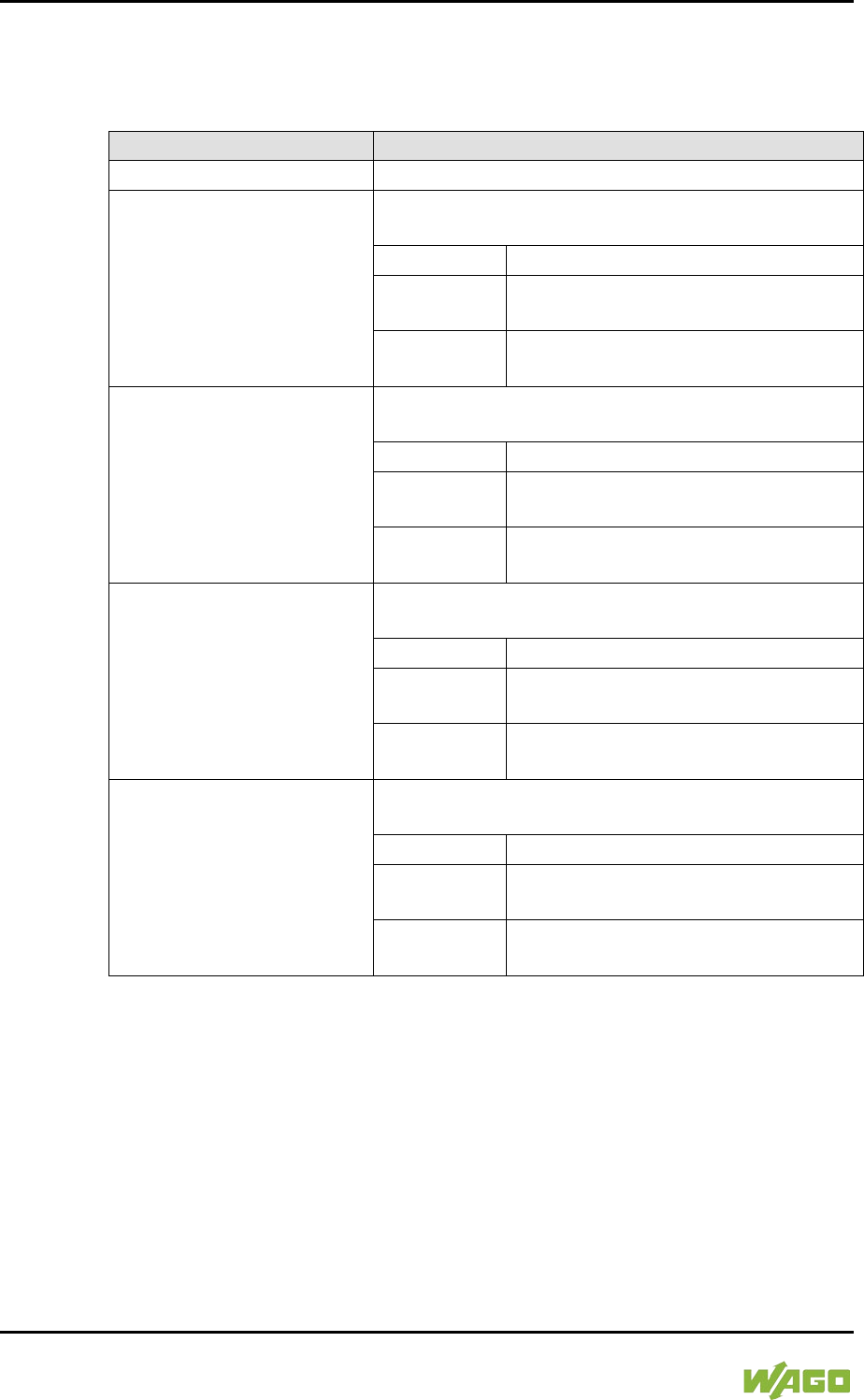
214 Commissioning WAGO-I/O-SYSTEM 750
750-8207 PFC200 CS 2ETH RS 3G
Manual
Draft version 1.2.1 from 2017-09-13, valid from FW Version 02.06.20(09)
7.8.4.12.5 “SNMP” > “(Secure)SNMP firewalling” Submenu
These submenus contain the SNMP firewall settings.
Table 189: “SNMP” > “(Secure )SNMP firewalling” Submenu
Menu Item
Submenu Item / Explanation
0. Back to …
Back to the higher-level menu
1. VPN
Enable or disable the firewall for the VPN interface
and respective service.
0. Back to …
Back to the higher-level menu
1. open
Data traffic via the VPN interface is
permitted.
2. close
Data traffic via the VPN interface is
not permitted.
2. WAN
Enable or disable the firewall for the WAN interface
and respective service.
0. Back to …
Back to the higher-level menu
1. open
Data traffic via the WAN interface is
permitted.
2. close
Data traffic via the WAN interface is
not permitted.
3. X1
Enable or disable the firewall for the X1 interface
and respective service.
0. Back to …
Back to the higher-level menu
1. open
Data traffic via the X1 interface is
permitted.
2. close
Data traffic via the X1 interface is not
permitted.
4. X2
Enable or disable the firewall for the X2 interface
and respective service.
0. Back to …
Back to the higher-level menu
1. open
Data traffic via the X2 interface is
permitted.
2. close
Data traffic via the X2 interface is not
permitted.
To make a selection, choose the appropriate menu item.
To return to the higher-level menu, press [Q].
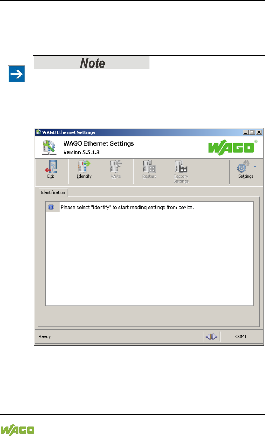
WAGO-I/O-SYSTEM 750 Commissioning 215
750-8207 PFC200 CS 2ETH RS 3G
Manual
Draft version 1.2.1 from 2017-09-13, valid from FW Version 02.06.20(09)
</dg_
7.8.5 Configuration using “WAGO ETHERNET Settings”
The “WAGO ETHERNET Settings” program enables you to read system
information about your controller, make network settings and enable/disable the
Web server.
Observe the software version!
To configure the controller, use at least Version 6.4.1.1 dated 2015-06-29 or
newer of “WAGO ETHERNET Settings”!
You must select the correct COM port after starting “WAGO ETHERNET
Settings”.
Figure 45: “WAGO ETHERNET Settings” – Start Screen
For this, click “Settings” and then “Communication”.
In the “Communication settings” window that then opens, adapt the settings to
your needs.
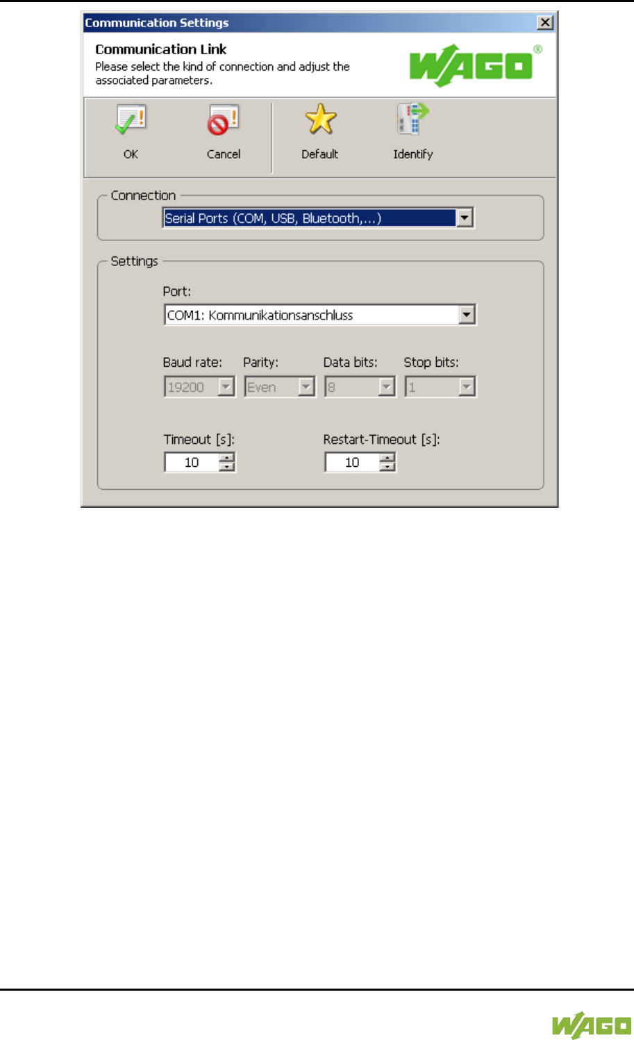
216 Commissioning WAGO-I/O-SYSTEM 750
750-8207 PFC200 CS 2ETH RS 3G
Manual
Draft version 1.2.1 from 2017-09-13, valid from FW Version 02.06.20(09)
Figure 46: “WAGO ETHERNET Settings” – Communication Link
Once you have configured “WAGO ETHERNET Settings” and have clicked [OK],
connection to the controller is established automatically.
If “WAGO ETHERNET Settings” has already been started with the correct
parameters, you can establish connection to the controller by clicking [Identify].
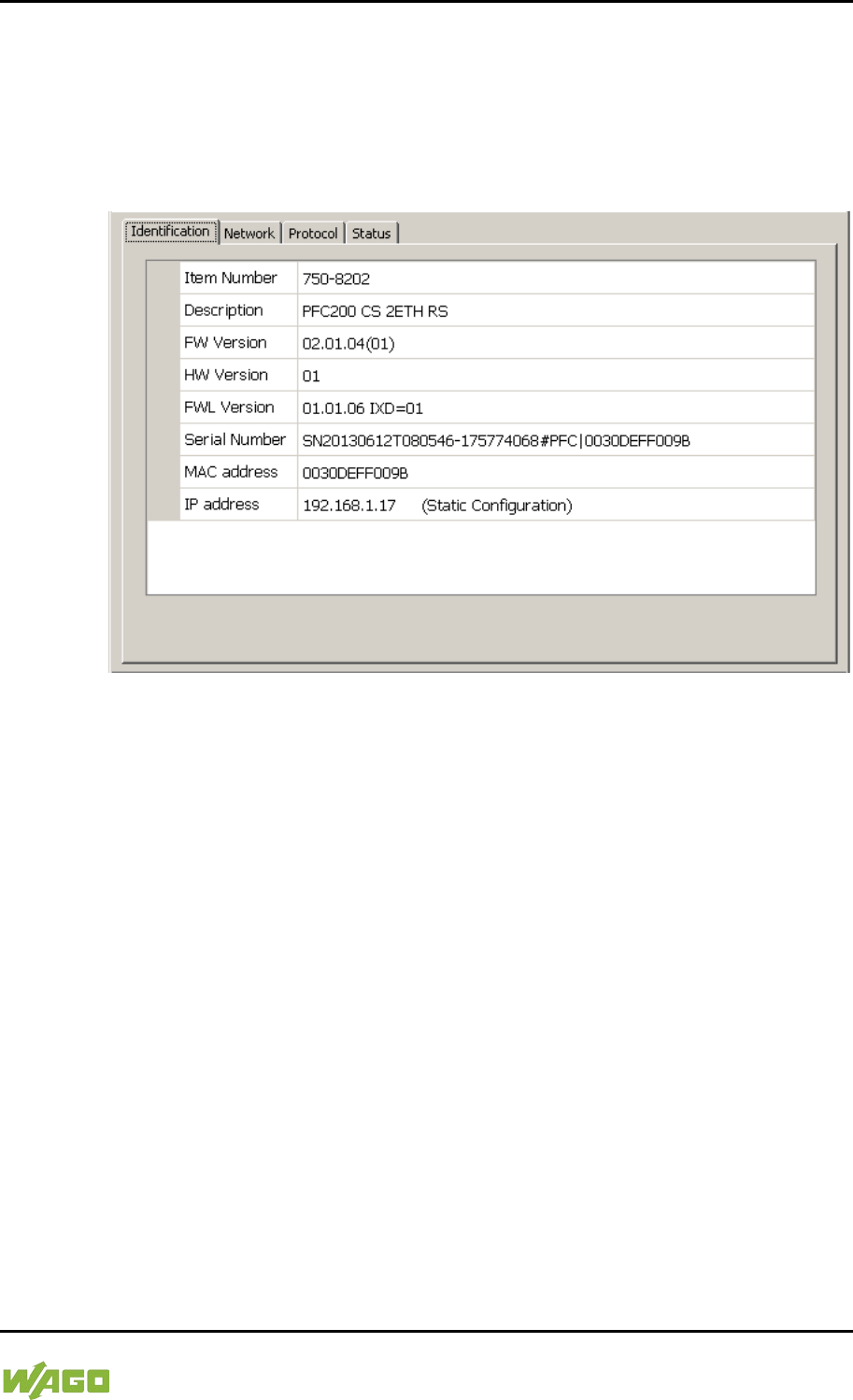
WAGO-I/O-SYSTEM 750 Commissioning 217
750-8207 PFC200 CS 2ETH RS 3G
Manual
Draft version 1.2.1 from 2017-09-13, valid from FW Version 02.06.20(09)
7.8.5.1 Identification Tab
An overview of the connected device is given here.
Besides some fixed values — e.g., item No., MAC address and firmware version
— the currently used IP address and the configuration method are also shown
here.
Figure 47: “WAGO ETHERNET Settings” – Identification Tab (Example)
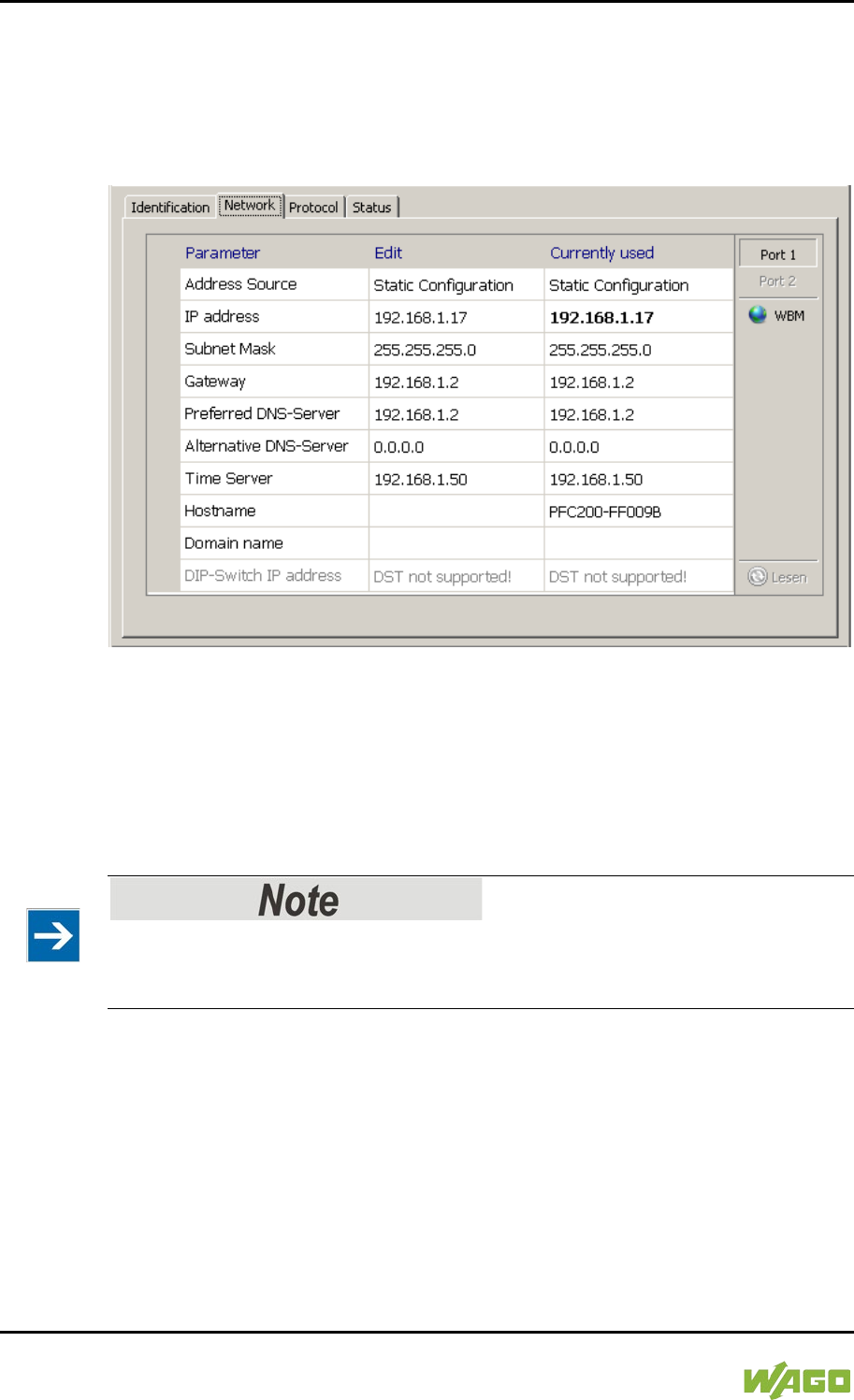
218 Commissioning WAGO-I/O-SYSTEM 750
750-8207 PFC200 CS 2ETH RS 3G
Manual
Draft version 1.2.1 from 2017-09-13, valid from FW Version 02.06.20(09)
7.8.5.2 Network Tab
This tab is used to configure network settings.
Values can be changed in the “Input” column, while the parameters in use are
shown in the “Currently in use” column.
Figure 48: “WAGO ETHERNET Settings” – Network Tab
Source
Specify how the controller will determine its IP address: Static, via DHCP or via
BootP.
IP address, subnet mask, gateway
Specify the specific network parameters for static configuration.
Restricted setting for default gateways!
Only the default gateway 1 can be set via “WAGO Ethernet Settings.”
The default gateway 2 can only be set in the WBM!
Preferred DNS server, alternative DNS server
Enter the IP address (when required) for an accessible DNS server when
identifying network names.
Time server
Specify the IP address for a time server if setting the controller's system time via
NTP.
Host name
The host name of the controller is displayed here. In the controller's initial state,

WAGO-I/O-SYSTEM 750 Commissioning 219
750-8207 PFC200 CS 2ETH RS 3G
Manual
Draft version 1.2.1 from 2017-09-13, valid from FW Version 02.06.20(09)
this name is composed of the string “PFCx00” and the last three bytes of the
MAC address.
This standard value is also used whenever the chosen name in the “Input”
column is deleted.
Domain name
The current domain name is displayed here. This setting can be automatically
overwritten with dynamic configurations, e.g., DHCP.
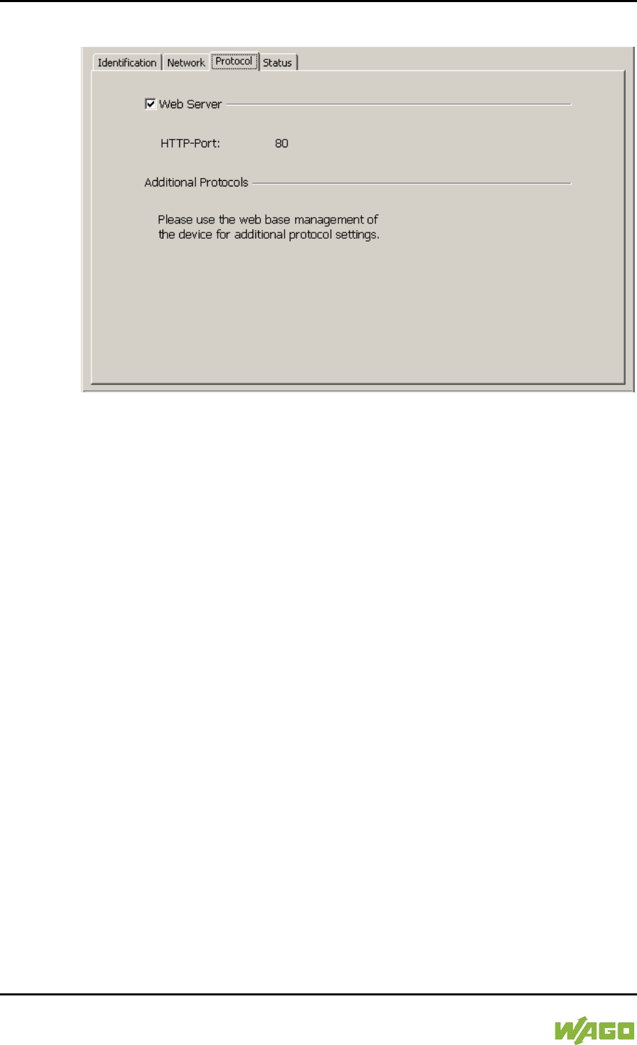
220 Commissioning WAGO-I/O-SYSTEM 750
750-8207 PFC200 CS 2ETH RS 3G
Manual
Draft version 1.2.1 from 2017-09-13, valid from FW Version 02.06.20(09)
7.8.5.3 Protocol Tab
Figure 49: “WAGO ETHERNET Settings” – Protocol Tab
You can enable or disable the Web server.

WAGO-I/O-SYSTEM 750 Commissioning 221
750-8207 PFC200 CS 2ETH RS 3G
Manual
Draft version 1.2.1 from 2017-09-13, valid from FW Version 02.06.20(09)
7.8.5.4 Status Tab
Figure 50: “WAGO ETHERNET Settings” – Status Tab
General information about the controller status is displayed here.
The Bus extension check box has no function for the controller PFCx00, i.e., the
bus extension is always active.
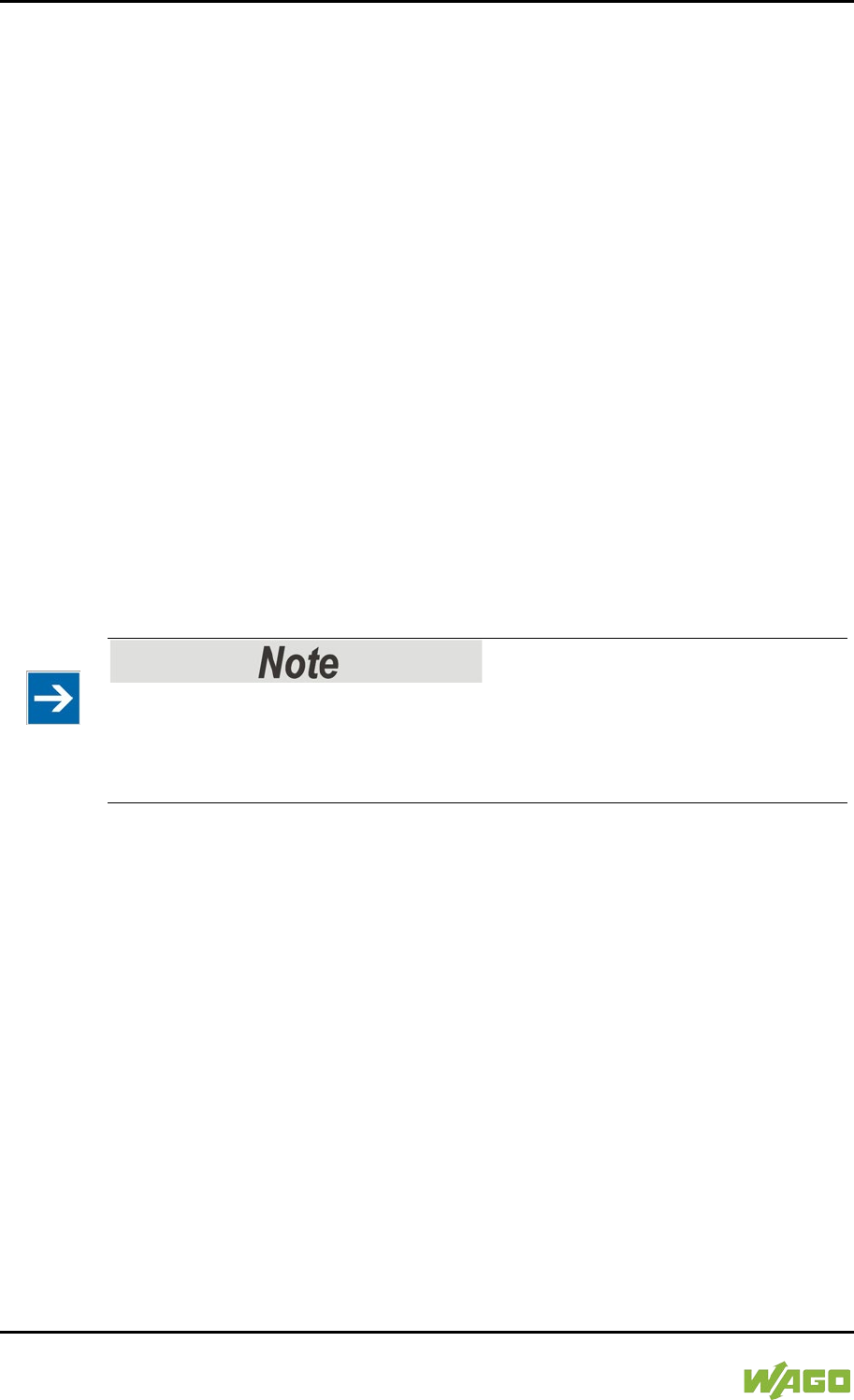
222 Run-time System CODESYS 2.3 WAGO-I/O-SYSTEM 750
750-8207 PFC200 CS 2ETH RS 3G
Manual
Draft version 1.2.1 from 2017-09-13, valid from FW Version 02.06.20(09)
8 Run-time System CODESYS 2.3
8.1 Installing the CODESYS 2.3 Programming System
The WAGO target files must also be included for the installation of CODESYS.
These contain all device-specific information for the WAGO 750/758 product
series.
Proceed as described below to install the CODESYS 2.3 programming software
on a personal computer.
1. Insert the “WAGO-I/O-PRO” CD into your computer drive.
2. To install the programming system, follow the instructions that appear on
your screen. A successful installation is indicated by a CODESYS icon on
your desktop.
8.2 First Program with CODESYS 2.3
This section uses an example to explain the relevant steps required for the
creation of a CODESYS project. It is intended as a set of quick start instructions
and does not address the full functional range of CODESYS 2.3.
Additional information
For a detailed description of the full range of functions, refer to the “Manual for
PLC Programming using CODESYS 2.3” manual available on the “WAGO-I/O-
PRO” (759-911) CD.
8.2.1 Start the CODESYS Programming System
Start CODESYS by double clicking on the CODESYS pictogram on your desktop
using the Start menu in your operating system. To do this, click on the “Start”
button and choose Programs >
WAGO Software > CODESYS > CODESYS V2.3.
8.2.2 Creating a Project and Selecting the Target System
1. In the menu bar click on File and select New. The “Target system settings”
window then opens. Here, all available target systems that can be
programmed with CODESYS 2.3 are listed.
2. Open the selection box in the “Target system settings” window and select
the fieldbus controller you are using. In the example show here this is the
PFC200 CS 2ETH RS 3G “WAGO_750-8207”.
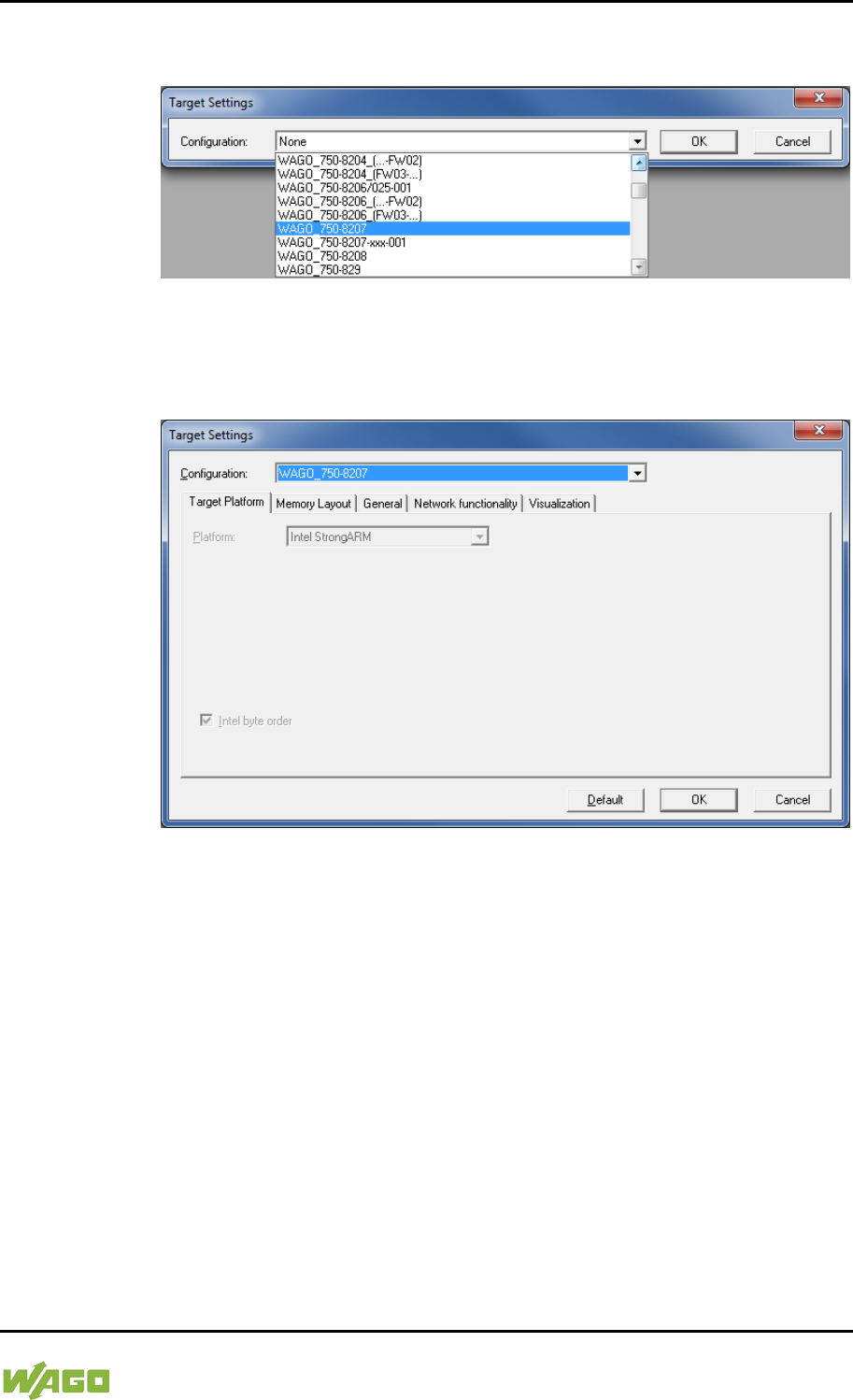
WAGO-I/O-SYSTEM 750 Run-time System CODESYS 2.3 223
750-8207 PFC200 CS 2ETH RS 3G
Manual
Draft version 1.2.1 from 2017-09-13, valid from FW Version 02.06.20(09)
3. Click on [OK]. The “Target system settings” configuration window then
opens.
Figure 51: Target System Settings (1)
4. To accept the default configuration for the fieldbus controller click [OK].
The “New component” window opens.
Figure 52: Target System Settings (2)
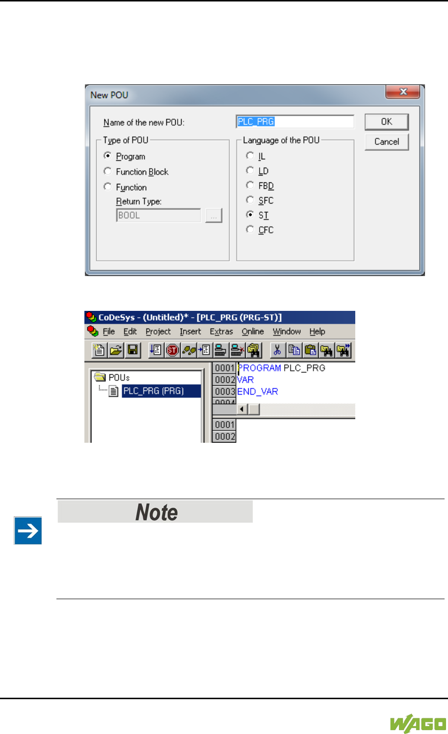
224 Run-time System CODESYS 2.3 WAGO-I/O-SYSTEM 750
750-8207 PFC200 CS 2ETH RS 3G
Manual
Draft version 1.2.1 from 2017-09-13, valid from FW Version 02.06.20(09)
5. In this “New component” window create a new program function block. In
the example shown here, the new function block “PLC_PRG” is created in
the “ST” programming language.
6. Click on [OK] to create the project. The programming interface opens.
Figure 53: Creating a New Function Block
Figure 54: Programming Interface with the PLC_PRG Program Module
8.2.3 Creating the PLC Configuration
Procedure for Creating the PLC Configuration
The procedure explained in this section describes the PLC configuration for the
I/O modules connected to the controller.
Information about the controller function for any fieldbuses connected to the
system is given in the section on the specific fieldbus.
The PLC configuration is used to configure the fieldbus controller, along with the
connected I/O modules and to declare variables for accessing the inputs and
outputs of the I/O modules.
1. Click on the “Resources” tab.
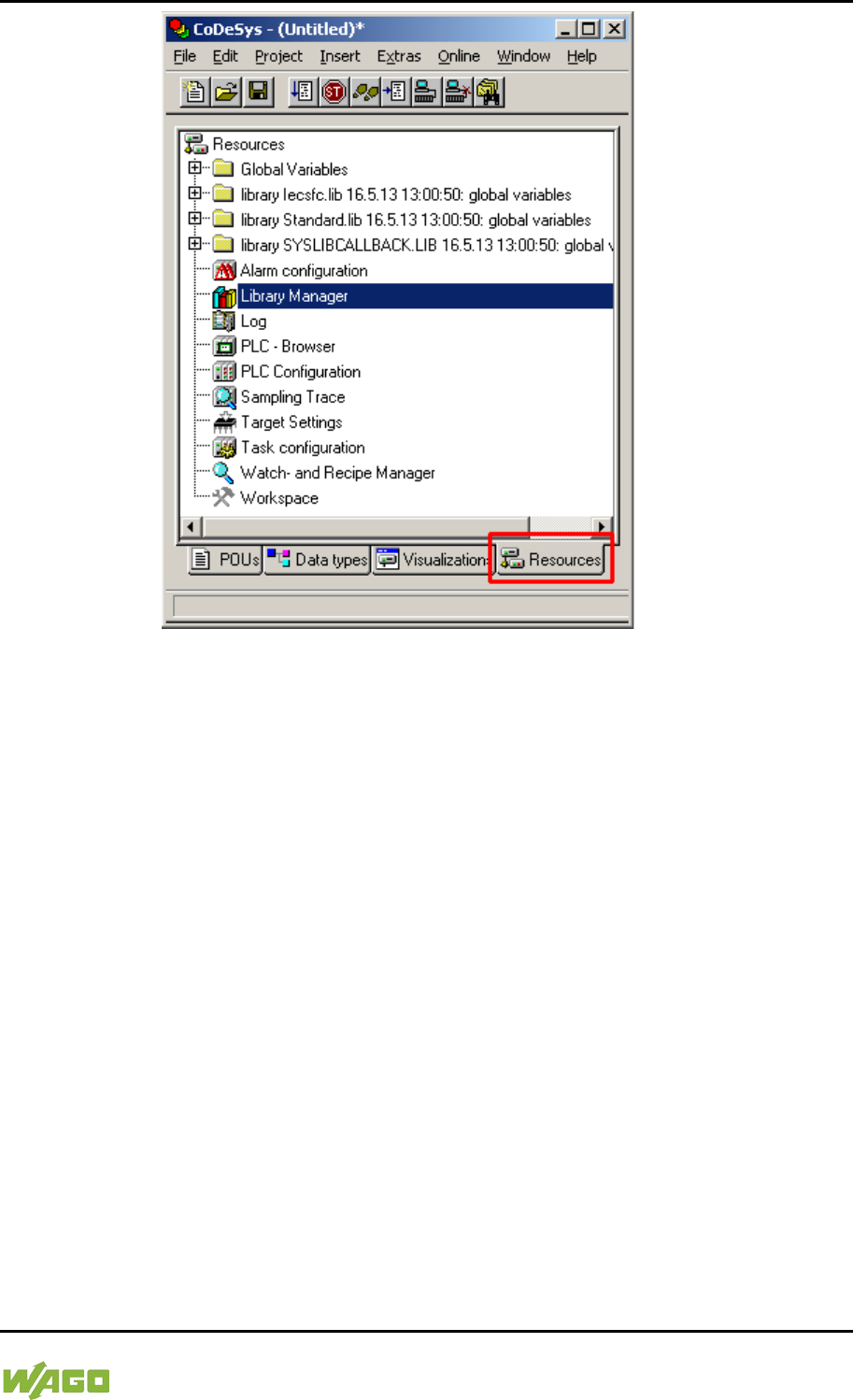
WAGO-I/O-SYSTEM 750 Run-time System CODESYS 2.3 225
750-8207 PFC200 CS 2ETH RS 3G
Manual
Draft version 1.2.1 from 2017-09-13, valid from FW Version 02.06.20(09)
Figure 55: “Resources” Tab
2. In the left window double-click on “PLC configuration”. The PLC
configuration for the controller opens.
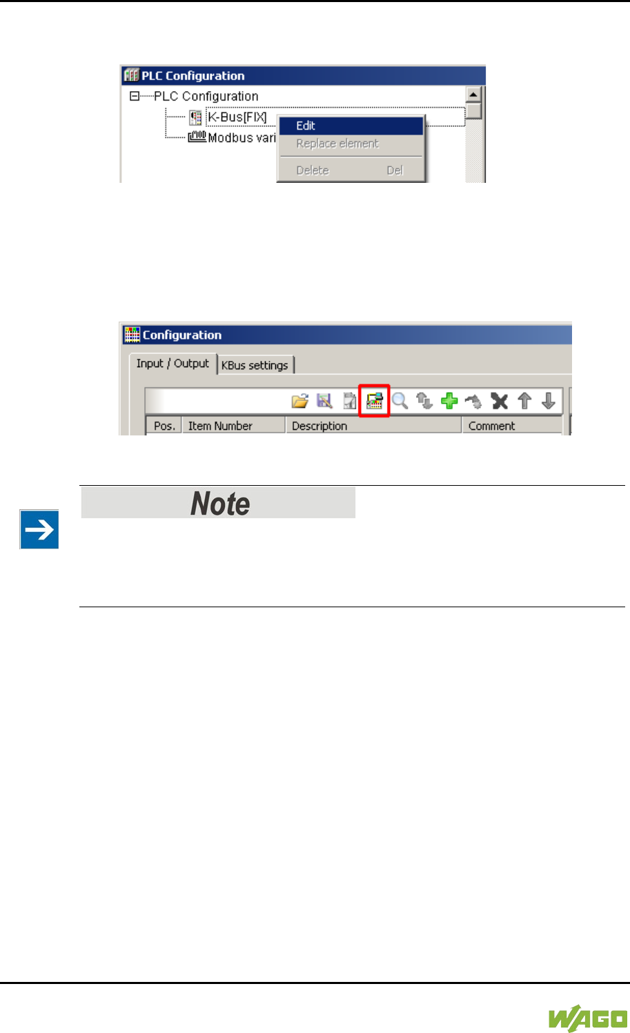
226 Run-time System CODESYS 2.3 WAGO-I/O-SYSTEM 750
750-8207 PFC200 CS 2ETH RS 3G
Manual
Draft version 1.2.1 from 2017-09-13, valid from FW Version 02.06.20(09)
3. Right-click on the entry “K-Bus[FIX]” and then select “Edit” in the contextual
menu. The “configuration” dialog window then opens.
Figure 56: Control Configuration – Edit
4. There are three options for accepting the topology for the I/O modules
connected to the fieldbus controller. The simplest way is to scan in the
topology using WAGO-I/O-CHECK.
To do this, click on the “Start WAGO-I/O-CHECK and scan” button.
Figure 57: “Start WAGO-I/O-CHECK and Scan” Button
Ensure proper installation of WAGO-I/O-CHECK!
This function requires that the latest version of WAGO-I/O-CHECK be installed
and the IP address set under “Online > Communication parameters”, as
otherwise communication will not be possible.
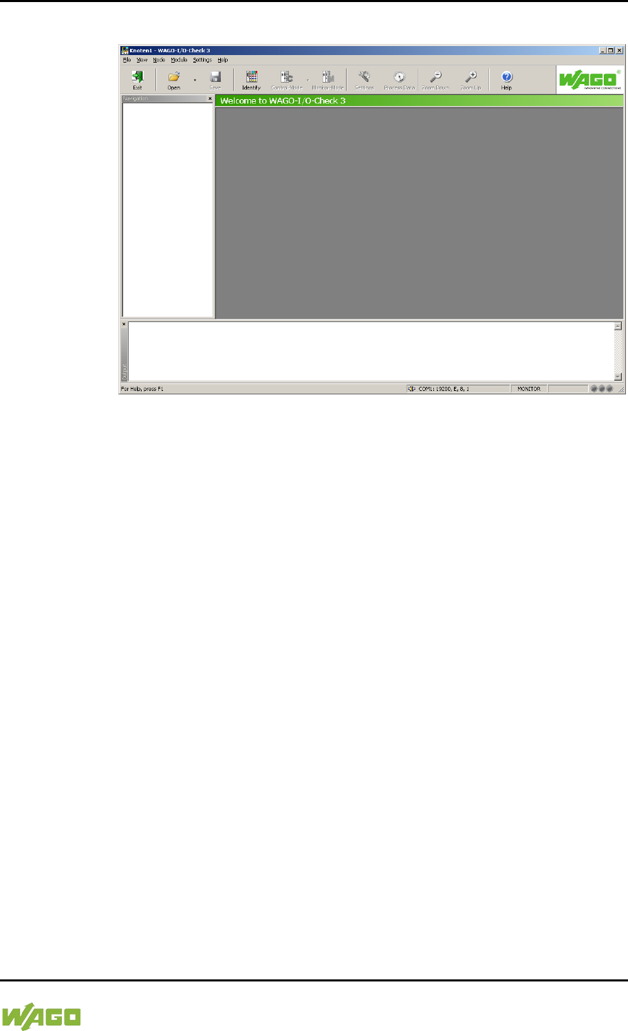
WAGO-I/O-SYSTEM 750 Run-time System CODESYS 2.3 227
750-8207 PFC200 CS 2ETH RS 3G
Manual
Draft version 1.2.1 from 2017-09-13, valid from FW Version 02.06.20(09)
5. WAGO-I/O-CHECK is started.
Figure 58: WAGO-I/O-CHECK – Starting Screen
6. To connect to the controller and read in the module configuration, click
[Identify].
7. If this action is successful click [Save] and exit WAGO-I/O-CHECK.
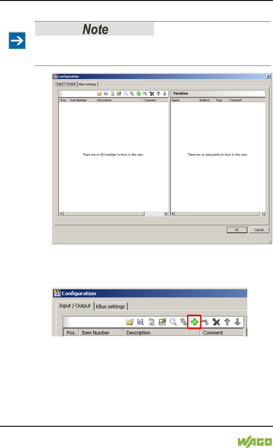
228 Run-time System CODESYS 2.3 WAGO-I/O-SYSTEM 750
750-8207 PFC200 CS 2ETH RS 3G
Manual
Draft version 1.2.1 from 2017-09-13, valid from FW Version 02.06.20(09)
8. The detected I/O modules then appear in the configuration window.
Passive I/O Modules
Remember that passive I/O modules, such as a power supply module (750-602)
or end module (750-600) will not be shown in the I/O configurator.
Figure 59: I/O Configurator Empty
9. You can use the [Add] button to add new I/O modules to manually define
or change the configuration.
Figure 60: “Add I/O Modules” Button
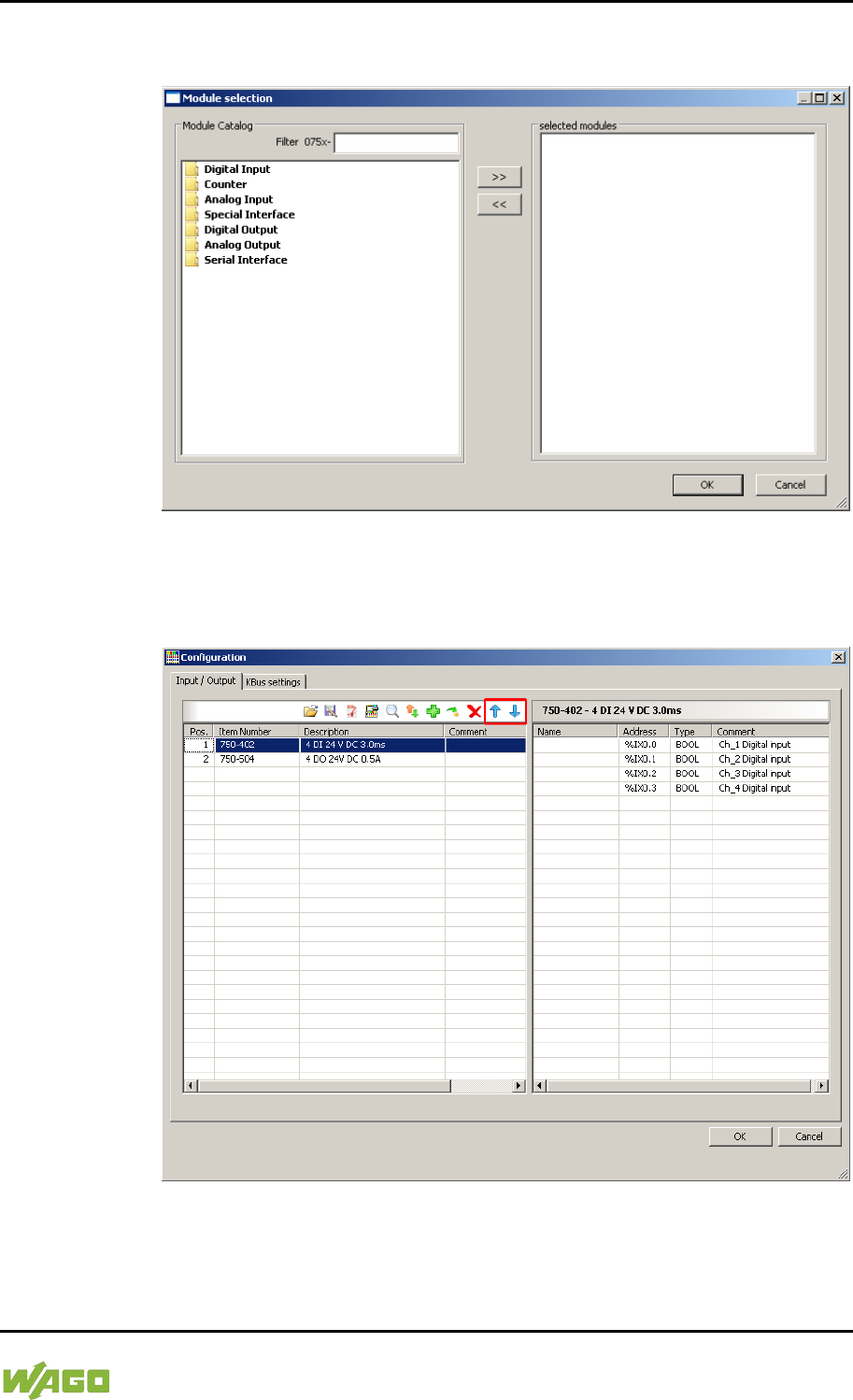
WAGO-I/O-SYSTEM 750 Run-time System CODESYS 2.3 229
750-8207 PFC200 CS 2ETH RS 3G
Manual
Draft version 1.2.1 from 2017-09-13, valid from FW Version 02.06.20(09)
10. You can select a module in the new “Module selection” window that then
appears.
Figure 61: “Module Selection” Window
11. You can change the position of an I/O module by marking it and then using
the arrow buttons at the right edge of the window to move it up or down.
Figure 62: I/O Configurator with Defined I/O Modules
12. Use [Import configuration from file] to add a configuration imported
previously using WAGO-I/O-CHECK.
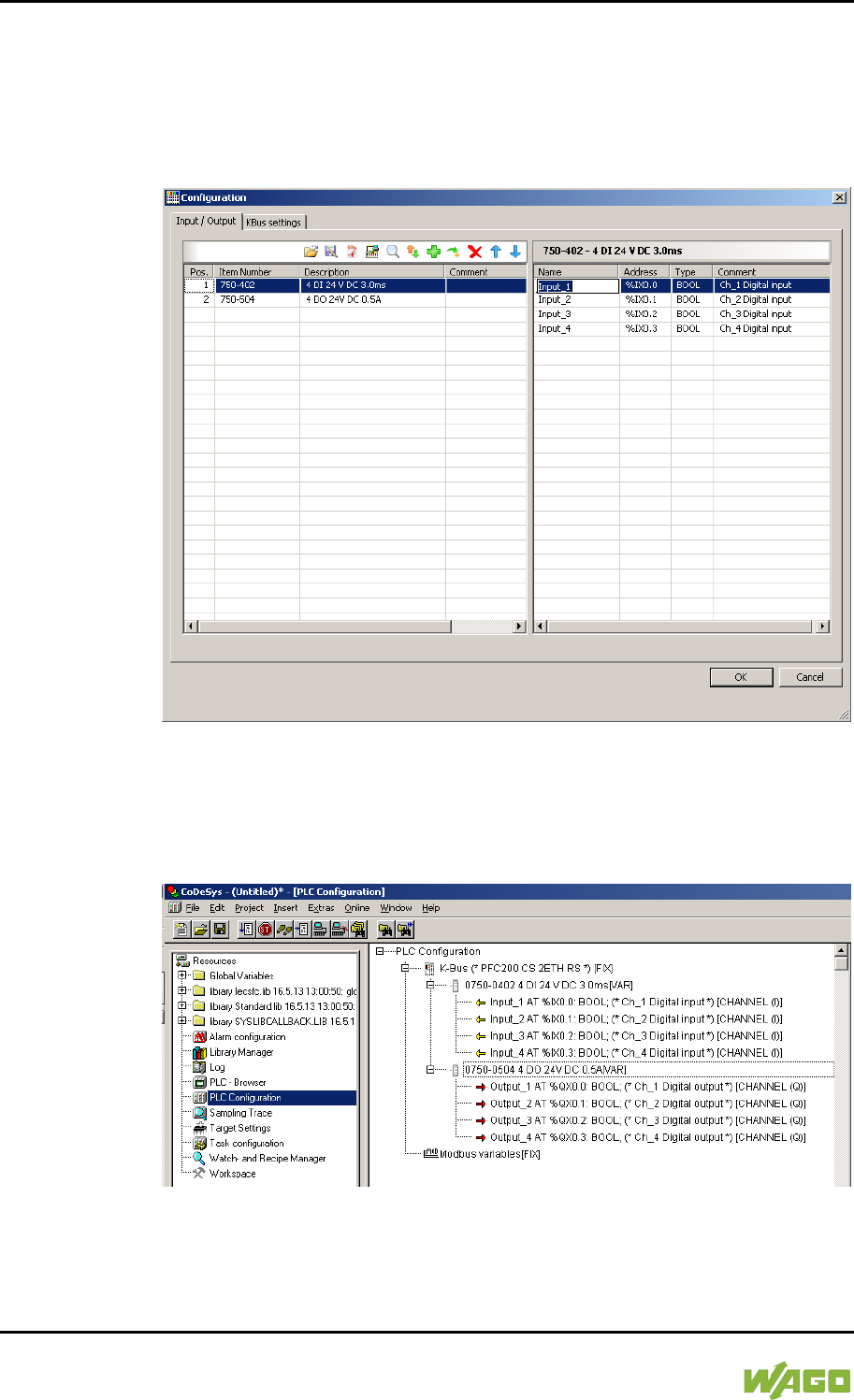
230 Run-time System CODESYS 2.3 WAGO-I/O-SYSTEM 750
750-8207 PFC200 CS 2ETH RS 3G
Manual
Draft version 1.2.1 from 2017-09-13, valid from FW Version 02.06.20(09)
13. To close the I/O Configurator, click [OK].
14. The individual inputs and outputs of the selected I/O module are displayed
in the right half of the configuration window.
Here, you can declare a dedicated variable in the “Name” column for each
input and output, e.g., “Output_1”, “Output_2”, “Input_1”, “Input_2”.
Figure 63: Variable declaration
15. The added I/O modules appear in the control configuration under
“K-Bus[FIX]” with their associated fixed addresses and, where applicable,
their previously set variable name.
Figure 64: Control Configuration: I/O Modules with Their Associated Addresses
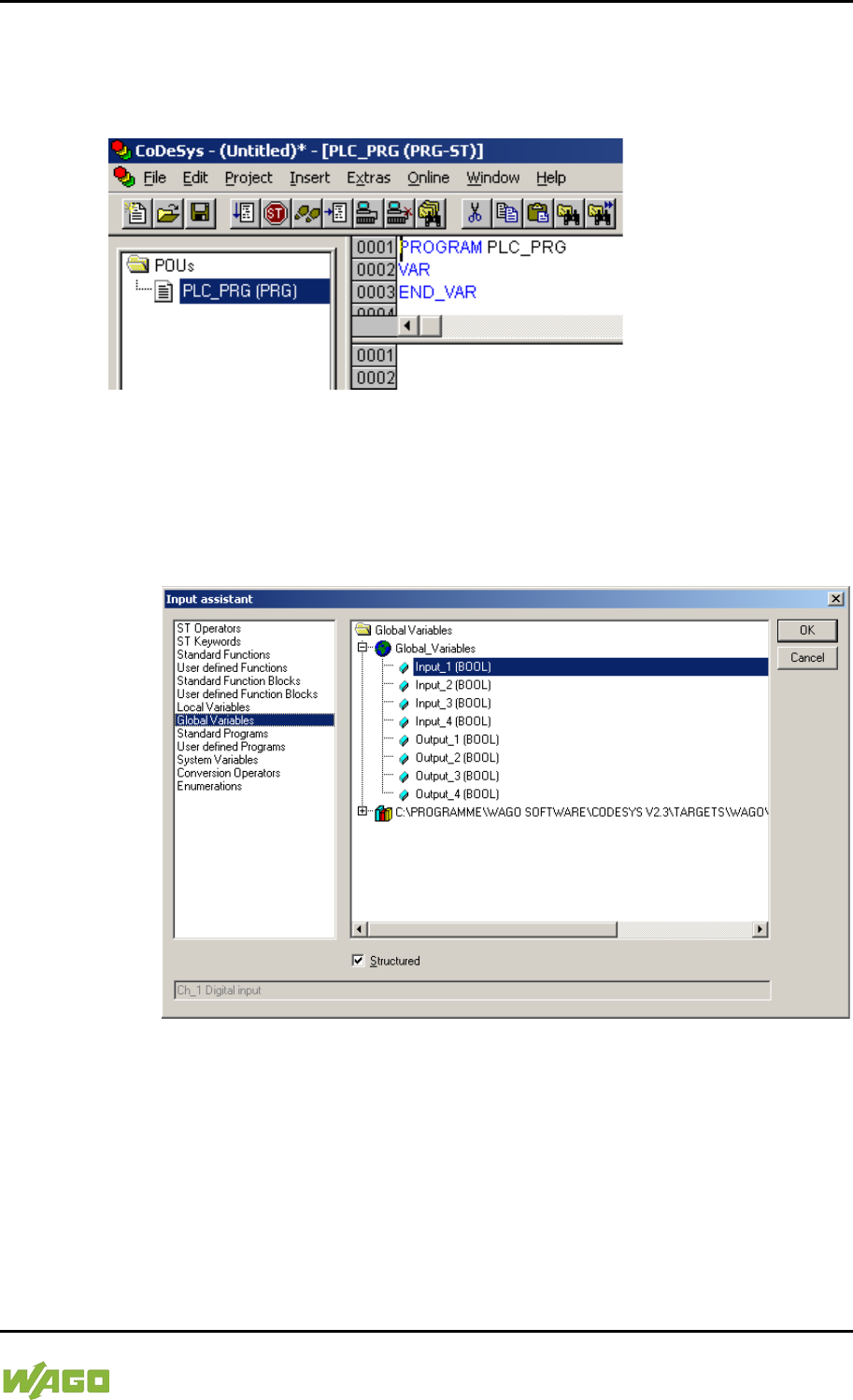
WAGO-I/O-SYSTEM 750 Run-time System CODESYS 2.3 231
750-8207 PFC200 CS 2ETH RS 3G
Manual
Draft version 1.2.1 from 2017-09-13, valid from FW Version 02.06.20(09)
8.2.4 Editing the Program Function Block
To edit the PLC_PRG program function block, go to the “Function block” tab and
double-click on the PLC_PRG program module.
Figure 65: Program Function Block
The following example illustrates the editing of the program function block. To do
this, an input is assigned to an output:
1. Press [F2] to open the Input assistant, or right click and select “Input
assistant” from the contextual menu.
Figure 66: Input Assistant for Selecting Variables
2. Under “Global variables” select the previously declared variable “Output_1”
and click [OK] to add it.
3. Enter the allocation “=” behind the variable name.
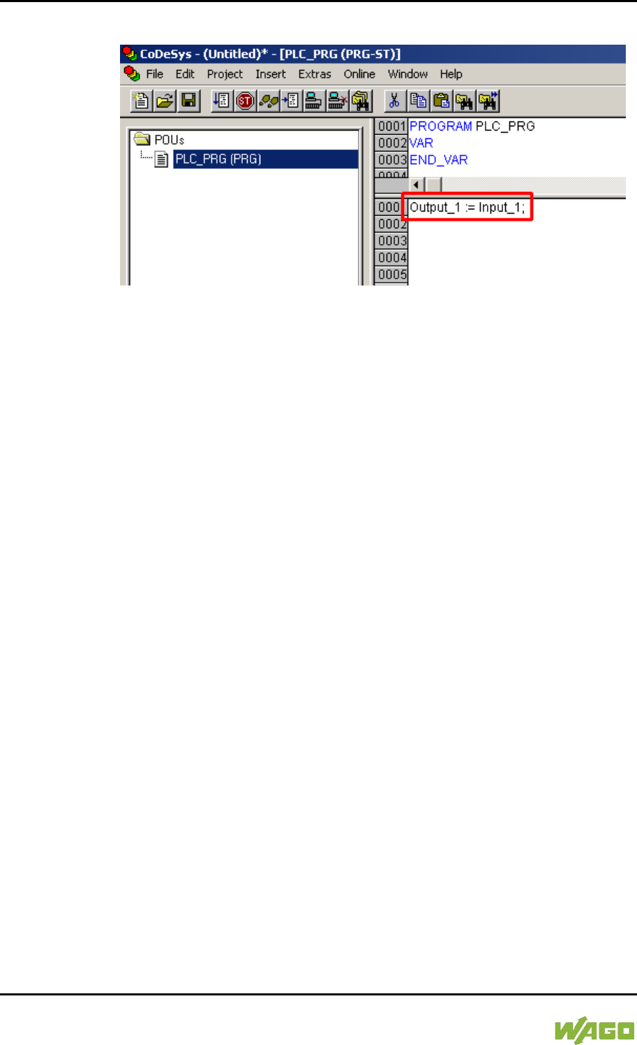
232 Run-time System CODESYS 2.3 WAGO-I/O-SYSTEM 750
750-8207 PFC200 CS 2ETH RS 3G
Manual
Draft version 1.2.1 from 2017-09-13, valid from FW Version 02.06.20(09)
4. Repeat Step 2 for the “Input_1” variable.
Figure 67: Example of an Allocation
5. To compile, click on Project > Compile all in the menu bar.
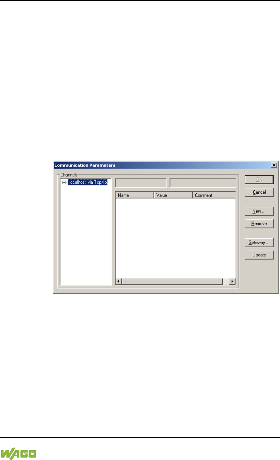
WAGO-I/O-SYSTEM 750 Run-time System CODESYS 2.3 233
750-8207 PFC200 CS 2ETH RS 3G
Manual
Draft version 1.2.1 from 2017-09-13, valid from FW Version 02.06.20(09)
8.2.5 Loading and Running the PLC Program in the Fieldbus
Controller (ETHERNET)
Requirement:
- The simulation is deactivated (Online > Simulation).
- The PC is linked to the controller via ETHERNET. Refer to Section “Device
Description” > …> “ETHERNET – X1, X2 Network Connection”.
Proceed as follows:
1. In the menu bar click on Online and select Communication parameters
…. The “Communication Parameters” window opens.
2. To select a communication link, click on [New …] in the “Communication
Parameters” window. A window opens in which you can define a
communication link.
Figure 68: Creating a Communication Link – Step 1
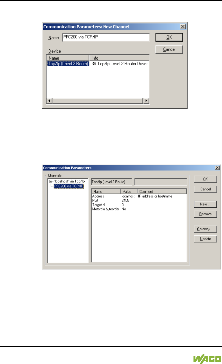
234 Run-time System CODESYS 2.3 WAGO-I/O-SYSTEM 750
750-8207 PFC200 CS 2ETH RS 3G
Manual
Draft version 1.2.1 from 2017-09-13, valid from FW Version 02.06.20(09)
3. In the “Name” field enter a designation for your fieldbus controller and then
click on “Tcp/Ip (Level 2 Route)”. Then click [OK].
Figure 69: Creating a Communication Link – Step 2
4. In the “Communication Parameters” window enter the IP address of your
fieldbus controller in the “Address” field and then press Enter. To close
the window, click on [OK].
To select an already created controller, select it in the left window and then
click on [OK].
Figure 70: Creating a Communication Link – Step 3
5. Transfer the PLC program by clicking on Online in the menu bar and select
Login.
6. Ensure that the Run/Stop switch for the fieldbus controller is set to “Run”.
7. Start the PLC program by clicking on Online > Start in the menu bar.
WAGO-I/O-SYSTEM 750 Run-time System CODESYS 2.3 235
750-8207 PFC200 CS 2ETH RS 3G
Manual
Draft version 1.2.1 from 2017-09-13, valid from FW Version 02.06.20(09)
8.2.6 Creating a Boot Project
Create a boot project to ensure that the PLC program starts automatically again
after a fieldbus controller restart. In the menu bar select Online > Create boot
project. You must be logged in to CODESYS to use this function.
Automatic loading of the boot project
In addition, you can load the boot project automatically when starting the
fieldbus controller. Click on the “Resources” tab and open “Target system
settings”. Select the “General” tab and “Load boot project automatically”.
If a boot project (DEFAULT.PRG and DEFAULT.CHK) is present under
/home/codesys and the “Run/Stop” switch of the fieldbus controller is set to
“Run”, the fieldbus controller automatically starts with the processing of the PLC
program. The PLC program is not started if the switch is set to “Stop”.
If a PLC program is running in the fieldbus controller, a PLC task starts with the
reading of the fieldbus data (only with fieldbus controllers and fieldbus
connection), the integrated input and output data and the I/O modules. The
output data changed in the PLC program is updated after the PLC task is
processed. A change in operating mode (“Stop/Run”) is only carried out at the
end of a PLC task. The cycle time includes the time from the start of the PLC
program to the next start. If a larger loop is programmed within a PLC program,
the task time is prolonged accordingly. The inputs and outputs are updated
during processing. These updates only take place at the end of a PLC task.
8.3 Syntax of Logical Addresses
Access to individual memory elements according to IEC 61131-3 is possible
using only the following special symbols:
Table 190: Syntax of Logical Addresses
Item
Prefix
Description
Notes:
1
%
Starts the absolute address
-
2
I
Input
Q
Output
M
Flag
3
X
Single bit
Data width
B-
Byte (8 bits)
W
Word (16 bits)
D
Double word (32 bits)
4
Address
Two examples:
Addressing by word %QW27 (28th word)
Addressing by bit %IX1.9 (10th bit in word 2)
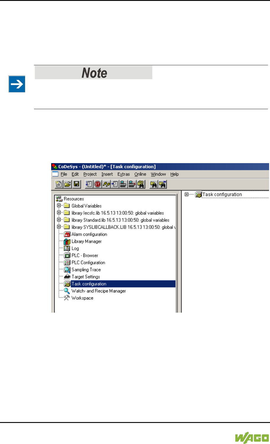
236 Run-time System CODESYS 2.3 WAGO-I/O-SYSTEM 750
750-8207 PFC200 CS 2ETH RS 3G
Manual
Draft version 1.2.1 from 2017-09-13, valid from FW Version 02.06.20(09)
Enter the character string of the absolute address without empty spaces. The first
bit of a word has an address of 0.
8.4 Creating Tasks
Set the time response and the priority of individual tasks in the task configuration.
Watchdog
In an application program without task configuration, there is no watchdog that
monitors the cycle time of the application program (PLC_PRG).
Create a task as follows:
1. Open the task configuration by double-clicking on the “Task configuration”
module in the “Resources” tab.
Figure 71: Task Configuration
2. To create a task right-click on “Task configuration” and in the contextual
menu select “Attach task”.
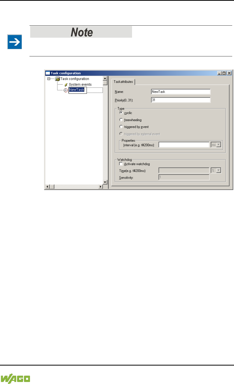
WAGO-I/O-SYSTEM 750 Run-time System CODESYS 2.3 237
750-8207 PFC200 CS 2ETH RS 3G
Manual
Draft version 1.2.1 from 2017-09-13, valid from FW Version 02.06.20(09)
3. To assign a new name to the task (e.g. PLC_Prog), click on “New Task”.
Then select the type of task. In this example, this is the “cyclic” type.
Observe the cycle time!
The minimum cycle time for I/O-based tasks is 2 milliseconds (ms)!
Figure 72: Changing Task Names 1
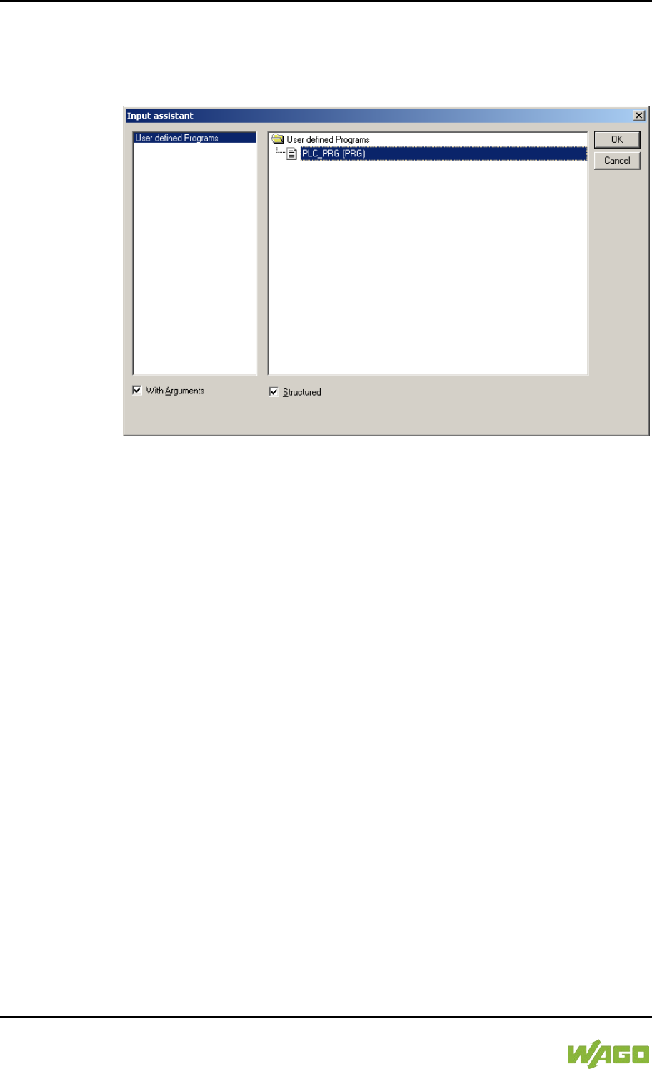
238 Run-time System CODESYS 2.3 WAGO-I/O-SYSTEM 750
750-8207 PFC200 CS 2ETH RS 3G
Manual
Draft version 1.2.1 from 2017-09-13, valid from FW Version 02.06.20(09)
4. Add the program module PLC_PRG that you have just created (see
Section “Editing the Program Modules”). To do this, right-clock on the
“Clock” symbol and in the contextual menu select “Attach program call-up”.
Then, click the [...] button and [OK].
Figure 73: Call-up to Add to the Program Module
5. Compile the example program by selecting Project > Rebuild all in the
context menu.
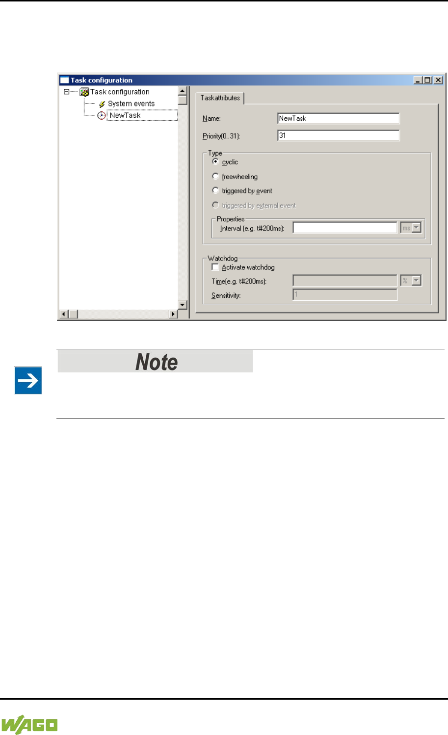
WAGO-I/O-SYSTEM 750 Run-time System CODESYS 2.3 239
750-8207 PFC200 CS 2ETH RS 3G
Manual
Draft version 1.2.1 from 2017-09-13, valid from FW Version 02.06.20(09)
8.4.1 Cyclic Tasks
You can assign a priority for each task in order to establish the task processing
sequence.
Figure 74: Cyclic Task
Order of Task Processing
The priorities given below do not specifiy the order of task processing. The tasks
start in an arbitrary order.
Priority 0 … 5:
Important arithmetic operations and synchronized access to I/O module process
images are to be carried out as tasks with the highest priorities 0 … 5. These
tasks are processed fully according to priority and correspond to Linux® RT
priorities
-79 through -74.
Priority 6 … 20:
Real-time access, such as access to ETHERNET and the file system, to fieldbus
data and to the RS-232 interface (when available) are to be carried out as tasks
with average priorities 6 … 20. These tasks are processed fully according to
priority and correspond to Linux® RT priorities -40 through -26.
Priority 21 … 31:
Applications such as long-lasting arithmetic operations and non-real-time-
relevant access to ETHERNET and the file system, to fieldbus data and the RS-
232 interface (when provided) are to be carried out as tasks with the lowest
priorities 21 … 31. No prioritiy distinction is made between tasks of priorities 21
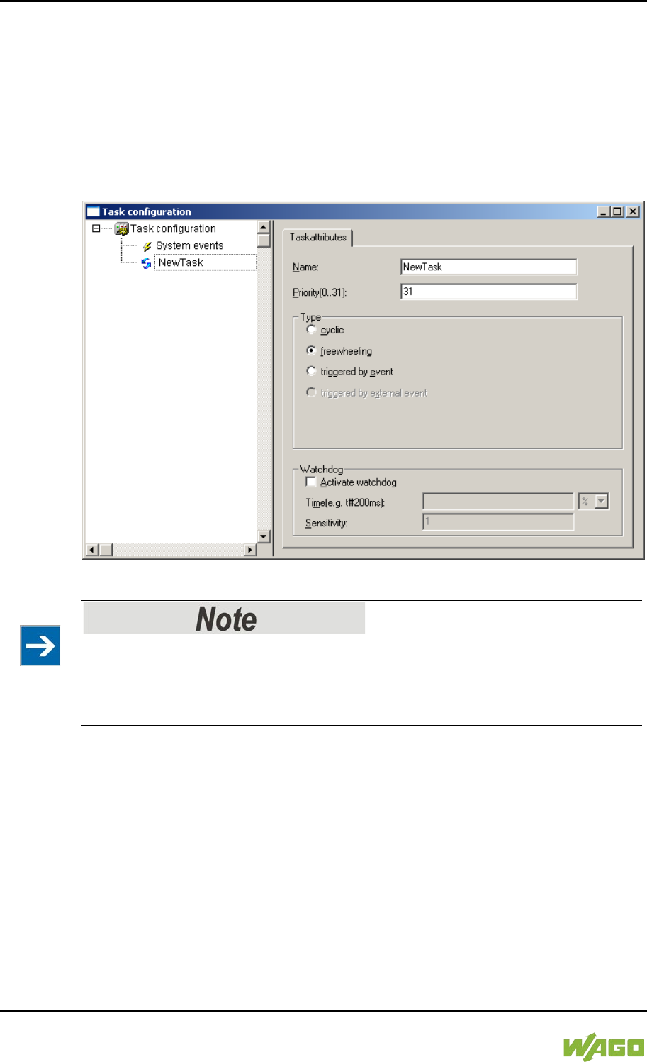
240 Run-time System CODESYS 2.3 WAGO-I/O-SYSTEM 750
750-8207 PFC200 CS 2ETH RS 3G
Manual
Draft version 1.2.1 from 2017-09-13, valid from FW Version 02.06.20(09)
… 31. These tasks all receive the same computing time from the operating
system (“Completely Fair Scheduler” procedure).
8.4.2 Freewheeling Tasks
So-called freewheeling tasks are not processed in cycles. Their processing
depends solely on the current capacity of the system. The input field “Priority
(0 … 31)” is provided for freewheeling tasks without a function. These tasks are
handled as tasks with priority 21 … 31.
Figure 75: Freewheeling Task
PLC-PRG as Freewheeling Task without Task Configuration
If you do not perform any task configuration, the program PLC_PRG is carried
out with the lowest priority at an interval of 10 ms. The runtime of “freewheeling
tasks” is not monitored by a CODESYS watchdog.
8.4.3 Debugging an IEC Program
If the IEC program is debugged with breakpoints, the behavior on actuation of the
mode selector switch is defined as follows:
Provided that a task is not located on a breakpoint, RUN and STOP from the user
interface (IDE) and from the mode selector switch (BAS) always have an effect
on all tasks (case 1 and case 2).
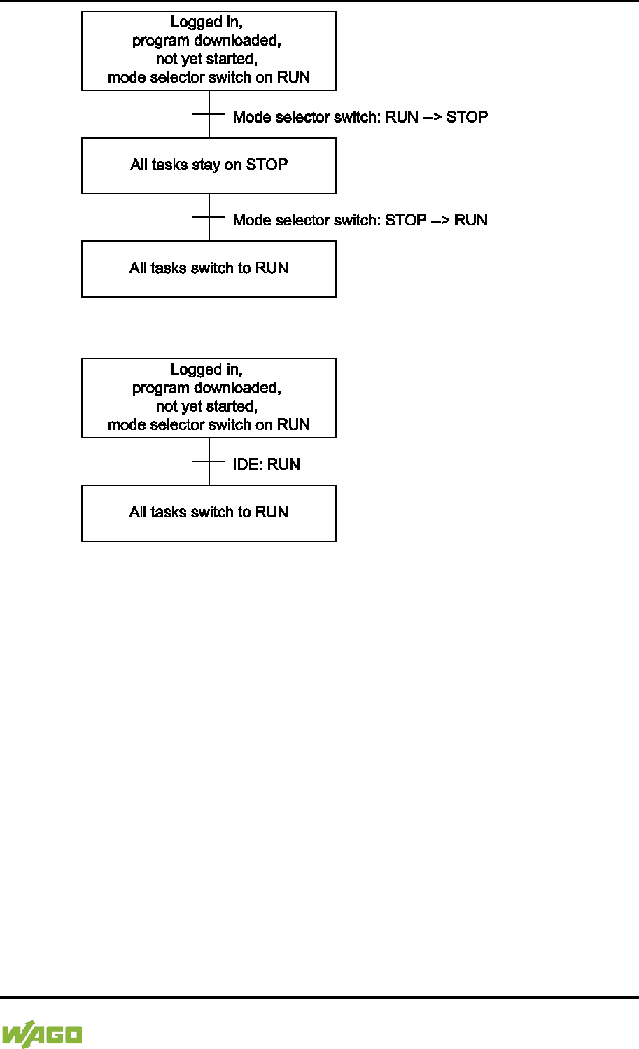
WAGO-I/O-SYSTEM 750 Run-time System CODESYS 2.3 241
750-8207 PFC200 CS 2ETH RS 3G
Manual
Draft version 1.2.1 from 2017-09-13, valid from FW Version 02.06.20(09)
Figure 76: Debugging (Case 1)
Figure 77: Debugging (Case 2)
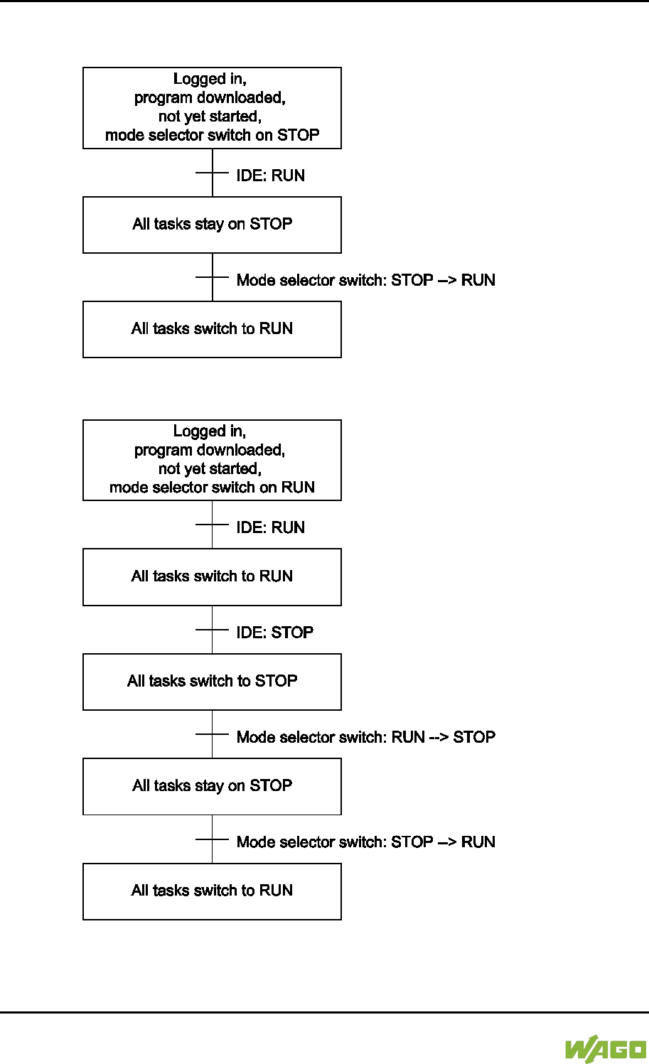
242 Run-time System CODESYS 2.3 WAGO-I/O-SYSTEM 750
750-8207 PFC200 CS 2ETH RS 3G
Manual
Draft version 1.2.1 from 2017-09-13, valid from FW Version 02.06.20(09)
If the mode selector switch and the STOP function of the user interface are used
simultaneously, the mode selector switch has priority (case 3 and case 4).
Figure 78: Debugging (Case 3)
Figure 79: Debugging (Case 4)
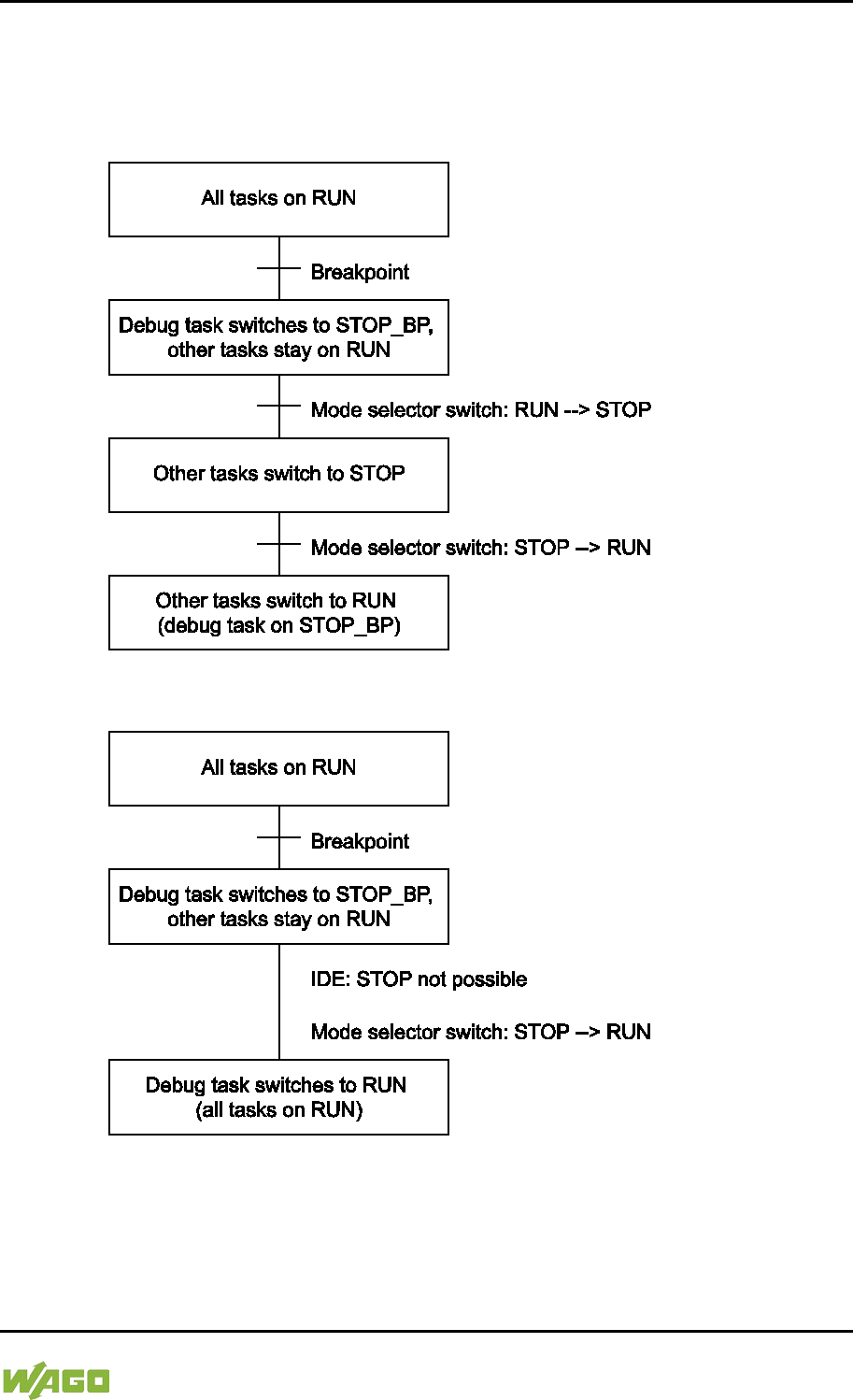
WAGO-I/O-SYSTEM 750 Run-time System CODESYS 2.3 243
750-8207 PFC200 CS 2ETH RS 3G
Manual
Draft version 1.2.1 from 2017-09-13, valid from FW Version 02.06.20(09)
As soon as a task is located at a breakpoint, only all other tasks can be controlled
with the mode selector switch.
Exception: If the mode selector switch is on STOP, the debug task is also no
longer processed.
Figure 80: Debugging (Case 5)
Figure 81: Debugging (Case 6)
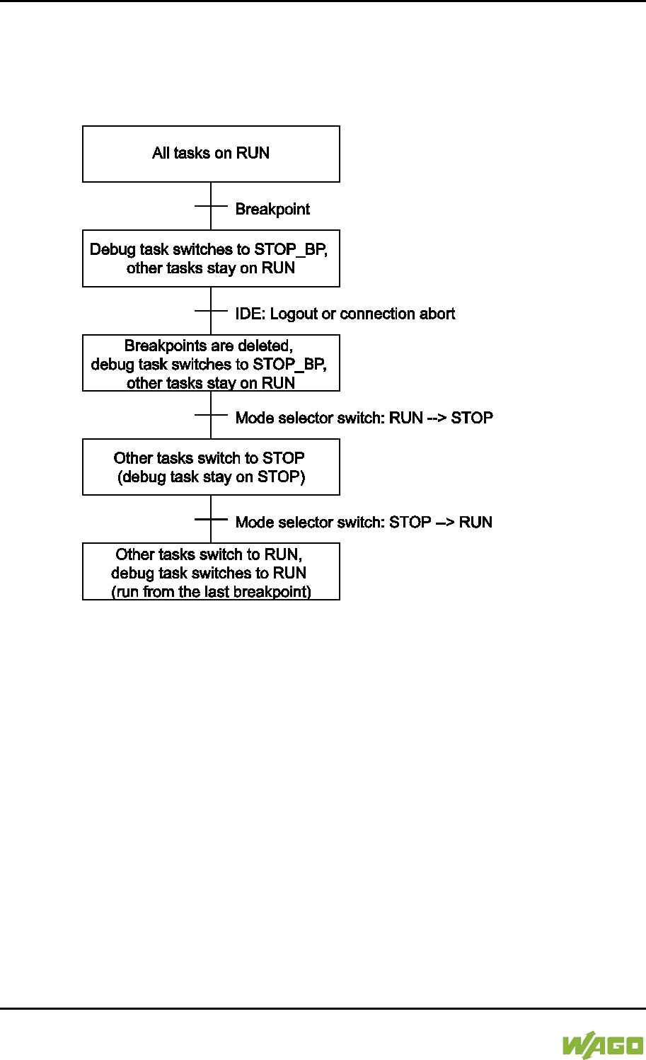
244 Run-time System CODESYS 2.3 WAGO-I/O-SYSTEM 750
750-8207 PFC200 CS 2ETH RS 3G
Manual
Draft version 1.2.1 from 2017-09-13, valid from FW Version 02.06.20(09)
If a task is at a breakpoint and the connection to the IDE is broken (e.g., by
logging out), all breakpoints are deleted.
The debug task stays at the current position until the next time the mode selector
switch is switched from STOP to RUN. In this case, the task continues to run
from the current position (case 7).
Figure 82: Debugging (Case 7)
8.5 System Events
Event tasks can be used in the CODESYS task configuration in addition to
cyclical tasks. Event tasks call up certain events in the device.
To activate events and define a program to be called up, open the window “Task
configuration” in the “Resources” tab in the CODESYS development
environment.
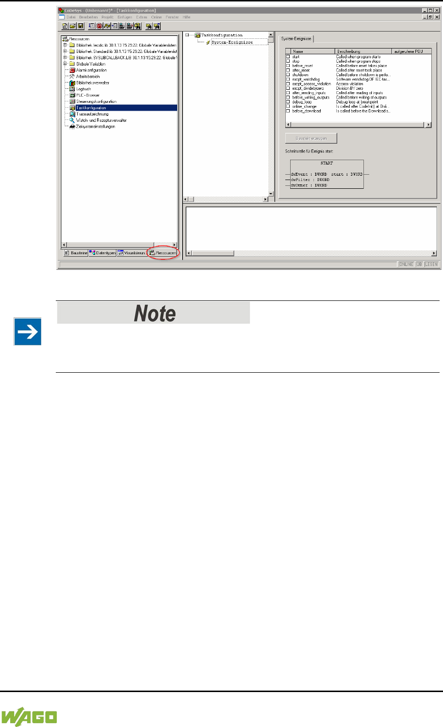
WAGO-I/O-SYSTEM 750 Run-time System CODESYS 2.3 245
750-8207 PFC200 CS 2ETH RS 3G
Manual
Draft version 1.2.1 from 2017-09-13, valid from FW Version 02.06.20(09)
Figure 83: CODESYS – System Events
Do not set debug points in the event handlers!
Debug points in event handlers can lead to unforeseeable errors and must
therefore not be set!
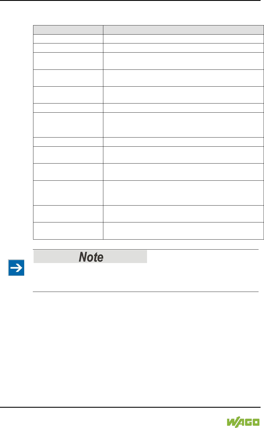
246 Run-time System CODESYS 2.3 WAGO-I/O-SYSTEM 750
750-8207 PFC200 CS 2ETH RS 3G
Manual
Draft version 1.2.1 from 2017-09-13, valid from FW Version 02.06.20(09)
The following events can be activated:
Table 191: Events
Name
Description
start
The event is called directly after the user program starts.
stop
The event is called directly after the user program stops.
before_reset
The event is called directly before the user program is
reset.
after_reset
The event is called directly after the user program is
reset.
shutdown
The event is called directly before the user program is
shutdown.
excpt_watchdog
The event is called if a task watchdog is recognized.
excpt_access_violation
The event is called if a memory access error to an
invalid memory area is recognized. (incorrect pointer,
invalid array index, invalid data descriptor)
excpt_dividebyzero
The event is called if a division by zero is recognized.
after_reading_inputs
The event is triggered after reading all of the inputs
independent of the user program.
before_writing_outputs
The event is triggered before writing all of the outputs
independent of the user program.
debug_loop
This event is triggered at every task call, if a breakpoint
was reached in this task and the processing of this task
is therefore blocked.
online_change
This event is called up after initialization of the program
on an online change.
before_download
This event is always called up before a download from
the IDE to the device takes place.
Application stops on a non-defined event handler!
If “excpt” events occur in the system and an event handler has not been defined,
the application goes into the “Stop” status.
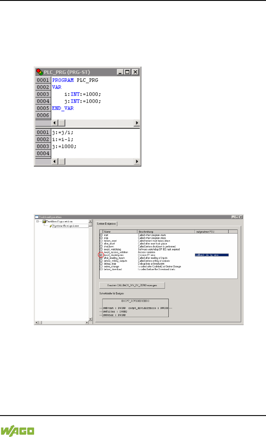
WAGO-I/O-SYSTEM 750 Run-time System CODESYS 2.3 247
750-8207 PFC200 CS 2ETH RS 3G
Manual
Draft version 1.2.1 from 2017-09-13, valid from FW Version 02.06.20(09)
8.5.1 Creating an Event Handler
The example here is provided to illustrate how to define and use an event
handler. The event handler “excpt_dividebyzero” is used in this example.
First, a program is generated in the PLC_PRG- module which provokes division
by 0.
Figure 84: CODESYS Program Provokes Division by “0”
After this, the system event “excpt_dividebyzero” is activated in the Task
Configurator and the name of the event handler to be generated is entered in the
column “Called POU”.
Figure 85: CODESYS – Creating and Activating an Event Handler
To generate the event handler, click [Generate CALLBACK_DIV_BY_ZERO
function block].
A new function having the defined name then appears in the “Function blocks”
tab.
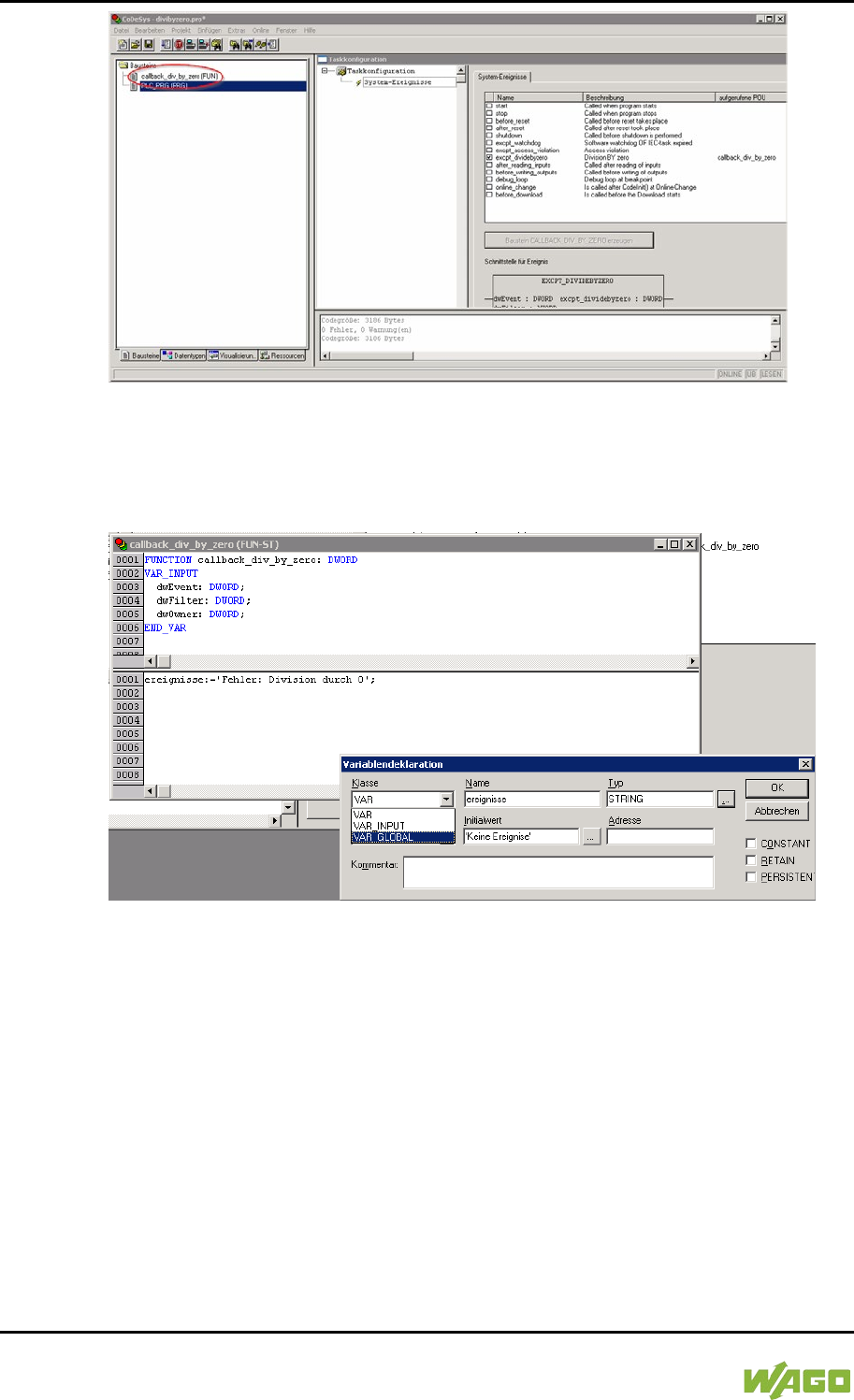
248 Run-time System CODESYS 2.3 WAGO-I/O-SYSTEM 750
750-8207 PFC200 CS 2ETH RS 3G
Manual
Draft version 1.2.1 from 2017-09-13, valid from FW Version 02.06.20(09)
Figure 86: CODESYS – New Module has been Generated
Handling for the event that has occurred is now programmed in this new function.
In the example here, the event is documented in a global variable.
Figure 87: CODESYS – Enter the Event in a Global Variable
The newly created project is now supported and can be loaded to the controller.
After startup, the value of the “Events” variable changes only when counter “i”
reaches the value 0, meaning that division by 0 has been performed.
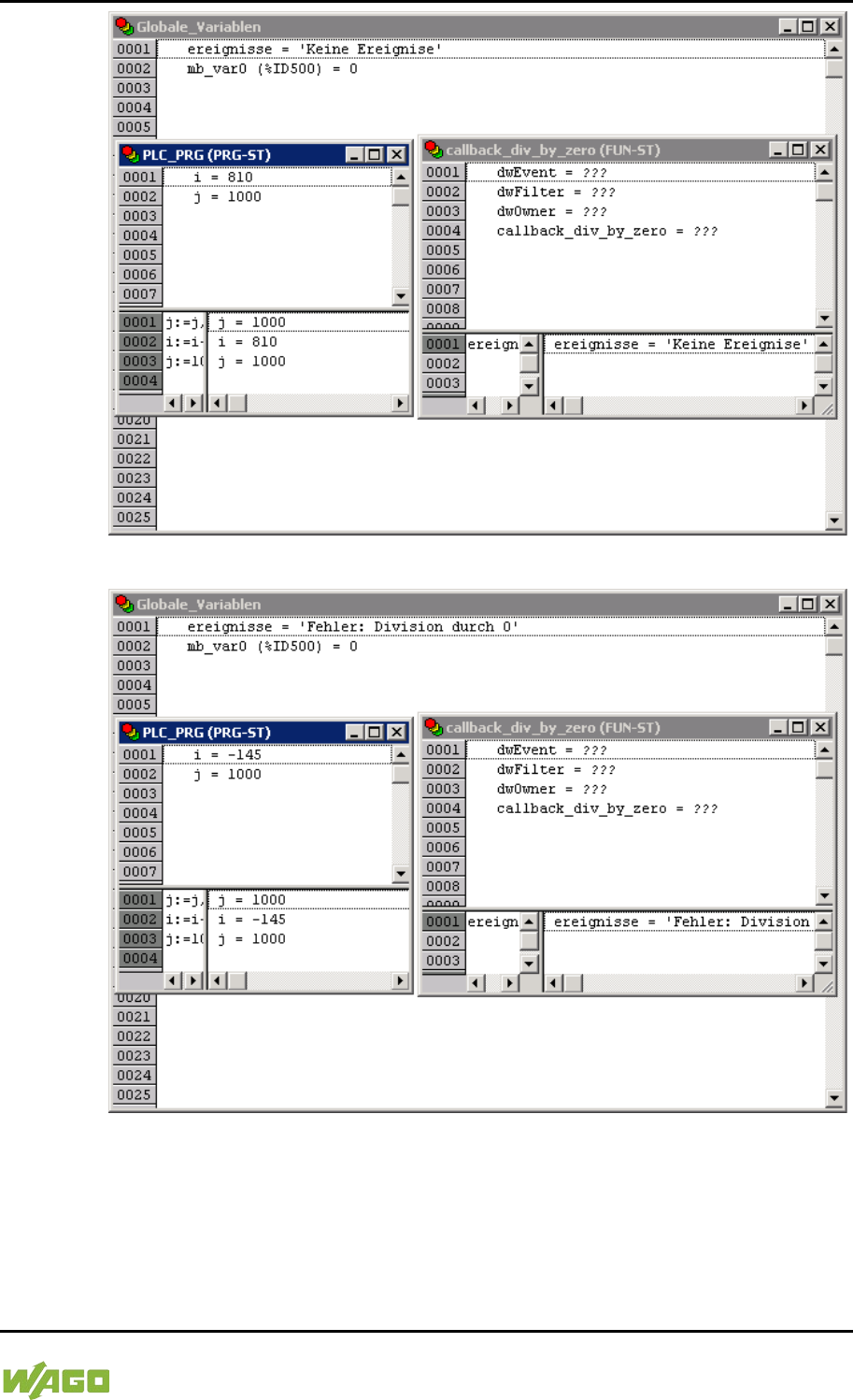
WAGO-I/O-SYSTEM 750 Run-time System CODESYS 2.3 249
750-8207 PFC200 CS 2ETH RS 3G
Manual
Draft version 1.2.1 from 2017-09-13, valid from FW Version 02.06.20(09)
Figure 88: CODESYS – Variable Contents Prior to Division by “0”
Figure 89: CODESYS – Variable Contents After Division by “0” and Call-up of the Event Handler
8.6 Process Images
A process image is a memory area in which the process data is stored in a
defined sequence and consists of the I/O modules attached to the internal bus,
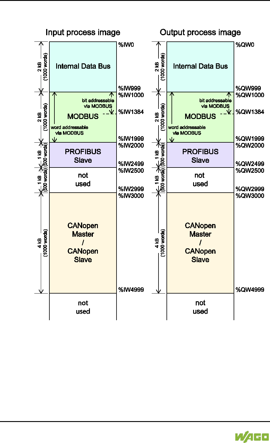
250 Run-time System CODESYS 2.3 WAGO-I/O-SYSTEM 750
750-8207 PFC200 CS 2ETH RS 3G
Manual
Draft version 1.2.1 from 2017-09-13, valid from FW Version 02.06.20(09)
the PFC variables, the bit memory address area and the slaves attached to the
fieldbus.
Figure 90: Process Image
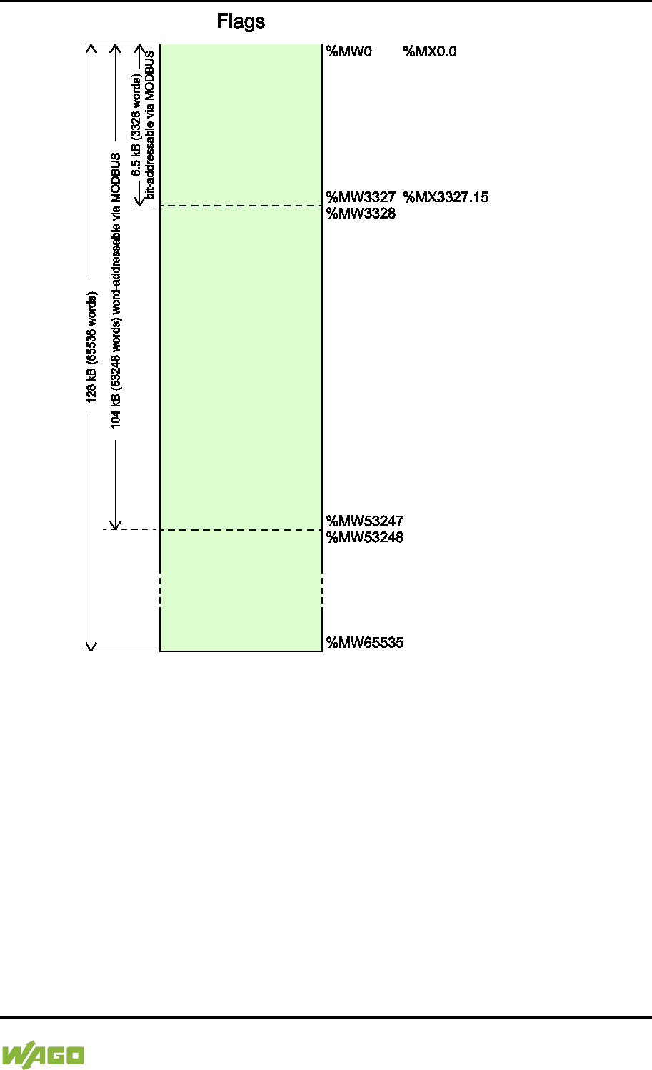
WAGO-I/O-SYSTEM 750 Run-time System CODESYS 2.3 251
750-8207 PFC200 CS 2ETH RS 3G
Manual
Draft version 1.2.1 from 2017-09-13, valid from FW Version 02.06.20(09)
Figure 91: Flag Area
8.6.1 Process Images for I/O Modules Connected to the
Controller
After starting the fieldbus controller, it automatically detects all connected I/O
modules.
The analog input and output data is stored first word by word in the process
image. Subsequent to this, come the digital input and output data bits combined
to form words.
The size and structure of the process image for the I/O modules connected to the
system are described in the appendix.
252 Run-time System CODESYS 2.3 WAGO-I/O-SYSTEM 750
750-8207 PFC200 CS 2ETH RS 3G
Manual
Draft version 1.2.1 from 2017-09-13, valid from FW Version 02.06.20(09)
I/O Module Data Width
The data width of an I/O module is between 0 and 48 bytes.
I/O Module Process Data
Check the I/O module process data whenever you add or remove the modules
to/from the fieldbus controller. Changing the I/O module topology results in an
adjustment of the process image, as the process data addresses also change.
8.6.2 Process Image for Slaves Connected to the Fieldbus
The size and structure of the process image for the slaves connected to the
system are described in the section for the specific fieldbus.
No direct access from fieldbus to the process image for I/O modules!
Any data that is required from the I/O module process image must be explicitly
mapped in the CODESYS program to the data in the fieldbus process image and
vice versa! Direct access is not possible!
8.7 Access to Process Images of the Input and Output
Data via CODESYS 2.3
The following tables describe the possibilities with which you can access the
address ranges of the process image for the inputs and outputs connected to the
internal data bus.
Table 192: Access to the Process Images of the Input and Output Data – Internal Data Bus
Memory area
Description
Access via
PLC
Logical Address Space
Internal data bus
input process
image
Map of the local input modules
(internal data bus, I/O module 1
to 1 bis 64*) in the RAM.
Read
Word
%IW0 to %IW999
Byte
%IB0 to %IB1999
Internal data bus
output process
image
Map of local output modules
(internal data bus, I/O module 1
to 64*) in the RAM.
Read/
Write
Word
%QW0 to %QW999
Byte
%QB0 to %QB1999
* The use of up to 250 I/O modules is possible with the WAGO internal data bus extension modules.
WAGO-I/O-SYSTEM 750 Run-time System CODESYS 2.3 253
750-8207 PFC200 CS 2ETH RS 3G
Manual
Draft version 1.2.1 from 2017-09-13, valid from FW Version 02.06.20(09)
Table 193: Access to the Process Images of the Input and Output Data – MODBUS
Memory area
Description
Access via
PLC
Logical Address Space
MODBUS input
process image
MODBUS input variables,
addressed by word via MODBUS
Read
Word
%IW1000 to %IW1999
Byte
%IB2000 to %IB3999
MODBUS input variables,
addressed by bit via MODBUS
Read
Bit
%IX1000.0 …%IX1000.15 to
%IX1384.0 … %IX1384.15
MODBUS output
process image
MODBUS output variables,
addressed by word via MODBUS
Read/
Write
Word
%QW1000 to %QW1999
Byte
%QB2000 to %QB3999
MODBUS output variables,
addressed by bit via MODBUS
Read/
Write
Bit
%QX1000.0 …
%QX1000.15 to %QX1384.0
… %QX1384.15
Table 194: Access to the Process Images of the Input and Output Data – CANopen
Memory area
Description
Access via
PLC
Logical Address Space
CANopen input
process image
CANopen master or CANopen
slave input variables
Read
Word
%IW3000 to %IW4999
Byte
%IB6000 to %IB9999
CANopen output
process image
CANopen master or CANopen
slave output variables
Read/
Write
Word
%QW3000 to %QW4999
Byte
%QB6000 to %QB9999
Table 195: Access to the Process Images of the Input and Output Data – PROFIBUS
Memory area
Description
Access via
PLC
Logical Address Space
PROFIBUS input
process image
PROFIBUS input variables
Read
Word
%IW2000 to %IW2499
Byte
%IB4000 to %IB4999
PROFIBUS
output process
image
PROFIBUS output variables
Read/
Write
Word
%QW2000 to %QW2499
Byte
%QB4000 to %QB4999

254 Run-time System CODESYS 2.3 WAGO-I/O-SYSTEM 750
750-8207 PFC200 CS 2ETH RS 3G
Manual
Draft version 1.2.1 from 2017-09-13, valid from FW Version 02.06.20(09)
Table 196: Access to the Process Images of the Input and Output Data – Flags
Memory area
Description
Access via
PLC
Logical Address Space
Flag variables
Total of 128 kB remanent
memory (65536 words).
Read/
Write
%MW0 to
%MW65535
104 kB addressed by word via
MODBUS (53248 words)
Read/
Write
Word (MODBUS)
%MW0 to %MW3327
6.5 kB addressed by bit via
MODBUS (3328 words).
Read/
Write
Bit (MODBUS)
%MX0.0 … %MX0.15 to
%MX3327.0 …
%MX3327.15
Retain variables
Retain memory addressed by
symbols in the NVRAM: 128 kB
Read/
Write
-
* The use of up to 250 I/O modules is possible with the WAGO internal data bus extension modules.
The total size of the memory for flag and retain variables is 128 kB (131060
bytes). The size of these two sections can be customized as required, provided
the total (permissible) size is not exceeded.
If you are using bit-oriented addressing, remember that the basic address is
word-based. The bits are addressed from 0 to 15.
8.8 Addressing Example
The following addressing example clarifies the access to the process image:
Table 197: Arrangement of the I/O Modules for the Addressing Example
Fieldbus controller
750-
400
1
750-
554
2
750-
402
3
750-
504
4
750-
454
5
750-
650
6
750-
468
7
750-
600
8
Table 198: Addressing Example
I/O module
Input data
Output data
Description
Type
C*
750-400
1 %IX8.0
2DI, 24 V, 3 ms:
1. Digital input module with a data width of 2
bits. As the analog input modules already
occupy the first 8 words of the input process
image, the 2 bits occupy the lowest-value bits
of the 8th word.
2 %IX8.1
750-554
1 %QW0
2AO, 4 – 20 mA:
1. Analog output module with a data width of 2
words. This module occupies the first 2 words
in the output process image.
2 %QW1
750-402
1 %IX8.2
4DI, 24 V:
2. Digital input module with a data width of 4
bits. These are added to the 2 bits of the 750-
400 module and stored in the 8th word of the
input process image.
2 %IX8.3
3 %IX8.4
4 %IX8.5
750-504
1 %QX4.0
4DO, 24 V:
1. Digital output module with a data width of 4
bits. As the analog output module already
2 %QX4.1

WAGO-I/O-SYSTEM 750 Run-time System CODESYS 2.3 255
750-8207 PFC200 CS 2ETH RS 3G
Manual
Draft version 1.2.1 from 2017-09-13, valid from FW Version 02.06.20(09)
Table 198: Addressing Example
I/O module
Input data
Output data
Description
Type
C*
3 %QX4.2
occupies the first 4 words of the output
process image, the 4 bits occupy the lowest-
value bits of the 4th word.
4 %QX4.3
750-454
1 %IW0
2AI, 4 – 20 mA:
1. Analog input module with a data width of 2
words. This module occupies the first 2 words
in the input process image.
2 %IW1
750-650 1
%IW2 RS-232, C 9600/8/N/1:
The serial interface module is an analog input
and output module, which displays 2 words
both in the input process image and in the
output process image.
%IW3
%QW2
%QW3
750-468
1 %IW4 4AI, 0 – 10 V S.E:
2. Analog input module with a data width of 4
words. As the 750-454 and 750-650 analog
input and output modules already occupy the
first 4 words of the input process image, the 4
words of this I/O module are added behind the
others.
2 %IW5
3 %IW6
4 %IW7
750-600
End module
The passive 750-600 end module does not
transmit any data.
Analog input and output modules
Digital input and output modules
*C: Number of the input/output
8.9 Internal Data Bus Synchronization
The internal data bus cycle and the CODESYS task cycle are optimally
automatically synchronized: This depends on the number of I/O modules
connected and the fastest CODESYS task cycle set in the fieldbus controller. The
synchronization cases described below can therefore take place.
In this chapter, CODESYS task denotes only tasks within CODESYS that contain
an access to the internal data bus. Tasks that do not access the internal data bus
are not synchronized in the same way as described below. For this, see Section
“Creating Tasks.”
8.9.1 Case 1: CODESYS Task Interval Set Smaller than the I/O
Module Cycle
Execution of the CODESYS tasks is synchronized with internal data bus cycle
time.
The CODESYS task is processed in parallel to the internal data bus cycle. The
CODESYS task interval is extended to the internal data bus cycle time. This is
necessary so that each CODESYS task is started with new input data from the
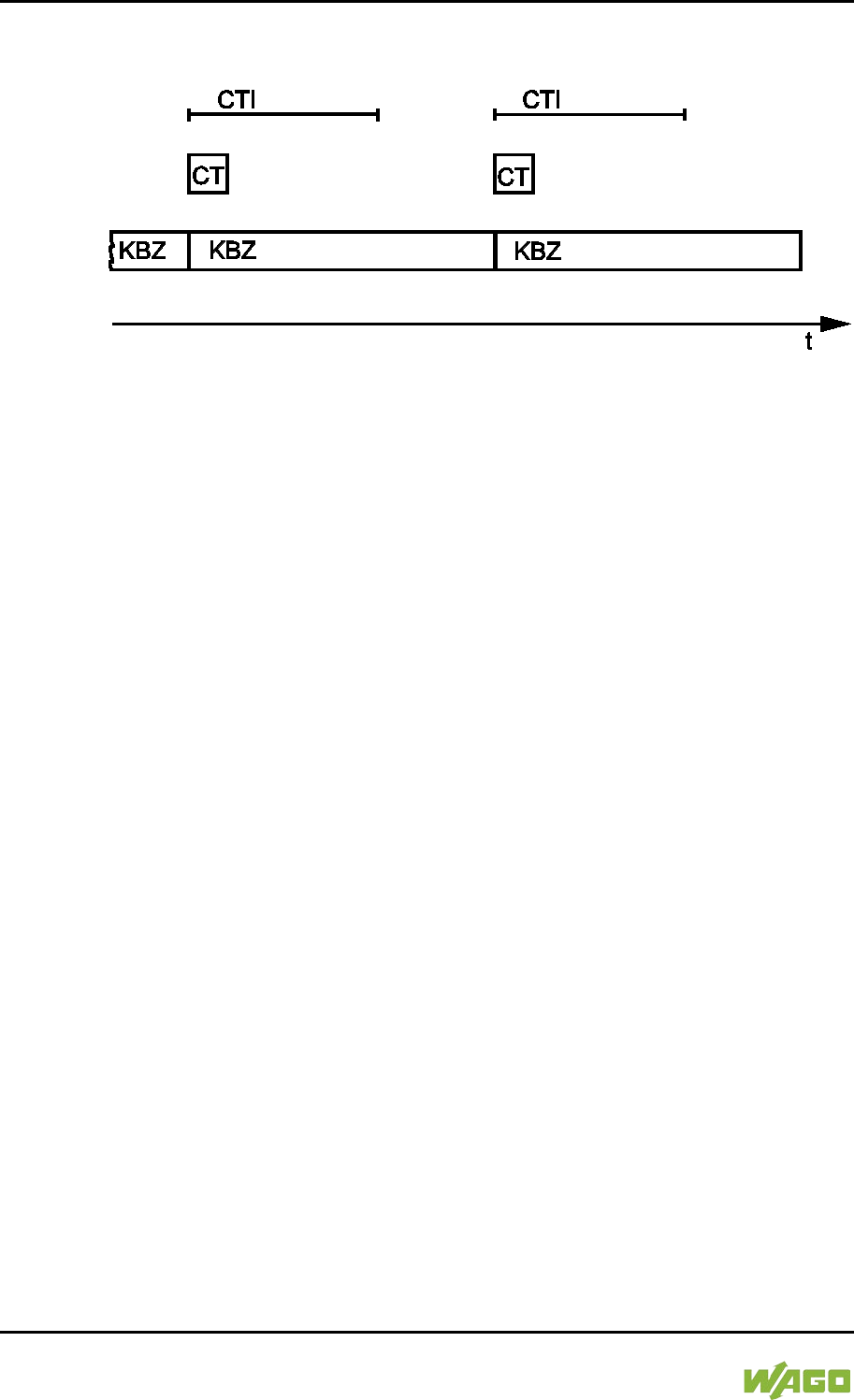
256 Run-time System CODESYS 2.3 WAGO-I/O-SYSTEM 750
750-8207 PFC200 CS 2ETH RS 3G
Manual
Draft version 1.2.1 from 2017-09-13, valid from FW Version 02.06.20(09)
internal data bus and the output values are also set at the module after each
CODESYS task.
Figure 92: Internal Data Bus Synchronization 01
CTI: CODESYS Task Interval
CT: CODESYS Task that accesses the I/O module of the internal data bus
KBZ: Internal Data Bus Cycle
Example:
CODESYS task interval (CTI): 100 µs
I/O module cycle (KBZ): 2000 µs
Result: Matching of the CODESYS task interval to the I/O module cycle of 2000
µs.
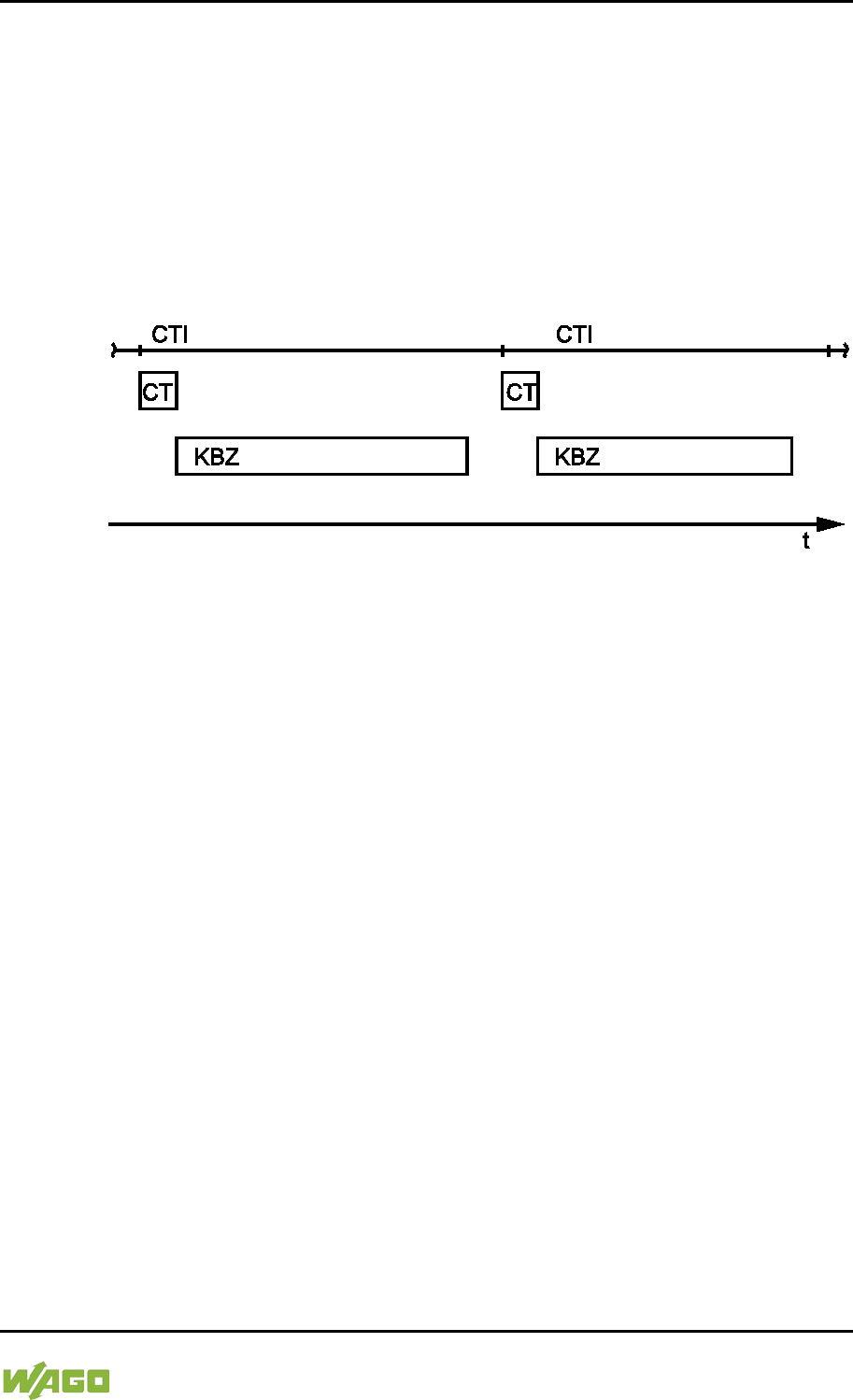
WAGO-I/O-SYSTEM 750 Run-time System CODESYS 2.3 257
750-8207 PFC200 CS 2ETH RS 3G
Manual
Draft version 1.2.1 from 2017-09-13, valid from FW Version 02.06.20(09)
8.9.2 Case 2: CODESYS Task Interval Smaller than Twice the
Internal Data Bus Cycle
Execution of the internal data bus is synchronized with the set CODESYS task
interval.
At the end of the CODESYS task, the internal bus cycle starts, which is
processed synchronously with the fastest CODESYS task. This ensures that
when starting each CODESYS Task, current input data are available from the
internal data bus and the output values of each CODESYS task are also output
to the I/O modules.
Figure 93: I/O Module Synchronization 02
CTI: CODESYS Task Interval
CT: CODESYS Task that accesses the I/O module of the internal data bus
KBZ: Internal Data Bus Cycle
Example:
CODESYS task interval (CTI): 2500 µs
Internal data bus cycle (KBZ): 2000 µs
Result: Execution of the internal data bus cycle every 2500 µs.

258 Run-time System CODESYS 2.3 WAGO-I/O-SYSTEM 750
750-8207 PFC200 CS 2ETH RS 3G
Manual
Draft version 1.2.1 from 2017-09-13, valid from FW Version 02.06.20(09)
8.9.3 Case 3: CODESYS Task Interval Greater than Twice the
Internal Data Bus Cycle
The I/O data from the internal data bus are refreshed once prior to the
CODESYS task and once after the CODESYS task.
Prior to processing the CODESYS task, the internal data bus cycle is executed,
which provides the current input data for the CODESYS task. After execution of
the CODESYS task, an additional internal data bus cycle is started, which
provides the output data to the I/O modules.
This ensures that at the start of every CODESYS task, current input data are
available from the internal data bus and the output data from each CODESYS
task are quickly output to the I/O modules. This prevents processing of internal
data bus cycles that would unnecessarily use a great deal of computing time on
the CPU.
Figure 94: I/O Module Synchronization 03
CTI: CODESYS Task Interval
CT: CODESYS Task that accesses the I/O module of the internal data bus
KBZ: Internal Data Bus Cycle
Example:
CODESYS task interval (CTI): 5000 µs
Internal data bus cycle (KBZ): 2000 µs
Result: Execution of the internal data bus cycle 2000 µs prior to the CODESYS
task and once directly after the CODESYS task.
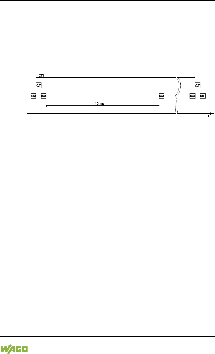
WAGO-I/O-SYSTEM 750 Run-time System CODESYS 2.3 259
750-8207 PFC200 CS 2ETH RS 3G
Manual
Draft version 1.2.1 from 2017-09-13, valid from FW Version 02.06.20(09)
8.9.4 Case 4: CODESYS Task Interval Greater than 10 ms
Synchronization takes place as in case 3; however, the output modules would be
reset to their default state after 150 ms without an internal data bus cycle. This
reliably prevents the execution of an internal data bus cycle after at least every
10 ms.
The I/O data from the internal data bus are refreshed once before the CODESYS
task and once after the CODESYS task and an additional internal data bus cycle
is also executed every 10 ms.
Figure 95: Internal Data Bus Synchronization 04
CTI: CODESYS Task Interval
CT: CODESYS task that accesses the I/O module of the internal data bus
KBZ: Internal data bus cycle
Example:
CODESYS task interval (CTI): 150000 µs
Internal data bus cycle (KBZ): 2000 µs
Result: Execution of the internal data bus cycle 2000 µs prior to the CODESYS
task, once directly after the CODESYS task and 10 ms after the previous internal
data bus cycle.
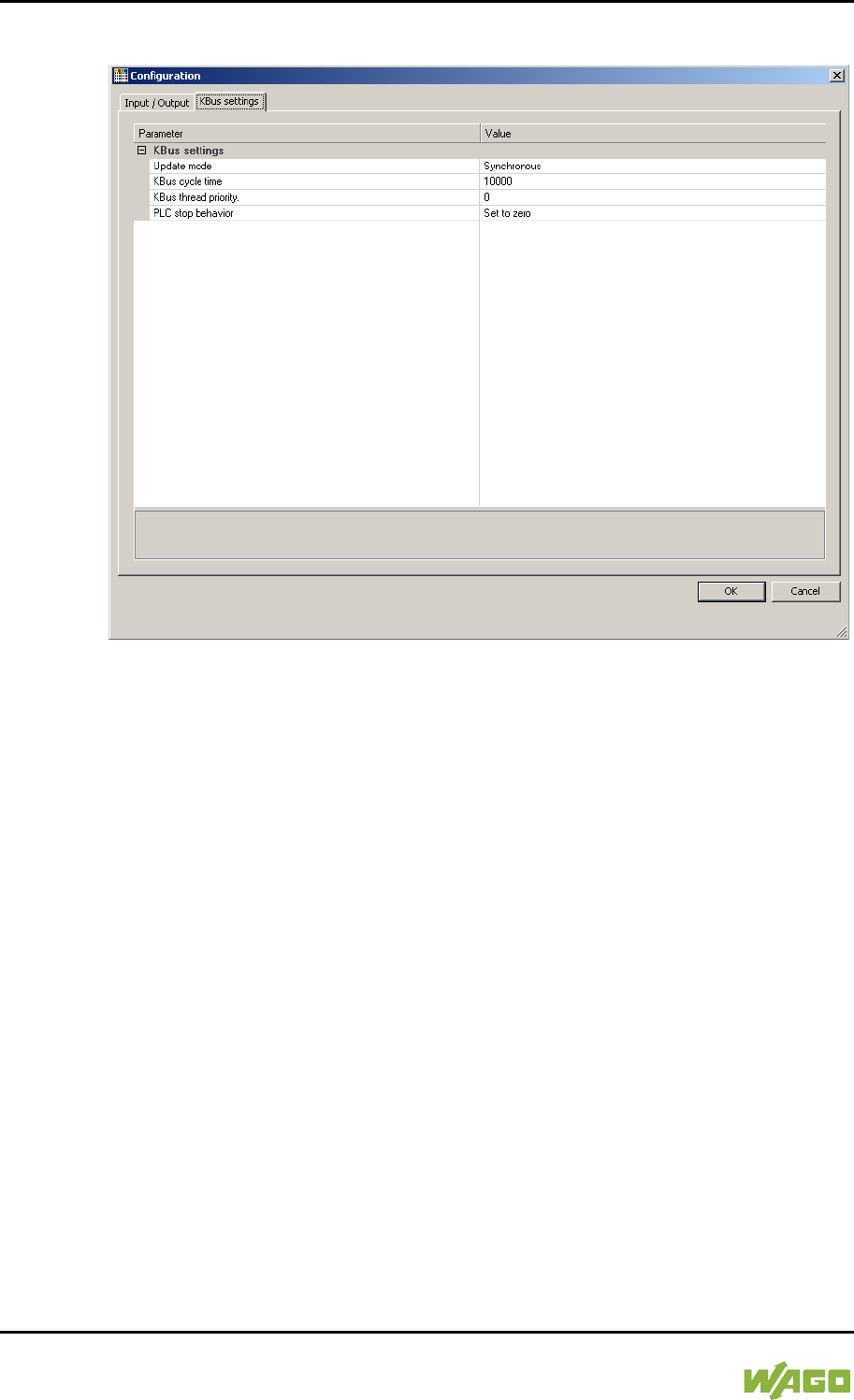
260 Run-time System CODESYS 2.3 WAGO-I/O-SYSTEM 750
750-8207 PFC200 CS 2ETH RS 3G
Manual
Draft version 1.2.1 from 2017-09-13, valid from FW Version 02.06.20(09)
8.9.5 Internal Data Bus Configuration
Figure 96: Internal Data Bus Settings
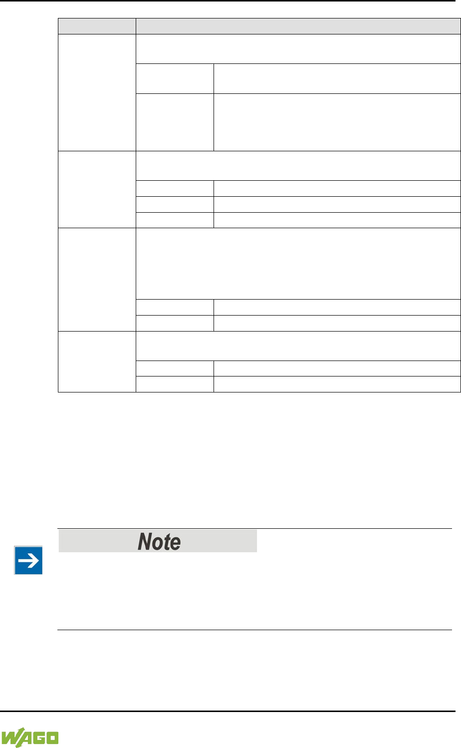
WAGO-I/O-SYSTEM 750 Run-time System CODESYS 2.3 261
750-8207 PFC200 CS 2ETH RS 3G
Manual
Draft version 1.2.1 from 2017-09-13, valid from FW Version 02.06.20(09)
Table 199: Internal Data Bus Settings
Parameter
Explanation
Update Mode
The Update mode is used to configure how the internal data bus
process data is to be updated (refreshed).
Asynchronous
In the asynchronous update mode process data
are refreshed in cycles at a definable interval.
Synchronous*
In the synchronous update mode the process
data are synchronized with the most rapid
CODESYS task that accesses the internal data
bus.
Internal Data
Bus Cycle
Time
The update interval for the internal data bus is set by the cycle
time. This setting is effective only in the asynchronous mode.
1000 µs
Minimum value 1 millisecond
10000 µs*
Default value 10 milliseconds
50000 µs
Maximum value 50 milliseconds
Internal Data
Bus Thread
Priority
This value indicates the priority for the internal data bus thread.
This setting is effective only in the asynchronous mode.
This priority is equivalent to the priority of the cyclic CODESYS
tasks (see Section “Cyclic Tasks”).
This setting is effective only in the asynchronous mode.
0*
Highest priority
15
Lowest priority
PLC stop
response
Specifies the response of the internal data bus outputs when the
PLC application stops.
Hold last value
The output states are retained.
Set to zero*
Outputs are set to zero.
* Default setting
8.9.5.1 Effect of Update Mode on CODESYS Tasks
8.9.5.1.1 Asynchronous Update Mode
In the asynchronous update mode there is no direct influence on CODESYS task
behavior.
Internal data bus “freeze” on priority conflicts!
In the asynchronous update mode there is a risk of the internal data bus
“freezing”, as the internal data bus thread operates at the same priority as the
IEC tasks. The internal data bus thread must therefore use a priority higher than
that of the IEC task to prevent this from occurring.

262 Run-time System CODESYS 2.3 WAGO-I/O-SYSTEM 750
750-8207 PFC200 CS 2ETH RS 3G
Manual
Draft version 1.2.1 from 2017-09-13, valid from FW Version 02.06.20(09)
8.9.5.1.2 Synchronous Update Mode
In the synchronous update mode the runtime behavior of CODESYS tasks can
be influenced by the internal data bus. The minimum task interval that can then
be achieved depends on the duration of an internal data bus cycle. The duration
of an internal data bus cycle, on the other hand, is based on the I/O modules
connected to the bus. As a rule of thumb: The shorter the internal data bus
structure, the shorter the cycle time and digital modules are faster than analog or
complex ones.
In the event of an internal data bus error, the CODESYS tasks are blocked until
the error is rectified, i.e., when an internal data bus cycle has been successfully
executed again.
No call-up of internal data bus status when internal data bus errors are
present!
If an internal data bus error has occurred, it is not possible to call up the internal
data bus status using KBUS_ERROR_INFORMATION (mod_com.lib) while in
the synchronous update mode.
8.10 Memory Settings in CODESYS
The list below illustrates the standard memory allocation of the PFC200:
• Program memory: 16 Mbyte (max.)
• Data memory: 64 Mbytes
• Input data: 64 kbytes
• Output data: 64 kbytes
• Flags: 24 kbytes
• Retain: 104 kbytes
• Function block limitation: 12 * 4096 bytes = 48 kbytes
8.10.1 Program Memory
The program memory (also code memory) cannot be configured and is limited to
a maximum of 16 Mbytes. The memory space actually available is based on the
scope of installed applications.
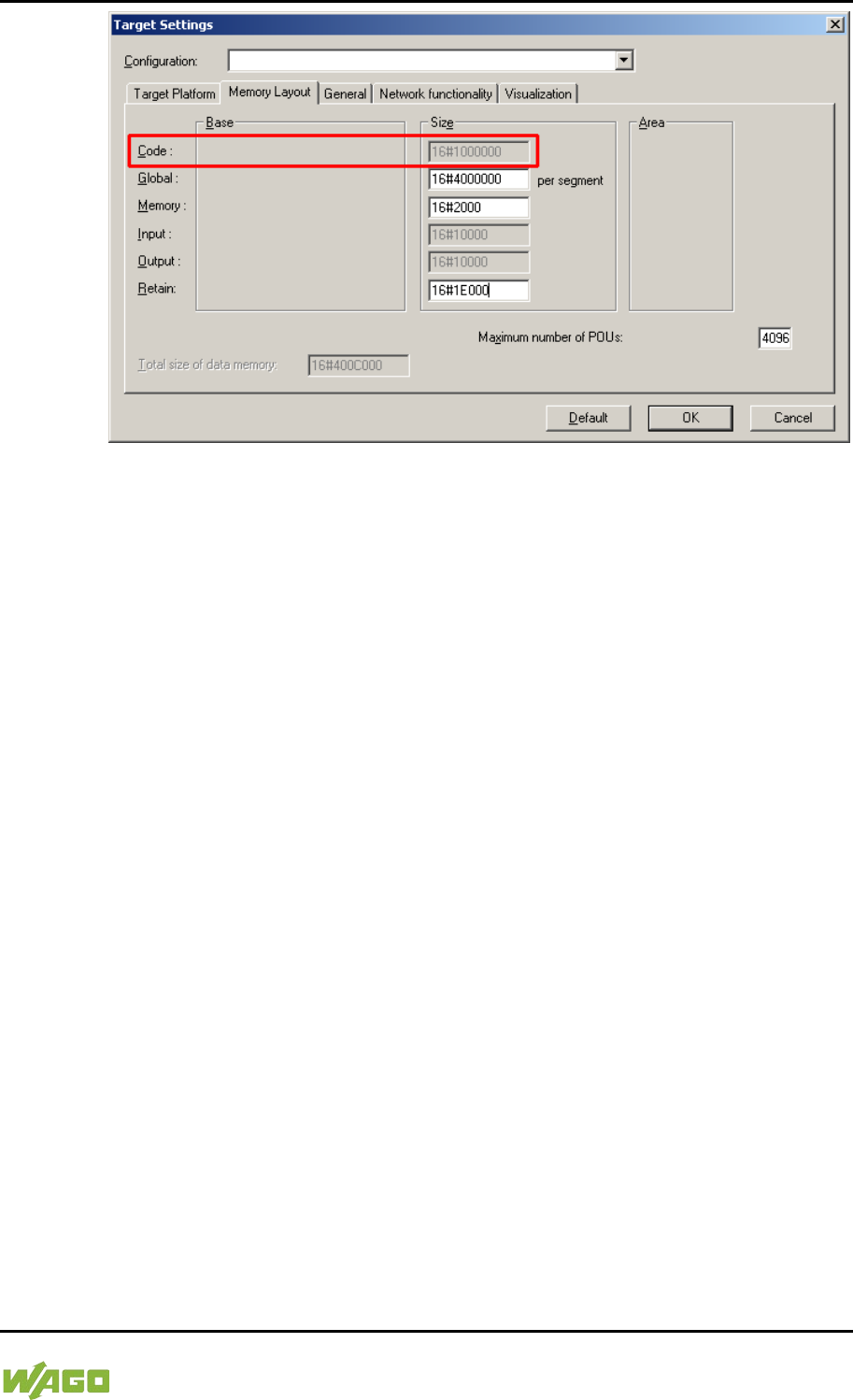
WAGO-I/O-SYSTEM 750 Run-time System CODESYS 2.3 263
750-8207 PFC200 CS 2ETH RS 3G
Manual
Draft version 1.2.1 from 2017-09-13, valid from FW Version 02.06.20(09)
Figure 97: Program Memory (Example)
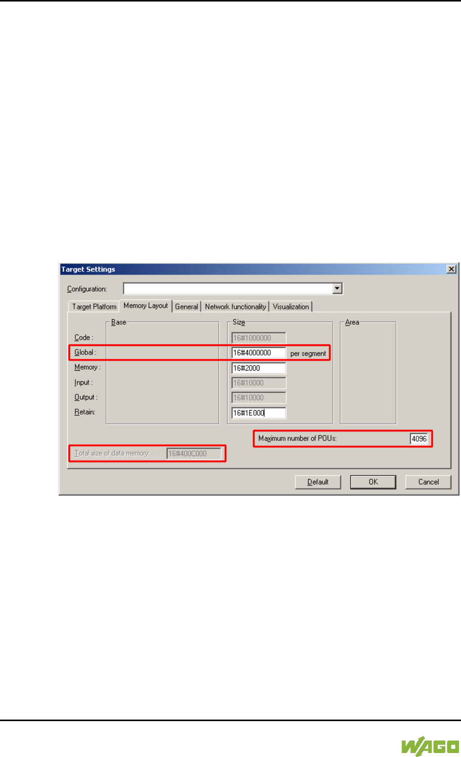
264 Run-time System CODESYS 2.3 WAGO-I/O-SYSTEM 750
750-8207 PFC200 CS 2ETH RS 3G
Manual
Draft version 1.2.1 from 2017-09-13, valid from FW Version 02.06.20(09)
8.10.2 Data Memory and Function Block Limitation
The data memory is set for 64 Mbytes in the controller's initial state.
This set value has already been requested in the system after a successful
program download and can be fully utilized.
Together with the data memory to be used by the application, memory is required
for the individual program function blocks in the system.
The size of the administration space is calculated from the function block
limitation * 12 (i.e., normally 4096 * 12).
The actual size of the main memory required in the system for data is the sum of
global data memory and function block limitation memory.
This value should not exceed the value specified for “Size of entire data
memory.”
Figure 98: Data Memory and Function Block Limitation (Example)
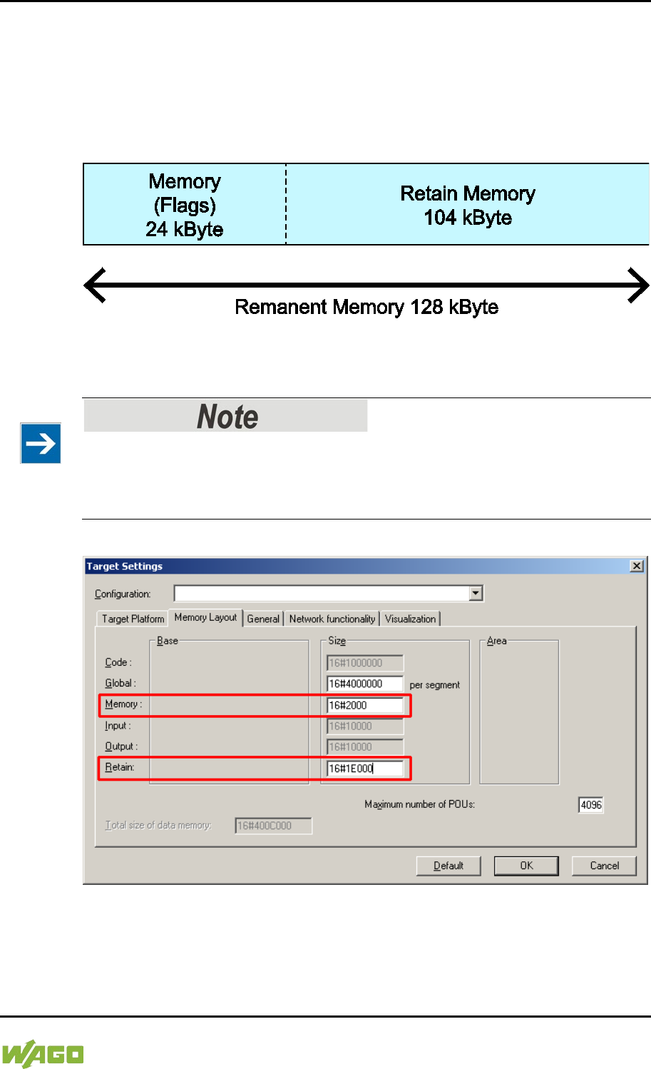
WAGO-I/O-SYSTEM 750 Run-time System CODESYS 2.3 265
750-8207 PFC200 CS 2ETH RS 3G
Manual
Draft version 1.2.1 from 2017-09-13, valid from FW Version 02.06.20(09)
8.10.3 Remanent Memory
A total of 128 kbytes of remanent memory is available for the IEC-61131
application.
The remanent section is subdivided into the flag area (memory) and the retain
area.
Figure 99: Remanent Main Memory (Example)
The breakdown of the flag and retain variables can be customized as required.
Observe general conditions!
The sum of Memory + Retain must not exceed the maximum value of 128 kbytes
(0x20000).
A maximum of 10,000 retain variables can be created.
Figure 100: Flag and Retain Memory (Example)
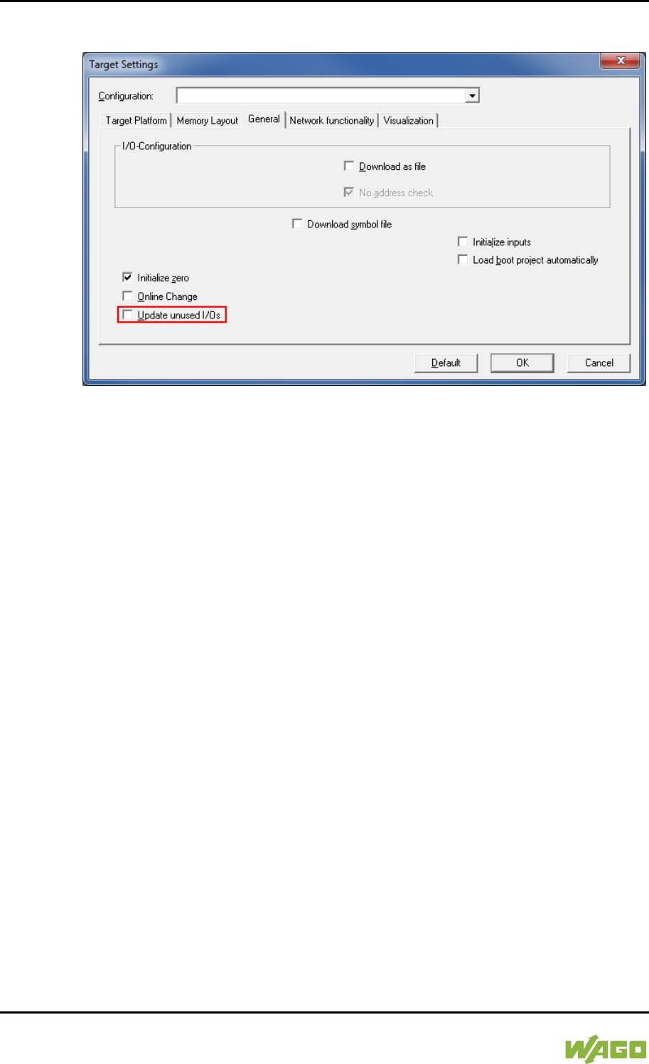
266 Run-time System CODESYS 2.3 WAGO-I/O-SYSTEM 750
750-8207 PFC200 CS 2ETH RS 3G
Manual
Draft version 1.2.1 from 2017-09-13, valid from FW Version 02.06.20(09)
8.11 General Target System Settings
Figure 101: General Target System Settings
No change to the settings is necessary on the “General” tab.
The “Update unused I/Os” box can be checked for initial startup. Enabling this
results in a higher CPU load and possibly a significant effect on task processing.
</dg_
8.12 CODESYS Visualization
CODESYS Web visualization is based on Java technology. All Java programs
require a Java runtime environment (JRE), which must be installed on the host
PC along with an Internet browser. An applet is stored in the file system of a Web
server and is accessible to browsers via an HTML page.
You create all visualization types (HMI and Web visualization) with the same
CODESYS graphic editor. Select the visualization type in the “Target system
settings” window. A description file in XML format is generated from the
information for each of these pages. You can find these files in the subfolder
“visu” of the CODESYS installation path. The HTML home page “webvisu.htm”
and the Java archive “webvisu.jar” in the applet (webvisu.class) are also saved
there in a compressed format.
Once you have selected a visualization type, the following steps must be
performed to execute the technique:
1. Click the “Resources” tab and open the “Target system settings.” Specify
whether you wish to have visualization displayed as a “Web visualization”
using an Internet browser.
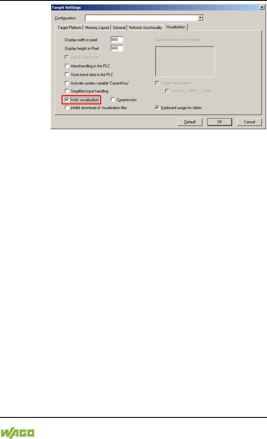
WAGO-I/O-SYSTEM 750 Run-time System CODESYS 2.3 267
750-8207 PFC200 CS 2ETH RS 3G
Manual
Draft version 1.2.1 from 2017-09-13, valid from FW Version 02.06.20(09)
Figure 102: Selecting the Visualization Technique in the Target System Settings
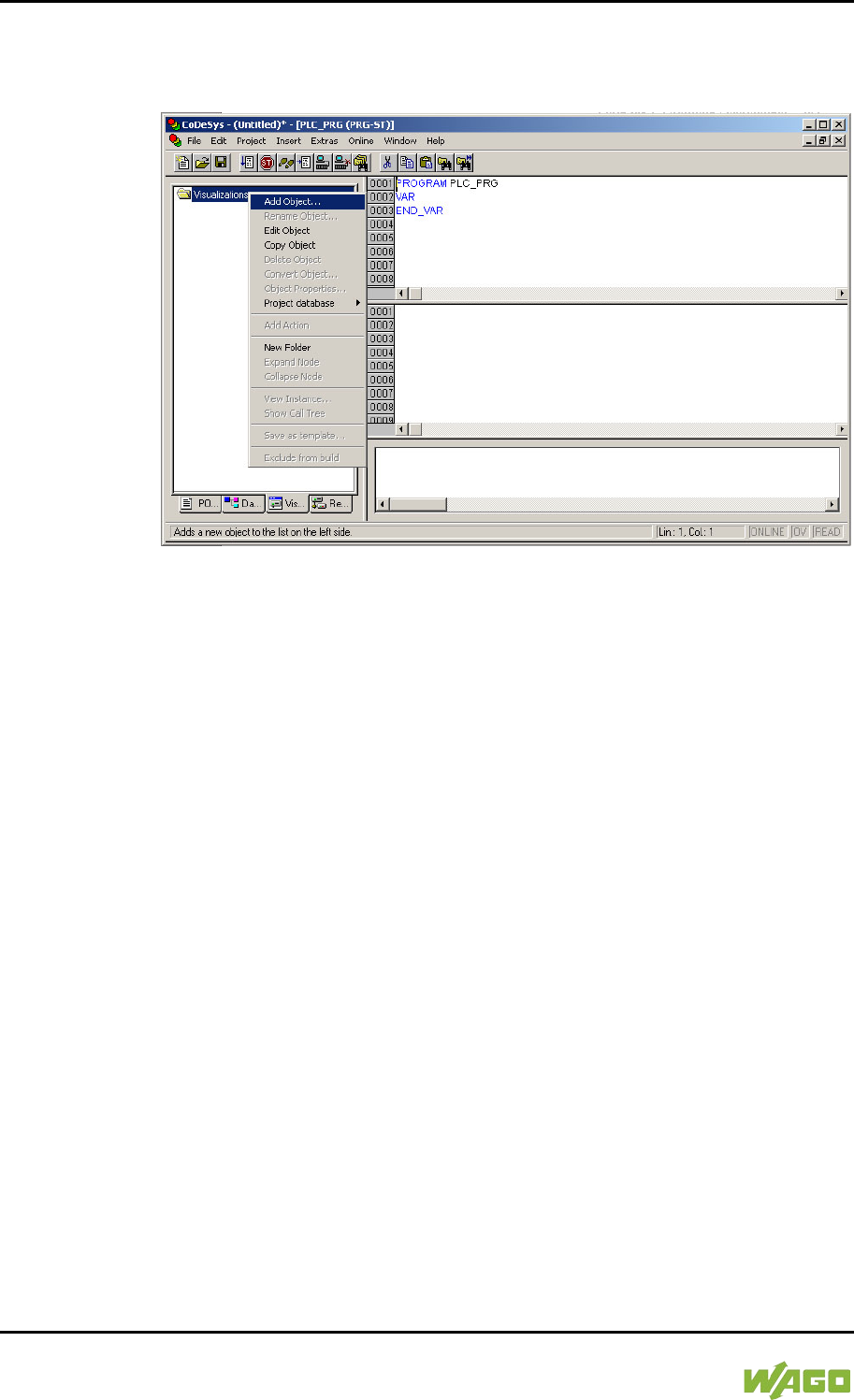
268 Run-time System CODESYS 2.3 WAGO-I/O-SYSTEM 750
750-8207 PFC200 CS 2ETH RS 3G
Manual
Draft version 1.2.1 from 2017-09-13, valid from FW Version 02.06.20(09)
2. Generate a start page for the visualization. Right-click the “Visualization”
folder in the “Visualization” tab. Select Add object ... from the contextual
menu. The “New visualization” dialog box opens.
Figure 103: Creating the PLC_VISU Starting Visualization
3. In the “New visualization” dialog window, enter the name PLC_VISU for the
start visualization. This page is then displayed as the start page upon
system startup.
4. Activate the CODESYS Web server in the WBM on the “Ports and Services
– CODESYS Services” page in the “CODESYS Webserver” group.
5. Activate the http service in the WBM on the “Ports and Services – Network
Services” page in the “HTTP” group.
If you transfer the PLC program to the controller (Online > Login) and start the
program (Online > Start), enter one of the following lines in the address line of
the Web browser for online visualization:
- “https://<IP address of the controller>/webvisu”, preferred method (http can
also be used instead of https)
- “https://<IP address of the controller>”, if the default Web server in the
WBM has been set to“WebVisu” (http can also be used instead of https)
- “http://<IP address of the controller>:8080/webvisu.htm”
You can also have Web visualization displayed via the WBM (see Section
“`CODESYS - WebVisu´” Page).

WAGO-I/O-SYSTEM 750 Run-time System CODESYS 2.3 269
750-8207 PFC200 CS 2ETH RS 3G
Manual
Draft version 1.2.1 from 2017-09-13, valid from FW Version 02.06.20(09)
Frequently Asked Questions
Additional information (FAQs) on CODESYS Web visualization is also provided
in the Section “Frequently Asked Questions about CODESYS Web Visualization”
and in the online Help function for CODESYS 2.3.
8.12.1 Limits of CODESYS Visualization
The controller supports the “WebVisu” visualization type integrated into
CODESYS. Technological limitations can be caused by the visualization type
used.
Compared to “HMI”, Web visualization on the controller is performed within
significantly narrower physical limits. Whereas “HMI” can access almost unlimited
resources on a desktop PC, the following limitations must be observed when
using Web visualization:
Adapting to the File System
The overall size of the PLC program, visualization files, bitmaps, log files,
configuration files, etc. must fit into the file system.
Process Data Memory
Web visualization uses its own protocol for exchanging process data between
applet and control.
The controller transfers process data with ASCII coding. The pipe symbol (“|”) is
used to separate two process values. Therefore, the space requirement for a
process data variable in the process data memory is dependent not only on the
data type, but also on the process value itself. Thus, a variable of the “WORD”
type occupies between one byte for the values 0 through 9 and five bytes for
values from 10000 and greater. The selected format (ASCII + |) only permits a
rough estimate of the space requirement for the individual process data in the
process data buffer. If the size of the ASCII coded process data is exceeded,
Web visualization no longer works as expected.
Computer Performance/Processor Time
The controller is based on a real-time operating system. This means that high-
priority processes (e.g., PLC program) interrupt or block lower priority processes.
The Web server responsible for Web visualization is among these lower priority
processes.

270 Run-time System CODESYS 2.3 WAGO-I/O-SYSTEM 750
750-8207 PFC200 CS 2ETH RS 3G
Manual
Draft version 1.2.1 from 2017-09-13, valid from FW Version 02.06.20(09)
Processor Time
Make sure when configuring tasks, that there is sufficient processor time
available for all processes.
Network Load
The controller's CPU processes both the PLC program and network traffic.
ETHERNET communication demands that each received telegram is processed,
regardless of whether it is intended for the controller or not.
A significant reduction of the network load can be achieved by using switches
instead of hubs.
There is no measure against broadcast telegrams that can be used on the
controller, however. These can only be curtailed by the sender, or blocked with
configurable switches that have a broadcast limitation. A network monitor such as
“wireshark” (www.wireshark.com) provides an overview of the current load in your
network.

WAGO-I/O-SYSTEM 750 Run-time System CODESYS 2.3 271
750-8207 PFC200 CS 2ETH RS 3G
Manual
Draft version 1.2.1 from 2017-09-13, valid from FW Version 02.06.20(09)
8.12.2 Eliminating Errors in CODESYS Web Visualization
If you are experiencing problems when working with the CODESYS Web
visualization, use the following table to find the solution. If you cannot eliminate
the problem, please contact WAGO support.
Table 200: Errors and Remedies
Error
Solution
Internet Explorer reports
the error “APPLET NOT
INITIATED”
Close all Internet Explorer windows and restart. If the error persists, this
indicates a missing or damaged file.
Using FTP, check if the entire Java archive “webvisu.jar” is available in
the “/PLC” folder of the controller. The original file can be found in the
installation path of CODESYS (usually under C:\Programme\WAGO
Software\CODESYS V2.3\Visu\webvisu.jar).
If necessary, replace the damaged file using FTP or force the download
of all files in CODESYS with Purge All > Compile All > Log in.
Web visualization is not
displayed
Have you installed the JRE? Check the firewall settings, e.g., if port 8080
is open.
Web visualization
“freezes”.
Web visualization stops
after an extended period
of time.
The call-up intervals selected in the task configuration are too small. As a
result, the Web server of the controller — which is executed with a low
priority — does not receive sufficient computer time, if any at all.
If no (explicit) task configuration has been provided, the PLC_PRG is
(implicitly) executed as a free running task with Priority 1. This
significantly limits the Web server’s computing time. Always provide a
task configuration when using Web visualization. In doing so, the call-up
interval should not exceed three times the average execution time.
When determining the execution time, ensure that the PLC program has
reached a “steady state.” When determining the execution time, ensure
that the PLC program is not “steady state.”
Web visualization
cannot be loaded into
the controller
Not all files may fit into the controller's file system. Delete any unneeded
data (e.g., via FTP).
Bitmap is not displayed
If the name of an image file contains umlauts, the Web server cannot
interpret these image names.
Java console reports:
“Class not found”
The JRE does not find the entry point for the class “webvisu.class” in the
Java archive “WebVisu.jar”. The Java archive is probably incomplete.
Delete “WebVisu.jar” from the Java cache and/or deactivate the cache.
In this case, the controller requests the archive (applet) again. If the
problem persists, reload the project into the controller.
Web visualization is
static, all process values
are “0”
Process data communication has failed.
If Web visualization is operated over a proxy server, then a SOCKS
proxy is also necessary for process data exchange in addition to the
actual HTTP proxy.

272 Run-time System CODESYS 2.3 WAGO-I/O-SYSTEM 750
750-8207 PFC200 CS 2ETH RS 3G
Manual
Draft version 1.2.1 from 2017-09-13, valid from FW Version 02.06.20(09)
8.12.3 FAQs about CODESYS Web Visualization
How can I optimize the applet for special screen resolutions?
In order to optimize the Web visualization for display on a device with a fixed
resolution, proceed as follows:
In the “Target system settings”, enter the pixel width and height in the tab
“Visualization”. When the visualization is created, the visible area is highlighted in
gray. However, the actual pixel width and height of the Web visualization is
defined by the attributes “Height” and “Width” of the HTML APPLET tag in the
“webvisu.htm” file. Do not forget to also adapt these parameters to the existing
resolution.
Which JRE should I use?
Java2 standard edition Version 1.5.0 (J2SE1.5.0_06) or higher is recommended.
This is available free of charge at www.oracle.com.
Microsoft's MSJVM3810 was also tested. For PDAs, there are runtime
environments available from other manufacturers (JamaicaVM, CrEme, etc.).
Please consider that for the Web visualization, these solutions can behave
differently within their scope of services (e.g., stability) than those mentioned
above.
Should the Java Cache be used?
This depends on the situation. After a standard installation, the cache is enabled.
If the cache is enabled, the JRE uses it to store applets and Java archives. If the
Web visualization is called up a second time, it requires considerably less time to
start because the applet (approx. 250 kb) does not need to be reloaded via the
network, but is already available in the cache. This is especially useful when
network connections are slow.
Note:
The Java archives may not be completely transferred into the cache due to
network failures. In this case, the cache must be cleared manually or disabled.

WAGO-I/O-SYSTEM 750 Run-time System CODESYS 2.3 273
750-8207 PFC200 CS 2ETH RS 3G
Manual
Draft version 1.2.1 from 2017-09-13, valid from FW Version 02.06.20(09)
Why does the visualization element “TREND” in the Web visualization only
work “Online”?
The following settings must be selected for visualization projects: Resources tab
> Target system settings.
Activate “Web visualization” and “Trend data recording within control”. Otherwise,
the trend data is stored on the hard drive of the CODESYS development PC.
This makes a permanent connection between the controller and the CODESYS
gateway necessary. If this connection is interrupted, this may lead to the
controller behaving unpredictably.
In the TREND configuration dialog, you can choose between “Online” and
“History” operating modes. The controller only supports the “Online” operating
mode for visualization projects since it is not possible to configure the maximum
size (quota) of the trend files (*.trd). Uncontrolled expansion of trend files can
lead to unpredictable controller behavior.
In most cases, the use of the “HISTOGRAM” visualization element is the better
choice, as this gives full control over the time and number of measurements and
thus the amount of memory required.
What needs to be observed when the visualization element “ALARM
TABLE” is used in the Web visualization?
The status of this component is best described as “Add-On”, i.e., an extra that is
free of charge and not warrantied.
The following settings must be selected for visualization projects: Resources tab
> Target system settings.
Activate “Web visualization” (checkmark) and “Alarm handling within control”.
Otherwise, the alarm data is processed on the CODESYS development PC. This
makes a permanent connection between the controller and the CODESYS
gateway necessary. If this connection is interrupted, this may lead to the
controller behaving unpredictably.

274 e!RUNTIME Runtime Environment WAGO-I/O-SYSTEM 750
750-8207 PFC200 CS 2ETH RS 3G
Manual
Draft version 1.2.1 from 2017-09-13, valid from FW Version 02.06.20(09)
9 e!RUNTIME Runtime Environment
9.1 General Notes
Additional Information
Information on the installation and startup of e!COCKPIT is provided in the
corresponding manual.
Information on programming is provided in the CODESYS 3 documentation.

WAGO-I/O-SYSTEM 750 e!RUNTIME Runtime Environment 275
750-8207 PFC200 CS 2ETH RS 3G
Manual
Draft version 1.2.1 from 2017-09-13, valid from FW Version 02.06.20(09)
9.2 CODESYS V3 Priorities
A list of priorities implemented for the controller is provided below as
supplementary information to the CODESYS 3 documentation.
Table 201: CODESYS V3 Priorities
Scheduler Task
Linux®
Priority
IEC
Priority
Remark
Preemptive
scheduling
-
Real-time
range
Local or
fieldbus - HIGH -95 … -86
Internal data bus (-88)
Mode selector
switch monitoring -85
Task registers changes
to the mode selector
switch and changes
the state of the PLC
application. (start, stop,
reset warm/cold)
CODESYS
watchdog
-83
Execution of the
watchdog functions
Cyclic and event-
controlled IEC task -55 … -53
1 … 3
For real-time tasks
which must not be
influenced in execution
by external interfaces
(e.g., fieldbus).
Local or
fieldbus - MID -52 … -43
CAN (-52 … -51)
Profibus (-49 … 45)
MODBUS slave/master
(-43)
Cyclic and event-
controlled IEC task -42 … -32
4 … 14
For real-time tasks
which must not
influence fieldbus
communication during
execution.
Local or fieldbus –
LOW
-13 … -4
Fair
scheduling
-
None real-
time range
CODESYS
communication Back-
ground
(20)
Communication with
the CODESYS
development
environment
Cyclic, event-
controlled and
freewheeling IEC
task
15
Incl. standard priority of
the visualization task
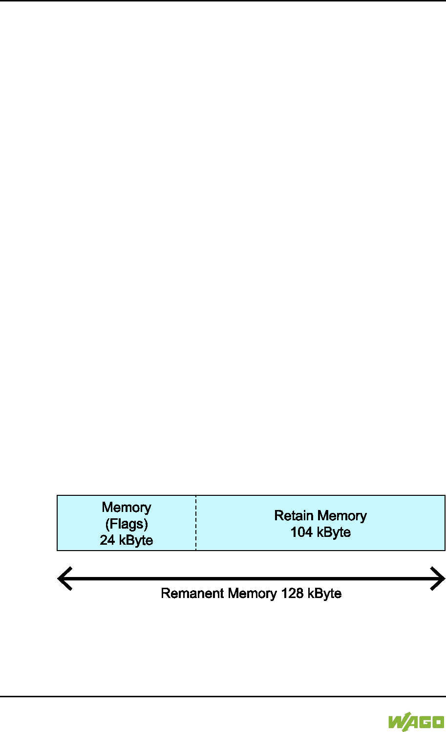
276 e!RUNTIME Runtime Environment WAGO-I/O-SYSTEM 750
750-8207 PFC200 CS 2ETH RS 3G
Manual
Draft version 1.2.1 from 2017-09-13, valid from FW Version 02.06.20(09)
9.3 Memory Spaces under e!RUNTIME
The memory spaces in the controller under e!RUNTIME have the following sizes:
• Program and data memory: 60 Mbytes
• Input data: 64 kbytes
• Output data: 64 kbytes
• Flags: 24 kbytes
• Retain: 104 kbytes
• Function block limitation: 12 * 4096 bytes = 48 kbytes
9.3.1 Program and Data Memory
The program (also code) and data memory has a size of 60 Mbytes.
This space has already been requested in the system after a successful program
download and can be fully utilized.
The memory space is dynamically divided up into program and data space.
9.3.2 Function Block Limitation
Together with the data memory to be used by the application, memory is required
for the individual program function blocks in the system.
The size of the administration space is calculated from the function block
limitation * 12 (i.e., 4096 * 12).
The actual size of the main memory required in the system for data is the sum of
global program and data memory and function block limitation memory.
9.3.3 Remanent Memory
A total of 128 kbytes of remanent memory is available for the IEC-61131
application.
The remanent section is subdivided into the flag area (memory) and the retain
area.
Figure 104: Remanent Main Memory

WAGO-I/O-SYSTEM 750 MODBUS – CODESYS 2 277
750-8207 PFC200 CS 2ETH RS 3G
Manual
Draft version 1.2.1 from 2017-09-13, valid from FW Version 02.06.20(09)
10 MODBUS – CODESYS 2
</dg_
10.1 General
MODBUS is a non-vendor-specific, open fieldbus standard for a wide range of
applications in production and process automation. The MODBUS
communications protocol is based on a master/slave or client/server architecture
that uses function codes for execution of individual MODBUS services, which
have reading or writing access to individual or multiple elements of the MODBUS
data model simultaneously.
10.2 Features
The MODBUS slave implemented in the PFC200 has the following features:
• 3 modes: MODBUS TCP, MODBUS UDP and MODBUS RTU, which can
be run independently of one another simultaneously
• Each mode can be configured
• 10 supported MODBUS services (Function Codes): FC1 to FC6, FC15,
FC16, FC22, FC23
• Data exchange via 1000 registers in each of the local MODBUS process
images
• 768-byte sector that can be addressed by bits in each local MODBUS
process image
• Access to a 104 kB flag sector (total of 53248 registers/words, with 3328
addressable bits)
• 28 Information and configuration registers
• Up to 1000 TCP connections
• MODBUS communications monitoring using programmable watchdogs
• Configurable response on PLC stop
• Configurable response on disruption of MODBUS communication
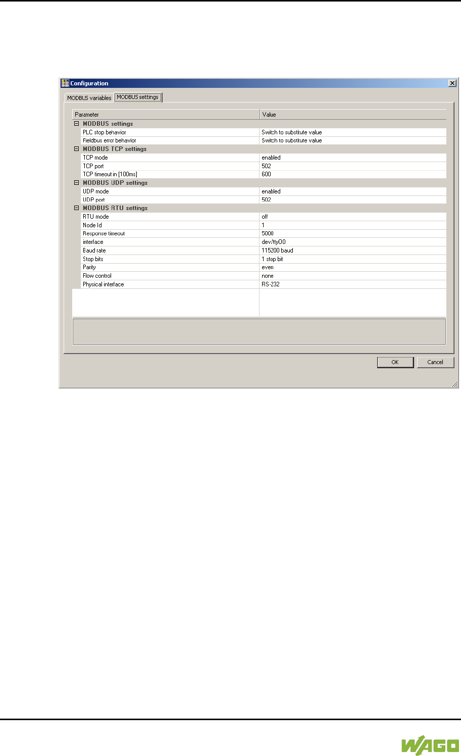
278 MODBUS – CODESYS 2 WAGO-I/O-SYSTEM 750
750-8207 PFC200 CS 2ETH RS 3G
Manual
Draft version 1.2.1 from 2017-09-13, valid from FW Version 02.06.20(09)
10.3 Configuration
All of the MODBUS operating modes are configured using the CODESYS PLC
configuration.
Figure 105: CODESYS PLC Configuration - MODBUS Settings
The MODBUS slave configuration is composed of four basic parameter groups:
• MODBUS settings,
• MODBUS TCP settings,
• MODBUS UDP settings,
• MODBUS RTU settings.
A detailed description of all the parameter groups is given in the following
sections.

WAGO-I/O-SYSTEM 750 MODBUS – CODESYS 2 279
750-8207 PFC200 CS 2ETH RS 3G
Manual
Draft version 1.2.1 from 2017-09-13, valid from FW Version 02.06.20(09)
10.3.1 MODBUS Settings
The “MODBUS settings” group contains the following configuration parameters.
Table 202: MODBUS Settings
Parameters
Explanation
PLC stop
behavior
Response of the MODBUS slave when the controller has halted
(controller in STOP state)
No data
exchange
No data exchange possible. MODBUS requests
will always be answered by the exception
response “ILLEGAL FUNCTION” (0x81).
Switch to
substitute
value*
Data exchange possible. Substitute values (0)
are provided for MODBUS read requests and the
values accepted unchanged in the local
MODBUS process image for write requests,
without passing these on to the controller.
Hold last value
Data exchange possible. The last frozen values
are provided for MODBUS read requests and the
values accepted unchanged in the MODBUS
process image for write requests, without passing
these on to the controller.
Fieldbus error
response
Response of the MODBUS slave to detected fieldbus errors
(interruption of communication).
No data
exchange
No data exchange possible.
Switch to
substitute
value*
Data exchange possible. Substitute values (0)
are supplied from the MODBUS process image
for PLC read functions; for write access the
values are accepted unchanged in the MODBUS
process image without passing them on to the
MODBUS master.
Hold last value
Data exchange possible. The previously frozen
values are supplied from the MODBUS process
image for PLC read functions; for write access
the values are accepted unchanged in the
MODBUS process image without passing them
on to the MODBUS master.
* Default setting
280 MODBUS – CODESYS 2 WAGO-I/O-SYSTEM 750
750-8207 PFC200 CS 2ETH RS 3G
Manual
Draft version 1.2.1 from 2017-09-13, valid from FW Version 02.06.20(09)
10.3.2 MODBUS TCP Settings
The “MODBUS TCP Settings” contains the following configuration parameters for
the “MODBUS TCP” mode:
Table 203: MODBUS TCP Settings
Parameters
Explanation
TCP mode
Enable for the MODBUS TCP mode
Off
Operation not permitted
Active*
Operation possible
TCP port
Port number for the TCP link
1
Minimum port number
502*
MODBUS default port
65535
Maximum port number
TCP Timeout
Time-out for a TCP link
1
100 ms (1 × 100 ms)
600*
60 seconds (600 × 100ms)
65535
1 h 49 min 13 s 500 ms (65535 × 100 ms)
* Default setting
10.3.3 MODBUS UDP Settings
The “MODBUS UDP Settings” group contains the following configuration
parameters for the “MODBUS UDP” mode:
Table 204: MODBUS UDP Settings
Parameters
Explanation
UDP mode
Enable for the MODBUS UDP mode
Off
Operation not permitted
Active*
Operation possible
UDP port
Port number for the UDP link
1
Minimum port number
502*
MODBUS default port
65535
Maximum port number
* Default setting
10.3.4 MODBUS RTU Settings
The “MODBUS RTU Settings” group contains the following configuration
parameters for the “MODBUS RTU” mode:

WAGO-I/O-SYSTEM 750 MODBUS – CODESYS 2 281
750-8207 PFC200 CS 2ETH RS 3G
Manual
Draft version 1.2.1 from 2017-09-13, valid from FW Version 02.06.20(09)
Table 205: MODBUS RTU Settings
Parameters
Explanation
RTU mode
Enable for the MODBUS RTU mode
Off*
Operation not permitted
Active
Operation possible
Device ID
Device ID (device address) for the tty device
1*
min. device ID
247
max. device ID
Maximum
response time
Response timeout for a request in [ms]
2000
min. response time = 2 seconds. If this value is
set lower than 2 seconds, it will be corrected
internally to 2 seconds.
5000*
Default = 5 seconds
4294967295
max. response time > 71 hours.
Interface
Device name
“dev/…”
Name of the tty in the string
“dev/ttyO0”*
Standard tty
Baud rate
Communication baud rate
1200 baud
1200 baud min. transmission speed
2400 baud
2400 baud
4800 baud
4800 baud
9600 baud
9600 baud
19200 baud
19200 baud
38400 baud
38400 baud
57600 baud
57600 baud
115200 baud*
115200 baud, max. transmission speed
Stop bits
Number of stop bits
1 stop bit*
1 stop bit in the frame; must be used when even
or odd parity has been selected.
2 stop bits
2 stop bits in the frame; must be used when
“None” has been selected for parity.
Parity
Parity check
None
No parity check performed; 2 stop bits must be
selected in the configuration for this setting.
Even*
Even parity
Odd
Odd parity

282 MODBUS – CODESYS 2 WAGO-I/O-SYSTEM 750
750-8207 PFC200 CS 2ETH RS 3G
Manual
Draft version 1.2.1 from 2017-09-13, valid from FW Version 02.06.20(09)
Table 205: MODBUS RTU Settings
Parameters
Explanation
Flow control
Data flow control (Supported only for the setting “RS-232” for the
physical interface.)
None*
No data flow control
RTS/CTS
Hardware flow control
Physical
interface
Mode for the physical interface
RS-232*
RS-232 is used as the physical interface.
RS-485
RS-485 is used as the physical interface.
* Default setting

WAGO-I/O-SYSTEM 750 MODBUS – CODESYS 2 283
750-8207 PFC200 CS 2ETH RS 3G
Manual
Draft version 1.2.1 from 2017-09-13, valid from FW Version 02.06.20(09)
</dg_
10.4 Data Exchange
MODBUS data exchange is performed in cycles or acyclically using MODBUS
services. The type and number of usable MODBUS services depends on the
area that is addressed. There are generally four MODBUS-relevant address
areas in the PFC200:
• MODBUS input process image (MODBUS Input) – is an area in the PIO
(PIO = Output Process Image), in which data from the PLC is provided in
cycles exclusively for MODBUS Read services.
• MODBUS output process image (MODBUS Output) – is an area in the PII
(PII = Input Process Image), in which MODBUS Write services provide data
for cyclic reading by the PLC. MODBUS Read services are also acceptable
in this area.
• MODBUS flag area – is an area, in which both MODBUS Read and Write
services can be executed.
• MODBUS register – is an area, in which the WAGO-specific information
and configuration registers are contained. Only MODBUS register services
may be executed in this area.
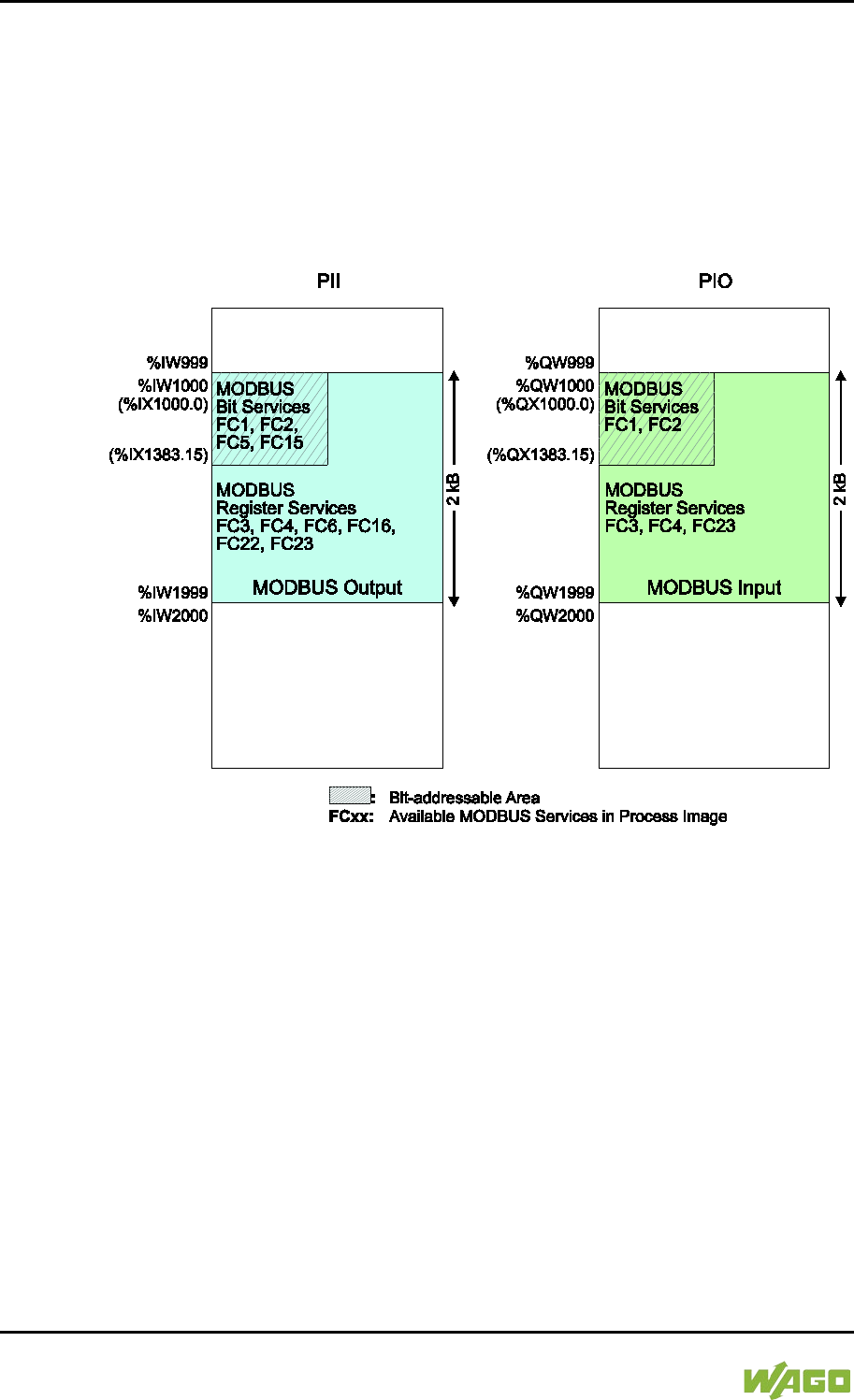
284 MODBUS – CODESYS 2 WAGO-I/O-SYSTEM 750
750-8207 PFC200 CS 2ETH RS 3G
Manual
Draft version 1.2.1 from 2017-09-13, valid from FW Version 02.06.20(09)
10.4.1 Process Image
The main data interfaces between the PLC and the MODBUS slave are the local
MODBUS process images in the PLC address area based on IEC 61131. The
MODBUS input process image (MODBUS Input) is in the PIO and the MODBUS
output process image (MODBUS Output) in the PII. Data memory blocks of 2 kB
(1000 registers/word) are available for each local MODBUS input and output
process image. The first 768 bytes of each of these data blocks are also provided
for executing bit services.
Figure 106: MODBUS Process Image
As no direct access to the I/O modules is provided by the fieldbus, data can be
exchanged via this interface between the PLC and MODBUS for processing in
the control system (PLC). Using this data in the individual I/O modules connected
to the PLC can then be performed by the application.
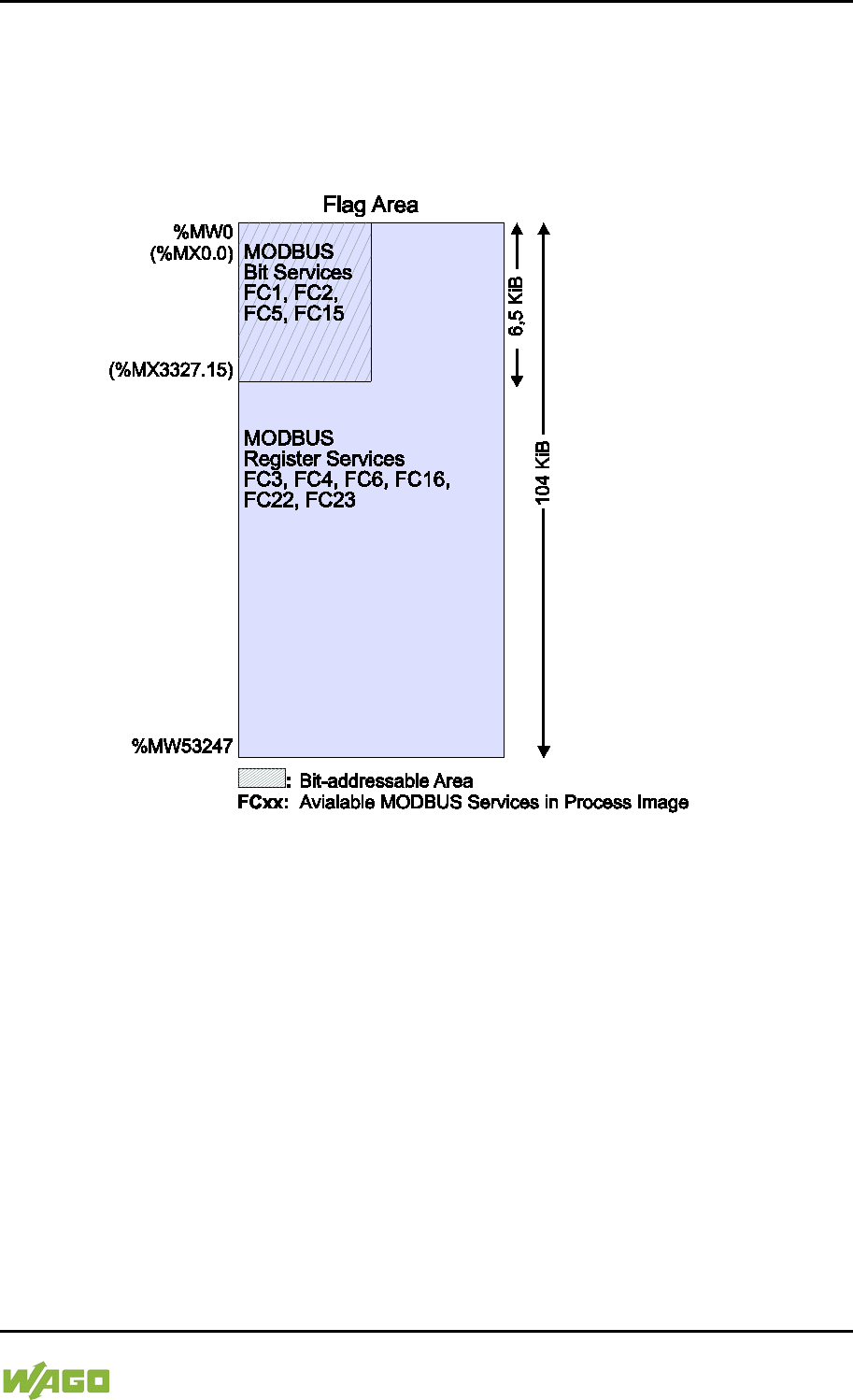
WAGO-I/O-SYSTEM 750 MODBUS – CODESYS 2 285
750-8207 PFC200 CS 2ETH RS 3G
Manual
Draft version 1.2.1 from 2017-09-13, valid from FW Version 02.06.20(09)
10.4.2 Flag Area
MODBUS can also exchange data and fieldbus variables with the PLC via the
flag area. Caution is urged, however, when using data and/or variables in this
area that is accessed by both MODBUS and the PLC. This “conflicting” access is
not protected from either side and could result in data inconsistency.
Figure 107: Flag Area
The figure shows the maximum addressable flag area with a size of 104 kB.
The actual addressable flag area depends on the current memory arrangement in
the target system settings in CODESYS.
The default setting is 24 kB.

286 MODBUS – CODESYS 2 WAGO-I/O-SYSTEM 750
750-8207 PFC200 CS 2ETH RS 3G
Manual
Draft version 1.2.1 from 2017-09-13, valid from FW Version 02.06.20(09)
10.4.3 MODBUS Registers
WAGO-specific registers are implemented in the last MODBUS-relevant address
area; this simplifies the reading of certain system and MODBUS information, as
well as configuration.
The MODBUS address area reserved for these registers ranging from the
MODBUS starting address of 4096 (0x1000) up to the MODBUS end address of
12287 (0x2FFF), without any allocation to the IEC 61131 address area. These
registers can be queried using the register read services FC3, FC4 and FC23
and with the register write services FC6, FC16 and FC23. A detailed description
of the individual registers is given in the section “WAGO MODBUS Registers”.
10.4.4 MODBUS Mapping
10.4.4.1 MODBUS Mapping for Write Bit Services FC1, FC2
The table below outlines the mapping for the MODBUS-reading, bit-oriented
services:
• FC1 – Read Single Coil,
• FC2 – Read Discrete Inputs.
Table 206: MODBUS Mapping for Read Bit Services FC1, FC2
MODBUS Address
(hexadecimal values
in parentheses)
IEC 61131
Address
Description
0 … 6143
(0x0000 … 0x17FF)
%IX1000.0 …
%IX1383.15
MODBUS Output:
6144 PFC input bit variables in the first
384 registers/words (768 bytes) of the
2kB MODBUS output process image in
the PII.
Note: In this area, the read bit services
return the content from the bit-
addressed
PII.
6144 … 12287
(0x1800 … 0x2FFF)
%QX1000.0 …
%QX1383.15
MODBUS Input:
6144 PFC output bit variables in the first
384 registers/words (768 bytes) of the 2
kB MODBUS-input process image in the
PIO.
12288 … 65535
(0x3000 … 0xFFFF)
%MX0.0 …
%MX3327.15
Maximum bit-addressable flag area:
53248 bit flags (6.5 kB);
the actual addressable flag area
depends on the current memory
arrangement in CODESYS.

WAGO-I/O-SYSTEM 750 MODBUS – CODESYS 2 287
750-8207 PFC200 CS 2ETH RS 3G
Manual
Draft version 1.2.1 from 2017-09-13, valid from FW Version 02.06.20(09)
10.4.4.2 MODBUS Mapping for Write Bit Services FC5, FC15
The table below outlines the mapping for the MODBUS-writing, bit-oriented
services:
• FC5 – Write Single Coil
• FC15 – Write Multiple Coils
Table 207: MODBUS Mapping for Write Bit Services FC5, FC15
MODBUS Address
(hexadecimal values
in parentheses)
IEC 61131
Address
Description
0 … 6143
(0x0000 … 0x17FF)
%IX1000.0 …
%IX1383.15
MODBUS Output:
6144 PFC input bit variables in the first
384 registers/words (768 bytes) of the
2kB MODBUS output process image in
the PII.
6144 … 12287
(0x1800 … 0x2FFF)
%QX1000.0 …
%QX1383.15
MODBUS Output:
MODBUS-only area for bit-oriented write
access.
Bit-based write services for this area are
acknowledged by the MODBUS slave
with the MODBUS exception code
“ILLEGAL DATA ADDRESS” (0x02).
12288 … 65535
(0x3000 … 0xFFFF)
%MX0.0 …
%MX3327.15
Maximum bit-addressable flag area:
53248 bit flags (6.5 kB);
the actual addressable flag area
depends on the current memory
arrangement in CODESYS.

288 MODBUS – CODESYS 2 WAGO-I/O-SYSTEM 750
750-8207 PFC200 CS 2ETH RS 3G
Manual
Draft version 1.2.1 from 2017-09-13, valid from FW Version 02.06.20(09)
10.4.4.3 MODBUS Mapping for Read Register Services FC3, FC4, FC23
The table below outlines the mapping for the MODBUS-reading, register-oriented
services:
• FC3 – Read Holding Registers,
• FC4 – Read Input Registers,
• FC23 – Read/Write Multiple Registers
Table 208: MODBUS Mapping for Read Register Services FC3, FC4, FC23
MODBUS Address
(hexadecimal values
in parentheses)
IEC 61131
Address
Description
0 … 999
(0x0000 … 0x03E7)
%IW1000 …
%IW1999
MODBUS Output:
1000 PFC input registers/words in the
2 kB MODBUS output process image in
the PII.
Note: In this area, the read register
services return the content from the PII.
1000 … 1999
(0x03E8 … 0x07CF)
%QW1000 …
%QW1999
MODBUS Input:
1000 PFC output registers/words in the
2 kB MODBUS input process image in
the PIO.
Note on FC23:
Only the Read portion of this service can
be executed.
2000 … 4095
(0x07D0 … 0x0FFF)
Inhibited to MODBUS-only area for
register-oriented read access. Register-
based read services for this area are
acknowledged by the MODBUS slave
with the MODBUS exception code
“ILLEGAL DATA ADDRESS” (0x02).
4096 … 12287
(0x1000 … 0x2FFF)
No IEC 61131
address
Information and configuration registers:
Not all MODBUS addresses in this range
are valid.
Valid MODBUS addresses are described
in the Section “WAGO MODBUS
Registers”.
Access to invalid addresses are
acknowledged by the MODBUS slave
with the MODBUS exception code
“ILLEGAL DATA ADDRESS” (0x02).
Note on FC23:
The Write portion of this service can only
be executed for registers that data can
be written to.

WAGO-I/O-SYSTEM 750 MODBUS – CODESYS 2 289
750-8207 PFC200 CS 2ETH RS 3G
Manual
Draft version 1.2.1 from 2017-09-13, valid from FW Version 02.06.20(09)
Table 208: MODBUS Mapping for Read Register Services FC3, FC4, FC23
MODBUS Address
(hexadecimal values
in parentheses)
IEC 61131
Address
Description
12288 … 65535
(0x3000 … 0xFFFF)
%MW0 …
%MW53247
Maximum addressable flag area:
53248 register/word flags (104 kB);
the actual addressable flag area
depends on the current memory
arrangement in CODESYS.

290 MODBUS – CODESYS 2 WAGO-I/O-SYSTEM 750
750-8207 PFC200 CS 2ETH RS 3G
Manual
Draft version 1.2.1 from 2017-09-13, valid from FW Version 02.06.20(09)
10.4.4.4 MODBUS Mapping for Write Register Services FC6, FC16, FC22, FC23
The table below outlines the mapping for MODBUS-writing, register-oriented
services.
• FC6 – Write Single Register,
• FC16 – Write Multiple Registers,
• FC22 – Mask Write Register, not for information and configuration registers
• FC23 – Read/Write Multiple Registers.
Table 209: MODBUS Mapping for Write Register Services FC6, FC16, FC22, FC23
MODBUS Address
(hexadecimal values
in parentheses)
IEC 61131
Address
Description
0 … 999
(0x0000 … 0x03E7)
%IW1000 …
%IW1999
MODBUS Output:
1000 PFC input registers/words in the
2 kB MODBUS output process image in
the PII.
1000 … 1999
(0x03E8 … 0x07CF)
No access to:
%QW1000 …
%QW1999
MODBUS Output:
Inhibited MODBUS area for register-
oriented write access.
Register-oriented write services in this
area ar
e acknowledged by the MODBUS
slave with the MODBUS exception code
“ILLEGAL DATA ADDRESS” (0x02).
2000 … 4095
(0x07D0 … 0x0FFF)
Inhibited MODBUS area for register-
oriented write access.
Register-oriented write services in this
area are acknowledged by the MODBUS
slave with the MODBUS exception code
“ILLEGAL DATA ADDRESS” (0x02).
4096 … 12287
(0x1000 … 0x2FFF)
FC6, FC16, FC23
only,
not FC22
No IEC 61131
address
Information and Configuration Registers:
Not all MODBUS addresses in this area
are valid and not all registers can be
written to.
Valid MODBUS addresses are described
in the Section “WAGO MODBUS
Registers”.
Access to invalid addresses are
acknowledged by the MODBUS slave
with the MODBUS exception code
“ILLEGAL DATA ADDRESS” (0x02).

WAGO-I/O-SYSTEM 750 MODBUS – CODESYS 2 291
750-8207 PFC200 CS 2ETH RS 3G
Manual
Draft version 1.2.1 from 2017-09-13, valid from FW Version 02.06.20(09)
Table 209: MODBUS Mapping for Write Register Services FC6, FC16, FC22, FC23
MODBUS Address
(hexadecimal values
in parentheses)
IEC 61131
Address
Description
12288 … 65535
(0x3000 … 0xFFFF)
%MW0 …
%MW53247
Maximum addressable flag area:
53248 register/word flags (104 kB);
the actual addressable flag area
depends on the current memory
arrangement in CODESYS.

292 MODBUS – CODESYS 2 WAGO-I/O-SYSTEM 750
750-8207 PFC200 CS 2ETH RS 3G
Manual
Draft version 1.2.1 from 2017-09-13, valid from FW Version 02.06.20(09)
10.5 WAGO MODBUS Registers
System and MODBUS data can be read and some MODBUS parameters
configured using the WAGO MODBUS registers. The following table lists all of
the WAGO MODBUS registers.
Table 210: WAGO MODBUS Registers
MODBUS Address
Data Length
in Words Access Description
Dec.
Hex.
4130
0x1022
1
ro
Number of registers in the
MODBUS input process image in
the PAA
4131
0x1023
1
ro
Number of registers in the
MODBUS output process image
in the PAE
4132
0x1024
1
ro
Number of bits in the MODBUS
input process image in the PAA
4133
0x1025
1
ro
Number of bits in the MODBUS
output process image in the PAE
4136
0x1028
1
ro
IP configuration: BootP(1),
DHCP(2) or permanently coded
IP address(4)
4138
0x102A
1
ro
Number of established TCP
connections
4144
0x1030
1
r/w
MODBUS TCP Timeout
(Changes apply only to new
connections)
4145
0x1031
3
ro
MAC ID of the ETHERNET
interface (eth0)
4151
0x1037
1
r/w
MODBUS TCP response delay
4160
0x1040
1
ro
PLC status
4352
0x1100
1
wo
Watchdog command
4353
0x1101
1
ro
Watchdog status
4354
0x1102
1
rw
Watchdog timeout (configuration
register)
4355
0x1103
1
rw
Watchdog config (configuration
register)
4356
0x1104
1
rw
Watchdog operation mode
(configuration register)
8192
0x2000
1
ro
0x0000 (constant)
8193
0x2001
1
ro
0xFFFF (constant)
8194
0x2002
1
ro
0x1234 (constant)
8195
0x2003
1
ro
0xAAAA (constant)
8196
0x2004
1
ro
0x5555 (constant)

WAGO-I/O-SYSTEM 750 MODBUS – CODESYS 2 293
750-8207 PFC200 CS 2ETH RS 3G
Manual
Draft version 1.2.1 from 2017-09-13, valid from FW Version 02.06.20(09)
Table 210: WAGO MODBUS Registers
MODBUS Address
Data Length
in Words Access Description
Dec.
Hex.
8197
0x2005
1
ro
0x7FFF (constant)
8198
0x2006
1
ro
0x8000 (constant)
8199
0x2007
1
ro
0x3FFF (constant)
8200
0x2008
1
ro
0x4000 (constant)
8208
0x2010
1
ro
Revision (firmware index)
8209
0x2011
1
ro
Series code
8210
0x2012
1
ro
Device code
8211
0x2013
1
ro
Major firmware version
8212
0x2014
1
ro
Minor firmware version
8213
0x2015
1
ro
MBS version
The WAGO MODBUS registers are described in more details in the following
sections.
10.5.1 Process Image Properties
10.5.1.1 Register 0x1022 – Number of Registers in the MODBUS Input
Process Image
This register contains the number of registers available in the MODBUS input
process image (MODBUS input).
10.5.1.2 Register 0x1023 – Number of Registers in the MODBUS Output
Process Image
This register contains the number of registers available in the MODBUS output
process image (MODBUS output).
10.5.1.3 Register 0x1024 – Number of Bits in the MODBUS Input Process
Image
This register contains the number of bits available in the MODBUS input process
image (MODBUS input).
10.5.1.4 Register 0x1025 – Number of Bits in the MODBUS Output Process
Image
This register contains the number of bits available in the MODBUS output
process image (MODBUS output).

294 MODBUS – CODESYS 2 WAGO-I/O-SYSTEM 750
750-8207 PFC200 CS 2ETH RS 3G
Manual
Draft version 1.2.1 from 2017-09-13, valid from FW Version 02.06.20(09)
10.5.2 Network Configuration
10.5.2.1 Register 0x1028 – IP Configuration
This register contains information about the set IP configuration.
Possible values:
1 = BootP
2 = DHCP
4 = Fixed IP address
10.5.2.2 Register 0x102A – Number of Established TCP Connections
This register supplies the number of established TCP connections.
The maximum number of MODBUS TCP connections is 1000.
10.5.2.3 Register 0x1030 – MODBUS TCP Socket Timeout
This register contains the timeout value for the TCP sockets.
This value is given in units of 100ms (ticks). A new value is accepted only for new
connections which have not yet been established. In the event of any changes,
the already established connections will continue to operate using the previously
set timeout value.
10.5.2.4 Register 0x1031 – MAC Address for ETHERNET-Interface 1 (eth0)
This register provides the MAC address for the first ETHERNET interface (eth0).
MAC may also provide a partial result.
10.5.2.5 Register 0x1037 - MODBUS TCP Response Delay
This register saves the value of the MODBUS response delay.
This value is specified in ms units. The maximum delay is 32 ms, default value is
0 ms (no delay).
Transmission of the response to a MODBUS request is delayed from the time of
processing (read and/or write register values) by the time set. In the meantime,
incoming requests can only be processed when the previous response is sent.
For MODBUS UDP, this applies to all requests and for MODBUS TCP, for each
connection. The actual length of time between a MODBUS request and the
associated response depends on the number of parallel requests overall system
utilization; it is always greater than the response delay set. Changes to the
response delay become effective immediately for each subsequent request.
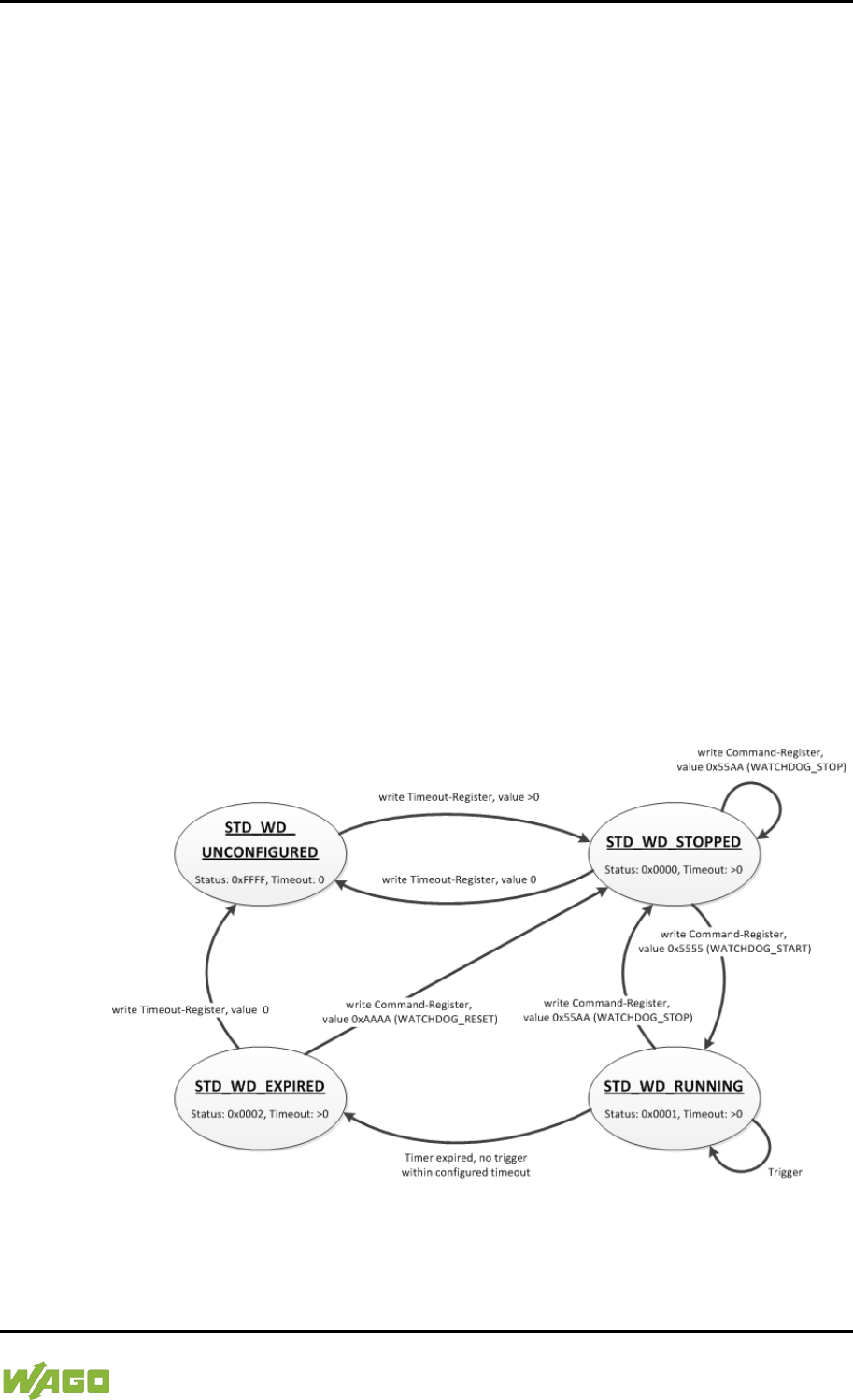
WAGO-I/O-SYSTEM 750 MODBUS – CODESYS 2 295
750-8207 PFC200 CS 2ETH RS 3G
Manual
Draft version 1.2.1 from 2017-09-13, valid from FW Version 02.06.20(09)
10.5.3 PLC Status Register
Register 0x1040 provides the status (state) that the controller is currently in.
Possible values:
1 = PLC running − PLC status is RUNNING.
2 = PLC stopped − PLC status is STOPPED.
10.5.4 MODBUS Watchdog
The MODBUS watchdog monitors in the MODBUS slave the ongoing MODBUS
communication with the MODBUS master. All valid MODBUS requests of a
MODBUS master from all the services supported by the MODBUS slave are
trigger events (see chapter “MODBUS Mapping”). This does not apply to the
Explicit Trigger mode and the access to the register 0x1101 (Watchdog Status),
which can be configured via the 0x1103 (Watchdog Config) register.
If no trigger occurs during the watchdog within the timeout time set in the 0x1102
register (Watchdog Timeout), the “Watchdog Timeout” response is initiated. The
closing of all MODBUS TCP connections can be configured as a response, see
register 0x1103 (Watchdog Config).
The MODBUS watchdog supports two different functions
STANDARD_WATCHDOG and ALTERNATIVE_WATCHDOG. The operation
mode can be selected via the register 0x1104 (Watchdog Operation Mode).
The following diagrams show the possible states of the MODBUS watchdog and
status transitions for the particular operation mode.
Figure 108: State Diagram, STANDARD_WATCHDOG Operation Mode
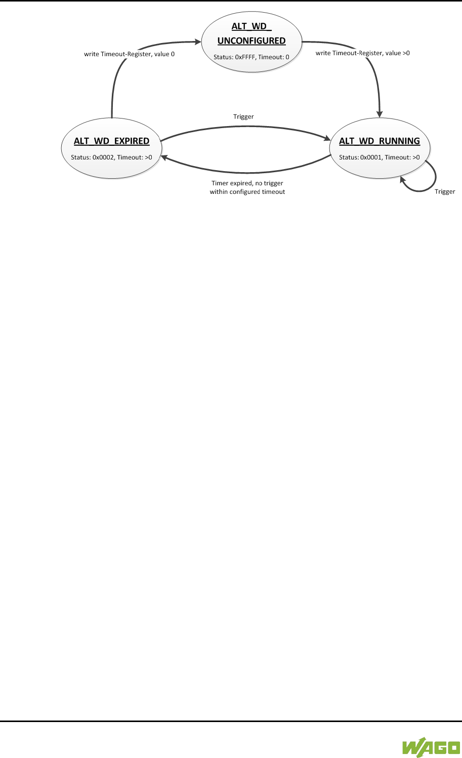
296 MODBUS – CODESYS 2 WAGO-I/O-SYSTEM 750
750-8207 PFC200 CS 2ETH RS 3G
Manual
Draft version 1.2.1 from 2017-09-13, valid from FW Version 02.06.20(09)
Figure 109: State Diagram, ALTERNATIVE_WATCHDOG Operation Mode
The state diagram for the ALTERNATIVE_WATCHDOG operation mode shows
that the watchdog is always active as soon as a timeout time > 0 is set in the
register 0x1102 (Watchdog Timeout). The writing of commands in the register
0x1100 (Watchdog Command) is limited in this operation mode. Only the
WATCHDOG_START command is permitted as a possible trigger. The only
possibilities to deactivate or stop the watchdog in ALTERNATIVE_WATCHDOG
mode are the setting of the timeout register to 0 after the timeout has elapsed
and the switching back to the STANDARD_WATCHDOG operation mode.
The following diagram shows the possible state transitions when operation
modes are switched.
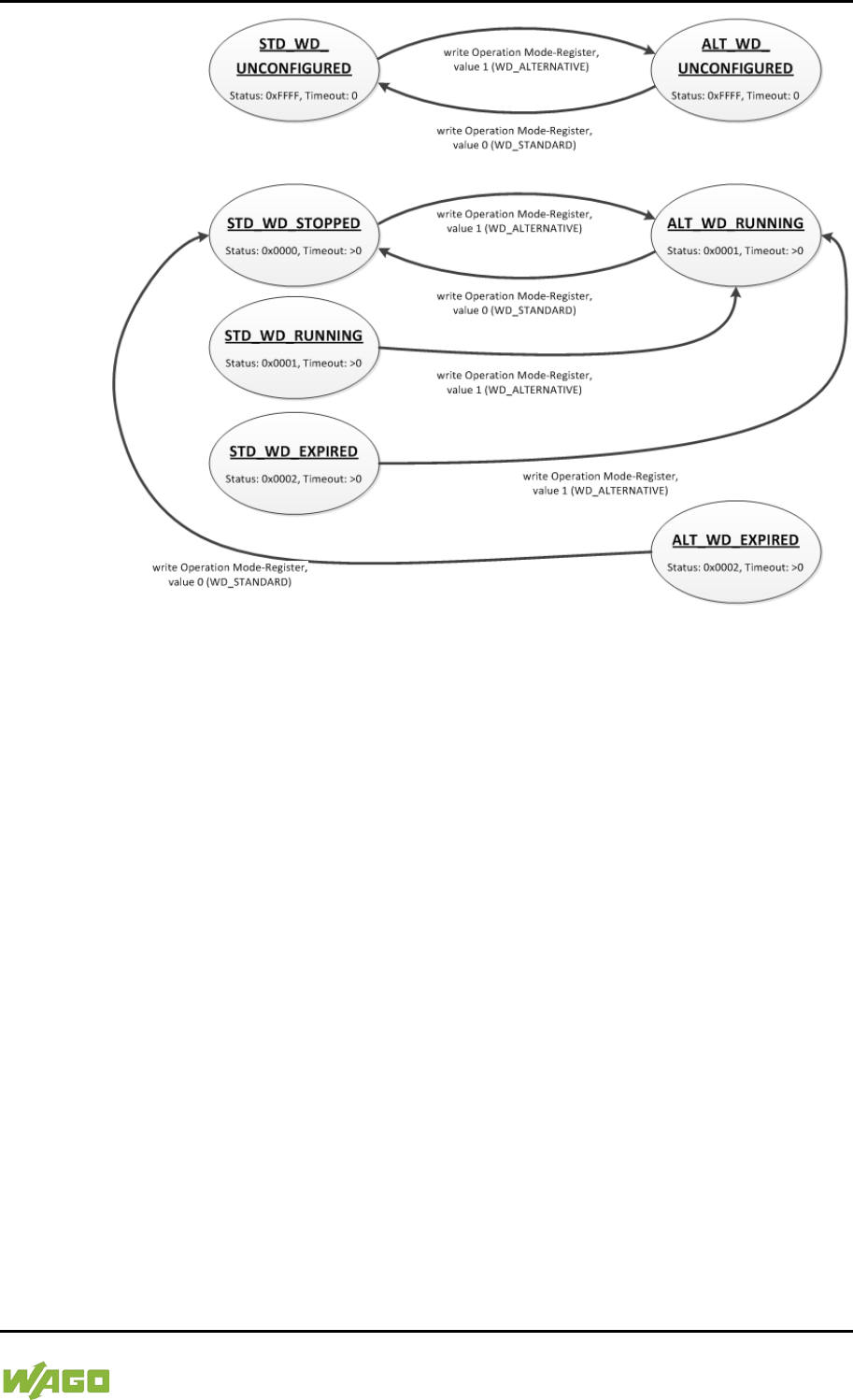
WAGO-I/O-SYSTEM 750 MODBUS – CODESYS 2 297
750-8207 PFC200 CS 2ETH RS 3G
Manual
Draft version 1.2.1 from 2017-09-13, valid from FW Version 02.06.20(09)
Figure 110: State Diagram, Switchover Operation Mode
10.5.4.1 Register 0x1100 – Watchdog Command
This register receives commands for the MODBUS watchdog. It cannot be read,
i.e. it is not possible to read out the last command written.
The following commands are accepted depending on watchdog status:

298 MODBUS – CODESYS 2 WAGO-I/O-SYSTEM 750
750-8207 PFC200 CS 2ETH RS 3G
Manual
Draft version 1.2.1 from 2017-09-13, valid from FW Version 02.06.20(09)
Table 211: Watchdog Commands
Value
Name
Explanation
0x5555
WATCHDOG_
START
Starts the configured watchdog;
in the WATCHDOG_UNCONFIGURED state if
no timeout is configured, the response is an
ILLEGAL_DATA_VALUE (0x03) exception. In
the WATCHDOG_EXPIRED state and the
STANDARD_WATCHDOG operation mode the
response is an ILLEGAL_FUNCTION (0x01)
exception. The watchdog must in this case be
reset first with the command
WATCHDOG_RESET to the
WATCHDOG_STOPPED state. In all other
cases the watchdog is restarted and the
WATCHDOG_RUNNING state is set.
0x55AA
WATCHDOG_
STOP
Stops the running watchdog;
in the WATCHDOG_UNCONFIGURED state,
the response is an ILLEGAL_DATA_
VALUE (0x03) exception if no timeout time is
set. In the WATCHDOG_EXPIRED state and
the STANDARD_WATCHDOG operation mode
the response is an ILLEGAL_FUNCTION (0x01)
exception. In this case the watchdog must first
be reset with the WATCHDOG_
RESET command to the WATCHDOG_
STOPPED state. In operation mode
ALTERNATIVE_WATCHDOG the response is
an ILLEGAL_DATA_
VALUE (0x03) exception. The command is not
generally permitted in this operation mode. In all
other cases, the watchdog is stopped
successfully and the WATCHDOG_
STOPPED state is set. In the
WATCHDOG_STOPPED state, a stop
command received several times in a row does
not have any impact on the behavior of the
watchdog and is therefore not acknowledged
with an error response.
0xAAAA
WATCHDOG_
RESET
Resets the expired watchdog;
the watchdog is reset in the
WATCHDOG_EXPIRED state and
STANDARD_WATCHDOG operation mode.
The watchdog is then in the
WATCHDOG_STOPPED state. In all other
cases the response is an ILLEGAL_
DATA_VALUE (0x03) exception.

WAGO-I/O-SYSTEM 750 MODBUS – CODESYS 2 299
750-8207 PFC200 CS 2ETH RS 3G
Manual
Draft version 1.2.1 from 2017-09-13, valid from FW Version 02.06.20(09)
10.5.4.2 Register 0x1101 – Watchdog Status
This register provides the current state of the MODBUS watchdog.
The following states are possible:
Table 212: Watchdog Status
Value
Name
Explanation
0xFFFF
WATCHDOG_
UNCONFIGURED
The MODBUS watchdog is not configured, the
“Watchdog Timeout” register (0x1102) contains
the value 0. This state can only be closed by
setting a timeout > 0.
0x0000
WATCHDOG_
STOPPED
The watchdog is configured, the “Watchdog
Timeout” register (0x1102) contains a value >0.
In the STANDARD_WATCHDOG operation
mode the watchdog can be activated in this
state by the WATCHDOG_START command.
This state cannot be reached in the
ALTERNATIVE_WATCHDOG operation mode
since the watchdog is started automatically
here.
0x0001
WATCHDOG_
RUNNING
The MODBUS watchdog is active, i.e.
configured and started. The set timeout has not
yet expired.
0x0002
WATCHDOG_
EXPIRED
The timeout set in register 0x1102 (Watchdog
Timeout) has expired. In the
STANDARD_WATCHDOG operation mode, the
watchdog in this state must be reset to the
WATCHDOG_STOPPED state with the
WATCHDOG_RESET command. In the
ALTERNATIVE_WATCHDOG operation mode,
the watchdog is automatically restarted with the
next trigger.
10.5.4.3 Register 0x1102 – Watchdog Timeout
This register contains the value for the watchdog timeout. The step width is
100 ms and the maximum value is 65535 (corresponds to 6553.5 s). The default
value is 0. In this case the watchdog cannot be started and will have the
WATCHDOG_UNCONFIGURED state.
The register can be read and written in the states
WATCHDOG_UNCONFIGURED, WATCHDOG_STOPPED and
WATCHDOG_EXPIRED. However, if the watchdog is active
(WATCHDOG_RUNNING state), this register can only be read. The response to
a write operation is an ILLEGAL_FUNCTION (0x01) exception.
10.5.4.4 Register 0x1103 – Watchdog Config
This register contains the configuration parameters for the watchdog. The
register is organized in bits, see following table.

300 MODBUS – CODESYS 2 WAGO-I/O-SYSTEM 750
750-8207 PFC200 CS 2ETH RS 3G
Manual
Draft version 1.2.1 from 2017-09-13, valid from FW Version 02.06.20(09)
The register can be read and written in the states
WATCHDOG_UNCONFIGURED, WATCHDOG_STOPPED and
WATCHDOG_EXPIRED. However, if the watchdog is active
(WATCHDOG_RUNNING state), this register can only be read. The response to
a write operation is an ILLEGAL_FUNCTION (0x01) exception.
Table 213: Watchdog Configuration
Bit
Name/Bit Identifier
Explanation
0
EXPLICIT_
TRIGGER_ONLY
Activates the Explicit Trigger mode
0*
All valid MODBUS requests are considered as
watchdog triggers. The only exception is the
access to the register 0x1101 (Watchdog Status).
1
Only the writing of register 0x1100 (Watchdog
Command) with the value 0x5555
(WATCHDOG_START) is considered as a
watchdog trigger. The access to the register
0x1101 (Watchdog Status) is also an exception
here.
1
TRIGGER_ON_
STATUS_REG
Activates the watchdog trigger by (read) access to
register 0x1101 (Watchdog Status)
0*
The reading of the watchdog status is not
considered as a watchdog trigger.
1
The reading of the watchdog status triggers the
watchdog.
2
CLOSE_ALL_TCP_
CONNECTIONS
Activates the closing of all MODBUS TCP
connections with the expiry of the timeout (transition
to WATCHDOG_EXPIRED state)
0
Existing MODBUS TCP connections remain
open.
1*
All existing MODBUS TCP connections are
closed.
* Default setting
The individual options are activated when the specific bit, or bit combination, is
set.
10.5.5 Register 0x1104 – Watchdog Operation Mode
This register contains the value for the watchdog operation mode.
The register can be both read and written irrespective of the watchdog status.
The following operation modes are possible:

WAGO-I/O-SYSTEM 750 MODBUS – CODESYS 2 301
750-8207 PFC200 CS 2ETH RS 3G
Manual
Draft version 1.2.1 from 2017-09-13, valid from FW Version 02.06.20(09)
Table 214: Watchdog Operation Modes
Value
Name
Explanation
0x0000
STANDARD_
WATCHDOG
“Standard Watchdog” operation mode;
the watchdog must be controlled explicitly via
commands (see register 0x1100 Watchdog
Command).
0x0001
ALTERNATIVE_
WATCHDOG
“Alternative Watchdog” operation mode;
the watchdog is activated immediately with a
timeout > 0 s in register 0x1102 (Watchdog
Timeout). Each trigger restarts both the running
as well as the expired watchdog. In this
operation mode the registers 0x1102
(Watchdog Timeout) and 0x1103 (Watchdog
Config) are also saved retentively with the
operation mode itself. After a device restart, the
“Alternative Watchdog” operation mode is
retained with the same configuration as before
and is therefore immediately active again when
the timeout is set.
10.5.6 MODBUS Constants Registers
Registers 0x2000 … 0x2008 provide constants based on the table “WAGO
MODBUS Registers”. It is possible to read all of the constants, or a consecutive
portion of them at once.
10.5.6.1 Electronic Nameplate
Registers 0x2010 to 0x2015 contain information from the electronic nameplate. It
is possible to read the entire nameplate or a consecutive portion of it all at once.
10.5.6.2 Register 0x2010 – Revision (Firmware Index)
This register provides the consecutive revision index (firmware index) for the
controller.
Example: 5 for Version 5.
10.5.6.3 Register 0x2011 – Series Designator
This register provides the designation (ID) for the WAGO series (Series Code) for
the controller.
Example: 750 for WAGO-I/O SYSTEM 750.
10.5.6.4 Register 0x2012 – Device ID
This register provides the device ID (WAGO Item No.) of the controller.
Example: 8206.

302 MODBUS – CODESYS 2 WAGO-I/O-SYSTEM 750
750-8207 PFC200 CS 2ETH RS 3G
Manual
Draft version 1.2.1 from 2017-09-13, valid from FW Version 02.06.20(09)
10.5.6.5 Register 0x2013 – Major Firmware Version
This register provides the major part for the firmware version.
10.5.6.6 Register 0x2014 – Minor Firmware Version
This register provides the minor part for the firmware version.
10.5.6.7 Register 0x2015 – MBS Version
This register provides the version of the MODBUS slave library. The high byte
contains the major version number and the low byte, the minor version number.
Example:
0x010A => Major version number = 1, Minor version number = 10.

WAGO-I/O-SYSTEM 750 MODBUS – CODESYS 2 303
750-8207 PFC200 CS 2ETH RS 3G
Manual
Draft version 1.2.1 from 2017-09-13, valid from FW Version 02.06.20(09)
10.6 Diagnostics
10.6.1 Diagnostics for the MODBUS Master
The status of the PLC, or of the control system, can be queried by the MODBUS
master by reading the WAGO-specific register 0x1040 – “PLC Status” using
MODBUS services FC3 (Read Holding Registers) or FC4 (Read Input Registers).
The WAGO-specific register 0x1040 – “PLC Status” is explained in the Section
“PLC Status Registers”.
The status of the MODBUS Watchdog can be requested using a register service
(FC3 or FC4) with a query to the WAGO-specific register 0x1101 – “Watchdog
Status Register”. Information about this is given in the Section “MODBUS
Watchdog”.
The MODBUS service “Get Communication Event Counter” (FC11) is not
supported in the current MODBUS slave Version V1.0.
10.6.2 Diagnostics for the Runtime System
Diagnostics for the MODBUS slaves can be executed by integrating the
CODESYS library “BusDiag.lib” via the runtime system. The required function
block, “DiagGetBusState() indicates the status of the fieldbus (here MODBUS)
and is located in this library. Details about this function block are provided both in
this document and in the online Help function for CODESYS.
10.6.3 Diagnostics for the Error Server
The MODBUS slave also supports the error service implemented in the PFC and
generates diagnostic messages, which are stored permanently (in a file), or
temporarily (in the RAM) and can be displayed directly via the WBM client. The
following diagnoses are generated by the MODBUS slave:
Table 215: Diagnostics for the Error Server
Diagnostics
ID
Diagnostic text
Method of
saving
Explanation
0x00090000
Modbus Slave
library loaded
Temporary
MODBUS slave library has
been successfully loaded.
0x00090001
Modbus Slave
library closed
Temporary
MODBUS slave library has
been successfully unloaded.
0x00090002
Modbus Slave
TCP started
Temporary
MODBUS slave successfully
started in TCP mode.
0x00090003
Modbus Slave
TCP start failed
Permanent
Starting the MODBUS slave in
the TCP mode failed.
0x00090004
Modbus Slave
TCP terminated
Temporary
MODBUS slave TCP mode
successfully terminated.
0x00090005
Modbus Slave
UDP started
Temporary
MODBUS slave successfully
started in UDP mode.

304 MODBUS – CODESYS 2 WAGO-I/O-SYSTEM 750
750-8207 PFC200 CS 2ETH RS 3G
Manual
Draft version 1.2.1 from 2017-09-13, valid from FW Version 02.06.20(09)
Table 215: Diagnostics for the Error Server
Diagnostics
ID
Diagnostic text
Method of
saving
Explanation
0x00090006
Modbus Slave
UDP start failed
Permanent
Starting the MODBUS slave in
UDP mode failed.
0x00090007
Modbus Slave
UDP terminated
Temporary
MODBUS slave UDP mode
successfully terminated.
0x00090008
Modbus Slave
RTU started
Temporary
MODBUS slave successfully
started in the RTU mode.
0x00090009
Modbus Slave
RTU start failed
Permanent
Starting the MODBUS slave in
RTU mode failed.
0x0009000A
Modbus Slave
RTU terminated
Temporary
MODBUS slave RTU mode
successfully terminated.
0x0009000B
Modbus Slave
data exchange
started by PLC
Temporary
MODBUS slave data
exchange started.
0x0009000C
Modbus Slave
data exchange
stopped by PLC
Temporary
MODBUS slave data
exchange stopped.
0x0009000F
Modbus Slave
PLC watchdog
timer expired
Permanent
Monitoring time for controller
(PLC) expired.
0x00090100
Modbus Slave
common
configuration
failed.
Permanent
MODBUS slave configuration
failed.
0x00090101
Modbus Slave
TCP configured
successfully.
Temporary
MODBUS slave TCP
configuration completed
successfully.
0x00090102
Modbus Slave
TCP configuration
failed.
Permanent
MODBUS slave TCP
configuration failed.
0x00090103
Modbus Slave
UDP configured
successfully
Temporary
MODBUS slave UDP
configuration completed
successfully.
0x00090104
Modbus Slave
UDP configuration
failed.
Permanent
MODBUS slave UDP
configuration failed.
0x00090105
Modbus Slave
RTU configured
successfully.
Temporary
MODBUS slave RTU
configuration completed
successfully.
0x00090106
Modbus Slave
RTU configuration
failed
Permanent
MODBUS slave RTU
configuration failed.
0x00090107
Port for Modbus
Slave RTU
operation not free.
Permanent
Serial port for MODBUS slave
RTU configuration already
occupied.

WAGO-I/O-SYSTEM 750 MODBUS – CODESYS 2 305
750-8207 PFC200 CS 2ETH RS 3G
Manual
Draft version 1.2.1 from 2017-09-13, valid from FW Version 02.06.20(09)
Table 215: Diagnostics for the Error Server
Diagnostics
ID
Diagnostic text
Method of
saving
Explanation
0x00090108
Modbus Slave
RTU configuration
in RS-485 mode
failed.
Permanent
MODBUS slave RTU
configuration for the RS-485
mode has failed.
0x00090200
Modbus Slave
Watchdog
activated.
Temporary
MODBUS watchdog activated.
0x00090201
Modbus Slave
Watchdog
deactivated.
Temporary
MODBUS watchdog
deactivated.
0x00090202
Modbus Slave
Watchdog Timer
expired.
Permanent
MODBUS watchdog
monitoring time expired.
0x00090203
Modbus Slave has
terminated all
established TCP
connections.
Permanent
All MODBUS TCP
connections terminated due to
timeout.
0x00090300
Modbus Slave:
obtaining system
resource failed
Permanent
Request for system resources
by the MODBUS slave has
failed.
0x00090301
Modbus Slave:
processing system
resource failed.
Permanent
Access to system resources
by the MODBUS slave has
failed.
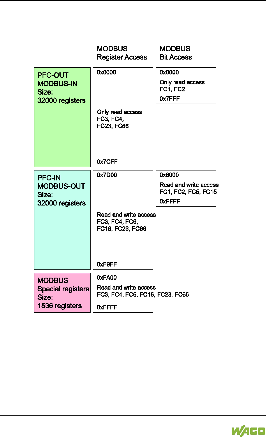
306 MODBUS – e!RUNTIME WAGO-I/O-SYSTEM 750
750-8207 PFC200 CS 2ETH RS 3G
Manual
Draft version 1.2.1 from 2017-09-13, valid from FW Version 02.06.20(09)
11 MODBUS – e!RUNTIME
11.1 MODBUS Address Overview
Figure 111: MODBUS Address Overview

WAGO-I/O-SYSTEM 750 MODBUS – e!RUNTIME 307
750-8207 PFC200 CS 2ETH RS 3G
Manual
Draft version 1.2.1 from 2017-09-13, valid from FW Version 02.06.20(09)
11.2 MODBUS Registers
Table 216: WAGO MODBUS Registers
MODBUS Address
Data Length
in Words Access Description
Dec.
Hex.
Watchdog Configuration Registers
64,000
0xFA00
1
w
Watchdog command register
64,001
0xFA01
1
rw
Watchdog timeout register
64,002
0xFA02
1
ro
Watchdog status register
64,003
0xFA03
1
rw
Watchdog config register
64,004 0xFA04 1 rw
MODBUS TCP connection
watchdog register
Status Registers
64,010 0xFA0A 1 ro
LED flash code I/O-LED
(sequence 1 of 3)
64,011 0xFA0B 1 ro
LED flash code I/O-LED
(sequence 2 of 3)
64,012 0xFA0C 1 ro
LED flash code I/O-LED
(sequence 3 of 3)
64,013
0xFA0D
1
ro
PLC State : 1 = Stop; 2 = Run
Electronic Type Label
64,016 0xFA10 4 ro
Order number, e.g.,
0750810100400001
64,020
0xFA14
1
ro
Firmware status
64,021
0xFA15
1
ro
Hardware version
64,022
0xFA16
1
ro
Firmware loader
Process Image Version
64,023 0xFA17 1 ro
Version of the MODBUS process
image
Network Configuration
64,032
0xFA20
3
ro
MAC-ID 1
Process Image Registers
64,064 0xFA40 1 ro
Number of input registers, analog
and digital (total size of the
MODBUS IN space) 0x7D00
64,065 0xFA41 1 ro
Number of input registers, analog
0x7D00
64,066 0xFA42 1 ro
Number of input registers, digital
0x8000
64,067 0xFA43 1 ro
Number of output registers,
analog and digital (total size of
the MODBUS OUT space)
0x7D00
64,068 0xFA44 1 ro
Number of output registers,
analog 0x7D00

308 MODBUS – e!RUNTIME WAGO-I/O-SYSTEM 750
750-8207 PFC200 CS 2ETH RS 3G
Manual
Draft version 1.2.1 from 2017-09-13, valid from FW Version 02.06.20(09)
Table 216: WAGO MODBUS Registers
MODBUS Address
Data Length
in Words Access Description
Dec.
Hex.
64,069 0xFA45 1 ro
Number of output registers,
digital 0x8000
Constants Registers
64,160
0xFAA0
1
ro
Constant 0x1234
64,161
0xFAA1
1
ro
Constant 0xAAAA
64,162
0xFAA2
1
ro
Constant 0x5555
64,250
0xFAFA
1
ro
Live register
The WAGO MODBUS registers are described in more details in the following
sections.
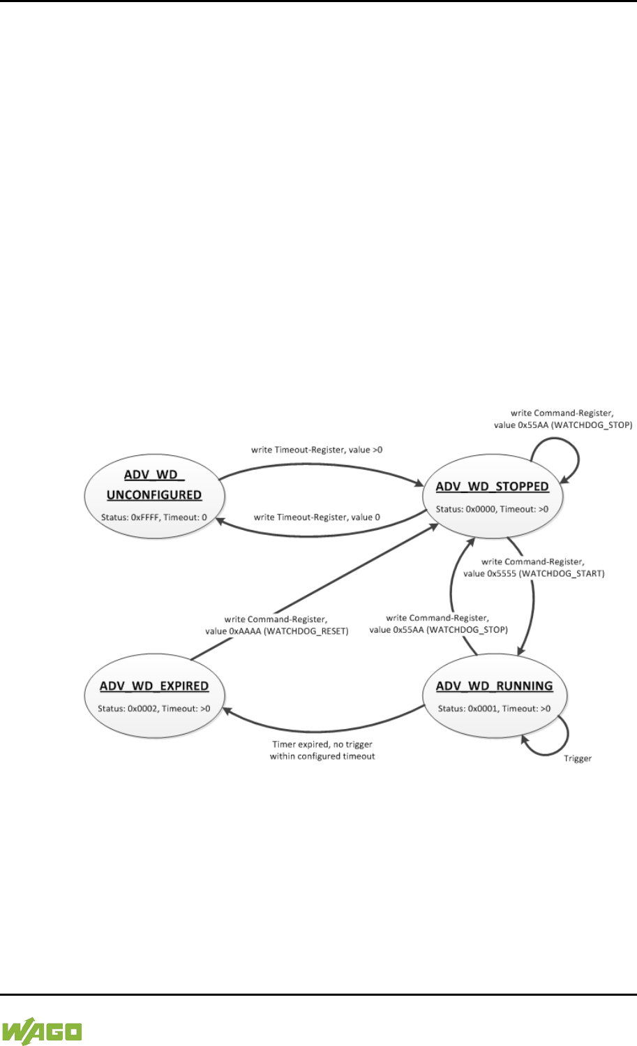
WAGO-I/O-SYSTEM 750 MODBUS – e!RUNTIME 309
750-8207 PFC200 CS 2ETH RS 3G
Manual
Draft version 1.2.1 from 2017-09-13, valid from FW Version 02.06.20(09)
11.2.1 MODBUS Watchdog
The MODBUS watchdog monitors in the MODBUS slave the ongoing MODBUS
communication with the MODBUS master. All valid MODBUS requests of a
MODBUS master from all the services supported by the MODBUS slave are
trigger events (see chapter “MODBUS Mapping”). Exceptions here are the
Explicit Trigger mode and the access to the register 0xFA02 (Watchdog Status),
which can be configured via the register 0xFA03 (Watchdog Config).
The “Watchdog Timeout” response is initiated if no trigger occurs within the
timeout set in the register 0xFA01 (Watchdog Timeout) with the watchdog
running. The closing of all MODBUS TCP connections can be configured as a
response, see register 0xFA03 (Watchdog Config).
The MODBUS watchdog supports two different operation modes
ADVANCED_WATCHDOG and SIMPLE_WATCHDOG. The operation mode can
be selected via Bit 7 in the register 0xFA03 (Watchdog Config).
The following diagrams show the possible states of the MODBUS watchdog and
status transitions for the particular operation mode.
Figure 112: State Diagram, ADVANCED_WATCHDOG Operation Mode
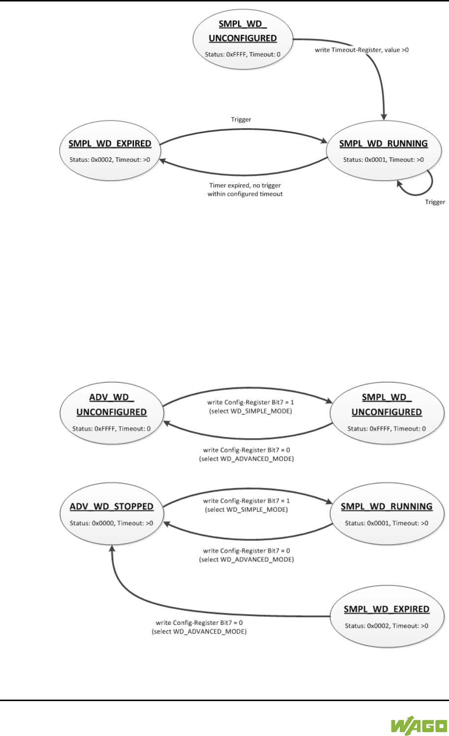
310 MODBUS – e!RUNTIME WAGO-I/O-SYSTEM 750
750-8207 PFC200 CS 2ETH RS 3G
Manual
Draft version 1.2.1 from 2017-09-13, valid from FW Version 02.06.20(09)
Figure 113: State Diagram, SIMPLE_WATCHDOG Operation Mode
The state diagram for the SIMPLE_WATCHDOG operation mode shows that the
watchdog is always active as soon as a timeout > 0 is set in the register 0xFA01
(Watchdog Timeout). The writing of commands in the register 0xFA00 (Watchdog
Command) is restricted in this operation mode. Only the WATCHDOG_START
command is permitted as a possible trigger. The only possibility to deactivate and
stop the watchdog in operation mode SIMPLE_WATCHDOG, is the switching
back to the operation mode ADVANCED_WATCHDOG.
The following diagram shows the possible state transitions when operation
modes are switched.
Figure 114: State Diagram, Switching Operation Modes

WAGO-I/O-SYSTEM 750 MODBUS – e!RUNTIME 311
750-8207 PFC200 CS 2ETH RS 3G
Manual
Draft version 1.2.1 from 2017-09-13, valid from FW Version 02.06.20(09)
11.2.1.1 Register 0xFA00 – Watchdog Command
This register receives commands for the MODBUS watchdog. It cannot be read,
i.e. it is not possible to read out the last command written.
The following commands are accepted depending on watchdog status:
Table 217: Watchdog Commands
Value
Name
Explanation
0x5555
WATCHDOG_
START
Starts the configured watchdog;
in the WATCHDOG_UNCONFIGURED state if
no timeout is configured, the response is an
ILLEGAL_DATA_VALUE (0x03) exception. The
same exception is returned even if the
watchdog has expired
(WATCHDOG_EXPIRED) in the ADVANCED_
WATCHDOG operation mode. The watchdog
must in this case be reset first with the
command WATCHDOG_RESET to the
WATCHDOG_STOPPED state. In all other
cases the watchdog is restarted and the
WATCHDOG_RUNNING state is set.
0x55AA
WATCHDOG_
STOP
Stops the running watchdog;
in the WATCHDOG_UNCONFIGURED state,
the response is an ILLEGAL_DATA_
VALUE (0x03) exception if no timeout time is
set. The same exception is returned even if the
watchdog has expired
(WATCHDOG_EXPIRED) in the ADVANCED_
WATCHDOG operation mode. The watchdog
must in this case be reset first with the
command WATCHDOG_RESET to the
WATCHDOG_STOPPED state. In the SIMPLE_
WATCHDOG operation mode the response is
an ILLEGAL_DATA_VALUE (0x03) exception.
The command is not generally permitted in this
operation mode. In all other cases, the
watchdog is stopped and the
WATCHDOG_STOPPED state is set. In the
WATCHDOG_STOPPED state a stop
command received several times in a row does
not have any impact on the behavior of the
watchdog and is therefore not acknowledged
with an error response.
0xAAAA
WATCHDOG_
RESET
Resets the expired watchdog;
in the WATCHDOG_EXPIRED state the
ADVANCED_WATCHDOG operation mode
resets the watchdog. The watchdog is then in
the WATCHDOG_STOPPED state. In all other
cases the response is an ILLEGAL_
DATA_VALUE (0x03) exception.

312 MODBUS – e!RUNTIME WAGO-I/O-SYSTEM 750
750-8207 PFC200 CS 2ETH RS 3G
Manual
Draft version 1.2.1 from 2017-09-13, valid from FW Version 02.06.20(09)
11.2.1.2 Register 0xFA01 – Watchdog Timeout
This register contains the value for the watchdog timeout. The step width is 1 ms
and the maximum value is 65535 (corresponds to 65.535 s). The default value is
0. In this case the watchdog cannot be started and will have the
WATCHDOG_UNCONFIGURED state.
The register can be read and written in the states
WATCHDOG_UNCONFIGURED and WATCHDOG_STOPPED. However, if the
watchdog is active or expired (WATCHDOG_RUNNING and
WATCHDOG_EXPIRED state), only read access to this register is possible. The
response to a write operation is an ILLEGAL_FUNCTION (0x01) exception.
11.2.1.3 Register 0xFA02 – Watchdog Status
This register provides the current state of the MODBUS watchdog.
The following states are possible:
Table 218: Watchdog Status
Value
Name
Explanation
0xFFFF
WATCHDOG_
UNCONFIGURED
The MODBUS watchdog is not configured, i.e.,
register 0xFA01 (Watchdog Timeout) contains
the value 0. Only the setting of a timeout > 0 s
can close this state.
0x0000
WATCHDOG_
STOPPED
The MODBUS watchdog is configured, the
register 0xFA01 (Watchdog Timeout) contains a
value >0. In the ADVANCED_WATCHDOG
operation mode, the watchdog can be activated
in this state with the WATCHDOG_START
command. In the SIMPLE_WATCHDOG
operation mode, this state cannot be accessed
since the watchdog is automatically started.
0x0001
WATCHDOG_
RUNNING
The MODBUS watchdog is active, i.e.
configured and started. The set timeout has not
yet expired.
0x0002
WATCHDOG_
EXPIRED
The timeout set in register 0xFA01 (Watchdog
Timeout) has expired. In the
ADVANCED_WATCHDOG operation mode, the
watchdog in this state must be reset to the
WATCHDOG_STOPPED state with the
WATCHDOG_RESET command. In the
SIMPLE_WATCHDOG operation mode, the
watchdog is automatically restarted with the
next trigger.

WAGO-I/O-SYSTEM 750 MODBUS – e!RUNTIME 313
750-8207 PFC200 CS 2ETH RS 3G
Manual
Draft version 1.2.1 from 2017-09-13, valid from FW Version 02.06.20(09)
11.2.1.4 Register 0xFA03 – Watchdog Config
This register contains the configuration parameters for the watchdog. The
register is organized in bits, see following table.
The register can be read and written irrespective of the watchdog state in the
SIMPLE_WATCHDOG operation mode.
However, in the ADVANCED_WATCHDOG operation mode, the register can only
be read and written in the WATCHDOG_UNCONFIGURED and
WATCHDOG_STOPPED states.
If the watchdog is active (WATCHDOG_RUNNING or WATCHDOG_EXPIRED
state), only a read access is permissible. The response to a write request in this
case is an ILLEGAL_FUNCTION (0x01) exception.
Table 219: Watchdog Configuration
Bit
Name/Bit Identifier
Explanation
0
EXPLICIT_
TRIGGER_ONLY
Activates the Explicit Trigger mode
0*
All valid MODBUS requests are considered as
watchdog triggers. Access to register 0xFA02
(Watchdog Status) is the only exception.
1
Only the writing of register 0xFA00 (Watchdog
Command) with the value 0x5555
(WATCHDOG_START) is considered as the
watchdog trigger. The exception is also here the
access to the register 0xFA02 (Watchdog
Status).
1
TRIGGER_ON_
STATUS_REG
Activates the watchdog trigger by (read)
access to register 0xFA02 (Watchdog Status)
0*
The reading of the watchdog status is not
considered as a watchdog trigger.
1
The reading of the watchdog status triggers the
watchdog.
2
CLOSE_ALL_TCP_
CONNECTIONS
Activates the closing of all MODBUS TCP
connections with the expiry of the timeout (transition
to WATCHDOG_EXPIRED state)
0
Existing MODBUS TCP connections remain
open.
1*
All existing MODBUS TCP connections are
closed.
7
SELECT_
ADVANCED_
SIMPLE_MODE
Determines the watchdog operation mode
0*
Advanced Mode: The watchdog must be
controlled explicitly via commands (see register
0xFA00 Watchdog Command).
1
Simple Mode: The watchdog is activated directly
with a timeout > 0 in register 0xFA01 (Watchdog
Timeout). Each trigger restarts the running as
well as the expired watchdog. The watchdog can
only be stopped by switching to Advanced mode.

314 MODBUS – e!RUNTIME WAGO-I/O-SYSTEM 750
750-8207 PFC200 CS 2ETH RS 3G
Manual
Draft version 1.2.1 from 2017-09-13, valid from FW Version 02.06.20(09)
Table 219: Watchdog Configuration
Bit
Name/Bit Identifier
Explanation
*Default setting
The individual options are activated if the relevant bit or bit combination is set.
11.2.1.5 MODBUS TCP Connection Watchdog Register
The 0xFA04 register contains the time for the MODBUS TCP connection
watchdog. Time base is 10 ms. This enables the time to be set up to 655350 ms.
If the register contains a value > 0 s when a new TCP connection from a
MODBUS master is accepted, the watchdog for this connection is started. Later
changes to the register have no effect on the monitoring of existing connections.
If the watchdog is started and no telegram is received from the connected
MODBUS master within the set time, this connection is closed from one side with
a reset.

WAGO-I/O-SYSTEM 750 MODBUS – e!RUNTIME 315
750-8207 PFC200 CS 2ETH RS 3G
Manual
Draft version 1.2.1 from 2017-09-13, valid from FW Version 02.06.20(09)
11.2.2 Status Registers
11.2.2.1 PLC Status Register
The register 0xFA0D supplies the current status of the controller.
Possible values:
1 = PLC Stop - PLC is in STOP status.
2 = PLC Run - PLC is in RUN status
11.2.3 Electronic Nameplate
Registers 0xFA10–0xFA17 contain information from the electronic nameplate. It
is possible to read the entire nameplate or a consecutive portion of it all at once.
11.2.3.1 Order Number
The registers 0xFA10–0xFA13 contain the WAGO order number of the controller.
Example: 0750-8202/0025-0001.
0xFA10 = 0750,
0xFA11 = 8202,
0xFA12 = 0025,
0xFA13 = 0001
11.2.3.2 Firmware Version
The register 0xFA14 contains the firmware version of the controller.
11.2.3.3 Hardware Version
The register 0xFA15 contains the hardware version of the controller.
11.2.3.4 Firmware Loader/Boot Loader
The register 0xFA16 contains the firmware loader/boot loader version of the
controller.
11.2.4 MODBUS Process Image Version
The register 0xFA17 contains the MODBUS process image version of the
controller.
11.2.5 MODBUS Process Image Registers
The registers 0xFA40–0xFA45 contain size information for the process image
spaces of the controller for bit and register accesses.

316 MODBUS – e!RUNTIME WAGO-I/O-SYSTEM 750
750-8207 PFC200 CS 2ETH RS 3G
Manual
Draft version 1.2.1 from 2017-09-13, valid from FW Version 02.06.20(09)
11.2.6 Constant Registers
Registers 0xFAA0 … 0xFAA2 provide constants based on the “WAGO MODBUS
Registers” table. It is possible to read all of the constants, or a consecutive
portion of them at once.
0xFAA0 = 0x1234,
0xFAA1 = 0xAAAA,
0xFAA2 = 0x5555
11.2.7 Live Register
The register 0xFAFA can only be read and contains a counter that is incremented
with each cycle of a task of the runtime environment with read and write access
to the MODBUS process data.

WAGO-I/O-SYSTEM 750 MODBUS – e!RUNTIME 317
750-8207 PFC200 CS 2ETH RS 3G
Manual
Draft version 1.2.1 from 2017-09-13, valid from FW Version 02.06.20(09)
11.3 Estimating the MODBUS Master CPU Load
Due to the real-time characteristics of the Linux® kernel used, many data points
can generate many context changes.
For a one-off update (transmitting and receiving of a function code), a CPU time
of approx. 800 µs can be assumed.
The CPU load (cpu_load) in percent can be estimated from the cycle time (t_z)
for a query with the following rule of thumb:
cpu_load = 800 µs / t_z * 100
A cycle time of 100 ms thus results in a CPU load of 0.8%.
A maximum load of approx. 20% can be generated per connection, as this is
limited by the network protocol. To minimize the CPU load:
- The cycle time must be as high as possible.
- As many data points as possible must be combined in a query.
- The minimum query interval can be increased (default value: 0 ms).
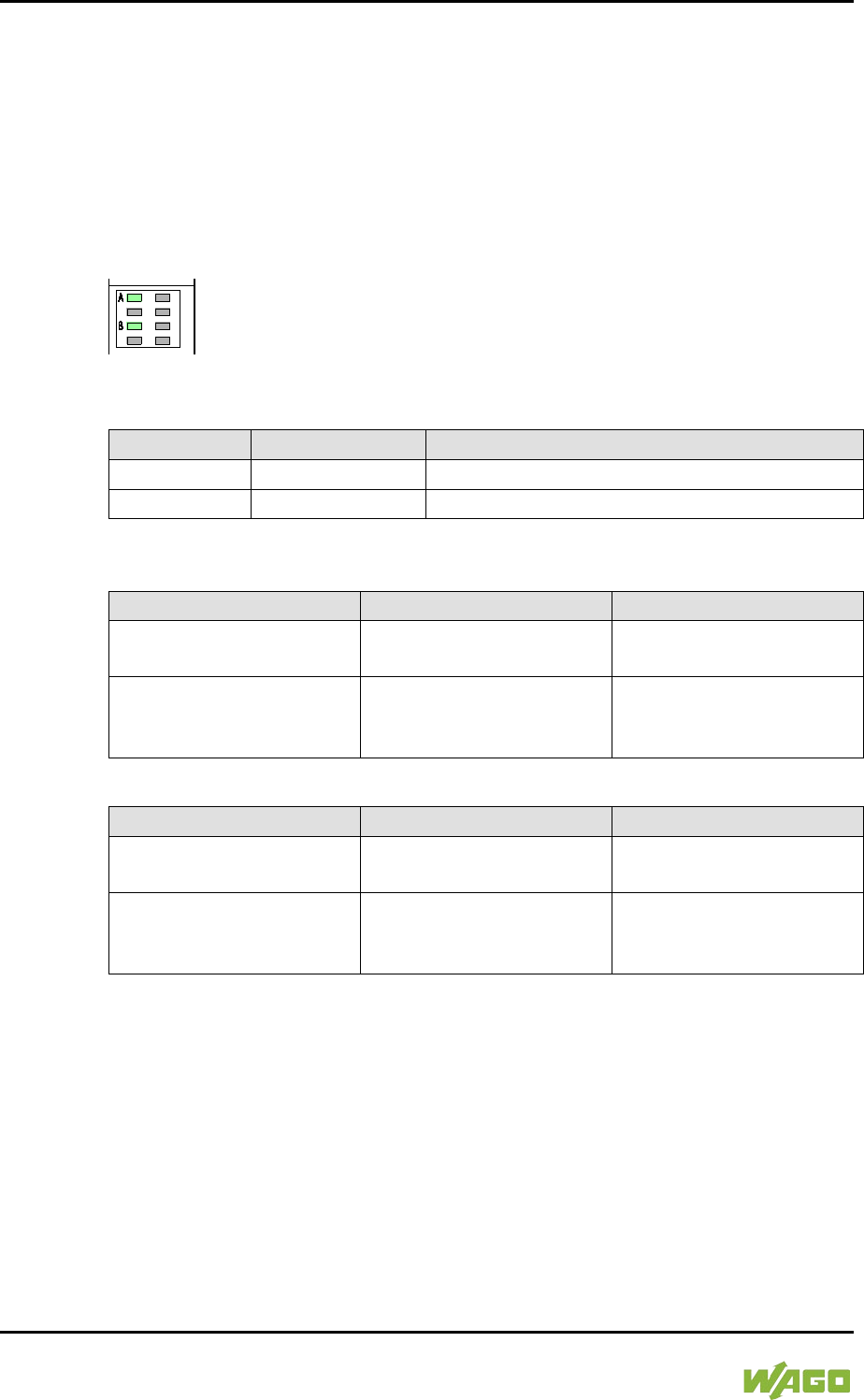
318 Diagnostics WAGO-I/O-SYSTEM 750
750-8207 PFC200 CS 2ETH RS 3G
Manual
Draft version 1.2.1 from 2017-09-13, valid from FW Version 02.06.20(09)
12 Diagnostics
12.1 Operating and Status Messages
The following tables contain descriptions of all operating and status messages for
the controller which are indicated by LEDs.
12.1.1 Power Supply Indicating Elements
Figure 115: Power Supply Indicating Elements
Table 220: Legend for Figure “Power Supply Indicating Elements”
Description
Color
Description
A
Green/off
Status of system power supply voltage
B
Green/off
Status of field-side power supply voltage
Table 221: Field-Side Supply Diagnostics
Status
Explanation
Solution
Green
24V field-side supply
voltage present
---
Off
No 24V field-side supply
voltage present
Switch on the power
supply. Check the supply
voltage.
Table 222: System Power Supply Diagnistics
Status
Explanation
Solution
Green
24V system power supply
voltage present
---
Off
No 24V system power
supply voltage present
Switch on the power
supply. Check the supply
voltage.

WAGO-I/O-SYSTEM 750 Diagnostics 319
750-8207 PFC200 CS 2ETH RS 3G
Manual
Draft version 1.2.1 from 2017-09-13, valid from FW Version 02.06.20(09)
12.1.2 Mobile Radio Network Status Indicators
Figure 116: Mobile Radio Network Status Indicators
Table 223: Legend for the “Mobile Radio Network Status Indicators” Figure
Description
Color
Description
CON
Green/off
Mobile radio network status
Table 224: Diagnostics via CON LED
Status
Explanation
Remedy
Green flashing
1800 ms ON,
200 ms OFF
2G or 3G network
---
Green flashing
200 ms ON,
1800 ms OFF
No network
- Check the SIM status via WBM.
- Enter the PIN or PUK if necessary.
- If the SIM status is “ready” and the
error persists, check the antenna
and its connection to the device.
- If necessary, connect the antenna
correctly or use another compatible
antenna.
- If possible, use a mobile phone or
comparable device to check the
signal quality of the mobile radio
network locally.
OFF
Modem firmware
update
Wait until the update process has
complete.
Do not switch off the device!

320 Diagnostics WAGO-I/O-SYSTEM 750
750-8207 PFC200 CS 2ETH RS 3G
Manual
Draft version 1.2.1 from 2017-09-13, valid from FW Version 02.06.20(09)
12.1.3 Fieldbus/System Indicating Elements
Figure 117: Indicating elements for fieldbus/system
Table 225: Diagnostics via SYS LED
Status
Explanation
Remedy
Green
Ready to operate -
System start
completed without
errors
---
Yellow
Device is in
startup/boot process
and the RST button is
not pressed.
---
Yellow flashing
“Fix IP Address”
mode,
temporary setting
until the next reboot
Connect to the device via the standard
address (192.168.1.17) or restart the
device to restore the original value set.
Green/red
flashing
Firmware update
mode
---

WAGO-I/O-SYSTEM 750 Diagnostics 321
750-8207 PFC200 CS 2ETH RS 3G
Manual
Draft version 1.2.1 from 2017-09-13, valid from FW Version 02.06.20(09)
The RUN LED indication depends on the runtime system enabled (CODESYS 2
or e!RUNTIME).
The following indications apply to the CODESYS 2 runtime system:
Table 226: Diagnostics RUN LED
Status
Explanation
Solution
Green
PLC program has the
status “Run”.
---
Green flashing
PLC program at a debug
point.
Resume the program in
the linked IDE (Integrated
Development
Environment) using
“Single step” or “Start”. If
the connection has been
interrupted, set the
Run/Stop switch to “Stop”
and then back to “Run” to
enable the program to
continue.
Green/red flashing
PLC is at a debug point
and the Run/Stop switch
has been set to “Stop”.
Set the Run/Stop switch
to “Run” to enable the
program to continue.
Red
No PLC-program loaded
or PLC program has the
status “Stop”.
Load the PLC program.
Set the Run/Stop switch
to “Run” to start the
current program.

322 Diagnostics WAGO-I/O-SYSTEM 750
750-8207 PFC200 CS 2ETH RS 3G
Manual
Draft version 1.2.1 from 2017-09-13, valid from FW Version 02.06.20(09)
The following indications apply to the e!RUNTIME runtime system:
Table 227: RUN LED Diagnostics – e!RUNTIME
Status
Explanation
Remedy
Green
Applications loaded
and all in the “RUN”
status
---
Green flashing
No application and
now boot project
loaded
Load an application or boot project.
Red
Applications loaded
and all in the “STOP”
status
Set the mode selector switch to “RUN” to
start the application.
Green/red
flashing
At least one
application in the
“RUN” status and one
in the ”STOP” status
Start the stopped application.
Red,
goes out briefly
Warm start reset
completed
---
Red,
goes out longer
Cold start reset
completed
---
Red, flashing
At least one
application after in the
“STOP” status after
exception (e.g.,
memory access error)
Start the application with a reset via the
mode selector switch or in the connected
IDE.
If the application cannot be started,
restart the controller.
Contact WAGO Support if the error
occurs again.
Orange/green
flashing
Load above threshold
value 1
Try to reduce the load on the system:
- Change the CODESYS program.
-
End any fieldbus communication that
is not essential, or reconfigure the
fieldbuses.
- Remove any non-critical tasks from
the RT area.
- Select a longer cycle time for IEC
tasks.
Orange
Runtime system in
debug state
(breakpoint, single
step, individual cycle)
Resume the application in the connected
IDE with single step or start.
Remove the breakpoint if necessary.
If the connection has been interrupted,
set the mode selector switch to “STOP”
and then back to “RUN” to enable the
application to continue
OFF
No runtime system
loaded
Enable a runtime system, e.g., via the
WBM.

WAGO-I/O-SYSTEM 750 Diagnostics 323
750-8207 PFC200 CS 2ETH RS 3G
Manual
Draft version 1.2.1 from 2017-09-13, valid from FW Version 02.06.20(09)
Table 228: Diagnostics I/O LED
Status
Explanation
Solution
Green
Data cycle on the internal
data bus, normal
operating status.
---
Orange flashing
Startup phase; the
internal data bus is being
initialized. The startup
phase is indicated by
rapid flashing for about 1
... 2 seconds.
Wait until initialization has
been completed.
Red
A hardware fault is
present.
Contact WAGO Support.
Red flashing
(2 Hz)
An error which may be
able to be eliminated is
present.
First, try to eliminate the
error by switching the
device (power supply) off
and then back on.
Check the entire node
structure for any errors.
If you cannot eliminate the
error, contact WAGO
Support.
Red flashing
(flashing sequence)
An internal data bus error
is present.
An explanation of the
flashing sequence is
given in the section
“Diagnostics Messages
via Flashing Sequences”.
Off
A library was not loaded,
or a library function was
not called up.
Restart the device.
If you cannot eliminate the
error, contact WAGO
Support.

324 Diagnostics WAGO-I/O-SYSTEM 750
750-8207 PFC200 CS 2ETH RS 3G
Manual
Draft version 1.2.1 from 2017-09-13, valid from FW Version 02.06.20(09)
Table 229: MS-LED Diagnostics
Status
Explanation
Remedy
Off
No error
---
Red flashing
(flashing
sequence)
A configuration error
exists.
An explanation of the flashing sequence
is given in the section “Diagnostics via
Flashing Sequences.”

WAGO-I/O-SYSTEM 750 Diagnostics 325
750-8207 PFC200 CS 2ETH RS 3G
Manual
Draft version 1.2.1 from 2017-09-13, valid from FW Version 02.06.20(09)
Table 230: Diagnostics via NET LED
Status
Explanation
Remedy
Green
3G network
---
Orange
2G network
---
Red
No network
- Check the SIM status via WBM.
- Enter the PIN or PUK if necessary.
- If the SIM status is “ready” and the
error persists, check the antenna
and its connection to the device.
- If necessary, connect the antenna
correctly or use another compatible
antenna.
- If possible, use a mobile phone or
comparable device to check the
signal quality of the mobile network
locally.
Red flashing,
blink code 1-1
No SIM card inserted
- Switch off the device.
- Insert a SIM card.
- Switch the device on again.
Red flashing,
blink code 1-2
Invalid/locked SIM
card
- Switch off the device.
- Insert a different SIM card that is
valid.
- Switch the device on again.
Red flashing,
blink code 2-1
Modem not
connected
A hardware fault is present. Contact
WAGO Support.
Red flashing,
blink code 2-2
Modem initialization
error (incompatible
firmware version)
Load the modem firmware originally
included as delivered from the factory
back onto the device.
Red flashing,
blink code 2-3
Timeout for modem
reset
Switch the device off and on again.

326 Diagnostics WAGO-I/O-SYSTEM 750
750-8207 PFC200 CS 2ETH RS 3G
Manual
Draft version 1.2.1 from 2017-09-13, valid from FW Version 02.06.20(09)
Table 231: Diagnostics via Signal Quality LEDs
Status of signal quality LEDs
Signal quality
▐
(S1)
█
(S2)
▐█
(S3)
██
(S4)
▐██
(S5)
OFF
OFF
OFF
OFF
OFF
No network
Yellow
OFF
OFF
OFF
OFF
Level 1
Green
OFF
OFF
OFF
OFF
Level 2
Green
Green
OFF
OFF
OFF
Level 3
Green
Green
Green
OFF
OFF
Level 4
Green
Green
Green
Green
OFF
Level 5
Green
Green
Green
Green
Green
Level 6
Table 232: Signal Quality Meaning
Signal quality
Explanation
UMTS
GSM
Level 1
Only UMTS, probable
connection failure
Only GSM, probable
connection failure
Level 2
HDSPA possible, instable
connection
GPRS, very slow data
connection
Level 3
HDSPA possible, no weather
reserve
GPRS, stabile data connection,
maximum data rate (54 kbit/s)
Level 4 HDSPA, stabile connection
EDGE, stabile, very slow data
connection possible
Level 5
HDSPA, maximum data rate
7.2 Mbit/s
EDGE, maximum data rate
(220 kBit/s)
Level 6 HSPA+ possible (if available)
E-EDGE possible (up to
1 Mbit/s)
Depending on the mobile network load and limitations set by the mobile network
service provider, the actual data rate may be slower than the signal quality allows
at the time.

WAGO-I/O-SYSTEM 750 Diagnostics 327
750-8207 PFC200 CS 2ETH RS 3G
Manual
Draft version 1.2.1 from 2017-09-13, valid from FW Version 02.06.20(09)
12.2 Diagnostics Messages via Flashing Sequences
12.2.1 Flashing Sequences
A diagnosis (fault/error) is always displayed as three flashing sequences in a
cyclic manner:
1. The first flashing sequence (flickering) initiates reporting of the fault/error.
2. After a short break (approx. 1 second), the second flashing sequence
starts. The number of blink pulses indicates the error code, which
describes the type of error involved.
3. After a further break the third flashing sequence is initiated. The number of
blink pulses indicates the error argument, which provides an additional
description of the error, e.g., which of the I/O modules connected to the
controller exhibits an error.
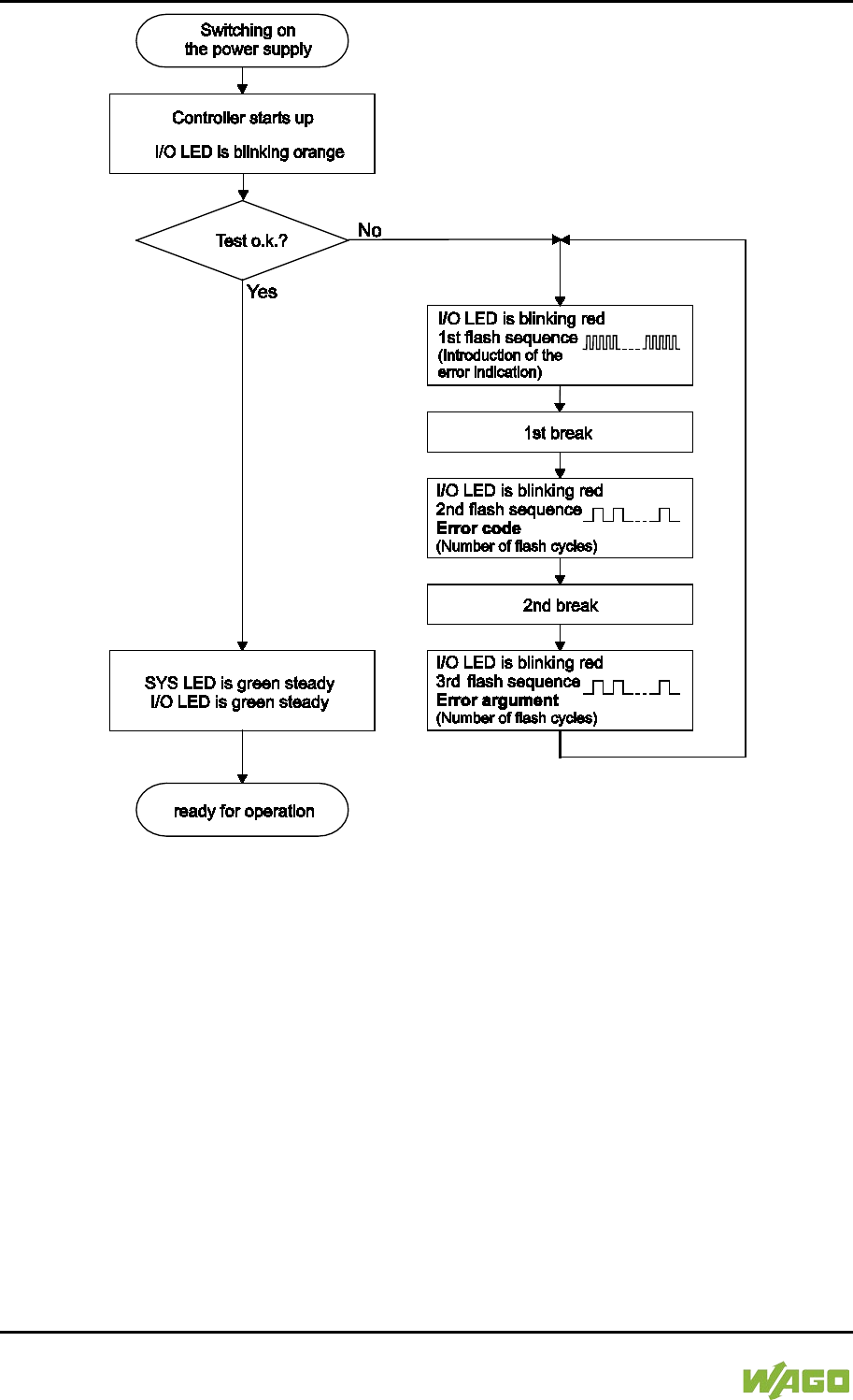
328 Diagnostics WAGO-I/O-SYSTEM 750
750-8207 PFC200 CS 2ETH RS 3G
Manual
Draft version 1.2.1 from 2017-09-13, valid from FW Version 02.06.20(09)
Figure 118: Flashing Sequence Process Diagram

WAGO-I/O-SYSTEM 750 Diagnostics 329
750-8207 PFC200 CS 2ETH RS 3G
Manual
Draft version 1.2.1 from 2017-09-13, valid from FW Version 02.06.20(09)
12.2.2 Example of a Diagnostics Message Indicated by a Flashing
Sequence
The example below illustrates the representation of a diagnostics message via a
flashing sequence. The I/O LED indicates a data error on the internal data bus.
The data error is caused by the removal of an I/O module located at the 6th
position of the bus node.
Initiation of the Start Phase
1. The I/O LED flashes for 1 cycle at about 10 Hz (10 flashes/second).
2. This is followed by a pause of about one second.
Error Code 4: Data Error in the Internal Data Bus
3. The I/O LED flashes for 4 cycles of about 1Hz.
4. This is followed by a pause of about 1 second.
Error Argument 5: I/O Module at the 6th Slot
5. The I/O LED flashes for 5 cycles at 1 Hz.
This indicates that a disruption has occurred at the internal data bus
downcircuit of the 5th I/O module.
6. The blink code starts flickering when the start phase is initiated again. If
there is only one error, this process is repeated.

330 Diagnostics WAGO-I/O-SYSTEM 750
750-8207 PFC200 CS 2ETH RS 3G
Manual
Draft version 1.2.1 from 2017-09-13, valid from FW Version 02.06.20(09)
12.2.3 Meaning of Blink Codes and Procedures for
Troubleshooting
This section describes the diagnostics presented as blink codes via the I/O LEDs.
If the diagnostics cannot be cleared by the measured specified for them, contact
WAGO support. Be ready to explain to them the blink code that is displayed.
Phone: +49 571 887 555
Fax: +49 571 887 8555
E-mail: support@wago.com
Table 233: Overview of Error Codes, I/O LED
Error code
Explanation
1
Hardware and configuration error
2
Configuration error
3
Internal data bus protocol error
4
Physical error on the internal data bus
5
Internal data bus initialization error
6
Not used
7
Not used
8
Not used
9
CPU exception error

WAGO-I/O-SYSTEM 750 Diagnostics 331
750-8207 PFC200 CS 2ETH RS 3G
Manual
Draft version 1.2.1 from 2017-09-13, valid from FW Version 02.06.20(09)
Table 234: Error Code 1, Explanation of Blink Codes and Procedures for Troubleshooting
Error
Argument
Cause Remedy
-
Invalid parameter
checksum for internal
data bus interface
- Switch off the power to the controller
and replace it.
- Then switch the power back on.
1
Internal buffer
overflow (max.
amount of data
exceeded) during
inline code
generation.
- Switch off the power to the
controller.
- Reduce the number of I/O modules.
- Switch the power back on.
2
Data type of the I/O
module(s) is not
supported
- Update the controller firmware. If this
error persists, there is an error in the
I/O module. Identify the error as
follows:
- Switch off the power supply.
- Place the end module in the middle
of the I/O modules connected to the
system.
- Switch the power back on.
- If the I/O flashes red switch off the
power supply again and place the
end module in the middle of the first
half of the I/O modules (toward the
controller).
- If the LED is no longer flashing,
switch off the power supply and
place the end module in the middle
of the second half of the I/O modules
(away from the controller).
- Switch the power back on.
- Repeat this procedure until you
establish which I/O module is
defective. Then replace that module.
3
Unknown module
type of the flash
program memory
- Switch off the power to the controller
and replace it.
- Then switch the power back on.
4
Error occurred while
writing to the flash
memory
- Switch off the power to the controller
and replace it.
- Then switch the power back on.
5
Error occurred while
erasing a flash sector
6
The I/O module
configuration after an
internal data bus
reset differs from the
one after the last
controller startup.
- Restart the controller by first
switching off the power supply and
then switching it back on, or
by pressing the Reset button on the
controller.

332 Diagnostics WAGO-I/O-SYSTEM 750
750-8207 PFC200 CS 2ETH RS 3G
Manual
Draft version 1.2.1 from 2017-09-13, valid from FW Version 02.06.20(09)
Table 234: Error Code 1, Explanation of Blink Codes and Procedures for Troubleshooting
Error
Argument
Cause Remedy
7
Error occurred while
writing to the serial
EEPROM
- Switch off the power to the controller
and replace it.
- Then switch the power back on.
8
Invalid hardware/
firmware combination
9
Invalid checksum in
the serial EEPROM
10
Fault when initializing
the serial EEPROM.
11
Error occurred while
reading from the
serial EEPROM
- Switch off the power supply to the
controller and reduce the number of
I/O modules.
- Then switch the power back on.
12
Time to access the
serial EEPROM
exceeded
- Switch off the power to the controller
and replace it.
- Then switch the power back on.
14
Maximum number of
gateway or mailbox
modules exceeded.
- Switch off the power to the
controller.
- Reduce the number of gateway or
mailbox modules.
- Then switch the power back on.
16
Maximum number of
I/O modules
exceeded
- Switch off the power to the
controller.
- Reduce the number of I/O modules.
- Then switch the power back on.
Table 235: Error Code 2, Explanation of Blink Codes and Procedures for Troubleshooting
Error
Argument
Cause Remedy
2
Maximum size of the
process image
exceeded
- Switch off the power to the
controller.
- Reduce the number of I/O modules.
- Switch the power back on.

WAGO-I/O-SYSTEM 750 Diagnostics 333
750-8207 PFC200 CS 2ETH RS 3G
Manual
Draft version 1.2.1 from 2017-09-13, valid from FW Version 02.06.20(09)
Table 236: Error Code 3, Explanation of Blink Codes and Procedures for Troubleshooting
Error
Argument
Cause Solution
--
Internal data bus
communication error;
defective I/O module
cannot be identified
If a power supply module (e.g., 750-602)
is connected to the controller, ensure
that this module functions properly (see
Section “LED Signaling”). If the supply
module does not exhibit any erro
rs/faults,
the I/O module is defective. Identify the
defective I/O module as follows:
- Switch off the power supply.
- Place the end module in the middle
of the I/O modules connected to the
system.
- Switch the power back on.
- If the I/O LED continues to flash red
switch off the power supply again
and place the end module in the
middle of the first half of the I/O
modules (toward the controller).
If only one I/O module is left and the LED
continues to flash, either this module or
the controller internal data bus interface
is defective. Replace the defective
module or the controller.
- If the LED is no longer flashing,
switch off the power supply and
place the end module in the middle
of the second half of the I/O modules
(away from the controller).
- Switch the power back on.
- Repeat this procedure until you
establish which I/O module is
defective. Then replace that module.

334 Diagnostics WAGO-I/O-SYSTEM 750
750-8207 PFC200 CS 2ETH RS 3G
Manual
Draft version 1.2.1 from 2017-09-13, valid from FW Version 02.06.20(09)
Table 237: Error Code 4, Explanation of Blink Codes and Procedures for Troubleshooting
Error
Argument
Cause Solution
--
Maximum permissible
number of I/O modules
exceeded.
- Switch off the power to the controller.
- Reduce the number of I/O modules
to an acceptable value.
- Switch the power back on.
n*
Internal data bus
disruption after the nth
process data module.
- Switch off the power to the controller.
- Replace the (n+1)th process data
module.
- Switch the power back on.
I/O modules that do not provide any data
are ignored (e.g., supply module without
diagnostics).
Table 238: Error Code 5, Explanation of Blink Codes and Procedures for Troubleshooting
Error
Argument
Cause Solution
n*
Register communication
error during internal data
bus initialization
- Switch off the power to the controller.
- Replace the (n+1)th process data
module.
- Switch the power back on.
I/O modules that do not provide any data
are ignored (e.g., supply module without
diagnostics).
Table 239: Error Code 9, Explanation of Blink Codes and Procedures for Troubleshooting
Error
Argument
Cause Solution
1 Invalid program statement
Malfunction of the program sequence.
- Please contact WAGO Support.
2 Stack overflow
Malfunction of the program sequence.
- Please contact WAGO Support.
3 Stack underflow
Malfunction of the program sequence.
- Please contact WAGO Support.
4 Invalid event (NMI)
Malfunction of the program sequence.
- Please contact WAGO Support.

WAGO-I/O-SYSTEM 750 Diagnostics 335
750-8207 PFC200 CS 2ETH RS 3G
Manual
Draft version 1.2.1 from 2017-09-13, valid from FW Version 02.06.20(09)
12.2.4 Meaning of Blink Codes and Procedures for
Troubleshooting
This section describes the diagnostics presented as blink codes via the MS
LEDs.
If the diagnostics cannot be cleared by the measured specified for them, contact
WAGO support. Be ready to explain to them the blink code that is displayed.
Phone: +49 571 887 555
Fax: +49 571 887 8555
E-mail: support@wago.com
Table 240: Overview of MS-LED Error Codes
Error Code
Explanation
1
Configuration error
Table 241: Error Code 1, Explanation of Blink Codes and Procedures for Troubleshooting
Error
Argument
Cause Remedy
5
Error when
synchronizing the
controller
configuration with the
internal data bus
- Check the information of the
connected I/O modules in the
CODESYS controller configuration.
- Adjust this to match the I/O module
that is actually inserted.
- Recompile the project.
- Reload the project into the controller.
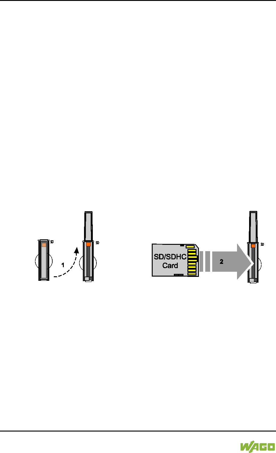
336 Service WAGO-I/O-SYSTEM 750
750-8207 PFC200 CS 2ETH RS 3G
Manual
Draft version 1.2.1 from 2017-09-13, valid from FW Version 02.06.20(09)
13 Service
13.1 Inserting and Removing the Memory Card
</dg_
13.1.1 Inserting the Memory Card
1. Use an actuating tool or a screwdriver to open the transparent cover flap by
flipping it upwards. The point where to position the tool is marked with an
arrow.
2. Hold the memory card so that the contacts are visible on the right and the
diagonal edge is at the top, as depicted in the figure below.
3. Insert the memory card in this position into the slot provided for it.
4. Push the memory card all the way in. When you let go, the memory card
will move back a little and then snap in place (push-push mechanism).
5. Close the cover flap by flipping it down and pushing it in until it snaps into
place.
6. You can seal the closed flap through the hole in the enclosure next to the
flap.
Figure 119: Inserting the Memory Card
</dg_
13.1.2 Removing the Memory Card
1. First, remove any seal that may be in place.
2. Use an actuating tool or a screwdriver to open the transparent cover flap by
flipping it upwards. The point where to position the tool is marked with an
arrow.
3. To remove the memory card you must first push it slightly into the slot
(push-push mechanism). This releases the mechanical locking mechanism.
4. As soon as you let go of the memory card, the memory card is pushed out
a bit and you can remove it.
5. Remove the memory card.

WAGO-I/O-SYSTEM 750 Service 337
750-8207 PFC200 CS 2ETH RS 3G
Manual
Draft version 1.2.1 from 2017-09-13, valid from FW Version 02.06.20(09)
6. Close the cover flap by flipping it down and pushing it in until it snaps into
place.
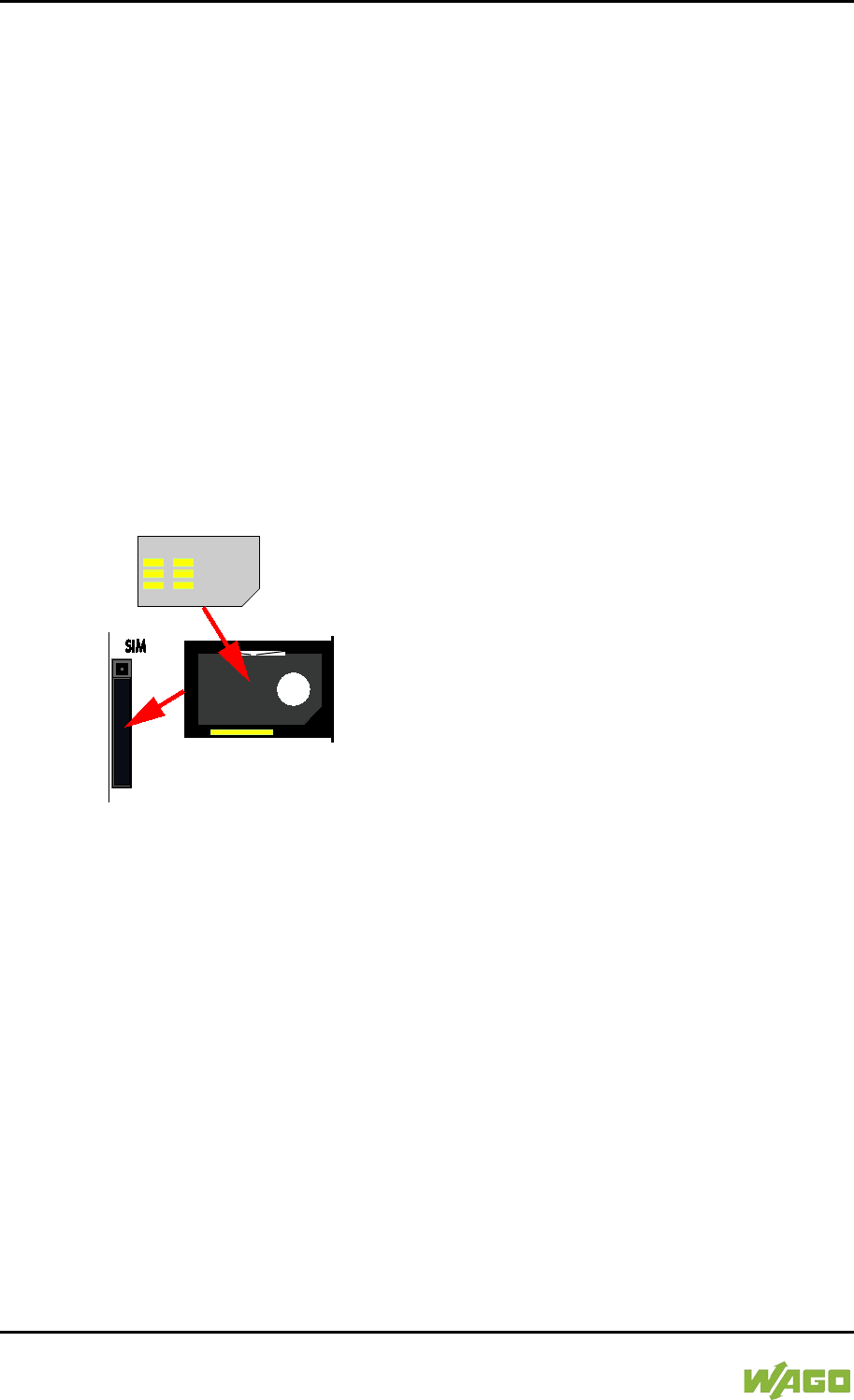
338 Service WAGO-I/O-SYSTEM 750
750-8207 PFC200 CS 2ETH RS 3G
Manual
Draft version 1.2.1 from 2017-09-13, valid from FW Version 02.06.20(09)
13.2 Inserting and Removing the SIM Card
13.2.1 Inserting the SIM Card
1. Press the release button of the SIM card slot with an appropriate object
(e.g., pen or operating tool 210-719 or 720) until the SIM card holder pops
out of the SIM card slot.
2. Remove the SIM card holder.
3. Hold the SIM card holder with the recess for the SIM card facing you.
4. Insert the SIM card into the SIM card holder in such a way that the shape of
the recess lines up with the shape of the SIM card and the contacts of the
SIM card are visible.
5. Reinsert the SIM card holder into the SIM card slot with the SIM card
(contacts visible) oriented towards the memory card slot until the SIM card
holder latches.
Figure 120: Inserting the SIM Card
13.2.2 Removing the SIM Card
1. Press the release button of the SIM card slot with an appropriate object
(e.g., pen or operating tool 210-719 or 720) until the SIM card holder pops
out of the SIM card slot.
2. Remove the SIM card holder.
3. Remove the SIM card.
4. Reinsert the SIM card holder into the SIM card slot with the recess for the
SIM card oriented towards the memory card slot until the SIM card holder
latches.
WAGO-I/O-SYSTEM 750 Service 339
750-8207 PFC200 CS 2ETH RS 3G
Manual
Draft version 1.2.1 from 2017-09-13, valid from FW Version 02.06.20(09)
13.3 Firmware Changes
Obtain documentation appropriate for the firmware target version!
A firmware upgrade or downgrade can modify, remove or add controller
properties and functions. As a result, described properties or functions of the
controller may not be available or available properties or functions may not be
described in the documentation. Therefore, use only documentation appropriate
for the target firmware after an upgrade/downgrade.
If you have any questions, feel free to contact our WAGO Support.
13.3.1 Perform Firmware Upgrade
Do not switch the controller off!
The controller can be damaged by interrupting the upgrade process.
Do not switch the controller off during the upgrade process and do not disconnect
the power supply!
Proceed as follows if you want to upgrade the controller to a later firmware
version:
1. Save your application and the controller settings.
2. Switch off the controller.
3. Insert the memory card with the new firmware image into the memory card
slot.
4. Switch on the controller.
5. After booting the controller, launch the WBM “Create Boot Image” page
(you may have to temporarily change the IP address).
6. Create a new boot image on the internal memory.
7. Switch off the controller after completing the process.
8. Remove the memory card.
9. Switch on the controller.
The controller can now be started with the new firmware version.
340 Service WAGO-I/O-SYSTEM 750
750-8207 PFC200 CS 2ETH RS 3G
Manual
Draft version 1.2.1 from 2017-09-13, valid from FW Version 02.06.20(09)
13.3.2 Perform Firmware Downgrade
Do not switch the controller off!
The controller can be damaged by interrupting the downgrade process.
Do not switch the controller off during the downgrade process and do not
disconnect the power supply!
Note the firmware version
For devices with a factory installation of a firmware >= FW 05, a simple
downgrade to a version <= FW 04 is not possible!
Use a special downgrade image.
Proceed as follows if you want to downgrade the controller to an earlier firmware
version:
1. Save your application and the controller settings.
2. Switch off the controller.
3. Insert the memory card with the new firmware image into the memory card
slot. Use a special downgrade image if necessary.
4. Switch on the controller.
5. After booting the controller, launch the WBM “Create Boot Image” page
(you may have to temporarily change the IP address).
6. Create a new boot image on the internal memory.
7. Switch off the controller after completing the process.
8. Remove the memory card.
9. Switch on the controller.
The controller can now be started with the new firmware version.
WAGO-I/O-SYSTEM 750 Service 341
750-8207 PFC200 CS 2ETH RS 3G
Manual
Draft version 1.2.1 from 2017-09-13, valid from FW Version 02.06.20(09)
13.3.3 Factory Reset
Do not switch the controller off!
The controller can be damaged by interrupting the factory reset process.
Do not switch the controller off during the factory reset process and do not
disconnect the power supply!
All parameters and passwords are overwritten!
All controller parameters and passwords are overwritten by a factory reset.
Any subsequently installed firmware functions are not overwritten.
If you have any questions, contact WAGO Support.
The controller is restarted after the factory reset.
Proceed as follows to factory reset the controller:
1. Press the Reset button (RST).
2. Set the mode selector switch to the “RESET” position.
3. Press and hold both buttons until the “SYS” LED alternately flashes
red/green after approx. 8 seconds.
4. When the “SYS” LED flashes red/green alternately, release the mode
selector switch and Reset button.
Do not interrupt the reset process!
If you release the Reset button (RST) too early, then the controller restarts
without performing the factory reset.
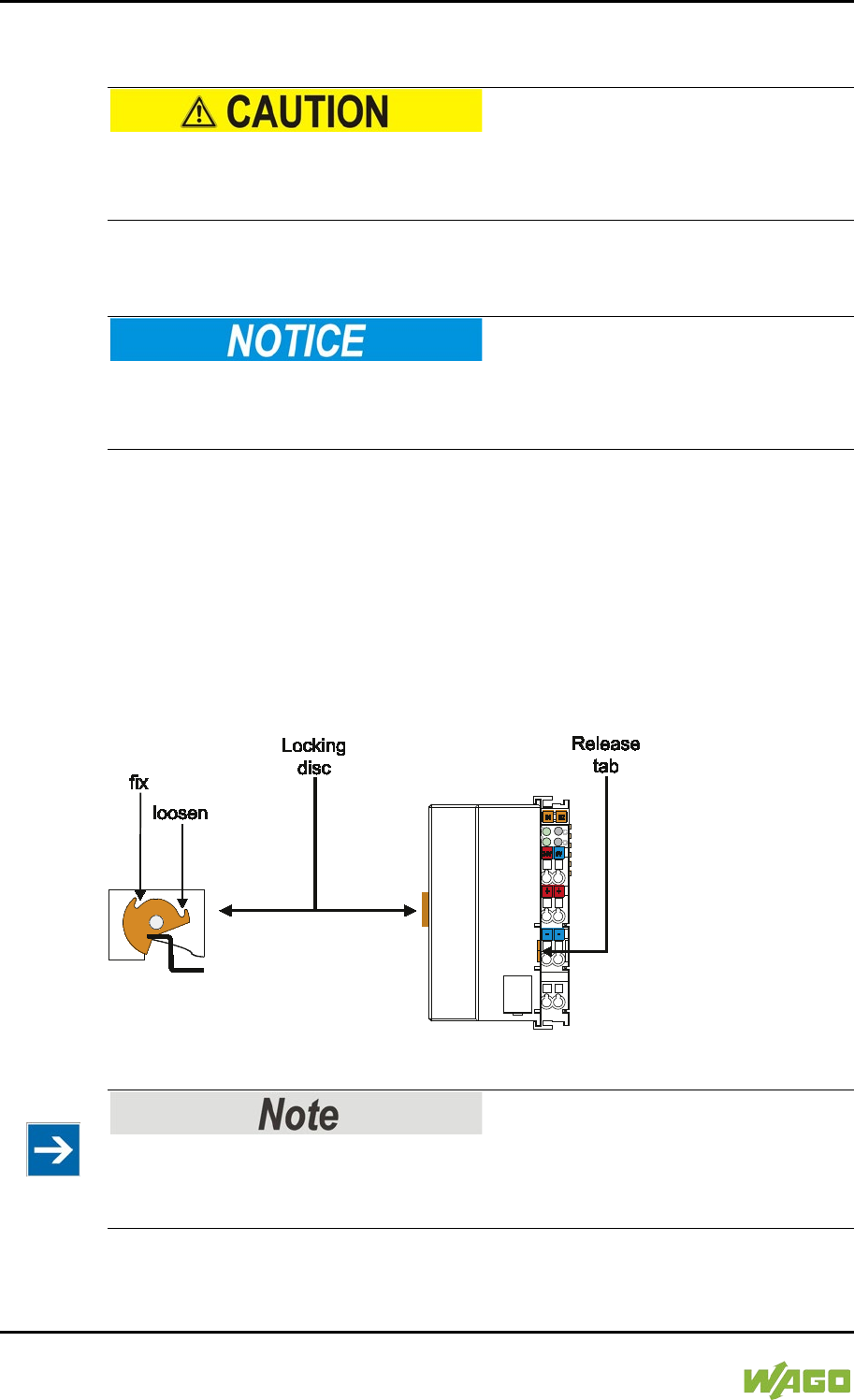
342 Removal WAGO-I/O-SYSTEM 750
750-8207 PFC200 CS 2ETH RS 3G
Manual
Draft version 1.2.1 from 2017-09-13, valid from FW Version 02.06.20(09)
14 Removal
Risk of injury due to sharp-edged blade contacts!
The blade contacts are sharp-edged. Handle the I/O module carefully to prevent
injury.
14.1 Removing Devices
Perform work on devices only if they are de-energized!
Working on energized devices can damage them. Therefore, turn off the power
supply before working on the devices.
14.1.1 Removing the Controller
1. Use a screwdriver blade to turn the locking disc until the nose of the locking
disc no longer engages behind the carrier rail.
2. Remove the controller from the assembly by pulling the release tab.
Electrical connections for data or power contacts to adjacent I/O modules are
disconnected when removing the controller.
Figure 121: Release Tab of Controller
Do not take the controller enclosure apart!
The enclosure sections are firmly joined. The feed-in section with the CAGE
CLAMP® connections cannot be separated from the other enclosure section.
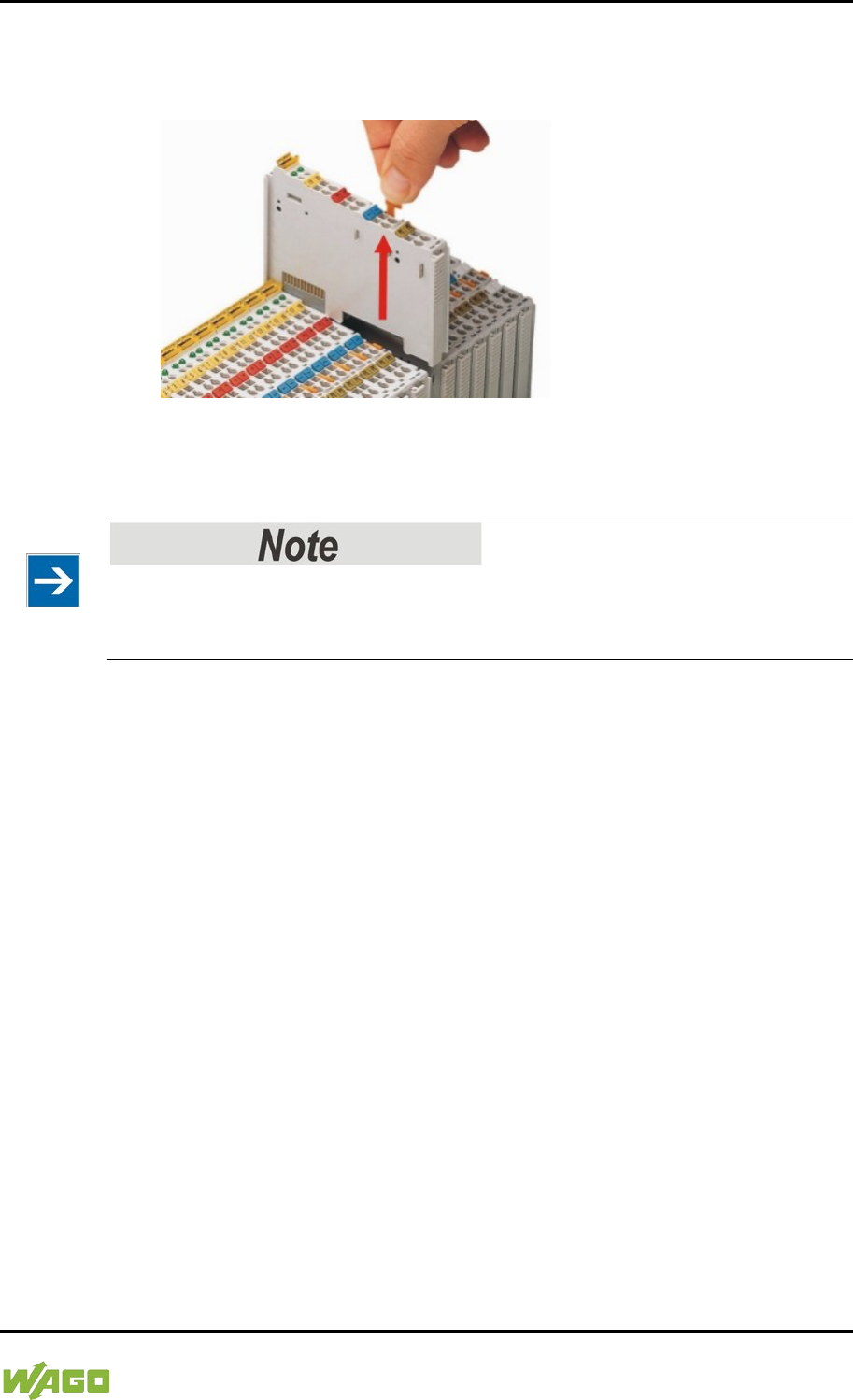
WAGO-I/O-SYSTEM 750 Removal 343
750-8207 PFC200 CS 2ETH RS 3G
Manual
Draft version 1.2.1 from 2017-09-13, valid from FW Version 02.06.20(09)
14.1.2 Removing the I/O Module
1. Remove the I/O module from the assembly by pulling the release tab.
Figure 122: Removing the I/O Module (Example)
Electrical connections for data or power jumper contacts are disconnected when
removing the I/O module.
Do not take the controller enclosure apart!
The enclosure sections are firmly joined. The feed-in section with the CAGE
CLAMP® connections cannot be separated from the other enclosure section.
344 Appendix WAGO-I/O-SYSTEM 750
750-8207 PFC200 CS 2ETH RS 3G
Manual
Draft version 1.2.1 from 2017-09-13, valid from FW Version 02.06.20(09)
15 Appendix
15.1 Structure of Process Data for the I/O Modules
The process image for the I/O modules on the internal data bus is built up word-
by-word in the controller (with word alignment). The internal mapping method for
data greater than one byte conforms to Intel formats.
The following section describes the representation for WAGO-I/O SYSTEM 750
(750 and 753 Series) I/O modules in the process image, as well as the
configuration of the process values.
Equipment damage due to incorrect address!
To prevent any damage to the device in the field you must always take the
process data for all previous byte or bit-oriented I/O modules into account when
addressing an I/O module at any position in the fieldbus node.
No direct access from fieldbus to the process image for I/O modules!
Any data that is required from the I/O module process image must be explicitly
mapped in
the CODESYS program to the data in the fieldbus process image and
vice versa! Direct access is not possible!

WAGO-I/O-SYSTEM 750 Appendix 345
750-8207 PFC200 CS 2ETH RS 3G
Manual
Draft version 1.2.1 from 2017-09-13, valid from FW Version 02.06.20(09)
15.1.1 Digital Input Modules
Digital input modules supply one bit of data per channel to specify the signal
state for the corresponding channel. These bits are mapped into the Input
Process Image.
Some digital modules have an additional diagnostic bit per channel in the Input
Process Image. The diagnostic bit is used for detecting faults that occur (e.g.,
wire breaks and/or short circuits).
When analog input modules are also present in the node, the digital data is
always appended after the analog data in the Input Process Image, grouped into
bytes.
15.1.1.1 1 Channel Digital Input Module with Diagnostics
750-435
Table 242: 1 Channel Digital Input Module with Diagnostics
Input Process Image
Bit 7
Bit 6
Bit 5
Bit 4
Bit 3
Bit 2
Bit 1
Bit 0
Diagnostic
bit
S 1
Data bit
DI 1
15.1.1.2 2 Channel Digital Input Modules
750-400, -401, -405, -406, -410, -411, -412, -427, -438, (and all variations),
753-400, -401, -405, -406, -410, -411, -412, -427
Table 243: 2 Channel Digital Input Modules
Input Process Image
Bit 7
Bit 6
Bit 5
Bit 4
Bit 3
Bit 2
Bit 1
Bit 0
Data bit
DI 2
Channel 2
Data bit
DI 1
Channel 1
15.1.1.3 2 Channel Digital Input Module with Diagnostics
750-419, -421, -424, -425,
753-421, -424, -425
Table 244: 2 Channel Digital Input Module with Diagnostics
Input Process Image
Bit 7
Bit 6
Bit 5
Bit 4
Bit 3
Bit 2
Bit 1
Bit 0
Diagnostic
bit S 2
Channel 2
Diagnostic
bit S 1
Channel 1
Data bit
DI 2
Channel 2
Data bit
DI 1
Channel 1

346 Appendix WAGO-I/O-SYSTEM 750
750-8207 PFC200 CS 2ETH RS 3G
Manual
Draft version 1.2.1 from 2017-09-13, valid from FW Version 02.06.20(09)
15.1.1.4 2 Channel Digital Input Module with Diagnostics and Output Process
Data
750-418,
753-418
The digital input module supplies a diagnostic and acknowledge bit for each input
channel. If a fault condition occurs, the diagnostic bit is set. After the fault
condition is cleared, an acknowledge bit must be set to re-activate the input. The
diagnostic data and input data bit is mapped in the Input Process Image, while
the acknowledge bit is in the Output Process Image.
Table 245: 2 Channel Digital Input Module with Diagnostics and Output Process Data
Input Process Image
Bit 7
Bit 6
Bit 5
Bit 4
Bit 3
Bit 2
Bit 1
Bit 0
Diagnostic bit
S 2
Channel 2
Diagnostic bit
S 1
Channel 1
Data bit
DI 2
Channel 2
Data bit
DI 1
Channel 1
Output Process Image
Bit 7
Bit 6
Bit 5
Bit 4
Bit 3
Bit 2
Bit 1
Bit 0
Acknowledge-
ment bit Q 2
Channel 2
Acknowledge-
ment bit Q 1
Channel 1
0 0
15.1.1.5 4 Channel Digital Input Modules
750-402, -403, -408, -409, -414, -415, -422, -423, -428, -432, -433, -1420, -1421,
-1422, -1423
753-402, -403, -408, -409, -415, -422, -423, -428, -432, -433, -440
Table 246: 4 Channel Digital Input Modules
Input Process Image
Bit 7
Bit 6
Bit 5
Bit 4
Bit 3
Bit 2
Bit 1
Bit 0
Data bit
DI 4
Channel 4
Data bit
DI 3
Channel 3
Data bit
DI 2
Channel 2
Data bit
DI 1
Channel 1
15.1.1.6 8 Channel Digital Input Modules
750-430, -431, -436, -437, -1415, -1416, -1417, -1418
753-430, -431, -434
Table 247: 8 Channel Digital Input Modules
Input Process Image
Bit 7
Bit 6
Bit 5
Bit 4
Bit 3
Bit 2
Bit 1
Bit 0
Data bit DI
8
Channel 8
Data bit
DI 7
Channel 7
Data bit
DI 6
Channel 6
Data bit
DI 5
Channel 5
Data bit
DI 4
Channel 4
Data bit
DI 3
Channel 3
Data bit
DI 2
Channel 2
Data bit
DI 1
Channel 1

WAGO-I/O-SYSTEM 750 Appendix 347
750-8207 PFC200 CS 2ETH RS 3G
Manual
Draft version 1.2.1 from 2017-09-13, valid from FW Version 02.06.20(09)
15.1.1.7 8 Channel Digital Input Module PTC with Diagnostics and Output
Process Data
750-1425
The digital input module PTC provides via one logical channel 2 byte for the input
and output process image.
The signal state of PTC inputs DI1 … DI8 is transmitted to the fieldbus
coupler/controller via input data byte D0.
The fault conditions are transmitted via input data byte D1.
The channels 1 … 8 are switched on or off via the output data byte D1. The
output data byte D0 is reserved and always has the value “0“.
Table 248: 8 Channel Digital Input Module PTC with Diagnostics and Output Process Data
Input Process Image
Input Byte D0
Input Byte D1
Bit 7
Bit 6
Bit 5
Bit 4
Bit 3
Bit 2
Bit 1
Bit 0
Bit 7
Bit 6
Bit 5
Bit 4
Bit 3
Bit 2
Bit 1
Bit 0
Signal
status
DI 8
Chan-
nel 8
Signal
status
DI 7
Chan-
nel 7
Signal
status
DI 6
Chan-
nel 6
Signal
status
DI 5
Chan-
nel 5
Signal
status
DI 4
Chan-
nel 4
Signal
status
DI 3
Chan-
nel 3
Signal
status
DI 2
Chan-
nel 2
Signal
status
DI 1
Chan-
nel 1
Wire
break/
short
circuit
DB/KS
8
Chan-
nel 8
Wire
break/
short
circuit
DB/KS
7
Chan-
nel 7
Wire
break/
short
circuit
DB/KS
6
Chan-
nel 6
Wire
break/
short
circuit
DB/KS
5
Chan-
nel 5
Wire
break/
short
circuit
DB/KS
4
Chan-
nel 4
Wire
break/
short
circuit
DB/KS
3
Chan-
nel 3
Wire
break/
short
circuit
DB/KS
2
Chan-
nel 2
Wire
break/
short
circuit
DB/KS
1
Chan-
nel 1
Output Process Image
Output Byte D0
Output Byte D1
Bit 7
Bit 6
Bit 5
Bit 4
Bit 3
Bit 2
Bit 1
Bit 0
Bit 7
Bit 6
Bit 5
Bit 4
Bit 3
Bit 2
Bit 1
Bit 0
0 0 0 0 0 0 0 0
DI
Off 8
Chan-
nel 8
0:
Chan-
nel
ON
1:
Chan-
nel
OFF
DI
Off 7
Chan-
nel 7
0:
Chan-
nel
ON
1:
Chan-
nel
OFF
DI
Off 6
Chan-
nel 6
0:
Chan-
nel
ON
1:
Chan-
nel
OFF
DI
Off 5
Chan-
nel 5
0:
Chan-
nel
ON
1:
Chan-
nel
OFF
DI
Off 4
Chan-
nel 4
0:
Chan-
nel
ON
1:
Chan-
nel
OFF
DI
Off 3
Chan-
nel 3
0:
Chan-
nel
ON
1:
Chan-
nel
OFF
DI
Off 2
Chan-
nel 2
0:
Chan-
nel
ON
1:
Chan-
nel
OFF
DI
Off 1
Chan-
nel 1
0:
Chan-
nel
ON
1:
Chan-
nel
OFF
15.1.1.8 16 Channel Digital Input Modules
750-1400, -1402, -1405, -1406, -1407
Table 249: 16 Channel Digital Input Modules
Input Process Image
Bit 15
Bit 14
Bit 13
Bit 12
Bit 11
Bit 10
Bit 9
Bit 8
Bit 7
Bit 6
Bit 5
Bit 4
Bit 3
Bit 2
Bit 1
Bit 0
Data
bit
DI 16
Chann
el 16
Data
bit
DI 15
Chan
nel 15
Data
bit
DI 14
Chan
nel 14
Data
bit
DI 13
Chan
nel 13
Data
bit
DI 12
Chan
nel 12
Data
bit
DI 11
Chan
nel 11
Data
bit
DI 10
Chann
el 10
Data
bit
DI 9
Chan
nel 9
Data
bit DI
8
Chan
nel 8
Data
bit
DI 7
Chan
nel 7
Data
bit
DI 6
Chan
nel 6
Data
bit
DI 5
Chan
nel 5
Data
bit
DI 4
Chan
nel 4
Data
bit
DI 3
Chan
nel 3
Data
bit
DI 2
Chan
nel 2
Data
bit
DI 1
Chan
nel 1

348 Appendix WAGO-I/O-SYSTEM 750
750-8207 PFC200 CS 2ETH RS 3G
Manual
Draft version 1.2.1 from 2017-09-13, valid from FW Version 02.06.20(09)
15.1.2 Digital Output Modules
Digital output modules use one bit of data per channel to control the output of the
corresponding channel. These bits are mapped into the Output Process Image.
Some digital modules have an additional diagnostic bit per channel in the Input
Process Image. The diagnostic bit is used for detecting faults that occur (e.g.,
wire breaks and/or short circuits). For modules with diagnostic bit is set, also the
data bits have to be evaluated.
When analog output modules are also present in the node, the digital image data
is always appended after the analog data in the Output Process Image, grouped
into bytes.
15.1.2.1 1 Channel Digital Output Module with Input Process Data
750-523
The digital output modules deliver 1 bit via a process value Bit in the output
process image, which is illustrated in the input process image. This status image
shows "manual mode".
Table 250: 1 Channel Digital Output Module with Input Process Data
Input Process Image
Bit 7
Bit 6
Bit 5
Bit 4
Bit 3
Bit 2
Bit 1
Bit 0
not used
Status bit
“Manual
Operation“
Output Process Image
Bit 7
Bit 6
Bit 5
Bit 4
Bit 3
Bit 2
Bit 1
Bit 0
not used
controls
DO 1
Channel 1
15.1.2.2 2 Channel Digital Output Modules
750-501, -502, -509, -512, -513, -514, -517, -535, (and all variations),
753-501, -502, -509, -512, -513, -514, -517
Table 251: 2 Channel Digital Output Modules
Output Process Image
Bit 7
Bit 6
Bit 5
Bit 4
Bit 3
Bit 2
Bit 1
Bit 0
controls
DO 2
Channel 2
controls
DO 1
Channel 1

WAGO-I/O-SYSTEM 750 Appendix 349
750-8207 PFC200 CS 2ETH RS 3G
Manual
Draft version 1.2.1 from 2017-09-13, valid from FW Version 02.06.20(09)
15.1.2.3 2 Channel Digital Input Modules with Diagnostics and Input Process
Data
750-507 (-508), -522,
753-507
The digital output modules have a diagnostic bit for each output channel. When
an output fault condition occurs (i.e., overload, short circuit, or broken wire), a
diagnostic bit is set. The diagnostic data is mapped into the Input Process Image,
while the output control bits are in the Output Process Image.
Table 252: 2 Channel Digital Input Modules with Diagnostics and Input Process Data
Input Process Image
Bit 7
Bit 6
Bit 5
Bit 4
Bit 3
Bit 2
Bit 1
Bit 0
Diagnostic
bit S 2
Channel 2
Diagnostic bit
S 1
Channel 1
Output Process Image
Bit 7
Bit 6
Bit 5
Bit 4
Bit 3
Bit 2
Bit 1
Bit 0
controls
DO 2
Channel 2
controls
DO 1
Channel 1
750-506,
753-506
The digital output module has 2-bits of diagnostic information for each output
channel. The 2-bit diagnostic information can then be decoded to determine the
exact fault condition of the module (i.e., overload, a short circuit, or a broken
wire). The 4-bits of diagnostic data are mapped into the Input Process Image,
while the output control bits are in the Output Process Image.
Table 253: 2 Channel Digital Input Modules with Diagnostics and Input Process Data 75x-506
Input Process Image
Bit 7
Bit 6
Bit 5
Bit 4
Bit 3
Bit 2
Bit 1
Bit 0
Diagnostic bit
S 3
Channel 2
Diagnostic bit
S 2
Channel 2
Diagnostic
bit S 1
Channel 1
Diagnostic bit
S 0
Channel 1
Diagnostic bits S1/S0, S3/S2: = ‘00’ standard mode
Diagnostic bits S1/S0, S3/S2: = ‘01’
no connected load/short circuit against +24 V
Diagnostic bits S1/S0, S3/S2: = ‘10’ Short circuit to ground/overload
Output Process Image
Bit 7
Bit 6
Bit 5
Bit 4
Bit 3
Bit 2
Bit 1
Bit 0
not used not used
controls
DO 2
Channel 2
controls
DO 1
Channel 1

350 Appendix WAGO-I/O-SYSTEM 750
750-8207 PFC200 CS 2ETH RS 3G
Manual
Draft version 1.2.1 from 2017-09-13, valid from FW Version 02.06.20(09)
15.1.2.4 4 Channel Digital Output Modules
750-504, -516, -519, -531,
753-504, -516, -531, -540
Table 254: 4 Channel Digital Output Modules
Output Process Image
Bit 7
Bit 6
Bit 5
Bit 4
Bit 3
Bit 2
Bit 1
Bit 0
controls
DO 4
Channel 4
controls
DO 3
Channel 3
controls
DO 2
Channel 2
controls
DO 1
Channel 1
15.1.2.5 4 Channel Digital Output Modules with Diagnostics and Input
Process Data
750-532
The digital output modules have a diagnostic bit for each output channel. When
an output fault condition occurs (i.e., overload, short circuit, or broken wire), a
diagnostic bit is set. The diagnostic data is mapped into the Input Process Image,
while the output control bits are in the Output Process Image.
Table 255: 4 Channel Digital Output Modules with Diagnostics and Input Process Data
Input Process Image
Bit 7
Bit 6
Bit 5
Bit 4
Bit 3
Bit 2
Bit 1
Bit 0
Diagnostic
bit
S 4
Channel 4
Diagnostic
bit
S 3
Channel 3
Diagnostic
bit
S 2
Channel 2
Diagnostic bit
S 1
Channel 1
Diagnostic bit S = ‘0’ no Error
Diagnostic bit S = ‘1’ overload, short circuit, or broken wire
Output Process Image
Bit 7
Bit 6
Bit 5
Bit 4
Bit 3
Bit 2
Bit 1
Bit 0
controls
DO 4
Channel 4
controls
DO 3
Channel 3
controls
DO 2
Channel 2
controls
DO 1
Channel 1
15.1.2.6 8 Channel Digital Output Module
750-530, -536, -1515, -1516
753-530, -534
Table 256: 8 Channel Digital Output Module
Output Process Image
Bit 7
Bit 6
Bit 5
Bit 4
Bit 3
Bit 2
Bit 1
Bit 0
controls
DO 8
Channel 8
controls
DO 7
Channel 7
controls
DO 6
Channel 6
controls
DO 5
Channel 5
controls
DO 4
Channel 4
controls
DO 3
Channel 3
controls
DO 2
Channel 2
controls
DO 1
Channel 1

WAGO-I/O-SYSTEM 750 Appendix 351
750-8207 PFC200 CS 2ETH RS 3G
Manual
Draft version 1.2.1 from 2017-09-13, valid from FW Version 02.06.20(09)
15.1.2.7 8 Channel Digital Output Modules with Diagnostics and Input
Process Data
750-537
The digital output modules have a diagnostic bit for each output channel. When
an output fault condition occurs (i.e., overload, short circuit, or broken wire), a
diagnostic bit is set. The diagnostic data is mapped into the Input Process Image,
while the output control bits are in the Output Process Image.
Table 257: 8 Channel Digital Output Modules with Diagnostics and Input Process Data
Input Process Image
Bit 7
Bit 6
Bit 5
Bit 4
Bit 3
Bit 2
Bit 1
Bit 0
Diagnostic
bit
S 8
Channel 8
Diagnostic
bit
S 7
Channel 7
Diagnostic
bit
S 6
Channel 6
Diagnostic
bit
S 5
Channel 5
Diagnostic
bit
S 4
Channel 4
Diagnostic
bit
S 3
Channel 3
Diagnostic
bit
S 2
Channel 2
Diagnostic
bit
S 1
Channel 1
Diagnostic bit S = ‘0’ no Error
Diagnostic bit S = ‘1’ overload, short circuit, or broken wire
Output Process Image
Bit 7
Bit 6
Bit 5
Bit 4
Bit 3
Bit 2
Bit 1
Bit 0
controls
DO 8
Channel 8
controls
DO 7
Channel 7
controls
DO 6
Channel 6
controls
DO 5
Channel 5
controls
DO 4
Channel 4
controls
DO 3
Channel 3
controls
DO 2
Channel 2
controls
DO 1
Channel 1
15.1.2.8 16 Channel Digital Output Modules
750-1500, -1501, -1504, -1505
Table 258: 16 Channel Digital Output Modules
Output Process Image
Bit 15
Bit 14
Bit 13
Bit 12
Bit 11
Bit 10
Bit 9
Bit 8
Bit 7
Bit 6
Bit 5
Bit 4
Bit 3
Bit 2
Bit 1
Bit 0
controls
DO 16
Channel
16
controls
DO 15
Channe
l 15
controls
DO 14
Channe
l 14
controls
DO 13
Channe
l 13
controls
DO 12
Channe
l 12
controls
DO 11
Channe
l 11
controls
DO 10
Channel
10
controls
DO 9
Channe
l 9
controls
DO 8
Channe
l 8
controls
DO 7
Channe
l 7
controls
DO 6
Channe
l 6
controls
DO 5
Channe
l 5
controls
DO 4
Channe
l 4
controls
DO 3
Channe
l 3
controls
DO 2
Channe
l 2
controls
DO 1
Channe
l 1

352 Appendix WAGO-I/O-SYSTEM 750
750-8207 PFC200 CS 2ETH RS 3G
Manual
Draft version 1.2.1 from 2017-09-13, valid from FW Version 02.06.20(09)
15.1.2.9 8 Channel Digital Input/Output Modules
750-1502, -1506
Table 259: 8 Channel Digital Input/Output Modules
Input Process Image
Bit 7
Bit 6
Bit 5
Bit 4
Bit 3
Bit 2
Bit 1
Bit 0
Data bit DI
8
Channel 8
Data bit
DI 7
Channel 7
Data bit
DI 6
Channel 6
Data bit
DI 5
Channel 5
Data bit
DI 4
Channel 4
Data bit
DI 3
Channel 3
Data bit
DI 2
Channel 2
Data bit
DI 1
Channel 1
Output Process Image
Bit 7
Bit 6
Bit 5
Bit 4
Bit 3
Bit 2
Bit 1
Bit 0
controls
DO 8
Channel 8
controls
DO 7
Channel 7
controls
DO 6
Channel 6
controls
DO 5
Channel 5
controls
DO 4
Channel 4
controls
DO 3
Channel 3
controls
DO 2
Channel 2
controls
DO 1
Channel 1
WAGO-I/O-SYSTEM 750 Appendix 353
750-8207 PFC200 CS 2ETH RS 3G
Manual
Draft version 1.2.1 from 2017-09-13, valid from FW Version 02.06.20(09)
15.1.3 Analog Input Modules
The analog input modules provide 16-bit measured data and 8 control/status bits
per channel.
The controller only uses the 8 control/status bits internally for
configuration/parameterization (e.g., via WAGO-I/O-CHECK).
Therefore, only the 16-bit measurement values for each channel are in Intel
format and are mapped by word in the input process image for the controller.
When digital input modules are also present in the node, the analog input data is
always mapped into the Input Process Image in front of the digital data.
Information on the structure of control and status bytes
For detailed information on the structure of a particular I/O module’s
control/status bytes, please refer to that module’s manual. Manuals for each
module can be found on the Internet at www.wago.com.
15.1.3.1 1 Channel Analog Input Modules
750-491, (and all variations)
Table 260: 1 Channel Analog Input Modules
Input Process Image
Offset
Byte Destination
Description
High Byte
Low Byte
0
D1
D0
Measured Value UD
1
D3
D2
Measured Value Uref
15.1.3.2 2 Channel Analog Input Modules
750-452, -454, -456, -461, -462, -465, -466, -467, -469, -472, -474, -475, 476, -
477, -478, -479, -480, -481, -483, -485, -492, (and all variations),
753-452, -454, -456, -461, -465, -466, -467, -469, -472, -474, -475, 476, -477,
478, -479, -483, -492, (and all variations)
Table 261: 2 Channel Analog Input Modules
Input Process Image
Offset
Byte Destination
Description
High Byte
Low Byte
0
D1
D0
Measured Value Channel 1
1
D3
D2
Measured Value Channel 2

354 Appendix WAGO-I/O-SYSTEM 750
750-8207 PFC200 CS 2ETH RS 3G
Manual
Draft version 1.2.1 from 2017-09-13, valid from FW Version 02.06.20(09)
15.1.3.3 4 Channel Analog Input Modules
750-450, -453, -455, -457, -459, -460, -468, (and all variations),
753-453, -455, -457, -459
Table 262: 4 Channel Analog Input Modules
Input Process Image
Offset
Byte Destination
Description
High Byte
Low Byte
0
D1
D0
Measured Value Channel 1
1
D3
D2
Measured Value Channel 2
2
D5
D4
Measured Value Channel 3
3
D7
D6
Measured Value Channel 4
WAGO-I/O-SYSTEM 750 Appendix 355
750-8207 PFC200 CS 2ETH RS 3G
Manual
Draft version 1.2.1 from 2017-09-13, valid from FW Version 02.06.20(09)
15.1.3.4 3-Phase Power Measurement Module
750-493
The above Analog Input Modules have a total of 9 bytes of user data in both the
Input and Output Process Image (6 bytes of data and 3 bytes of control/status).
The following tables illustrate the Input and Output Process Image, which has a
total of 6 words mapped into each image.
Word alignment is applied.
Table 263: 3-Phase Power Measurement Module
Input Process Image
Offset
Byte Destination
Description
High Byte
Low Byte
0
-
S0
Status byte 0
1
D1
D0
Input data word 1
2
-
S1
Status byte 1
3
D3
D2
Input data word 2
4
-
S2
Status byte 2
5
D5
D4
Input data word 3
Output Process Image
Offset
Byte Destination
Description
High Byte
Low Byte
0
-
C0
Control byte 0
1
D1
D0
Output data word 1
2
-
C1
Control byte 1
3
D3
D2
Output data word 2
4
-
C2
Control byte 2
5
D5
D4
Output data word 3
15.1.3.5 8 Channel Analog Input Modules
750-451
Table 264: 8 Channel Analog Input Modules
Input Process Image
Offset
Byte Destination
Description
High Byte
Low Byte
0
D1
D0
Measured Value Channel 1
1
D3
D2
Measured Value Channel 2
2
D5
D4
Measured Value Channel 3
3
D7
D6
Measured Value Channel 4
4
D9
D8
Measured Value Channel 5
5
D11
D10
Measured Value Channel 6
6
D13
D12
Measured Value Channel 7
7
D15
D14
Measured Value Channel 8
356 Appendix WAGO-I/O-SYSTEM 750
750-8207 PFC200 CS 2ETH RS 3G
Manual
Draft version 1.2.1 from 2017-09-13, valid from FW Version 02.06.20(09)
15.1.4 Analog Output Modules
The analog output modules provide 16-bit output values and 8 control/status bits
per channel.
The controller only uses the 8 control/status bits internally for
configuration/parameterization (e.g., via WAGO-I/O-CHECK).
Therefore, only the 16-bit measurement values for each channel are in Intel
format and are mapped by word in the output process image for the controller.
When digital output modules are also present in the node, the analog output data
is always mapped into the Output Process Image in front of the digital data.
Information on the structure of control and status bytes
For detailed information on the structure of a particular I/O module’s
control/status bytes, please refer to that module’s manual. Manuals for each
module can be found on the Internet at www.wago.com.
15.1.4.1 2 Channel Analog Output Modules
750-550, -552, -554, -556, -560, -562, 563, -585, (and all variations),
753-550, -552, -554, -556
Table 265: 2 Channel Analog Output Modules
Output Process Image
Offset
Byte Destination
Description
High Byte
Low Byte
0
D1
D0
Output Value Channel 1
1
D3
D2
Output Value Channel 2
15.1.4.2 4 Channel Analog Output Modules
750-553, -555, -557, -559,
753-553, -555, -557, -559
Table 266: 4 Channel Analog Output Modules
Output Process Image
Offset
Byte Destination
Description
High Byte
Low Byte
0
D1
D0
Output Value Channel 1
1
D3
D2
Output Value Channel 2
2
D5
D4
Output Value Channel 3
3
D7
D6
Output Value Channel 4
WAGO-I/O-SYSTEM 750 Appendix 357
750-8207 PFC200 CS 2ETH RS 3G
Manual
Draft version 1.2.1 from 2017-09-13, valid from FW Version 02.06.20(09)
15.1.5 Specialty Modules
WAGO has a host of Specialty I/O modules that perform various functions. With
individual modules beside the data bytes also the control/status byte is mapped
in the process image.
The control/status byte is required for the bidirectional data exchange of the
module with the higher-ranking control system. The control byte is transmitted
from the control system to the module and the status byte from the module to the
control system.
This allows, for example, setting of a counter with the control byte or displaying of
overshooting or undershooting of the range with the status byte.
The control/status byte always is in the process image in the Low byte.
Information to the structure of the Control/Status byte
For detailed information about the structure of a particular module’s control/status
byte, please refer to that module’s manual. Manuals for each module can be
found on the Internet under: www.wago.com.
15.1.5.1 Counter Modules
750-404, (and all variations except of /000-005),
753-404, (and variation /000-003)
The above Counter Modules have a total of 5 bytes of user data in both the Input
and Output Process Image (4 bytes of counter data and 1 byte of control/status).
The counter value is supplied as 32 bits. The following tables illustrate the Input
and Output Process Image, which has a total of 3 words mapped into each
image. Word alignment is applied.
Table 267: Counter Modules 750-404, (and all variations except of /000-005),
753
-404, (and variation /000-003)
Input Process Image
Offset
Byte Destination
Description
High Byte
Low Byte
0
-
S
Status byte
1
D1
D0
Counter value
2
D3
D2
Output Process Image
Offset
Byte Destination
Description
High Byte
Low Byte
0
-
C
Control byte
1
D1
D0
Counter setting value
2
D3
D2
358 Appendix WAGO-I/O-SYSTEM 750
750-8207 PFC200 CS 2ETH RS 3G
Manual
Draft version 1.2.1 from 2017-09-13, valid from FW Version 02.06.20(09)
750-404/000-005
The above Counter Modules have a total of 5 bytes of user data in both the Input
and Output Process Image (4 bytes of counter data and 1 byte of control/ status).
The two counter values are supplied as 16 bits. The following tables illustrate the
Input and Output Process Image, which has a total of 3 words mapped into each
image. Word alignment is applied.
Table 268: Counter Modules 750-404/000-005
Input Process Image
Offset
Byte Destination
Description
High Byte
Low Byte
0
-
S
Status byte
1
D1
D0
Counter Value of Counter 1
2
D3
D2
Counter Value of Counter 2
Output Process Image
Offset
Byte Destination
Description
High Byte
Low Byte
0
-
C
Control byte
1
D1
D0
Counter Setting Value of Counter 1
2
D3
D2
Counter Setting Value of Counter 2
750-638,
753-638
The above Counter Modules have a total of 6 bytes of user data in both the Input
and Output Process Image (4 bytes of counter data and 2 bytes of
control/status). The two counter values are supplied as 16 bits. The following
tables illustrate the Input and Output Process Image, which has a total of 4 words
mapped into each image. Word alignment is applied.
Table 269: Counter Modules 750-638, 753-638
Input Process Image
Offset
Byte Destination
Description
High Byte
Low Byte
0
-
S0
Status byte von Counter 1
1
D1
D0
Counter Value von Counter 1
2
-
S1
Status byte von Counter 2
3
D3
D2
Counter Value von Counter 2
Output Process Image
Offset
Byte Destination
Description
High Byte
Low Byte
0
-
C0
Control byte von Counter 1
1
D1
D0
Counter Setting Value von Counter 1
2
-
C1
Control byte von Counter 2
3
D3
D2
Counter Setting Value von Counter 2
WAGO-I/O-SYSTEM 750 Appendix 359
750-8207 PFC200 CS 2ETH RS 3G
Manual
Draft version 1.2.1 from 2017-09-13, valid from FW Version 02.06.20(09)
15.1.5.2 Pulse Width Modules
750-511, (and all variations /xxx-xxx)
The above Pulse Width modules have a total of 6 bytes of user data in both the
Input and Output Process Image (4 bytes of channel data and 2 bytes of control/
status). The two channel values are supplied as 16 bits. Each channel has its
own control/status byte. The following table illustrates the Input and Output
Process Image, which has a total of 4 words mapped into each image. Word
alignment is applied.
Table 270: Pulse Width Modules 750-511, /xxx-xxx
Input and Output Process
Offset
Byte Destination
Description
High Byte
Low Byte
0
-
C0/S0
Control/Status byte of Channel 1
1
D1
D0
Data Value of Channel 1
2
-
C1/S1
Control/Status byte of Channel 2
3
D3
D2
Data Value of Channel 2
15.1.5.3 Serial Interface Modules with alternative Data Format
750-650, (and the variations /000-002, -004, -006, -009, -010, -011, -012, -013),
750-651, (and the variations /000-001, -002, -003),
750-653, (and the variations /000-002, -007),
753-650, -653
The process image of the / 003-000-variants depends on the parameterized
operating mode!
With the freely parameterizable variations /003 000 of the serial interface
modules, the desired operation mode can be set. Dependent on it, the process
image of these modules is then the same, as from the appropriate variation.
The above Serial Interface Modules with alternative data format have a total of 4
bytes of user data in both the Input and Output Process Image (3 bytes of serial
data and 1 byte of control/status). The following table illustrates the Input and
Output Process Image, which have a total of 2 words mapped into each image.
Word alignment is applied.
Table 271: Serial Interface Modules with alternative Data Format
Input and Output Process Image
Offset
Byte Destination
Description
High Byte
Low Byte
0 D0 C/S Data byte
Control/status
byte
1
D2
D1
Data bytes
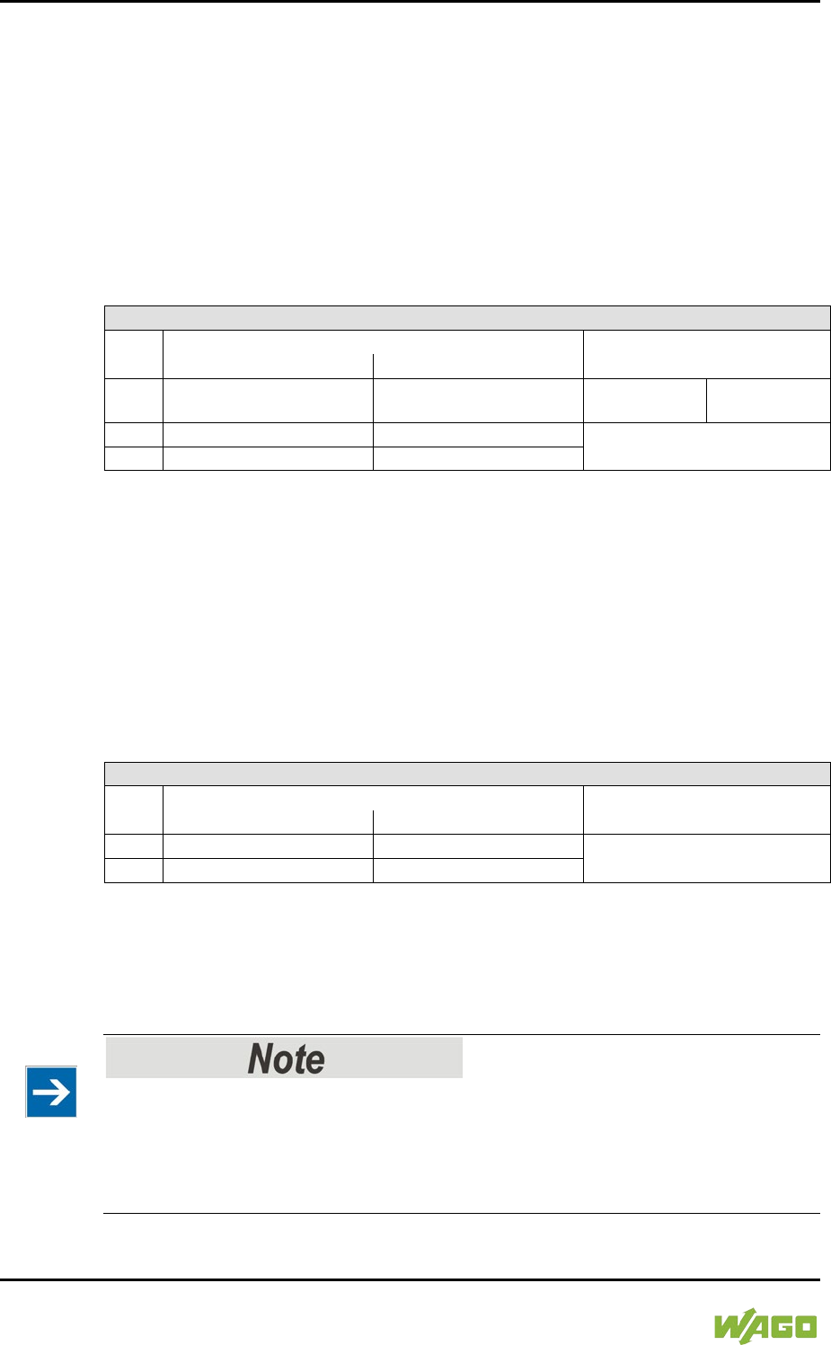
360 Appendix WAGO-I/O-SYSTEM 750
750-8207 PFC200 CS 2ETH RS 3G
Manual
Draft version 1.2.1 from 2017-09-13, valid from FW Version 02.06.20(09)
15.1.5.4 Serial Interface Modules with Standard Data Format
750-650/000-001, -014, -015, -016
750-653/000-001, -006
The above Serial Interface Modules with Standard Data Format have a total of 6
bytes of user data in both the Input and Output Process Image (5 bytes of serial
data and 1 byte of control/status). The following table illustrates the Input and
Output Process Image, which have a total of 3 words mapped into each image.
Word alignment is applied.
Table 272: Serial Interface Modules with Standard Data Format
Input and Output Process Image
Offset
Byte Destination
Description
High Byte
Low Byte
0 D0 C/S Data byte
Control/status
byte
1
D2
D1
Data bytes
2
D4
D3
15.1.5.5 Data Exchange Module
750-654, (and the variation /000-001)
The Data Exchange modules have a total of 4 bytes of user data in both the Input
and Output Process Image. The following tables illustrate the Input and Output
Process Image, which has a total of 2 words mapped into each image.
Word alignment is applied.
Table 273: Data Exchange Module
Input and Output Process Image
Offset
Byte Destination
Description
High Byte
Low Byte
0
D1
D0
Data bytes
1
D3
D2
15.1.5.6 SSI Transmitter Interface Modules
750-630 (and all variations)
The process image of the / 003-000-variants depends on the parameterized
operating mode!
The operating mode of the configurable /003-000 I/O module versions can be
set. Based on the operating mode, the process image of these I/O modules is
then the same as that of the respective version.
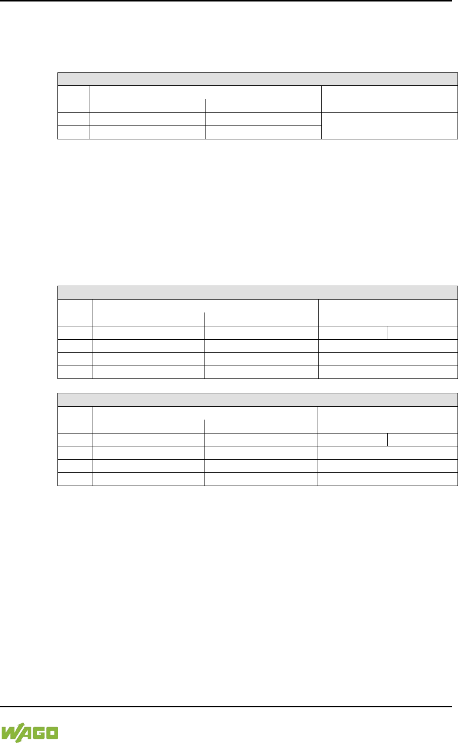
WAGO-I/O-SYSTEM 750 Appendix 361
750-8207 PFC200 CS 2ETH RS 3G
Manual
Draft version 1.2.1 from 2017-09-13, valid from FW Version 02.06.20(09)
The above SSI Transmitter Interface modules have a total of 4 bytes of user data
in the Input Process Image, which has 2 words mapped into the image.
Word alignment is applied.
Table 274: SSI Transmitter Interface Modules
Input Process Image
Offset
Byte Destination
Description
High Byte
Low Byte
0
D1
D0
Data bytes
1
D3
D2
15.1.5.7 Incremental Encoder Interface Modules
750-631/000-004, -010, -011
The above Incremental Encoder Interface modules have 5 bytes of input data
and 3 bytes of output data. The following tables illustrate the Input and Output
Process Image, which have 4 words into each image. Word alignment is applied.
Table 275: Incremental Encoder Interface Modules 750-631/000-004, --010, -011
Input Process Image
Offset
Byte Destination
Description
High Byte
Low Byte
0
-
S
not used
Status byte
1
D1
D0
Counter word
2
-
-
not used
3
D4
D3
Latch word
Output Process Image
Offset
Byte Destination
Description
High Byte
Low Byte
0
-
C
not used
Control byte
1
D1
D0
Counter setting word
2
-
-
not used
3
-
-
not used
750-634
The above Incremental Encoder Interface module has 5 bytes of input data (6
bytes in cycle duration measurement mode) and 3 bytes of output data. The
following tables illustrate the Input and Output Process Image, which has 4 words
mapped into each image. Word alignment is applied.
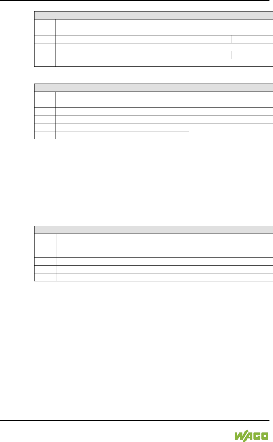
362 Appendix WAGO-I/O-SYSTEM 750
750-8207 PFC200 CS 2ETH RS 3G
Manual
Draft version 1.2.1 from 2017-09-13, valid from FW Version 02.06.20(09)
Table 276: Incremental Encoder Interface Modules 750-634
Input Process Image
Offset
Byte Destination
Description
High Byte
Low Byte
0
-
S
not used
Status byte
1
D1
D0
Counter word
2
-
(D2) *)
not used
(Periodic time)
3
D4
D3
Latch word
*) If cycle duration measurement mode is enabled in the control byte, the cycle duration is
given as a 24-bit value that is stored in D2 together with D3/D4.
Output Process Image
Offset
Byte Destination
Description
High Byte
Low Byte
0
-
C
not used
Control byte
1
D1
D0
Counter setting word
2
-
-
not used
3
-
-
750-637
The above Incremental Encoder Interface Module has a total of 6 bytes of user
data in both the Input and Output Process Image (4 bytes of encoder data and 2
bytes of control/status). The following table illustrates the Input and Output
Process Image, which have 4 words mapped into each image. Word alignment is
applied.
Table 277: Incremental Encoder Interface Modules 750-637
Input and Output Process Image
Offset
Byte Destination
Description
High Byte
Low Byte
0
-
C0/S0
Control/Status byte of Channel 1
1
D1
D0
Data Value of Channel 1
2
-
C1/S1
Control/Status byte of Channel 2
3
D3
D2
Data Value of Channel 2

WAGO-I/O-SYSTEM 750 Appendix 363
750-8207 PFC200 CS 2ETH RS 3G
Manual
Draft version 1.2.1 from 2017-09-13, valid from FW Version 02.06.20(09)
750-635,
753-635
The above Digital Pulse Interface module has a total of 4 bytes of user data in
both the Input and Output Process Image (3 bytes of module data and 1 byte of
control/status). The following table illustrates the Input and Output Process
Image, which have 2 words mapped into each image. Word alignment is applied.
Table 278: Digital Pulse Interface Modules 750-635
Input and Output Process Image
Offset
Byte Destination
Description
High Byte
Low Byte
0 D0 C0/S0 Data byte
Control/status
byte
1
D2
D1
Data bytes
15.1.5.8 DC-Drive Controller
750-636
The DC-Drive Controller maps 6 bytes into both the input and output process
image. The data sent and received are stored in up to 4 input and output bytes
(D0 ... D3). Two control bytes (C0, C1) and two status bytes (S0/S1) are used to
control the I/O module and the drive.
In addition to the position data in the input process image (D0 … D3), it is
possible to display extended status information (S2 … S5). Then the three control
bytes (C1 … C3) and status bytes (S1 … S3) are used to control the data flow.
Bit 3 of control byte C1 (C1.3) is used to switch between the process data and
the extended status bytes in the input process image (Extended Info_ON). Bit 3
of status byte S1 (S1.3) is used to acknowledge the switching process.
Table 279: DC-Drive Controller 750-636
Input Process Image
Offset
Byte Destination
Description
High Byte
Low Byte
0
S1
S0
Status byte S1
Status byte S0
1 D1*) / S3**) D0*) / S2**)
Actual position*) /
Extended status
byte S3**)
Actual position
(LSB) /
Extended
status byte S2**)
2 D3*) / S5**) D2*) / S4**)
Actual position
(MSB) / Extended
status byte S3**)
Actual position*) /
Extended status
byte S4**)
*) ExtendedInfo_ON = ‘0’.
**) ExtendedInfo_ON = ‘1’.
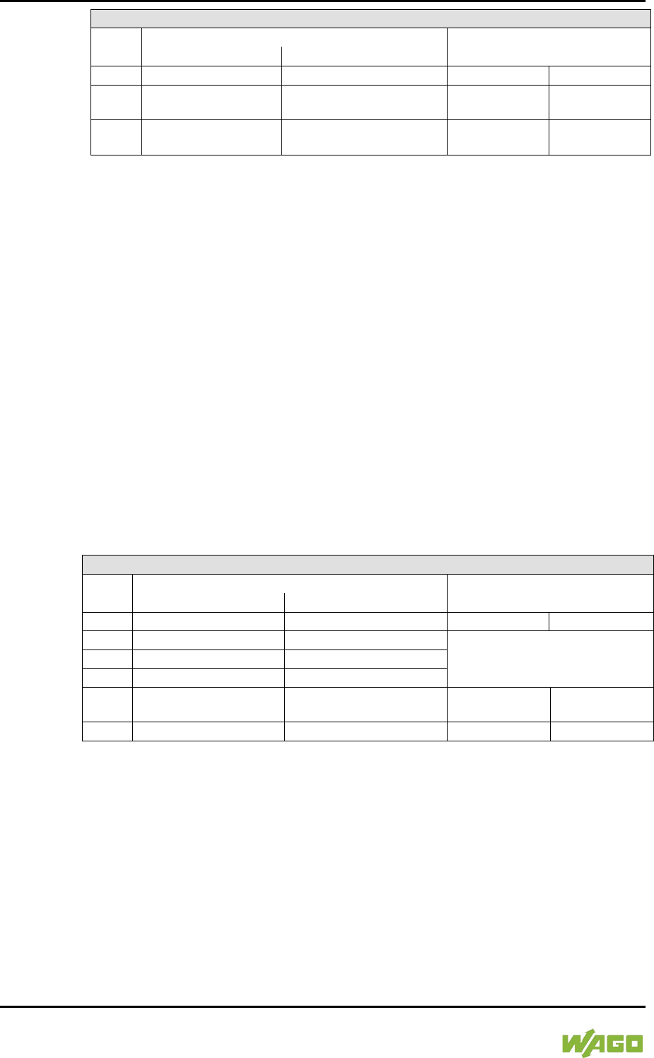
364 Appendix WAGO-I/O-SYSTEM 750
750-8207 PFC200 CS 2ETH RS 3G
Manual
Draft version 1.2.1 from 2017-09-13, valid from FW Version 02.06.20(09)
Output Process Image
Offset
Byte Destination
Description
High Byte
Low Byte
0
C1
C0
Control byte C1
Control byte C0
1 D1 D0
Setpoint position
Setpoint position
(LSB)
2 D3 D2
Setpoint position
(MSB)
Setpoint position
15.1.5.9 Stepper Controller
750-670
The Stepper controller RS422 / 24 V / 20 mA 750-670 provides the fieldbus
coupler 12 bytes input and output process image via 1 logical channel. The data
to be sent and received are stored in up to 7 output bytes (D0 … D6) and 7 input
bytes (D0 … D6), depending on the operating mode.
Output byte D0 and input byte D0 are reserved and have no function assigned.
One I/O module control and status byte (C0, S0) and 3 application control and
status bytes (C1 ... C3, S1 ... S3) provide the control of the data flow.
Switching between the two process images is conducted through bit 5 in the
control byte (C0 (C0.5). Activation of the mailbox is acknowledged by bit 5 of the
status byte S0 (S0.5).
Table 280: Stepper Controller RS 422 / 24 V / 20 mA 750-670
Input Process Image
Offset
Byte Destination
Description
High Byte
Low Byte
0
reserved
S0
reserved
Status byte S0
1
D1
D0
Process data*) / Mailbox**)
2
D3
D2
3
D5
D4
4 S3 D6
Status byte S3
Process data*) /
reserved**)
5
S1
S2
Status byte S1
Status byte S2
*) Cyclic process image (Mailbox disabled)
**)
Mailbox process image (Mailbox activated)
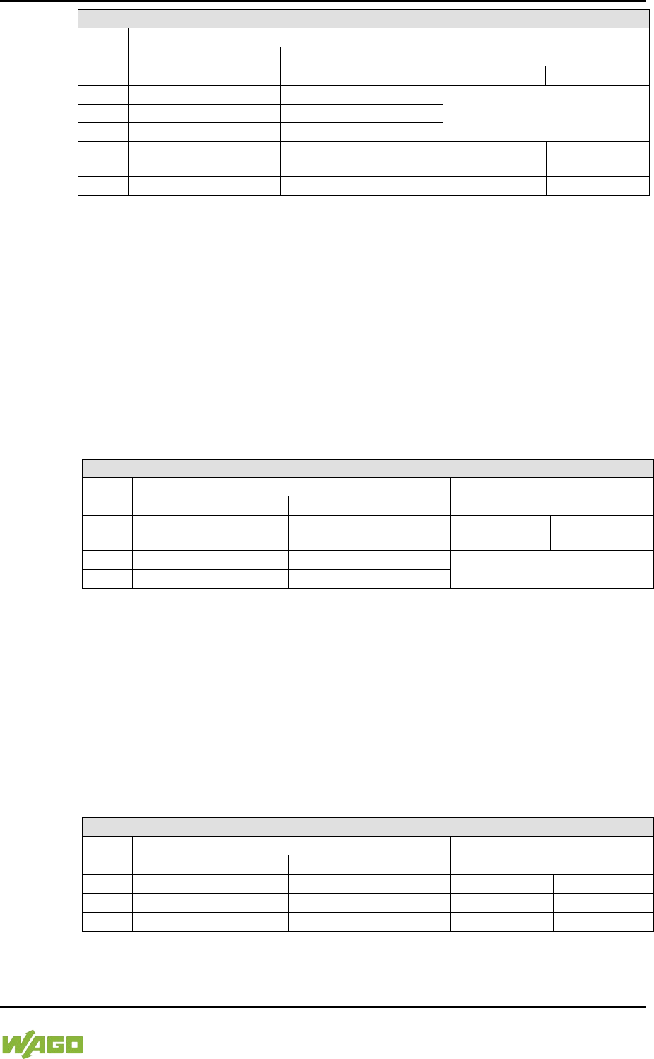
WAGO-I/O-SYSTEM 750 Appendix 365
750-8207 PFC200 CS 2ETH RS 3G
Manual
Draft version 1.2.1 from 2017-09-13, valid from FW Version 02.06.20(09)
Output Process Image
Offset
Byte Destination
Description
High Byte
Low Byte
0
reserved
C0
reserved
Control byte C0
1
D1
D0
Process data*) / Mailbox**)
2
D3
D2
3
D5
D4
4 C3 D6 Control byte C3
Process data*) /
reserved**)
5
C1
C2
Control byte C1
Control byte C2
*) Cyclic process image (Mailbox disabled)
**)
Mailbox process image (Mailbox activated)
15.1.5.10 RTC Module
750-640
The RTC Module has a total of 6 bytes of user data in both the Input and Output
Process Image (4 bytes of module data and 1 byte of control/status and 1 byte ID
for command). The following table illustrates the Input and Output Process
Image, which have 3 words mapped into each image. Word alignment is applied.
Table 281: RTC Module 750-640
Input and Output Process Image
Offset
Byte Destination
Description
High Byte
Low Byte
0 ID C/S Command byte
Control/status
byte
1
D1
D0
Data bytes
2
D3
D2
15.1.5.11 DALI/DSI Master Module
750-641
The DALI/DSI Master module has a total of 6 bytes of user data in both the Input
and Output Process Image (5 bytes of module data and 1 byte of control/status).
The following tables illustrate the Input and Output Process Image, which have 3
words mapped into each image. Word alignment is applied.
Table 282: DALI/DSI Master Module 750-641
Input Process Image
Offset
Byte Destination
Description
High Byte
Low Byte
0
D0
S
DALI Response
Status byte
1
D2
D1
Message 3
DALI Address
2
D4
D3
Message 1
Message 2

366 Appendix WAGO-I/O-SYSTEM 750
750-8207 PFC200 CS 2ETH RS 3G
Manual
Draft version 1.2.1 from 2017-09-13, valid from FW Version 02.06.20(09)
Output Process Image
Offset
Byte Destination
Description
High Byte
Low Byte
0 D0 C
DALI command,
DSI dimming value Control byte
1
D2
D1
Parameter 2
DALI Address
2
D4
D3
Command extension
Parameter 1
15.1.5.12 DALI Multi-Master Module
753-647
The DALI Multi-Master module occupies a total of 24 bytes in the input and
output range of the process image.
The DALI Multi-Master module can be operated in "Easy" mode (default) and
"Full" mode. "Easy" mode is used to transmit simply binary signals for lighting
control. Configuration or programming via DALI master module is unnecessary in
"Easy" mode.
Changes to individual bits of the process image are converted directly into DALI
commands for a pre-configured DALI network. 22 bytes of the 24-byte process
image can be used directly for switching of electronic ballasts (ECG), groups or
scenes in "Easy" mode. Switching commands are transmitted via DALI and group
addresses, where each DALI and each group address is represented by a 2-bit
pair.
The structure of the process data is described in detail in the following tables.
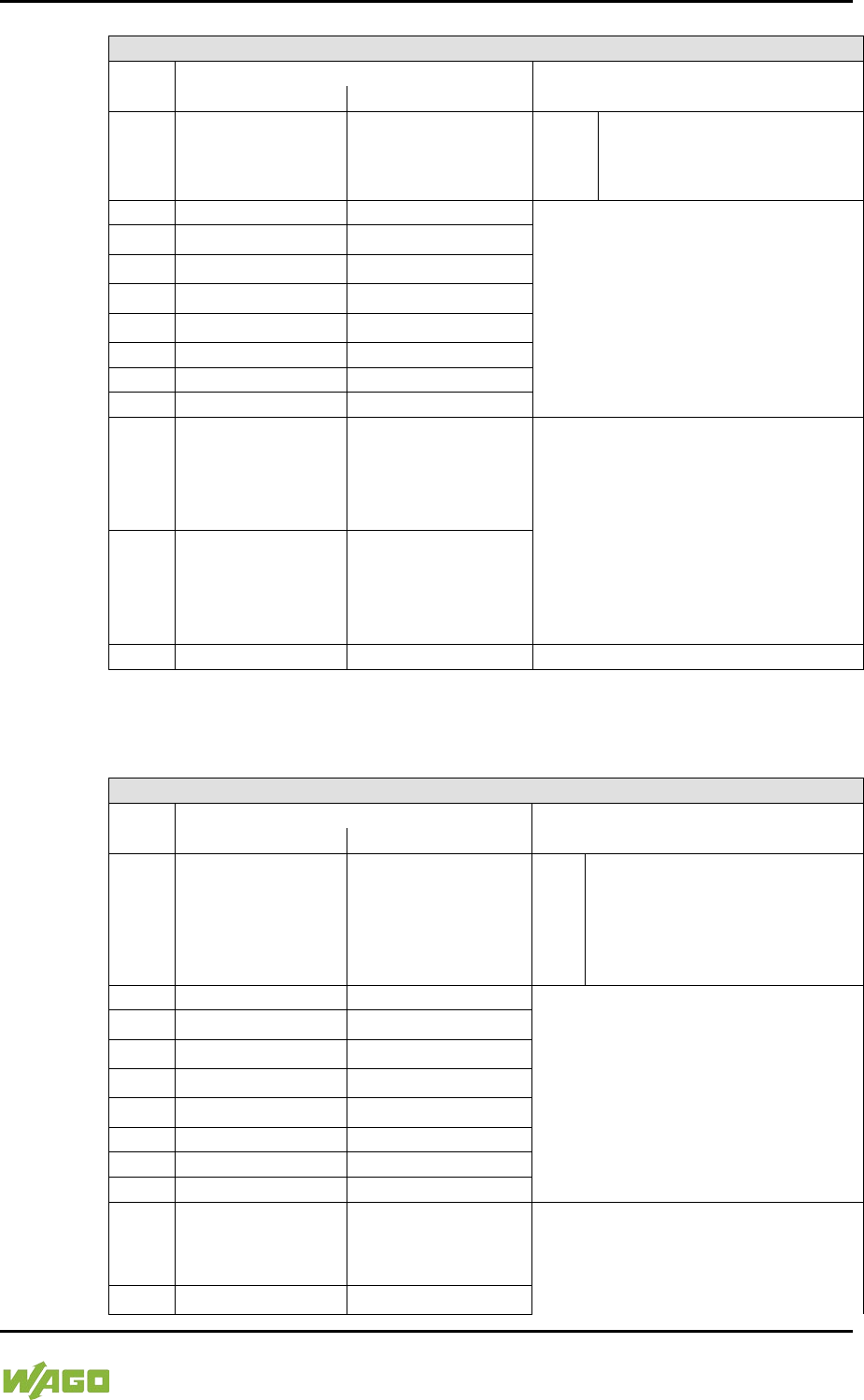
WAGO-I/O-SYSTEM 750 Appendix 367
750-8207 PFC200 CS 2ETH RS 3G
Manual
Draft version 1.2.1 from 2017-09-13, valid from FW Version 02.06.20(09)
Table 283: Overview of Input Process Image in the "Easy" Mode
Input process image
Offset
Byte designation
Note
High byte
Low byte
0 - S
res.
Status, activate broadcast
Bit 0: 1-/2-button mode
Bit 2: Broadcast status ON/OFF
Bit 1,3-7: -
1
DA4…DA7
DA0…DA3
Bitpaar für DALI-Adresse DA0:
2 DA12…DA15 DA8…DA11
Bit 1:
Bit set = ON
3
DA20…DA23
DA16…DA19
Bit not set = OFF
4
DA28…DA31
DA24…DA27
Bit 2:
Bit set = Error
5 DA36…DA39 DA32…DA35
Bit not set = No error
6
DA44…DA47
DA40…DA43
Bit pairs DA1 … DA63 similar to
DA0.
7
DA52…DA55
DA48…DA51
8
DA60…DA63
DA56…DA59
9 GA4…GA7 GA0…GA3
Bit pair for DALI group address
GA0:
Bit 1:
Bit set = ON
Bit not set = OFF
10 GA12…GA15 GA8…GA11
Bit 2:
Bit set = Error
Bit not set = No error
Bit pairs GA1 … GA15 similar to
GA0.
11
-
-
Not in use
DA = DALI address
GA = Group address
Table 284: Overview of the Output Process Image in the "Easy" Mode“
Output process image
Offset
Byte designation
Note
High byte
Low byte
0 - S
res.
Broadcast ON/OFF and activate:
Bit 0: Broadcast ON
Bit 1: Broadcast OFF
Bit 2: Broadcast ON/OFF/dimming
Bit 3: Broadcast short ON/OFF
Bits 4 … 7: reserved
1
DA4…DA7
DA0…DA3
Bit pair for DALI address DA0:
2
DA12…DA15
DA8…DA11
Bit 1:
short: DA switch ON
3
DA20…DA23
DA16…DA19
long: dimming, brighter
4 DA28…DA31 DA24…DA27
Bit 2:
short: DA switch OFF
5 DA36…DA39 DA32…DA35
long: dimming, darker
6
DA44…DA47
DA40…DA43
Bit pairs DA1 … DA63 similar to
DA0.
7
DA52…DA55
DA48…DA51
8
DA60…DA63
DA56…DA59
9 GA4…GA7 GA0…GA3
Bitpaar für DALI-Gruppenadresse GA0:
Bit 1:
short: GA switch ON
long: dimming, brighter
10 GA12…GA15 GA8…GA11
Bit 2:
short: GA switch OFF
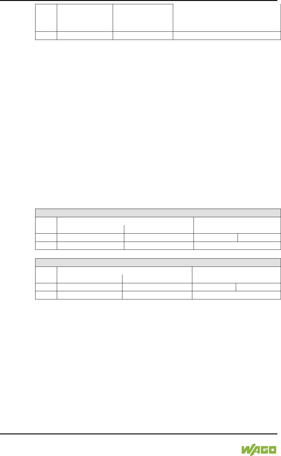
368 Appendix WAGO-I/O-SYSTEM 750
750-8207 PFC200 CS 2ETH RS 3G
Manual
Draft version 1.2.1 from 2017-09-13, valid from FW Version 02.06.20(09)
long: dimming, darker
Bit pairs GA1 … GA15 similar to
GA0.
11
Bit 8…15
Bit 0…7
Switch scene 0…15
DA = DALI address
GA = Group address
15.1.5.13 LON® FTT Module
753-648
The process image of the LON® FTT module consists of a control/status byte and
23 bytes of bidirectional communication data that is processed by the WAGO-I/O-
PRO function block "LON_01.lib". This function block is essential for the function
of the LON® FTT module and provides a user interface on the control side.
15.1.5.14 EnOcean Radio Receiver
750-642
The EnOcean radio receiver has a total of 4 bytes of user data in both the Input
and Output Process Image (3 bytes of module data and 1 byte of control/status).
The following tables illustrate the Input and Output Process Image, which have 2
words mapped into each image. Word alignment is applied.
Table 285: EnOcean Radio Receiver 750-642
Input Process Image
Offset
Byte Destination
Description
High Byte
Low Byte
0
D0
S
Data byte
Status byte
1
D2
D1
Data bytes
Output Process Image
Offset
Byte Destination
Description
High Byte
Low Byte
0
-
C
not used
Control byte
1
-
-
not used
15.1.5.15 MP Bus Master Module
750-643
The MP Bus Master Module has a total of 8 bytes of user data in both the Input
and Output Process Image (6 bytes of module data and 2 bytes of control/status).
The following table illustrates the Input and Output Process Image, which have 4
words mapped into each image. Word alignment is applied.
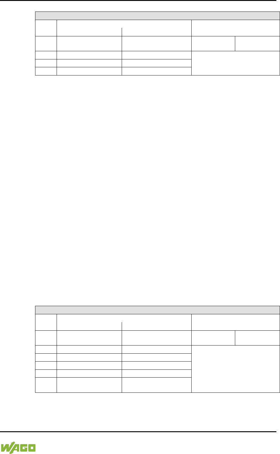
WAGO-I/O-SYSTEM 750 Appendix 369
750-8207 PFC200 CS 2ETH RS 3G
Manual
Draft version 1.2.1 from 2017-09-13, valid from FW Version 02.06.20(09)
Table 286: MP Bus Master Module 750-643
Input and Output Process Image
Offset
Byte Destination
Description
High Byte
Low Byte
0 C1/S1 C0/S0
extended Control/
Status byte
Control/status
byte
1
D1
D0
Data bytes
2
D3
D2
3
D5
D4
15.1.5.16 Bluetooth® RF-Transceiver
750-644
The size of the process image for the Bluetooth® module can be adjusted to 12,
24 or 48 bytes.
It consists of a control byte (input) or status byte (output); an empty byte; an
overlay able mailbox with a size of 6, 12 or 18 bytes (mode 2); and the Bluetooth®
process data with a size of 4 to 46 bytes.
Thus, each Bluetooth® module uses between 12 and 48 bytes in the process
image. The sizes of the input and output process images are always the same.
The first byte contains the control/status byte; the second contains an empty
byte.
Process data attach to this directly when the mailbox is hidden. When the
mailbox is visible, the first 6, 12 or 18 bytes of process data are overlaid by the
mailbox data, depending on their size. Bytes in the area behind the optionally
visible mailbox contain basic process data. The internal structure of the
Bluetooth® process data can be found in the documentation for the Bluetooth®
750-644 RF Transceiver.
The mailbox and the process image sizes are set with the startup tool WAGO-
I/O-CHECK.
Table 287: Bluetooth® RF-Transceiver 750-644
Input and Output Process Image
Offset
Byte Destination
Description
High Byte
Low Byte
0 - C0/S0 not used
Control/status
byte
1
D1
D0
Mailbox (0, 3, 6 or 9 words) and
Process data (2-23 words)
2
D3
D2
3
D5
D4
...
...
...
max.
23
D45 D44

370 Appendix WAGO-I/O-SYSTEM 750
750-8207 PFC200 CS 2ETH RS 3G
Manual
Draft version 1.2.1 from 2017-09-13, valid from FW Version 02.06.20(09)
15.1.5.17 Vibration Velocity/Bearing Condition Monitoring VIB I/O
750-645
The Vibration Velocity/Bearing Condition Monitoring VIB I/O has a total of 12
bytes of user data in both the Input and Output Process Image (8 bytes of
module data and 4 bytes of control/status). The following table illustrates the
Input and Output Process Image, which have 8 words mapped into each image.
Word alignment is applied.
Table 288: Vibration Velocity/Bearing Condition Monitoring VIB I/O 750-645
Input and Output Process Image
Offset
Byte Destination
Description
High Byte
Low Byte
0 - C0/S0 not used
Control/status byte
(log. Channel 1,
Sensor input 1)
1 D1 D0
Data bytes
(log. Channel 1, Sensor input 1)
2 - C1/S1 not used
Control/status byte
(log. Channel 2,
Sensor input 2)
3 D3 D2
Data bytes
(log. Channel 2, Sensor input 2)
4 - C2/S2 not used
Control/status byte
(log. Channel 3,
Sensor input 1)
5 D5 D4
Data bytes
(log. Channel 3, Sensor input 3)
6 - C3/S3 not used
Control/status byte
(log. Channel 4,
Sensor input 2)
7 D7 D6
Data bytes
(log. Channel 4, Sensor input 2)
15.1.5.18 KNX/EIB/TP1 Module
753-646
The KNX/TP1 module appears in router and device mode with a total of 24-byte
user data within the input and output area of the process image, 20 data bytes
and 2 control/status bytes. Even though the additional bytes S1 or C1 are
transferred as data bytes, they are used as extended status and control bytes.
The opcode is used for the read/write command of data and the triggering of
specific functions of the KNX/EIB/TP1 module. Word-alignment is used to assign
12 words in the process image. Access to the process image is not possible in
router mode. Telegrams can only be tunneled.
In device mode, access to the KNX data can only be performed via special
function blocks of the IEC application. Configuration using the ETS engineering
tool software is required for KNX.

WAGO-I/O-SYSTEM 750 Appendix 371
750-8207 PFC200 CS 2ETH RS 3G
Manual
Draft version 1.2.1 from 2017-09-13, valid from FW Version 02.06.20(09)
Table 289: KNX/EIB/TP1 Module 753-646
Input Process Image
Offset
Byte Destination
Description
High Byte
Low Byte
0
-
S0
not used
Status byte
1 S1 OP
extended
Status byte Opcode
2
D1
D0
Data byte 1
Data byte 0
3
D3
D2
Data byte 3
Data byte 2
4
D5
D4
Data byte 5
Data byte 4
5
D7
D6
Data byte 7
Data byte 6
6
D9
D8
Data byte 9
Data byte 8
7
D11
D10
Data byte 11
Data byte 10
8
D13
D12
Data byte 13
Data byte 12
9
D15
D14
Data byte 15
Data byte 14
10
D17
D16
Data byte 17
Data byte 16
11
D19
D18
Data byte 19
Data byte 18
Output Process Image
Offset
Byte Destination
Description
High Byte
Low Byte
0
-
C0
not used
Control byte
1 C1 OP
extended
Control byte
Opcode
2
D1
D0
Data byte 1
Data byte 0
3
D3
D2
Data byte 3
Data byte 2
4
D5
D4
Data byte 5
Data byte 4
5
D7
D6
Data byte 7
Data byte 6
6
D9
D8
Data byte 9
Data byte 8
7
D11
D10
Data byte 11
Data byte 10
8
D13
D12
Data byte 13
Data byte 12
9
D15
D14
Data byte 15
Data byte 14
10
D17
D16
Data byte 17
Data byte 16
11
D19
D18
Data byte 19
Data byte 18
15.1.5.19 AS-interface Master Module
750-655
The length of the process image of the AS-interface master module can be set to
fixed sizes of 12, 20, 24, 32, 40 or 48 bytes.
It consists of a control or status byte, a mailbox with a size of 0, 6, 10, 12 or 18
bytes and the AS-interface process data, which can range from 0 to 32 bytes.
The AS-interface master module has a total of 6 to maximally 24 words data in
both the Input and Output Process Image. Word alignment is applied.
The first Input and output word, which is assigned to an AS-interface master
module, contains the status / control byte and one empty byte.
Subsequently the mailbox data are mapped, when the mailbox is permanently
superimposed (Mode 1).

372 Appendix WAGO-I/O-SYSTEM 750
750-8207 PFC200 CS 2ETH RS 3G
Manual
Draft version 1.2.1 from 2017-09-13, valid from FW Version 02.06.20(09)
In the operating mode with suppressible mailbox (Mode 2), the mailbox and the
cyclical process data are mapped next.
The following words contain the remaining process dat.
The mailbox and the process image sizes are set with the startup tool WAGO-
I/O-CHECK.
Table 290: AS-interface Master Module 750-655
Input and Output Process Image
Offset
Byte Destination
Description
High Byte
Low Byte
0 - C0/S0 not used
Control/status
byte
1
D1
D0
Mailbox (0, 3, 5, 6 or 9 words)/
Process data (0-16 words)
2
D3
D2
3
D5
D4
...
...
...
max.
23
D45 D44

WAGO-I/O-SYSTEM 750 Appendix 373
750-8207 PFC200 CS 2ETH RS 3G
Manual
Draft version 1.2.1 from 2017-09-13, valid from FW Version 02.06.20(09)
15.1.6 System Modules
15.1.6.1 System Modules with Diagnostics
750-610, -611
The modules provide 2 bits of diagnostics in the Input Process Image for
monitoring of the internal power supply.
Table 291: System Modules with Diagnostics 750-610, -611
Input Process Image
Bit 7
Bit 6
Bit 5
Bit 4
Bit 3
Bit 2
Bit 1
Bit 0
Diagnostic
bit S 2
Fuse
Diagnostic bit
S 1
Fuse
15.1.6.2 Binary Space Module
750-622
The Binary Space Modules behave alternatively like 2 channel digital input
modules or output modules and seize depending upon the selected settings 1, 2,
3 or 4 bits per channel. According to this, 2, 4, 6 or 8 bits are occupied then either
in the process input or the process output image.
Table 292: Binary Space Module 750-622 (with Behavior Like 2 Channel Digital Input)
Input and Output Process Image
Bit 7
Bit 6
Bit 5
Bit 4
Bit 3
Bit 2
Bit 1
Bit 0
(Data bit
DI 8)
(Data bit
DI 7)
(Data bit
DI 6)
(Data bit
DI 5)
(Data bit
DI 4)
(Data bit
DI 3)
Data bit
DI 2
Data bit
DI 1

374 Appendix WAGO-I/O-SYSTEM 750
750-8207 PFC200 CS 2ETH RS 3G
Manual
Draft version 1.2.1 from 2017-09-13, valid from FW Version 02.06.20(09)
15.2 CODESYS 2 Libraries
Additional functions for the controller 750-8207are provided using libraries.
15.2.1 General Libraries
This section contains general CODESYS libraries supported by the controller750-
8207.
15.2.1.1 CODESYS System Libraries
All of the functions of the CODESYS system libraries listed below are supported.
Table 293: CODESYS System Libraries
Library
Function
C/IEC 61131
Analyzation.lib
Analysis of boolean expressions
C and IEC 61131
AnalyzationNew.lib
Analysis of boolean expressions
C and IEC 61131
Iecsfc.lib
Provision of implicit variables in the
SFC (sequential function chart)
IEC 61131
NetVarUdp_LIB_V23.lib
Implementation for network
variables
IEC 61131
Standard.LIB
Offers various standard functions
C
SysLibAlarmTrend.lib
Supports alarm and trend tasks
IEC 61131
SysLibCallback.lib
For installing call-back handlers
and event handlers
C
SysLibDir.lib
For accessing directories
C
SysLibDirect.lib
Access to variables using indices
C
SysLibEvent.lib
Handling of events in the system
C
SysLibFileStream.lib
File handling using ANSI-C
functions
C
SysLibGetAddress.lib
Returns addresses and the size of
memory segments
C
SysLibIecTasks.lib
Administration of IEC tasks
C
SysLibMem.lib
Memory administration
C
SysLibPlcCtrl.lib
Control of the PLC from outside
the PLC program
C
SysLibProjectInfo.lib
Reading out of information about
the CODESYS project
C
SysLibSem.lib
Handling of semaphores
C
SysLibSockets.lib
Socket handling
C
SysLibSocketsAsync.lib
Socket handling, asynchronous
C
SysLibStr.lib
String functions
C
SysLibTasks.lib
Administration of tasks
C
SysLibTime.lib
Administration of real-time clock
C
SysLibVisu.lib
Dynamic visualization
C
WAGO-I/O-SYSTEM 750 Appendix 375
750-8207 PFC200 CS 2ETH RS 3G
Manual
Draft version 1.2.1 from 2017-09-13, valid from FW Version 02.06.20(09)
Table 293: CODESYS System Libraries
Library
Function
C/IEC 61131
SysTaskInfo.lib
Evaluation of task information in
the Online mode
IEC 61131
Util.lib
Various logical operations
IEC 61131
Util_no_Real.lib
Various logical operations
IEC 61131
Additional information about the libraries is given in the online Help function for
CODESYS-IDE.
</dg_
15.2.1.2 SysLibCom.lib
The controller 750-8207supports the following function blocks of the
“SysLibCom.lib” library:
- SysComClose
- SysComGetVersion2300
- SysComOpen
- SysComRead
- SysComSetSettings
- SysComSetSettingsEx
- SysComWrite
Observe restrictions on the settings for stop bits!
The setting “1.5 stop bits” is not supported by controller750-8207.
Additional information about this is given in the online Help function for
CODESYS-IDE.
15.2.1.3 SysLibFile.lib
The controller 750-8207supports the following function blocks of the
“SysLibFile.lib” library:
- SysFileClose
- SysFileCopy
- SysFileDelete
- SysFileEOF
- SysFileGetPos
- SysFileGetSize
- SysFileGetTime
- SysFileOpen
- SysFileRead
- SysFileRename
- SysFileSetPos
- SysFileWrite
376 Appendix WAGO-I/O-SYSTEM 750
750-8207 PFC200 CS 2ETH RS 3G
Manual
Draft version 1.2.1 from 2017-09-13, valid from FW Version 02.06.20(09)
Ensure that files are saved!
Files are not reliably saved on the data medium until you call up the
“SysFileClose” function block!
Additional information about this is given in the online Help function for
CODESYS-IDE.
Notes on the parameters of the function blocks
File and directory names distinguish between upper and lower case!
“test.txt”≠ “TEST.TXT”≠ “Test.txt”
The separator for directories is: “/.”
The file system supports:
- Absolute paths, (e.g., “/media/sd/test.txt”)
- Relative paths (e.g., “testpath/test.txt”)
- Macros (e.g., “HOME://”, “CARD://”, “TMP://”)
Table 294: Possible Macros for File Access
Macro
Booting from Internal Memory
Booting from Memory Card
HOME://
“/home/codesys/”
(internal NAND memory)
“/home/codesys/”
(memory card)
CARD://
“/media/sd/”
(nemory card)
“/home/codesys/”
(memory card)
TMP://
“/tmp/codesys/”
(internal RAM memory)
“/tmp/codesys/”
(internal RAM memory)
15.2.1.4 SysLibFileAsync.lib
The controller 750-8207supports the following function blocks of the
“SysLibFileAsync.lib” library:
- SysFileCloseAsync
- SysFileCopyAsync
- SysFileDeleteAsync
- SysFileEOFAsync
- SysFileGetPosAsync
- SysFileGetSizeAsync
- SysFileGetTimeAsync
- SysFileOpenAsync
- SysFileReadAsync
- SysFileRenameAsync
- SysFileSetPosAsync
WAGO-I/O-SYSTEM 750 Appendix 377
750-8207 PFC200 CS 2ETH RS 3G
Manual
Draft version 1.2.1 from 2017-09-13, valid from FW Version 02.06.20(09)
- SysFileWriteAsync
Ensure that files are saved!
Files are not reliably saved to the data medium until you call up the
“SysFileCloseAsync” function block.
Additional information about this is given in the online Help function for
CODESYS-IDE.
Notes on the parameters of the function blocks
File and directory names distinguish between upper and lower case!
“test.txt”≠ “TEST.TXT”≠ “Test.txt”
The separator for directories is: “/.”
The file system supports:
- Absolute paths, (e.g., “/media/sd/test.txt”)
- Relative paths (e.g., “testpath/test.txt”)
- Macros (e.g., “HOME://”, “CARD://”, “TMP://”)
Table 295: Possible Macros for File Access
Macro
Booting from Internal Memory
Booting from Memory Card
HOME://
“/home/codesys/”
(internal NAND memory)
“/home/codesys/”
(memory card)
CARD://
“/media/sd/”
(nemory card)
“/home/codesys/”
(memory card)
TMP://
“/tmp/codesys/”
(internal RAM memory)
“/tmp/codesys/”
(internal RAM memory)
15.2.1.5 SysLibRtc.lib
The controller 750-8207supports the following function blocks of the
“SysLibRtc.lib” library:
- SysRtcGetHourMode
- SysRtcGetTime
- SysRtcSetTime
Additional information about this is given in the online Help function for
CODESYS-IDE.

378 Appendix WAGO-I/O-SYSTEM 750
750-8207 PFC200 CS 2ETH RS 3G
Manual
Draft version 1.2.1 from 2017-09-13, valid from FW Version 02.06.20(09)
15.2.1.6 BusDiag.lib
The controller 750-8207 supports the following function blocks of the
“BusDiag.lib” library:
- DiagGetBusState
- DiagGetState
The document containing a description of this library and the function blocks it
includes is available for download on the Internet at www.wago.com.
The values for the input variables “DEVICENUMBER” of the “DiagGetBusState”
and “DiagGetState” functions are based on the particular device and bus system
and are as follows for the controller “PFC200 CS 2ETH RS 3G” (750-8207):
Table 296: Input Variable “DEVICENUMBER”
Bus System
Value
Internal data bus
0
MODBUS
1
15.2.1.7 mod_com.lib
The controller 750-8207supports the following function blocks of the
“mod_com.lib” library:
- ADD_PI_INFORMATION
- CRC16
- FBUS_ERROR_INFORMATION
- GET_DIGITAL_INPUT_OFFSET
- GET_DIGITAL_OUTPUT_OFFSET
- KBUS_ERROR_INFORMATION
- MOD_COM_VERSION
- PI_INFORMATION
- SET_DIGITAL_INPUT_OFFSET
- SET_DIGITAL_OUTPUT_OFFSET
- SLAVE_ADDRESS
The document containing a description of this library and the function blocks it
includes is available for download on the Internet at www.wago.com.
15.2.1.8 SerComm.lib
The controller 750-8207supports the following function blocks of the
“SerComm.lib” library:
- SERCOMM
- SERCOMM_VERSION
The document containing a description of this library and the function blocks it
includes is available for download on the Internet at www.wago.com.
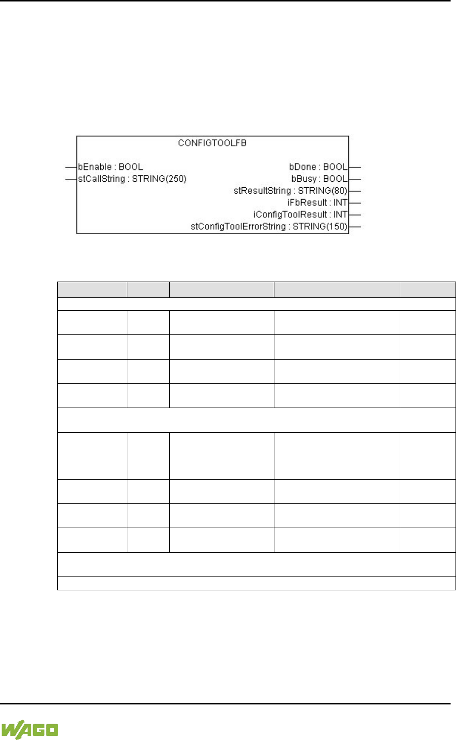
WAGO-I/O-SYSTEM 750 Appendix 379
750-8207 PFC200 CS 2ETH RS 3G
Manual
Draft version 1.2.1 from 2017-09-13, valid from FW Version 02.06.20(09)
15.2.1.9 WagoConfigToolLIB.lib
The following table shows call-ups that allow you to configure and parameterize
the controller from the PLC program or Linux® via the “ConfigToolFB” function
block (see parameter “stCallString”). In addition to WBM and the CBM, this is
another variant to configure the controller for operational requirements.
The configuration directory for this under Linux® is: /etc/config-tools/
Figure 123: Graphical Representation of the “ConfigToolFB” Function Block
Table 297: Description of the Configuration Scripts for “Information”
Parameters
Status
Call-Up
Output/Input
Effective
Controller Details: Identifies various information about the controller
Product
Description
read
get_coupler_details
product-description
Product description Immediately
Order Number read
get_coupler_details
order-number
Item number of the controller Immediately
Firmware
Revision
read
get_coupler_details
firmware-revision
Firmware version of the
controller
Immediately
Licence
Information
read
get_coupler_details
license-information
CODESYS license details Immediately
Network Details X1: Identifies the parameters currently used for the ETHERNET interface
X1/X2 in “switched” mode or for the ETHERNET interface X1 in “separated” mode
State read get_actual_eth_config
X1 state
Status of the interface.
Possible return values:
- enabled
- disabled
Immediately
Mac Address read
get_actual_eth_config
X1 mac-address Display of the MAC address Immediately
IP Address read
get_actual_eth_config
X1 ip-address
Display of current IP address Immediately
Subnet Mask read
get_actual_eth_config
X1 subnet-mask
Display of the current subnet
mask
Immediately
Network Details X2: Identifies the parameters currently used for the ETHERNET interface X2
in “separated” mode
See “Network Details X1”. When calling these up, replace “X1” with “X2” (in “separated” mode only).
</dg_

380 Appendix WAGO-I/O-SYSTEM 750
750-8207 PFC200 CS 2ETH RS 3G
Manual
Draft version 1.2.1 from 2017-09-13, valid from FW Version 02.06.20(09)
Table 298: Description of the Configuration Scripts for “CODESYS”
Parameters
Status
Call
Output/Input
Effecti
ve
Information
CODESYS
Webserver
Version
read
get_coupler_details
codesys-Webserver-
version
Version of the CODESYS
Webserver
Immedia
tely
Project Details
Date read
get_rts_info
project date
Display of the project information
specified in CODESYS (Menu >
Project > Project Information)
Immedia
tely
Title read
get_rts_info
project title
Immedia
tely
Version read
get_rts_info
project version
Immedia
tely
Author read
get_rts_info
project author
Immedia
tely
Description read
get_rts_info
project description
Immedia
tely
CODESYS State
State read
get_rts_info
state
Display of the CODESYS status
(RUN or STOP)
Immedia
tely
Home Directory (Boot Project Location)
Home Directory
(Boot Project
Location)
read get_runtime_config
homedir-on-sdcard
Storage logation for the home
directory.
Possible return values:
- enabled: The home directory
is on the SD card.
- disabled: The home directory
is on the boot medium.
After
restart
write
config_runtime
homedir-on-
sdcard=<Wert>
Storage logation for the home
directory.
Possible entries for the value are:
- enabled: Put the home
directory on the SD card.
- disabled: The home directory
is on the boot medium.

WAGO-I/O-SYSTEM 750 Appendix 381
750-8207 PFC200 CS 2ETH RS 3G
Manual
Draft version 1.2.1 from 2017-09-13, valid from FW Version 02.06.20(09)
Table 299: Description of the Configuration Scripts for “Networking - Host/Domain Name”
Parameters
Status
Call
Output/Input
Effecti
ve
Host Name
Host Name
read get_coupler_details
hostname
Display of the host name.
The return value is blank when
/etc/hostname is empty.
For details see the parameter
“Actual Hostname.”
Immedia
tely
write
change_hostname
hostname=<String>
Changing the host name.
Input a host name for <String>.
Immedia
tely
Actual
Hostname read get_coupler_details
actual-hostname
The actual host name (if
/etc/hostname is empty, a unique
host name is generated from the
MAC address)
Immedia
tely
Domain Name
Domain name
read
get_coupler_details
domain-name
Display of domain name Immedia
tely
write
change_hostname
dnsdomain=<String>
Change the domain name. Enter
the domain name for <String>.
Table 300: Description of the Configuration Scripts for “Networking - TCP/IP”
Parameters
Status
Call
Output/Input
Effecti
ve
IP Address X1: Determines the IP parameters of the ETHERNET interfaces X1/X2 in
“switched” mode and the ETHERNET interface X1 in “separated” mode
Type of IP
address
configuration
read get_eth_config
X1 config-type
Path via which the interface
receives its IP address
Possible return values are:
- static (set statically)
- dhcp (per DHC)
- bootp (per BootP)
Immedia
tely
write
config_interfaces
interface=X1
config-type=<Value>
state=enabled
Enable process, via which the
interface receives its IP address
Possible entries for <Value> are:
- static (set statically)
- dhcp (per DHC)
- bootp (per BootP)
IP address
read
get_eth_config
X1 ip-address
Address set for using a static IP
address (static IP).
Immedia
tely
write
config_interfaces
interface=X1
ip-address=<Value>
Change IP address for static IP
<Value> must have an IP address
with the format
“Number.Number.Number.Numbe
r.”
Subnet Mask
read
get_eth_config
X1 subnet-mask
Subnet mask set for using a static
IP address (static IP)
Immedia
tely
write
config_interfaces
interface=X1
subnet-mask=<Value>
Change subnet mask for static IP
addresses. <Value> must have
an IP address with the format
“Number.Number.Number.Numbe
r.”
IP Address X2: Determines the parameters currently used for the ETHERNET interface X2 in
“separated” mode
See “IP Address X1.” When calling these up, replace X1 with X2 (only permissible in “separated”
mode).

382 Appendix WAGO-I/O-SYSTEM 750
750-8207 PFC200 CS 2ETH RS 3G
Manual
Draft version 1.2.1 from 2017-09-13, valid from FW Version 02.06.20(09)
Table 300: Description of the Configuration Scripts for “Networking - TCP/IP”
Parameters
Status
Call
Output/Input
Effecti
ve
Default Gateway 1
Default
Gateway
read get_default_gateway_
config number=1 state
Current status of the default
gateway 1.
Possible return values:
- enabled
- disabled
Immedia
tely
write
config_default_gateway
number=1
state=<stateval>
Possible entries for <Value>:
- enabled
- disabled
Default
Gateway
read
get_default_gateway_
config number=1 value
Current IP address of the default
gateway 1
Immedia
tely
write config_default_gateway
number=1 value=<gw>
Enter the IP address of the
default gateway 1 here.
<gw> is an IP address with the
format “Number. Number.
Number. Number.”
Default
Gateway
read get_default_gateway_
config number=1 metric
Current metric (cost factor) of the
default gateway 1
The default value is “20.” Immedia
tely
write config_default_gateway
number=1 metric=<n>
Enter the metric of the default
gateway 1 here.
<n> is a number between “0” and
“4.294.967.295.”
Default Gateway 2
See “Default Gateway 1.” When calling the gateway number, replace 1 with 2.
DNS Server 1
DNS Server 1
read get_dns_server 1
DNS server address with the
consecutive number 1
Immedia
tely
write/
change
edit_dns_server
dns-server-nr=1
change=change
dns-server-
name=<Value>
Set the address of the DNS
server with 1 as the consecutive
number.
<Value> is an IP address with the
format
“Number.Number.Number.Numbe
r.”
write/
delete
edit_dns_server
dns-server-nr=1
delete=delete
Delete the DNS server with the
consecutive number 1.
DNS Server 2 … n
See “DNS Server 1.” When calling, adjust the server number (2 … n).
Add DNS Server
Add DNS server write
edit_dns_server
add=add dns-server-
name=<Value>
Add additional DNS addresses
here.
<Value> is an IP address with the
format
“Number.Number.Number.Numbe
r.”
Immedia
tely

WAGO-I/O-SYSTEM 750 Appendix 383
750-8207 PFC200 CS 2ETH RS 3G
Manual
Draft version 1.2.1 from 2017-09-13, valid from FW Version 02.06.20(09)
Table 301: Description of the Configuration Scripts for “Networking - ETHERNET”
Parameters
Status
Call-Up
Output/Input
Effective
Switch Configuration
Interface Mode
read get_dsa_mode
Query the switch
configuration:
Possible return values:
- 0 = „switched“ mode
- 1 = „separated“ mode
Immediately
write set_dsa_mode -v
<value>
Set the switch configuration:
Possible entries for <value>:
- 0 = „switched“ mode
- 1 = „separated“ mode
Interface X1
Port State
read get_eth_config
X1 state
Query the port state:
Possible return values:
- enabled
- disabled
Immediately
write
config_ethernet port=X1
state=enabled
Activate port: enabled
config_ethernet port=X1
state=disabled Deactivate port: disabled
Autonegotiation
read get_eth_config
X1 autoneg
Query the status of the
autonegotiation function:
Possible return values:
- on
- off
Immediately
write
config_ethernet port=X1
autoneg=on
Activate the autonegotiation
function: on
config_ethernet port=X1
autoneg=off
speed=<value>
duplex=<value>
Deactivate the autonegotiation
function: off
Note: You must also indicate
the speed and duplex value
when you deactivate the
autonegotiation function.
Possible entries for speed:
- 10M
- 100M
Possible entries for duplex:
- half
- full
Speed and
Duplex Settings
read
get_eth_config
X1 speed
Display of ETHERNET speed
Immediately
read
get_eth_config
X1 duplex
Display of the Duplex mode
write
config_ethernet port=X1
autoneg=off
speed=<value>
duplex=<value>
Change the ETHERNET
speed and the Duplex mode.
Possible entries for speed:
- 10M
- 100M
Possible entries for duplex:
- half
- full
Interface X2
See “Interface X1”. When calling these up, replace “X1” with “X2”.
</dg_

384 Appendix WAGO-I/O-SYSTEM 750
750-8207 PFC200 CS 2ETH RS 3G
Manual
Draft version 1.2.1 from 2017-09-13, valid from FW Version 02.06.20(09)
Table 302: Description of the Configuration Scripts for “NTP”
Parameters
Status
Call
Output/Input
Effecti
ve
Configuration Data
State
read get_ntp_config
state
Query the status of the NTP
server
Possible return values are:
- enabled
- disabled
Immedia
tely
write config_sntp
state=<Value>
Possible entries for <Value>:
- enabled
- disabled
Port
read
get_ntp_config
port
Port number of the NTP server
Immedia
tely
write
config_sntp
port=<Value>
Enter the port number for
<Value>.
Time Server
read get_ntp_config
time-server-<N>
Query the IP address of the time
server: N = 1 … 4 for querying
one of 4 time servers.
Immedia
tely
write
config_sntp
time-server-
<N>=<Value>
Enter the IP address of 4 time
servers
<N> can be a value from 1 to 4.
<Value> is an IP address with the
format “Number. Number.
Number. Number.”
Update Time
(seconds)
read get_ntp_config
update-time
Query the time in seconds
between two requests to the time
server.
Immedia
tely
write
config_sntp
update-time=<Value>
Specify the time-server's query
cycle (in s) for <Value>.

WAGO-I/O-SYSTEM 750 Appendix 385
750-8207 PFC200 CS 2ETH RS 3G
Manual
Draft version 1.2.1 from 2017-09-13, valid from FW Version 02.06.20(09)
Table 303: Description of the Configuration Scripts for “Clock”
Parameters
Status
Call-Up
Output/Input
Effective
Clock
Time and Date
Date on device,
local
read
get_clock_data
date-local
Local time and date
Immediately
write
config_clock
type=local
date=<Datum>
Change date. The format for
<date> is: DD.MM.YYYY
Time on device,
UTC
read
get_clock_data
time-utc Time/UTC
Immediately
write config_clock
type=utc time=<Time>
Change time, based on UTC
time. The format for <time> is:
hh:mm:ss xx
Time on device,
local
read
get_clock_data
time-local
Time/local time
Immediately
write config_clock
type=local time=<Time>
Change time, based on local
time. The format for <time> is:
hh:mm:ss xx
12-Hour-
Format
read get_clock_data
display-mode
Presentation format either as
12 or 24-hour format:
Possible return values:
- 12-hour-format
- 24-hour-format
Immediately
write
config_clock _
display_mode
display-mode=<value>
Set the presentation format
for the time.
Possible entries for <Value>:
- 12-hour-format
- 24-hour-format
Time Zone
TZ-String
read get_clock_data
tz-string
Currently set time zone –
original TZ string as stored in
the operating system.
Immediately
write config_timezone
tz-string=<String>
Change TZ string directly.
Example of <String>:
CET-1CEST,
M3.5.0/2,M10.5.0/3
Table 304: Description of the Configuration Scripts for "Administration"
Parameters
Status
Call
Output/Input
Effecti
ve
Administration
Configuration of Serial Interface
Configuration of
serial interface
read get_coupler_details
RS232-owner
User of the serial interface
Possible return values are:
- Linux
- None
immedia
tely
write config_RS232
owner=<value>
User of the serial interface
Possible entries for <value> are:
- Linux
- None

386 Appendix WAGO-I/O-SYSTEM 750
750-8207 PFC200 CS 2ETH RS 3G
Manual
Draft version 1.2.1 from 2017-09-13, valid from FW Version 02.06.20(09)
Table 304: Description of the Configuration Scripts for "Administration"
Parameters
Status
Call
Output/Input
Effecti
ve
Configuration of Service Interface
Configuration of
Service
Interface
read get_service_interface_
config mode
User of the serial interface.
Possible return values are:
- service (WAGO-I/O-CHECK,
WAGO-I/O-PRO,
e!COCKPIT)
- linux (Linux® console)
- free (unused, free for
application)
immedia
tely
write config_service_interface
_config mode=<value>
User of the serial interface.
Possible entries for <value>:
- service
- linux
- free
Reboot Controller
- write start_reboot Restart the controller.
immedia
tely
</dg_
Table 305: Description of Configuration Scripts for “Package Server”
Parameters
Status
Call-Up
Output/Input
Valid
Firmware Update
Medium for
active partition read get_filesystem_data
active-partition-medium
Specifies the medium for the
active partition
(memory card, internal flash).
Right
away
Create
firmware
backup
write
firmware_backup
package-
settings=<Value1>
package-
codesys=<Value2>
package-
system=<Value3>
device-
medium=<Value4>
auto-update=<Value5>
Generates a backup of the
selected packet on the specified
medium.
Parameter:
<Value1> = 1, if “Settings” packet
is to be selected.
<Value2> = 1, if the “CODESYS
Project” packet is to be selected.
<Value3> = 1, if the “System”
packet is to be selected.
<Value4> = Target medium for
saving the backup.
(memory card, internal flash)
<Value5> = 1, if Auto Update is
to be activated.
Parameters, which are not to be
set (1) can either be set to 0 or
omitted completely.
Right
away
</dg_

WAGO-I/O-SYSTEM 750 Appendix 387
750-8207 PFC200 CS 2ETH RS 3G
Manual
Draft version 1.2.1 from 2017-09-13, valid from FW Version 02.06.20(09)
Table 306: Description of Configuration Scripts for “Ports and Services” – “Network Services
Parameters
Status
Call-Up
Output/Input
Valid
Network Services
Telnet
Telnet Port
read get_port_state
telnet
Read the status of the Telnet
server.
Possible return values:
- enabled
- disabled
Right
away
write
config_port
port=telnet
state=<Value>
Possible entries for <Value>:
- enabled
- disabled
FTP
FTP Port
read config_ssl
ftp-status
Read the status of the FTP
server.
Possible return values:
- enabled
- disabled
Right
away
write config_port
port=ftp state=<Value>
Possible entries for <Value>:
- enabled
- disabled
FTPS
FTPS Port
read config_ssl ftps-status
Read the status of the FTPS port.
Possible return values:
- enabled
- disabled
Right
away
write config_port port=ftps
state=<Value>
Activate/Deactivate FTPS.
Possible entries for <Value>:
- enabled
- disabled
HTTP
HTTP Port
read config_ssl http-status
Read the status of the HTTP port.
Possible return values:
- enabled
- disabled
Right
away
write config_port port=http
state=<Value>
Activate/Deactivate HTTP.
Possible entries for <Value>:
- enabled
- disabled
HTTPS
HTTPS Port
read config_ssl https-status
Read the status of the HTTPS
port.
Possible return values:
- enabled
- disabled
Right
away
write config_port port=https
state=<Value>
Activate/Deactivate HTTPS.
Possible entries for <Value>:
- enabled
- disabled

388 Appendix WAGO-I/O-SYSTEM 750
750-8207 PFC200 CS 2ETH RS 3G
Manual
Draft version 1.2.1 from 2017-09-13, valid from FW Version 02.06.20(09)
Table 307: Description of Configuration Scripts for “Ports and Services” – “PLC Runtime Services”
Parameters
Status
Call
Output/Input
Effecti
ve
General Settings
PLC runtime
version
read get_runtime_config
running-version
Version of the enabled PLC
runtime
Possible return values:
- 0 = no runtime enabled
- 2 = CODESYS 2 enabled
- 3 =
e!
RUNTIME enabled
Immedia
tely
write config_runtime runtime-
version=<value>
Setting and, if necessary,
stopping of the previous runtime
version and starting of required
version
Possible entries for <value>:
- 0 = do not enable runtime
- 2 = enable CODESYS2
- 3 = enable e!RUNTIME
Boot project
location
read get_runtime_config
boot-project
Memory location for a boot
project of the runtime application
Possible return values:
- HOME:// (saving on internal
memory)
- CARD:// (saving on the
memory card)
Immedia
tely
write config_runtime boot-
project=<value>
Possible entries for <value>:
- HOME:// (saving on internal
memory)
- CARD:// (saving on the
memory card)
Default web
page
read get_runtime_config
default-webpage
Calling web page when only
entering the IP address in the
web browser
Possible return values:
- WBM (web based
management)
- Webvisu (web visualization)
Immedia
tely
write config_runtime default-
webpage=<value>
Possible entries for <value>:
- WBM (web based
management)
- Webvisu (web visualization)
Change
authentication
password
write
config_linux_user
user=admin new-
password=<value>
confirm-
password=<value>
Change the PLC runtime access
password
Immedia
tely

WAGO-I/O-SYSTEM 750 Appendix 389
750-8207 PFC200 CS 2ETH RS 3G
Manual
Draft version 1.2.1 from 2017-09-13, valid from FW Version 02.06.20(09)
Table 307: Description of Configuration Scripts for “Ports and Services” – “PLC Runtime Services”
Parameters
Status
Call
Output/Input
Effecti
ve
CODESYS 2 Settings
CODESYS2
Webserver
State
read
get_runtime_config cfg-
version=2 Webserver-
state
Read status of the runtime-
specific Webserver
Possible return values:
- enabled
- disabled
Immedia
tely
write
config_runtime cfg-
version=2 Webserver-
state=<value>
Enable/disable runtime-specific
Webserver
Possible entries for <value>:
- enabled
- disabled
CODESYS2
Port
Authentication
read get_runtime_config cfg-
version=2 authentication
Read status of the port
authentication for communication
between the CODESYS 2 PC
software and the controller
Possible return values:
- enabled
- disabled
Immedia
tely
write
config_runtime cfg-
version=2
authentication=<value>
Possible entries for <value>:
- enabled
- disabled
CODESYS2
Service State
read get_runtime_config
service-state
Read status of the port for
communication between the
CODESYS 2 PC software and
the controller
Possible return values:
- enabled
- disabled
Immedia
tely
write config_runtime service-
state=<value>
Possible entries for <value>:
- enabled
- disabled
CODESYS2
Communication
Port
read get_runtime_config
comm-port
Read value of set network port
for communication between PC
and controller
Default value is 2455
Immedia
tely
write config_runtime comm-
port=<value>
Change port number
Enter the TCP/IP port number for
<value>.

390 Appendix WAGO-I/O-SYSTEM 750
750-8207 PFC200 CS 2ETH RS 3G
Manual
Draft version 1.2.1 from 2017-09-13, valid from FW Version 02.06.20(09)
Table 307: Description of Configuration Scripts for “Ports and Services” – “PLC Runtime Services”
Parameters
Status
Call
Output/Input
Effecti
ve
e!Runtime Settings
e!RUNTIME
Webserver
State
read
get_runtime_config cfg-
version=3 Webserver-
state
Read status of the runtime-
specific Webserver
Possible return values
- enabled
- disabled
Immedia
tely
write
config_runtime cfg-
version=3 Webserver-
state=<value>
Enable/disable runtime-specific
Webserver
Possible entries for <value>:
- enabled
- disabled
e!RUNTIME
Port
Authentication
read get_runtime_config cfg-
version=3 authentication
Read status of the port
authentication for communication
between the e!COCKPIT PC
software and the controller
Possible return values:
- enabled
- disabled
Immedia
tely
write
config_runtime cfg-
version=3
authentication= <value>
Possible entries for <value>:
- enabled
- disabled
</dg_

WAGO-I/O-SYSTEM 750 Appendix 391
750-8207 PFC200 CS 2ETH RS 3G
Manual
Draft version 1.2.1 from 2017-09-13, valid from FW Version 02.06.20(09)
Table 308: Description of Configuration Scripts for “Ports and Services” – “SSH/TFTP”
Parameters
Status
Call-Up
Output/Input
Valid
SSH
SSH Server
SSH
read get_ssh_config state
Read the status of the SSH port.
Possible return values:
- enabled
- disabled
Right
away
read get_ssh_config root-
access-state
Indicates whether logon as root is
permitted.
Possible return values:
- enabled
- disabled
read get_ssh_config
password-request-state
Indicates whether authentication
by password (instead of PKI key
files) is permitted.
Possible return values:
- enabled
- disabled
read
get_ssh_config port-
number
Specifies the SSH port
write config_ssh
state=<Value>
Activate/Deactivate SSH service.
Possible entries for <Value>:
- enabled
- disabled
write
config_ssh port-
number=<Value>
Set the SSH port
write config_ssh root-access-
state-value=<Value>
Permit/Prohibit logon as root.
Possible entries for <Value>:
- enabled
- disabled
write
config_ssh password-
request-state-
value=<Value>
Permit/Prohibit authentication by
password.
Possible entries for <Value>:
- enabled
- disabled
TFTP
TFTP Server
TFTP
read get_tftp_config state
Read the status of the TFTP port.
Possible return values:
- enabled
- disabled
Right
away
read
get_tftp_config
download-dir
Read the TFTP main directory.
write config_tftp
state=<Value>
Activate/Deactivate TFTP port.
Possible entries for <Value>:
- enabled
- disabled
write
config_tftp download-
dir=<Value>
Set the TFTP main directory.
<

392 Appendix WAGO-I/O-SYSTEM 750
750-8207 PFC200 CS 2ETH RS 3G
Manual
Draft version 1.2.1 from 2017-09-13, valid from FW Version 02.06.20(09)
Table 309: Description of Configuration Scripts for “SNMP”
Parameters
Status
Call-Up
Output/Input
Valid
General SNMP information parameters
Name of device
read
get_snmp_data
device-name
Specifies the SNMP parameter
“sysName”.
Right
away
write config_snmp
device-name=<Value>
Change the SNMP parameter
“sysName”
(<Value> = string).
*
After
restart
Description
read
get_snmp_data
description
Specifies the SNMP parameter
“sysDescr”.
Right
away
write config_snmp
description=<Value>
Change the SNMP parameter
“sysDescr”
(<Value> = string).
*
After
restart
Physical
location
read
get_snmp_data
physical-location
Specifies the SNMP
“sysLocation” parameter.
Right
away
write
config_snmp
physical-
location=<Value>
Change the SNMP parameter
“sysLocation”
(<Value> = string).
*
After
restart
Contact
read
get_snmp_data
contact
Specifies the SNMP “sysContact”
parameter.
Right
away
write config_snmp
contact=<Value>
Change the SNMP parameter
“sysContact”
(<Value> = string).
After
restart
* When entering values, the blank characters must be filled by either “+” or “%20”. If this is not
done, the input is not recognized as a coherent string.
SNMP Manager configuration for v1 and v2c
Protocol status read get_snmp_data
v1-v2c-state
Outputs the status of the SNMP
protocol for v1/v2c as a string.
Possible return values:
- enabled
- disabled
Right
away
Local
Community
Name
read get_snmp_data
v1-v2c-community-name
Specifies the community name
set for v1/v2c/
Right
away
Protocol
Status/Commu
nity Name
write
config_snmp
v1-v2c-state=<Value1>
v1-v2c-community-
name=<Value2>
Activates/deactivates the v1/v2c
protocol (<Value1> = enabled or
disabled) and assigns a
community name. (<Value2> =
string without spaces, min. 1,
max. 32 characters).
Note:
No community name is required
for deactivation.
Activation is only possible by
entering a community name. A
community name can only be
saved when the protocol is
activated.
After
restart

WAGO-I/O-SYSTEM 750 Appendix 393
750-8207 PFC200 CS 2ETH RS 3G
Manual
Draft version 1.2.1 from 2017-09-13, valid from FW Version 02.06.20(09)
Table 309: Description of Configuration Scripts for “SNMP”
Parameters
Status
Call-Up
Output/Input
Valid
SNMP Trap Receiver Configuration for v1 and v2c
Any number of trap receivers can be configured. A trap receiver that has been set up is always
active; the data set must be completely deleted to deactivate it.
IP address of a
trap receiver read
get_snmp_data
v1-v2c-trap-receiver-
address <Nummer>
Specifies the IP address of the
trap receiver that the controller is
to send the v1 or v2 traps to.
The <number> parameter
enables consecutive reading of
related data from the individually
configured trap receiver for a
short period of time (without
interim changing of the data).
This is a consecutive number that
is not connected to the data. If
the number is not included, the
data of the first receiver are read.
Right
away
Community
Name read
get_snmp_data
v1-v2c-trap-receiver-
community-name
<Nummer>
Specifies the community name
that the SNMP agent of the
controller sends in the Trap
Header.
Parameter <number> see section
“IP Address of a Trap Receiver”.
Right
away
Trap version read
get_snmp_data
v1-v2c-trap-receiver-
version <Nummer>
Specifies the SNMP version (“v1”
or “v2c”) via which the SNMP
agent sends the traps to the
associated trap receiver address.
Parameter <number> see section
“IP Address of a Trap Receiver”.
Right
away
Creating/
deleting a trap
receiver
write
config_snmp
v1-v2c-trap-receiver-
edit=<Value1>
v1-v2c-trap-receiver-
address=<Value2>
v1-v2c-trap-receiver-
community-
name=<Value3>
v1-v2c-trap-receiver-
version=<Value4>
Create a new trap receiver
(value1=add) or delete an
already configured trap receiver
(value1=delete).
Other parameters:
<Value2> = IP address
(number.number.number.number
) that the controller is to send the
traps to.
<Value3>: Community string
(string), which the controller
enters in the trap header.
<Value4>: SNMP version, via
which the traps are sent (v1 or
v2c).
Note:
All parameters must also be
entered when deleting a trap
receiver, as this is the only
means to uniquely identify the
data set.
After
restart

394 Appendix WAGO-I/O-SYSTEM 750
750-8207 PFC200 CS 2ETH RS 3G
Manual
Draft version 1.2.1 from 2017-09-13, valid from FW Version 02.06.20(09)
Table 309: Description of Configuration Scripts for “SNMP”
Parameters
Status
Call-Up
Output/Input
Valid
Configuration of SNMP v3
Any number of SNMP v3 users can be created. A user that has been set up is always active; the
complete data set must be deleted to deactivate a user.
Authentication
Name read
get_snmp_data
v3-auth-name
<Nummer>
Specifies the user name for the
v3 user.
The <number> parameter
enables consecutive reading of
the related data from the
individually configured trap
receiver for a short period of time
(without interim changing of the
data). This is a consecutive
number that is not connected to
the data. If the number is not
included, the data of the first user
are read.
Right
away
Authentication
encryption type read get_snmp_data
v3-auth-type <Number>
Specifies the type of encryption
that the v3 user uses (none,
MD5, or SHA).
Parameter <number> see
“Authentication Name”.
Right
away
Authentication
key read get_snmp_data
v3-auth-key <Nummer>
Specifies the key string for
authentication.
Parameter <number> see
“Authentication Name”.
Right
away
Privacy
encryption type read get_snmp_data
v3-privacy <number>
Specifies the type of privacy
encryption for the v3 user (none,
DES, or AES).
Parameter <number> see
“Authentication Name”.
Right
away
Privacy key read
get_snmp_data
v3-privacy-key
<number>
Specifies the key string for
privacy. If nothing is entered, the
SNMP agent uses the
“Authentication Key”.
Parameter <number> see
“Authentication Name”.
Right
away
Trap receiver
address read
get_snmp_data
v3-notification-receiver
<number>
IP address of an SNMP manager
that the agent traps for this v3
user are sent to. If nothing is
entered here, no traps are sent
for this user.
Parameter <number> see
“Authentication Name”.
Right
away

WAGO-I/O-SYSTEM 750 Appendix 395
750-8207 PFC200 CS 2ETH RS 3G
Manual
Draft version 1.2.1 from 2017-09-13, valid from FW Version 02.06.20(09)
Table 309: Description of Configuration Scripts for “SNMP”
Parameters
Status
Call-Up
Output/Input
Valid
Add new v3-
User write
config_snmp
v3-edit=add
v3-auth-name=<Value1>
v3-auth-type=<Value2>
v3-auth-key=<Value3>
v3-privacy=<Value4>
v3-privacy-
key=<Value5>
v3-notification-
receiver=<Value6>
Creating a new v3 user.
v3-auth-name: User name, string
without spaces, maximum of 32
characters. This must be a new,
unique user name.
Parameters:
User name (<Value1> = string)
Encryption method. (<Value2> =
none, MD5 or SHA).
Key string for authentication,
(<Value3> = String with at least
eight and a maximum of 32
characters)
Privacy encryption method
(<Value4> = none, DES or AES).
Privacy key string (<Value5> =
String with at least eight and a
maximum of 32 characters), can
also be blank; in this case the
authentication key will be used.
The IP address of a trap receiver
is transmitted as the notification
receiver (<Value6> =
number.number.number.number)
. This parameter is not required if
no v3 traps are to be sent.
After
restart
Delete v3 user write
config_snmp
v3-edit=delete
v3-auth-name=<Value>
Deleting a v3 user that has been
set up.
Because the doubled allocation
of the same user name is
prevented when creating a user,
the name is sufficient to uniquely
identify a data set (<Value> =
string).
After
restart
15.2.1.10 WagoLibCpuUsage.lib
The controller 750-8207supports the following function blocks of the
“WagoLibCpuUsage.lib” library:
- CPU_Usage
The document containing the description of the library and the function block it
includes is available for download on the Internet at www.wago.com.
15.2.1.11 WagoLibDiagnosticIDs.lib
The controller 750-8207supports the following function blocks of the
“WagoLibDiagnosticIDs.lib” library:
- DIAGNOSTIC_SEND_ID
- DIAGNOSTIC_SET_TEXT_FOR_ID

396 Appendix WAGO-I/O-SYSTEM 750
750-8207 PFC200 CS 2ETH RS 3G
Manual
Draft version 1.2.1 from 2017-09-13, valid from FW Version 02.06.20(09)
The document containing the description of the library and the function block it
includes is available for download on the Internet at www.wago.com.
15.2.1.12 WagoLibLed.lib
The controller 750-8207supports the following function blocks of the
“WagoLibLed.lib” library:
- LED_SET_STATIC
- LED_SET_BLINK
- LED_SET_FLASH
- LED_SET_ERROR
- LED_RESET_ERROR
- LED_RESET_ALL_ERRORS
- LED_GET_STATE
- LED_GET_STATE_ASYNC
The document containing a description of this library and the function blocks it
includes is available for download on the Internet at www.wago.com.
15.2.1.13 WagoLibNetSnmp.lib
The controller 750-8207supports the following function blocks of the
“WagoLibNetSnmp.lib” library:
- snmpGetValueCustomOID_INT32
- snmpGetValueCustomOID_STRING
- snmpGetValueCustomOID_UINT32
- snmpRegisterCustomOID_INT32
- snmpRegisterCustomOID_STRING
- snmpRegisterCustomOID_UINT32
- snmpSetValueCustomOID_INT32
- snmpSetValueCustomOID_STRING
- snmpSetValueCustomOID_UINT32
The document containing the description of the library and the function block it
includes is available for download on the Internet at www.wago.com.
15.2.1.14 WagoLibNetSnmpManager.lib
The controller 750-8207supports the following function blocks of the
“WagoLibNetSnmpManager.lib” libraries:
- SNMPM_DINT_TO_TLV
- SNMPM_UDINT_TO_TLV
- SNMPM_STRING_TO_TLV
- SNMPM_TLV_TO_DINT
- SNMPM_TLV_TO_UDINT
- SNMPM_TLV_TO_STRING
- SNMPM_GET
- SNMPM_GET_V3

WAGO-I/O-SYSTEM 750 Appendix 397
750-8207 PFC200 CS 2ETH RS 3G
Manual
Draft version 1.2.1 from 2017-09-13, valid from FW Version 02.06.20(09)
- SNMPM_SET
- SNMPM_SET_V3
The document containing a description of this library and the function blocks it
includes is available for download on the Internet at www.wago.com.
15.2.1.15 WagoLibSSL.lib
The controller 750-8207supports the following function blocks of the
“WagoLibSSL.lib” library:
- SSL_CTX
- SSL_CTX_load_verify_locations
- SSL_CTX_sess_set_cache_size
- SSL_CTX_set_client_CA_list
- SSL_CTX_set_method
- SSL_CTX_use_certificate_file
- SSL_CTX_use_PrivateKey_file
- SSL_free
- SSL_get_error
- SSL_Hndshk_Accept
- SSL_Hndshk_Connect
- SSL_load_client_CA_file
- SSL_read
- SSL_shutdown
- SSL_write
The document containing a description of this library and the function blocks it
includes is available for download on the Internet at www.wago.com.
15.2.1.16 WagoLibTerminalDiag.lib
The controller 750-8207supports the following function blocks of the
“WagoLibTerminalDiag.lib” library:
- GET_TERMINALDIAG
The document containing a description of this library and the function blocks it
includes is available for download on the Internet at www.wago.com.

398 List of Figures WAGO-I/O-SYSTEM 750
750-8207 PFC200 CS 2ETH RS 3G
Manual
Draft version 1.2.1 from 2017-09-13, valid from FW Version 02.06.20(09)
List of Figures
Figure 1: View of device .....................................................................................27
Figure 2: Marking Area for Serial Numbers ........................................................29
Figure 3: Data Contacts .....................................................................................30
Figure 4: Power Jumper Contacts ......................................................................31
Figure 5: CAGE CLAMP® connections ...............................................................32
Figure 6: Service Interface (Closed and Open Flap) ...........................................33
Figure 7: Network Connections – X1, X2 ............................................................34
Figure 8: RS-232/RS-485 – X3 Communication Connection ..............................35
Figure 9: Termination with DTE-DCE Connection (1:1) ......................................36
Figure 10: Termination with DTE-DTE Connection (Cross-Over) .......................36
Figure 11: RS-485 Bus Termination ...................................................................37
Figure 12: Mobile Radio Antenna Connection ....................................................38
Figure 13: Power Supply Indicating Elements ....................................................39
Figure 14: Indicating elements for fieldbus/system .............................................40
Figure 15: Indicating Elements, Memory Card Slot .............................................41
Figure 16: Indicating Elements, RJ-45 Jacks ......................................................42
Figure 17: Mobile Radio Network Status Indicators ............................................43
Figure 18: Mode Selector Switch ........................................................................44
Figure 19: Reset Button .....................................................................................45
Figure 20: Slot for SD Memory Card ..................................................................46
Figure 21: SIM Card Slot ....................................................................................47
Figure 22: Schematic diagram ............................................................................48
Figure 23: Spacing .............................................................................................75
Figure 24: Release Tab of Controller ..................................................................77
Figure 25: Insert I/O Module (Example) ..............................................................78
Figure 26: Snap the I/O Module into Place (Example) ........................................78
Figure 27: Connecting a Conductor to a CAGE CLAMP® ...................................79
Figure 28: Fuse Protection of the Electronic Circuit Power Supply .....................80
Figure 29: Power Supply Concept ......................................................................81
Figure 30: “Open DHCP”, Example Figure .........................................................85
Figure 31: CBM Starting Screen .........................................................................86
Figure 32: CBM – Selecting “Networking” ...........................................................87
Figure 33: CBM – Selecting “TCP/IP” .................................................................87
Figure 34: CBM – Selecting “IP address” ...........................................................87
Figure 35: CBM – Selecting the IP Address .......................................................88
Figure 36: CBM – Entering a New IP Address ....................................................88
Figure 37: “WAGO Ethernet Settings” – Starting Screen (Example) ...................89
Figure 38: “WAGO Ethernet Settings” – “Network” Tab ......................................90
Figure 39: Example of a Function Test ...............................................................92
Figure 40: Entering Authentication .....................................................................99
Figure 41: Password Reminder ........................................................................ 100
Figure 42: WBM Browser Window (Example) ................................................... 102
Figure 43: WBM Status Information (Example)................................................. 102
Figure 44: CBM main menu (example) ............................................................. 164
Figure 45: “WAGO ETHERNET Settings” – Start Screen ................................. 215
Figure 46: “WAGO ETHERNET Settings” – Communication Link ..................... 216
Figure 47: “WAGO ETHERNET Settings” – Identification Tab (Example) ......... 217

WAGO-I/O-SYSTEM 750 List of Figures 399
750-8207 PFC200 CS 2ETH RS 3G
Manual
Draft version 1.2.1 from 2017-09-13, valid from FW Version 02.06.20(09)
Figure 48: “WAGO ETHERNET Settings” – Network Tab ................................. 218
Figure 49: “WAGO ETHERNET Settings” – Protocol Tab ................................. 220
Figure 50: “WAGO ETHERNET Settings” – Status Tab .................................... 221
Figure 51: Target System Settings (1) .............................................................. 223
Figure 52: Target System Settings (2) .............................................................. 223
Figure 53: Creating a New Function Block ....................................................... 224
Figure 54: Programming Interface with the PLC_PRG Program Module .......... 224
Figure 55: “Resources” Tab.............................................................................. 225
Figure 56: Control Configuration – Edit ............................................................ 226
Figure 57: “Start WAGO-I/O-CHECK and Scan” Button ................................... 226
Figure 58: WAGO-I/O-CHECK – Starting Screen ............................................. 227
Figure 59: I/O Configurator Empty .................................................................... 228
Figure 60: “Add I/O Modules” Button ................................................................ 228
Figure 61: “Module Selection” Window ............................................................. 229
Figure 62: I/O Configurator with Defined I/O Modules ...................................... 229
Figure 63: Variable declaration ......................................................................... 230
Figure 64: Control Configuration: I/O Modules with Their Associated Addresses
................................................................................................................ 230
Figure 65: Program Function Block .................................................................. 231
Figure 66: Input Assistant for Selecting Variables ............................................ 231
Figure 67: Example of an Allocation ................................................................. 232
Figure 68: Creating a Communication Link – Step 1 ........................................ 233
Figure 69: Creating a Communication Link – Step 2 ........................................ 234
Figure 70: Creating a Communication Link – Step 3 ........................................ 234
Figure 71: Task Configuration .......................................................................... 236
Figure 72: Changing Task Names 1 ................................................................. 237
Figure 73: Call-up to Add to the Program Module ............................................. 238
Figure 74: Cyclic Task ...................................................................................... 239
Figure 75: Freewheeling Task .......................................................................... 240
Figure 76: Debugging (Case 1) ........................................................................ 241
Figure 77: Debugging (Case 2) ........................................................................ 241
Figure 78: Debugging (Case 3) ........................................................................ 242
Figure 79: Debugging (Case 4) ........................................................................ 242
Figure 80: Debugging (Case 5) ........................................................................ 243
Figure 81: Debugging (Case 6) ........................................................................ 243
Figure 82: Debugging (Case 7) ........................................................................ 244
Figure 83: CODESYS – System Events ........................................................... 245
Figure 84: CODESYS Program Provokes Division by “0” ................................. 247
Figure 85: CODESYS – Creating and Activating an Event Handler .................. 247
Figure 86: CODESYS – New Module has been Generated .............................. 248
Figure 87: CODESYS – Enter the Event in a Global Variable ........................... 248
Figure 88: CODESYS – Variable Contents Prior to Division by “0” ................... 249
Figure 89: CODESYS – Variable Contents After Division by “0” and Call-up of the
Event Handler ......................................................................................... 249
Figure 90: Process Image ................................................................................ 250
Figure 91: Flag Area ........................................................................................ 251
Figure 92: Internal Data Bus Synchronization 01 .............................................. 256
Figure 93: I/O Module Synchronization 02 ........................................................ 257
Figure 94: I/O Module Synchronization 03 ........................................................ 258
Figure 95: Internal Data Bus Synchronization 04 .............................................. 259

400 List of Figures WAGO-I/O-SYSTEM 750
750-8207 PFC200 CS 2ETH RS 3G
Manual
Draft version 1.2.1 from 2017-09-13, valid from FW Version 02.06.20(09)
Figure 96: Internal Data Bus Settings ............................................................... 260
Figure 97: Program Memory (Example) ........................................................... 263
Figure 98: Data Memory and Function Block Limitation (Example)................... 264
Figure 99: Remanent Main Memory (Example) ................................................ 265
Figure 100: Flag and Retain Memory (Example) .............................................. 265
Figure 101: General Target System Settings .................................................... 266
Figure 102: Selecting the Visualization Technique in the Target System Settings
................................................................................................................ 267
Figure 103: Creating the PLC_VISU Starting Visualization ............................... 268
Figure 104: Remanent Main Memory ............................................................... 276
Figure 105: CODESYS PLC Configuration - MODBUS Settings ...................... 278
Figure 106: MODBUS Process Image .............................................................. 284
Figure 107: Flag Area....................................................................................... 285
Figure 108: State Diagram, STANDARD_WATCHDOG Operation Mode ......... 295
Figure 109: State Diagram, ALTERNATIVE_WATCHDOG Operation Mode .... 296
Figure 110: State Diagram, Switchover Operation Mode .................................. 297
Figure 111: MODBUS Address Overview ......................................................... 306
Figure 112: State Diagram, ADVANCED_WATCHDOG Operation Mode......... 309
Figure 113: State Diagram, SIMPLE_WATCHDOG Operation Mode ............... 310
Figure 114: State Diagram, Switching Operation Modes .................................. 310
Figure 115: Power Supply Indicating Elements ................................................ 318
Figure 116: Mobile Radio Network Status Indicators ........................................ 319
Figure 117: Indicating elements for fieldbus/system ......................................... 320
Figure 118: Flashing Sequence Process Diagram ............................................ 328
Figure 119: Inserting the Memory Card ............................................................ 336
Figure 120: Inserting the SIM Card ................................................................... 338
Figure 121: Release Tab of Controller .............................................................. 342
Figure 122: Removing the I/O Module (Example) ............................................. 343
Figure 123: Graphical Representation of the “ConfigToolFB” Function Block ... 379

WAGO-I/O-SYSTEM 750 List of Tables 401
750-8207 PFC200 CS 2ETH RS 3G
Manual
Draft version 1.2.1 from 2017-09-13, valid from FW Version 02.06.20(09)
List of Tables
Table 1: Variants ................................................................................................15
Table 2: Number Notation ..................................................................................18
Table 3: Font Conventions .................................................................................18
Table 4: Legend for Figure “View” ......................................................................27
Table 5: Legend for Figure “Power Jumper Contacts” ........................................31
Table 6: Legend for figure “CAGE CLAMP® connections” ..................................32
Table 7: Service Interface ..................................................................................33
Table 8: Legend for Figure “Network Connections – X1, X2” ..............................34
Table 9: Legend for Figure “RS-232/RS-485 – X3 Communication Connection” 35
Table 10: Function of RS-232 Signals for DTE/DCE ..........................................36
Table 11: Legend for Figure “Power Supply Indicating Elements” ......................39
Table 12: Legend for Figure “Fieldbus/System Indicating Elements” ..................40
Table 13: Legend for Figure “Indicating Elements, Memory Card Slot” ...............41
Table 14: Legend for Figure “Indicating Elements, RJ-45 Jacks” ........................42
Table 15: Legend for the “Mobile Radio Network Status Indicators” Figure ........43
Table 16: Mode Selector Switch .........................................................................44
Table 17: Mode Selector Switch .........................................................................44
Table 18: Legend for Figure “SIM Card Slot” ......................................................47
Table 19: Technical Data − Device Data ............................................................49
Table 20: Technical Data – System Data ...........................................................49
Table 21: Technical Data – Power Supply ..........................................................49
Table 22: Technical Data – Clock .......................................................................50
Table 23: Technical Data – Programming ..........................................................50
Table 24: Technical Data – Internal Data Bus ....................................................50
Table 25: Technical Data – ETHERNET.............................................................51
Table 26: Technical Data – Serial Interface ........................................................51
Table 27: Technical Data – Mobile Radio Modem ..............................................51
Table 28: Technical Data – Field Wiring .............................................................51
Table 29: Technical Data – Power Jumper Contacts ..........................................52
Table 30: Technical Data – Data Contacts .........................................................52
Table 31: Technical Data – Climatic Environmental Conditions ..........................52
Table 32: WBM Users ........................................................................................57
Table 33: Linux® Users .......................................................................................57
Table 34: List of Parameters Transmitted via DHCP ..........................................63
Table 35: WAGO DIN Rails ................................................................................75
Table 36: Filter Modules for 24 V Supply ............................................................81
Table 37: Default IP Addresses for ETHERNET Interfaces ................................84
Table 38: Network Mask 255.255.255.0 .............................................................84
Table 39: User Settings in the Default State ..................................................... 100
Table 40: Access Rights for WBM Pages ......................................................... 100
Table 41: WBM “Status Information” Page – “Controller Details” Group ........... 105
Table 42: WBM “Status Information Page – “Network Details (Xn)” Group(s) ... 105
Table 43: WBM “General PLC Runtime Configuration” Page – “General PLC
Runtime Configuration” Group ................................................................ 106
Table 44: WBM “PLC Runtime Information” Page – “PLC Runtime” Group ...... 108
Table 45: WBM “PLC Runtime Information” Page – “Project Details” Group .... 108
Table 46: WBM “PLC Runtime Information” Page – “Task n” Group(s) ............ 109

402 List of Tables WAGO-I/O-SYSTEM 750
750-8207 PFC200 CS 2ETH RS 3G
Manual
Draft version 1.2.1 from 2017-09-13, valid from FW Version 02.06.20(09)
Table 47: WBM “PLC WebVisu” Page – “Web Server Configuration” Group .... 110
Table 48: WBM “Configuration of Host and Domain Name” Page – “Hostname”
Group ...................................................................................................... 111
Table 49: WBM “Configuration of Host and Domain Name” Page – “Domain
Name” Group .......................................................................................... 111
Table 50: WBM “TCP/IP Configuration” Page – “IP Configuration (Xn)” Group(s)
................................................................................................................ 112
Table 51: WBM “TCP/IP Configuration” Page – “Default Gateway n” Group .... 113
Table 52: WBM “TCP/IP Configuration” Page – “DNS Server” Group ............... 114
Table 53: WBM “Ethernet Configuration” Page – “Switch Configuration” Group
................................................................................................................ 115
Table 54: WBM “Ethernet Configuration” Page – “Interface Xn” Groups ........... 116
Table 55: WBM “General Firewall Configuration” Page – “Global Firewall
Parameters” Group ................................................................................. 117
Table 56: WBM “General Firewall Configuration” Page – “Firewall Parameter
Interface Xn” Group ................................................................................. 118
Table 57: WBM “Configuration of MAC Address Filter” Page – “Global MAC
Address Filter State” Group ..................................................................... 119
Table 58: WBM “Configuration of MAC Address Filter” Page – “MAC Address
Filter State Xn” Group ............................................................................. 120
Table 59: WBM “Configuration of MAC Address Filter” Page – “MAC Address
Filter Whitelist” Group ............................................................................. 120
Table 60: WBM “Configuration of User Filter” Page – “User Filter” Group ....... 121
Table 61: WBM “Configuration of User Filter” Page – “User Filter n” Group ..... 121
Table 62: WBM “Configuration of User Filter” Page – “Add New User Filter”
Group ...................................................................................................... 122
Table 63: WBM “Configuration of Time and Date” Page – “Date on Device” Group
................................................................................................................ 123
Table 64: WBM “Configuration of Time and Date” Page – “Time on Device”
Group ...................................................................................................... 123
Table 65: WBM “Configuration of Time and Date” Page – “Time Zone” Group . 124
Table 66: WBM “Configuration of Time and Date” Page – “TZ String” Group ... 125
Table 67: WBM “Configuration of the users for the Web-based Management”
Page – “Change Password for Selected User” Group ............................. 126
Table 68: WBM “Create Bootable Image” page – “Create bootable image from
active partition” Group ............................................................................. 127
Table 69: WBM “Configuration of Serial Interface RS232” Page – “Assign Owner
of Serial Interface” Group ........................................................................ 129
Table 70: WBM “Configuration of Serial Interface RS-232” page – “Assign Owner
of Service Interface” Group ..................................................................... 130
Table 71: “Firmware-Backup” WBM Page ........................................................ 132
Table 72: “Firmware Restore” WBM Page ........................................................ 134
Table 73: WBM “Mass Storage” Page – “<Device Name>” Group .................... 137
Table 74: WBM “Mass Storage” Page – “<Device Name>” Group .................... 137
Table 75: WBM “Software Uploads” Page – “Upload New Software” Group ..... 138
Table 76: WBM “Software Uploads” Page – “Activate New Software” Group ... 138
Table 77: WBM “Configuration of Network Services” Page – “Telnet” Group .... 139
Table 78: WBM “Configuration of Network Services” Page – “FTP” Group ....... 139
Table 79: WBM “Configuration of Network Services” Page – “FTPS” Group .... 139
Table 80: WBM “Configuration of Network Services” Page – “HTTP” Group .... 139

WAGO-I/O-SYSTEM 750 List of Tables 403
750-8207 PFC200 CS 2ETH RS 3G
Manual
Draft version 1.2.1 from 2017-09-13, valid from FW Version 02.06.20(09)
Table 81: WBM “Configuration of Network Services” Page – “HTTPS” Group .. 140
Table 82: WBM “Configuration of Network Services” Page – “I/O-CHECK” Group
................................................................................................................ 140
Table 83: WBM “Configuration of NTP Client” Page – “NTP Client Configuration”
Group ...................................................................................................... 141
Table 84: WBM “Configuration of PLC Runtime Services” Page – “General
Configuration” Group ............................................................................... 142
Table 85: WBM “Configuration of CODESYS Services” Page – “CODESYS 2
Web Server” Group ................................................................................. 142
Table 86: WBM “Configuration of CODESYS Services” Page – “e!RUNTIME Web
Server” Group ......................................................................................... 142
Table 87: WBM “SSH Server Settings” Page – “SSH Server” Group ................ 144
Table 88: WBM “TFTP Server” Page – “TFTP Server” Group .......................... 145
Table 89: WBM “DHCP Configuration” – “DHCP Configuration Xn” Group ....... 146
Table 90: WBM “Configuration of DNS Service” Page – “DNS Service” Group 147
Table 91: WBM “MODBUS Services Configuration” Page – “MODBUS TCP”
Group ...................................................................................................... 148
Table 92: WBM “MODBUS Configuration Services” Page – “MODBUS UDP”
Group ...................................................................................................... 148
Table 93: WBM “Configuration of General SNMP Parameters” Page – “General
SNMP Configuration” Group ................................................................... 149
Table 94: WBM “Configuration of SNMP v1/v2c Parameters” Page – “SNMP
v1/v2c Manager Configuration” Group..................................................... 150
Table 95: WBM “Configuration of SNMP v1/v2c Parameters” Page – “Actually
Configured Trap Receivers” Group ......................................................... 150
Table 96: WBM “Configuration of SNMP v1/v2c Parameters” Page – “Trap
Receiver n” Group(s) ............................................................................... 151
Table 97: WBM “Configuration of SNMP v1/v2c Parameters” Page – “Add New
Trap Receiver” Group ............................................................................. 151
Table 98: WBM “Configuration of SNMP v3” Page – “Actually Configured v3
Users” Group .......................................................................................... 152
Table 99: WBM “Configuration of SNMP v3 Users” Page – “v3 User n” Group(s)
................................................................................................................ 152
Table 100: WBM “Configuration of SNMP v3 Users” Page – “Add New v3 User”
Group ...................................................................................................... 153
Table 101: WBM “Diagnostic Information” Page ............................................... 154
Table 102: WBM “Configuration of internal 3G Modem” Page – “SIM
Authentication” Group ............................................................................. 155
Table 103: WBM “Configuration of internal 3G Modem” Page – “Mobile Network
Configuration” Group ............................................................................... 156
Table 104: WBM “Configuration of internal 3G Modem” Page – “Provider List”
Group ...................................................................................................... 157
Table 105: WBM “Configuration of internal 3G Modem” Page – “Network
Package Service” Group ......................................................................... 157
Table 106: WBM “Configuration of internal 3G Modem” Page – “Upload and
activate new Modem Software” Group .................................................... 158
Table 107: WBM “Configuration of OpenVPN and IPsec” Page – “OpenVPN”
Group ...................................................................................................... 159
Table 108: WBM “Configuration of OpenVPN and IPsec” Page – “IPsec” Group
................................................................................................................ 159

404 List of Tables WAGO-I/O-SYSTEM 750
750-8207 PFC200 CS 2ETH RS 3G
Manual
Draft version 1.2.1 from 2017-09-13, valid from FW Version 02.06.20(09)
Table 109: WBM “Configuration of OpenVPN and IPsec” Page – “Certificate
Upload” Group ........................................................................................ 160
Table 110: WBM “Configuration of OpenVPN and IPsec” Page – “Certificate List”
Group ...................................................................................................... 160
Table 111: WBM “Configuration of OpenVPN and IPsec” Page – “Private Key
List” Group .............................................................................................. 160
Table 112: “Security Settings” WBM Page – “TLS Configuration” Group .......... 161
Table 113: CBM Menu Structure ...................................................................... 164
Table 114: “Information” Menu ......................................................................... 167
Table 115: “Information” > “Controller Details” Submenu.................................. 167
Table 116: “Information” > “Network Details” Submenu .................................... 168
Table 117: “PLC Runtime” Menu ...................................................................... 169
Table 118: “PLC Runtime” > “Information” Submenu ........................................ 169
Table 119: “PLC Runtime” > “Information” > “Runtime Version” Submenu ....... 170
Table 120: “PLC Runtime” > “Information” > “Webserver Version” Submenu ... 170
Table 121: “PLC Runtime” > “Information” > “State” Submenu ......................... 170
Table 122: “PLC Runtime” > “Information” > “Number of Tasks” Submenu ...... 171
Table 123: “PLC Runtime” > “Information” > “Project Details” Submenu........... 171
Table 124: “PLC Runtime” > “Information” > “Tasks” Submenu ........................ 171
Table 125: “PLC Runtime” > “Information” > “Tasks” > “Task n” Submenu ....... 172
Table 126: “PLC Runtime” > “General Configuration” Submenu ....................... 172
Table 127: “PLC Runtime” > “General Configuration” > “PLC Runtime Version”
Submenu ................................................................................................ 173
Table 128: “PLC Runtime” > “General Configuration” > “Home Dir On SD Card”
Submenu ................................................................................................ 173
Table 129: “PLC Runtime” > “WebVisu” Submenu ........................................... 174
Table 130: “Networking” Menu ......................................................................... 175
Table 131: “Networking” > “Host/Domain Name” Submenu .............................. 175
Table 132: “Networking” > “Hostname” Submenu ............................................ 176
Table 133: “Networking” > “Host/Domain Name” > “Domain Name” Submenu . 176
Table 134: “Networking” > “TCP/IP” Submenu ................................................. 176
Table 135: “Networking” > “IP Address” Submenu ........................................... 177
Table 136: “Networking” > “TCP/IP” > “IP Address” Submenu > “Xn” ............... 177
Table 137: “Networking” > “TCP/IP” > “Default Gateway” Submenu ................. 178
Table 138: “Networking” > “TCP/IP” > “Default Gateway” > “Default Gateway n”
Submenu ................................................................................................ 178
Table 139: “Networking” > “TCP/IP” > “DNS Server” Submenu ........................ 179
Table 140: “Networking” > “Ethernet” Submenu ............................................... 179
Table 141: “Networking” > “Ethernet” > “Switch Configuration” Submenu......... 180
Table 142: “Networking” > “Ethernet” > “Ethernet Ports” Submenu .................. 180
Table 143: “Networking” > “Ethernet” > “Ethernet Ports” > “Interface Xn”
Submenu ................................................................................................ 181
Table 144: “Firewall” Menu ............................................................................... 182
Table 145: “Firewall” > “General Configuration” Submenu ................................ 183
Table 146: “Firewall” > “General Configuration” > “Interface xxx” Submenu ..... 184
Table 147: “Firewall” > “MAC Address Filter” Submenu ................................... 186
Table 148: “Firewall” > “MAC Address Filter” > “MAC address filter whitelist”
Submenu ................................................................................................ 187
Table 149: “Firewall” > “MAC Address Filter” > “MAC address filter whitelist” >
“Add new / No (n)” Submenu ................................................................... 187

WAGO-I/O-SYSTEM 750 List of Tables 405
750-8207 PFC200 CS 2ETH RS 3G
Manual
Draft version 1.2.1 from 2017-09-13, valid from FW Version 02.06.20(09)
Table 150: “Firewall” > “User Filter” Submenu .................................................. 188
Table 151: “Firewall” > “User Filter” > “Add New / No (n)” Submenu ................ 189
Table 152: “Clock” Menu .................................................................................. 190
Table 153: “Administration” Menu..................................................................... 191
Table 154: “Administration” > “Create Image” Submenu................................... 192
Table 155: “Administration” > “Users” Submenu ............................................... 192
Table 156: “Package Server” Menu .................................................................. 193
Table 157: “Package Server” > “Firmware Backup” Menu ................................ 193
Table 158: “Package Server” > “Firmware Backup” > “Auto Update Feature”
Menu ....................................................................................................... 194
Table 159: “Package Server” > “Firmware Backup” > “Auto Update Feature”
Menu ....................................................................................................... 194
Table 160: “Package Server” > “Firmware Restore” Menu ............................... 195
Table 161: “Package Server” > “Firmware Restore” > “Select Package” Menu. 195
Table 162: “Package Server” > “System Partition” Submenu ........................... 196
Table 163: “Mass Storage” Menu ..................................................................... 197
Table 164: “Mass Storage” > “SD Card” Menu ................................................. 197
Table 165: “Ports and Services” Menu ............................................................. 199
Table 166: “Ports and Services” > “Telnet” Submenu ....................................... 200
Table 167: “Ports and Services” > “FTP” Submenu .......................................... 200
Table 168: “Ports and Services” > “FTPS” Submenu ........................................ 201
Table 169: “Ports and Services” > “HTTP” Submenu ....................................... 201
Table 170: “Ports and Services” > “HTTPS” Submenu ..................................... 202
Table 171: “Ports and Services” > “NTP” Submenu .......................................... 202
Table 172: “Ports and Services” > “SSH” Submenu ......................................... 203
Table 173: “Ports and Services” > “TFTP” Submenu ........................................ 203
Table 174: “Ports and Services” > “DHCPD” Submenu .................................... 204
Table 175: “Ports and Services” > “DHCPD” > “Xn” Submenu ......................... 204
Table 176: “Ports and Services” > “DNS” Submenu ......................................... 205
Table 177: “Ports and Services” > “IOCHECK PORT” Submenu ...................... 206
Table 178: “Ports and Services” > “Modbus TCP” Submenu ............................ 206
Table 179: “Ports and Services” > “Modbus UDP” Submenu ............................ 207
Table 180: “Ports and Services” > “PLC Runtime Services” Submenu ............. 207
Table 181: “Ports and Services” > “PLC Runtime Services” > “CODESYS 2”
Submenu ................................................................................................ 208
Table 182: “Ports and Services” > “PLC Runtime Services” > “e!RUNTIME”
Submenu ................................................................................................ 209
Table 183: “Ports and Services” > “Firewall Status” Submenu.......................... 210
Table 184: “SNMP” Menu ................................................................................. 211
Table 185: “SNMP” > “General SNMP Configuration” Submenu ...................... 211
Table 186: “SNMP” > “SNMP v1/v2c Manager Configuration” Submenu .......... 212
Table 187: “SNMP” > “SNMP v1/v2c Trap Receiver Configuration” Submenu .. 212
Table 188: “SNMP” > “SNMP v3 Configuration” Submenu ............................... 213
Table 189: “SNMP” > “(Secure )SNMP firewalling” Submenu ........................... 214
Table 190: Syntax of Logical Addresses........................................................... 235
Table 191: Events ............................................................................................ 246
Table 192: Access to the Process Images of the Input and Output Data – Internal
Data Bus ................................................................................................. 252
Table 193: Access to the Process Images of the Input and Output Data –
MODBUS ................................................................................................ 253

406 List of Tables WAGO-I/O-SYSTEM 750
750-8207 PFC200 CS 2ETH RS 3G
Manual
Draft version 1.2.1 from 2017-09-13, valid from FW Version 02.06.20(09)
Table 194: Access to the Process Images of the Input and Output Data –
CANopen ................................................................................................ 253
Table 195: Access to the Process Images of the Input and Output Data –
PROFIBUS ............................................................................................. 253
Table 196: Access to the Process Images of the Input and Output Data – Flags
................................................................................................................ 254
Table 197: Arrangement of the I/O Modules for the Addressing Example ......... 254
Table 198: Addressing Example ....................................................................... 254
Table 199: Internal Data Bus Settings .............................................................. 261
Table 200: Errors and Remedies ...................................................................... 271
Table 201: CODESYS V3 Priorities .................................................................. 275
Table 202: MODBUS Settings .......................................................................... 279
Table 203: MODBUS TCP Settings .................................................................. 280
Table 204: MODBUS UDP Settings ................................................................. 280
Table 205: MODBUS RTU Settings .................................................................. 281
Table 206: MODBUS Mapping for Read Bit Services FC1, FC2 ....................... 286
Table 207: MODBUS Mapping for Write Bit Services FC5, FC15 ..................... 287
Table 208: MODBUS Mapping for Read Register Services FC3, FC4, FC23 ... 288
Table 209: MODBUS Mapping for Write Register Services FC6, FC16, FC22,
FC23 ....................................................................................................... 290
Table 210: WAGO MODBUS Registers............................................................ 292
Table 211: Watchdog Commands .................................................................... 298
Table 212: Watchdog Status ............................................................................ 299
Table 213: Watchdog Configuration ................................................................. 300
Table 214: Watchdog Operation Modes ........................................................... 301
Table 215: Diagnostics for the Error Server ...................................................... 303
Table 216: WAGO MODBUS Registers............................................................ 307
Table 217: Watchdog Commands .................................................................... 311
Table 218: Watchdog Status ............................................................................ 312
Table 219: Watchdog Configuration ................................................................. 313
Table 220: Legend for Figure “Power Supply Indicating Elements” .................. 318
Table 221: Field-Side Supply Diagnostics ........................................................ 318
Table 222: System Power Supply Diagnistics .................................................. 318
Table 223: Legend for the “Mobile Radio Network Status Indicators” Figure .... 319
Table 224: Diagnostics via CON LED ............................................................... 319
Table 225: Diagnostics via SYS LED ............................................................... 320
Table 226: Diagnostics RUN LED .................................................................... 321
Table 227: RUN LED Diagnostics – e!RUNTIME ............................................. 322
Table 228: Diagnostics I/O LED ....................................................................... 323
Table 229: MS-LED Diagnostics ...................................................................... 324
Table 230: Diagnostics via NET LED ............................................................... 325
Table 231: Diagnostics via Signal Quality LEDs ............................................... 326
Table 232: Signal Quality Meaning ................................................................... 326
Table 233: Overview of Error Codes, I/O LED .................................................. 330
Table 234: Error Code 1, Explanation of Blink Codes and Procedures for
Troubleshooting ...................................................................................... 331
Table 235: Error Code 2, Explanation of Blink Codes and Procedures for
Troubleshooting ...................................................................................... 332
Table 236: Error Code 3, Explanation of Blink Codes and Procedures for
Troubleshooting ...................................................................................... 333

WAGO-I/O-SYSTEM 750 List of Tables 407
750-8207 PFC200 CS 2ETH RS 3G
Manual
Draft version 1.2.1 from 2017-09-13, valid from FW Version 02.06.20(09)
Table 237: Error Code 4, Explanation of Blink Codes and Procedures for
Troubleshooting ...................................................................................... 334
Table 238: Error Code 5, Explanation of Blink Codes and Procedures for
Troubleshooting ...................................................................................... 334
Table 239: Error Code 9, Explanation of Blink Codes and Procedures for
Troubleshooting ...................................................................................... 334
Table 240: Overview of MS-LED Error Codes .................................................. 335
Table 241: Error Code 1, Explanation of Blink Codes and Procedures for
Troubleshooting ...................................................................................... 335
Table 242: 1 Channel Digital Input Module with Diagnostics ............................ 345
Table 243: 2 Channel Digital Input Modules ..................................................... 345
Table 244: 2 Channel Digital Input Module with Diagnostics ............................ 345
Table 245: 2 Channel Digital Input Module with Diagnostics and Output Process
Data ........................................................................................................ 346
Table 246: 4 Channel Digital Input Modules ..................................................... 346
Table 247: 8 Channel Digital Input Modules ..................................................... 346
Table 248: 8 Channel Digital Input Module PTC with Diagnostics and Output
Process Data .......................................................................................... 347
Table 249: 16 Channel Digital Input Modules ................................................... 347
Table 250: 1 Channel Digital Output Module with Input Process Data .............. 348
Table 251: 2 Channel Digital Output Modules .................................................. 348
Table 252: 2 Channel Digital Input Modules with Diagnostics and Input Process
Data ........................................................................................................ 349
Table 253: 2 Channel Digital Input Modules with Diagnostics and Input Process
Data 75x-506 .......................................................................................... 349
Table 254: 4 Channel Digital Output Modules .................................................. 350
Table 255: 4 Channel Digital Output Modules with Diagnostics and Input Process
Data ........................................................................................................ 350
Table 256: 8 Channel Digital Output Module .................................................... 350
Table 257: 8 Channel Digital Output Modules with Diagnostics and Input Process
Data ........................................................................................................ 351
Table 258: 16 Channel Digital Output Modules ................................................ 351
Table 259: 8 Channel Digital Input/Output Modules ......................................... 352
Table 260: 1 Channel Analog Input Modules .................................................... 353
Table 261: 2 Channel Analog Input Modules .................................................... 353
Table 262: 4 Channel Analog Input Modules .................................................... 354
Table 263: 3-Phase Power Measurement Module ............................................ 355
Table 264: 8 Channel Analog Input Modules .................................................... 355
Table 265: 2 Channel Analog Output Modules ................................................. 356
Table 266: 4 Channel Analog Output Modules ................................................. 356
Table 267: Counter Modules 750-404, (and all variations except of /000-005),
753-404, (and variation /000-003) ........................................................... 357
Table 268: Counter Modules 750-404/000-005 ................................................ 358
Table 269: Counter Modules 750-638, 753-638 ............................................... 358
Table 270: Pulse Width Modules 750-511, /xxx-xxx ......................................... 359
Table 271: Serial Interface Modules with alternative Data Format .................... 359
Table 272: Serial Interface Modules with Standard Data Format ...................... 360
Table 273: Data Exchange Module .................................................................. 360
Table 274: SSI Transmitter Interface Modules ................................................. 361

408 List of Tables WAGO-I/O-SYSTEM 750
750-8207 PFC200 CS 2ETH RS 3G
Manual
Draft version 1.2.1 from 2017-09-13, valid from FW Version 02.06.20(09)
Table 275: Incremental Encoder Interface Modules 750-631/000-004, --010, -
011 .......................................................................................................... 361
Table 276: Incremental Encoder Interface Modules 750-634............................ 362
Table 277: Incremental Encoder Interface Modules 750-637............................ 362
Table 278: Digital Pulse Interface Modules 750-635 ........................................ 363
Table 279: DC-Drive Controller 750-636 .......................................................... 363
Table 280: Stepper Controller RS 422 / 24 V / 20 mA 750-670 ........................ 364
Table 281: RTC Module 750-640 ..................................................................... 365
Table 282: DALI/DSI Master Module 750-641 .................................................. 365
Table 283: Overview of Input Process Image in the "Easy" Mode .................... 367
Table 284: Overview of the Output Process Image in the "Easy" Mode“........... 367
Table 285: EnOcean Radio Receiver 750-642 ................................................. 368
Table 286: MP Bus Master Module 750-643 .................................................... 369
Table 287: Bluetooth® RF-Transceiver 750-644 ............................................... 369
Table 288: Vibration Velocity/Bearing Condition Monitoring VIB I/O 750-645 ... 370
Table 289: KNX/EIB/TP1 Module 753-646 ....................................................... 371
Table 290: AS-interface Master Module 750-655 ............................................. 372
Table 291: System Modules with Diagnostics 750-610, -611 ............................ 373
Table 292: Binary Space Module 750-622 (with Behavior Like 2 Channel Digital
Input)....................................................................................................... 373
Table 293: CODESYS System Libraries .......................................................... 374
Table 294: Possible Macros for File Access ..................................................... 376
Table 295: Possible Macros for File Access ..................................................... 377
Table 296: Input Variable “DEVICENUMBER”.................................................. 378
Table 297: Description of the Configuration Scripts for “Information” ................ 379
Table 298: Description of the Configuration Scripts for “CODESYS” ................ 380
Table 299: Description of the Configuration Scripts for “Networking - Host/Domain
Name” ..................................................................................................... 381
Table 300: Description of the Configuration Scripts for “Networking - TCP/IP” . 381
Table 301: Description of the Configuration Scripts for “Networking - ETHERNET”
................................................................................................................ 383
Table 302: Description of the Configuration Scripts for “NTP” .......................... 384
Table 303: Description of the Configuration Scripts for “Clock” ......................... 385
Table 304: Description of the Configuration Scripts for "Administration" ........... 385
Table 305: Description of Configuration Scripts for “Package Server” .............. 386
Table 306: Description of Configuration Scripts for “Ports and Services” –
“Network Services ................................................................................... 387
Table 307: Description of Configuration Scripts for “Ports and Services” – “PLC
Runtime Services” ................................................................................... 388
Table 308: Description of Configuration Scripts for “Ports and Services” –
“SSH/TFTP” ............................................................................................ 391
Table 309: Description of Configuration Scripts for “SNMP” ............................. 392

WAGO-I/O-SYSTEM 750 409
750-8207 PFC200 CS 2ETH RS 3G
Manual
Draft version 1.2.1 from 2017-09-13, valid from FW Version 02.06.20(09)

WAGO Kontakttechnik GmbH & Co. KG
Postfach 2880 •
32385 Minden
Hansastraße 27 •
32423 Minden
Phone:
0571/887 – 0
Fax:
0571/887 – 169
E-Mail:
info@wago.com
Internet:
http://www.wago.com