WENZHOU MTLC ELECTRIC APPLIANCES JWF15S On/Off Switch User Manual
WENZHOU MTLC ELECTRIC APPLIANCES CO., LTD. On/Off Switch Users Manual
Users Manual
INSTALLATION INSTRUCTIONS
-02- -03--01-
DESCRIPTION
FEATURES
JWF15S
On/Off Switch
SPECIFICATIONS
INSTALLATION
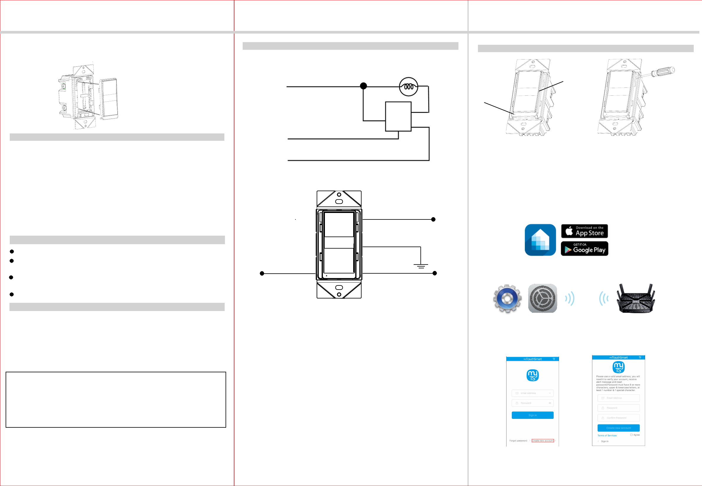
Single Switch Wiring Schematic
Wiring Diagram:
WARNINGS AND CAUTIONS
6. Check connections to be sure they are tight and no bare conductors are exposed.
7. Insert the JWF15S switch into the standard outlet box carefully.
8. Make sure the JWF15S switch to the box using the supplied screws.
9. Attach the wall plate.
10. Restore power at the circuit breaker and test the system.
White (Neutral)
Red
(Load)
Green (Ground)
Black (Line/Hot)
Wireless Home Automation Control Device
OPERATIONS
Manual Control
The switch paddle on the JWF15S allows the user to:
1, Turn ON/OFF the connected lighting.
1, To turn the connected lighting ON: Tap the top of the switch paddle.
2, To turn the connected lighting OFF: Tap the bottom of the switch paddle.
Perfect Replacement for regular wall switch, 120VAC, 15Amp
Manual and Remote ON/OFF control of any connected lighting and other electrical
electrical load
The JWF15S ON/OFF Switch is a perfect wireless manual and remote on/off control
replacement of regular wall switch, controlling incandescent, LED, fluorescent, ballast
and so on.
4. Disconnect the wiring from the existing switch.
5. Connect this JWF15S switch as shown in the wiring diagram: Black lead to hot wire,
white lead to neutral wire, red lead to load wire, green lead to ground wire.
1.WARNING : To avoid fire, shock, or death. High Voltage - Turn off power at circuit
breaker or fuse and test that power is off before wiring.
2. Remove wall plate and existing switch mounting screws.
3. Carefully remove the existing switch from the switch box.
Ground
Green
White
Neutral
Red
Load (to light fixture)
Black
Hot (from breaker)
LED Light
Switch Paddle
Supply Connection.....................................14 AWG wires, suitable for at least 75°C
Wire Strip Length.................................................................................16mm(5/8 in.)
Screw Torque................................................................................................20 lbf-in
Interchangeable Face Cover
Interchangeable Color Face Plate
To replace the face
cover, just use a
flat screwdriver to
pry-off the
interchangeable plate.
Voltage.............................................................................................. 120VAC, 60Hz
Incandescent..................................................................................................1000W
Resistive................................................................................................1800W(15A)
Motor.............................................................................................................. 1/2 HP
Standard Ballast............................................................................................1200VA
Electronic Ballast...................................................................................................5A
Operating Temperature.........................................................32°F~104°F(0°C~40°C)
Protocol.........................................................................................IEEE 802.11b/g/n
Wireless Type.............................................................................................. 2.4GHz
Be sure to read the instruction carefully before installation, and the manufacturer
will not be responsible for any product damage that does not follow the instruction
1. Wet hands are strictly prohibited.
2. Must work strictly according to the rated load.
3. Do not continue to work after self-disassembly of any nature and damage of
external forces.
After a power failure, the WF15S on/off switch returns to OFF state.
Please Note:
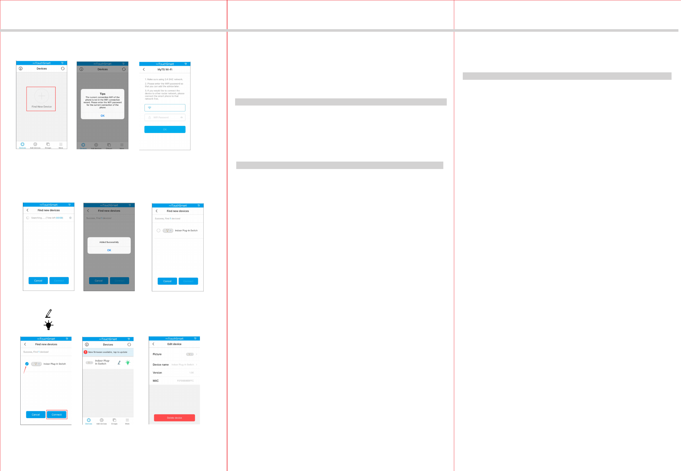
You can Turns your devices on or off at any time or anywhere have Internet using
the free MyTS App on your smartphone.
JWF15S
1. Download MyTS app from the App Store or Google Play.
2. Connect mobile device to your 2.4GHz WIFI network. Please note
this switch can only be connected to 2.4GHz network.
3. Launch MyTS and follow the in-app instructions to connect the
switch to your network.
MyTS App Control
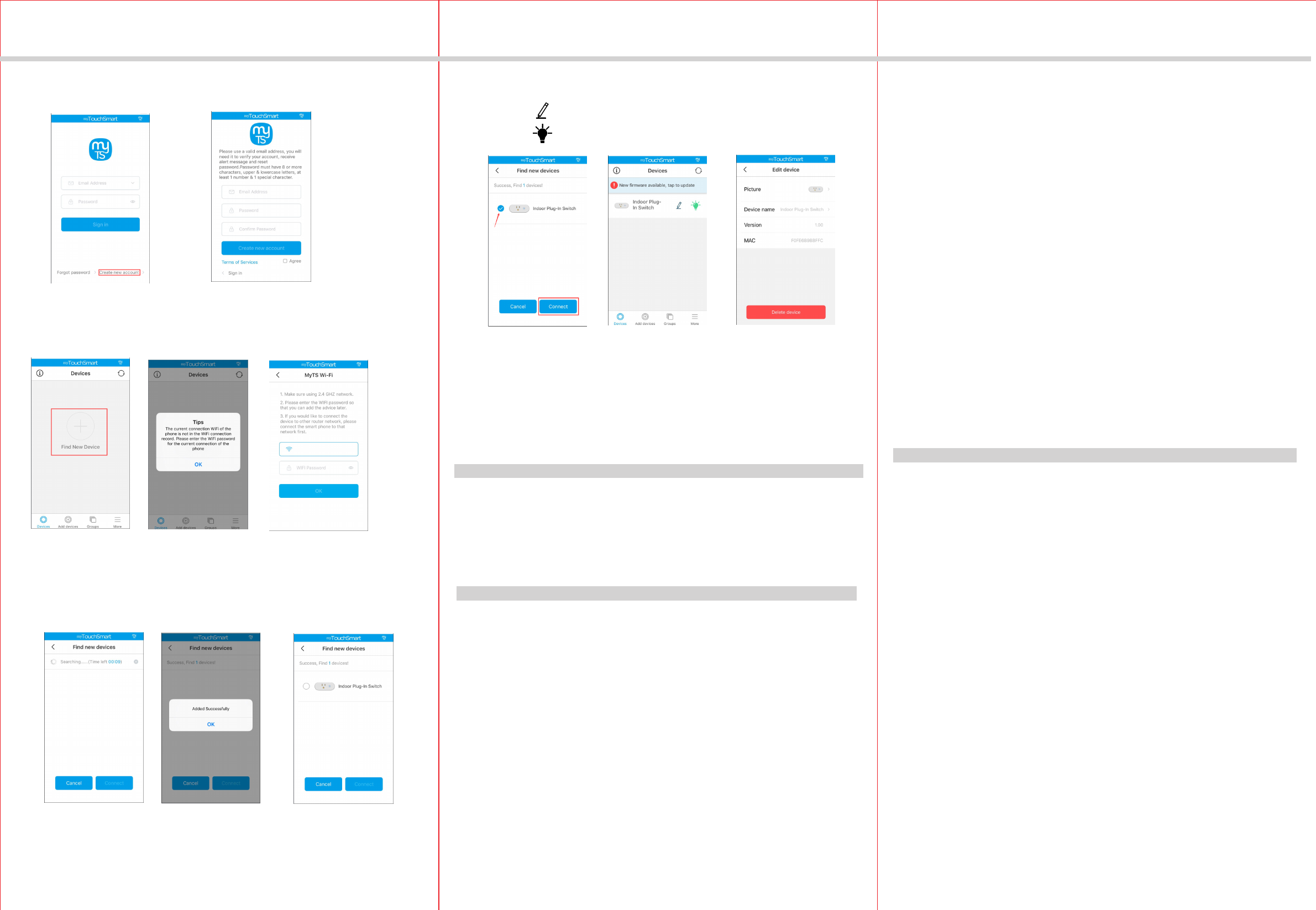
a. Login the MyTS, you need create a new account then sign in.
-05-
-04-
INSTALLATION INSTRUCTIONS
WARRANTY INFORMATION
Our company warranties its products to be free of defects in materials and workman
-ship for a period of two (2) years. There are no obligations or liabilities on the part
use or performance of this product or other indirect damages with respect to loss
of property, revenue, or profit, or cost of removal, installation or reinstallation.
of our company for consequential damages arising out of or in connection with the
Jun, 2018
b. Click the button “+” then enter your WIFI paasword
c. Pls tap the JWF15S up paddle above 10 seconds until the blue LED is in
a quick flashing state, then this switch can be added successfully.
d. Pls select this switch and then click the "Connect" button then finished .
Click the you can turn on or off the swich.
Click the you can edit this swich device.
1. During the process of adding device, you must select the correct name of WIFI
Please Note:
2. Now, this WIFI Switch can only be paired with one phone device.
router and fill in the correct WIFI password, otherwise the device will not be able
to add successfully.
LED INDICATION
Connecting to the network.
Quick Flashing in Blue:
Blue LED keep lighting: Connected to the network.
Solid Blue:
Off:
The WIFI Switch is switched on.
The WIFI Switch is switched off.
FCC COMPLIANCE STATEMENT
This device complies with Part 15 of the FCC Rules. Operation is subject to the
following two conditions: 1. This device may not cause interference, and 2. This
cause undesired operation.
device must accept any interference received, including interference that may
FCC Radiation Exposure Statement:
This equipment complies with FCC radiation exposure limits set forth for an
RF Exposure: A distance of 20 cm shall be maintained between the antenna
uncontrolled environment. This equipment should be installed and operated
with minimum distance 20cm between the radiator & your body.
and users, and the transmitter module may not be co-located with any other
transmitter or antenna.
Federal Communication Commission Interference Statement
The equipment has been tested and found to comply with the limits for a class B
B Digital Device, pursuant to part 15 of the FCC Rules. These limits are designed to
provide reasonable protection against harmful interference in a residential installation.
This equipment uses, generates and can radiate radio frequency energy and, if not
installed and used in accordance with the instruction, may cause harmful interference
occur in a particular installation. If this equipment does cause harmful interference
to radio or television reception, which can be determined by turning the equipment
to radio communication. However, there is no guarantee that interference will not
off and on, the user is encouraged to try to correct the interference by one or
more of the following measures:
- Reorient or relocate the receiving antenna.
- Increase the separation between the equipment and receiver.
- Connect the equipment into an outlet on a circuit different from that to which the
receiver is connected.
- Consult the dealer or an experienced radio/TV technician for help.
FCC Caution:
Non-modification Statement:
Any changes or modifications not expressly approved by the party responsible
for compliance could void the user's authority to operate this equipment.
INSTALLATION INSTRUCTIONS
-02- -03--01-
DESCRIPTION
FEATURES
JWF15S-3W
On/Off Switch
SPECIFICATIONS
INSTALLATION
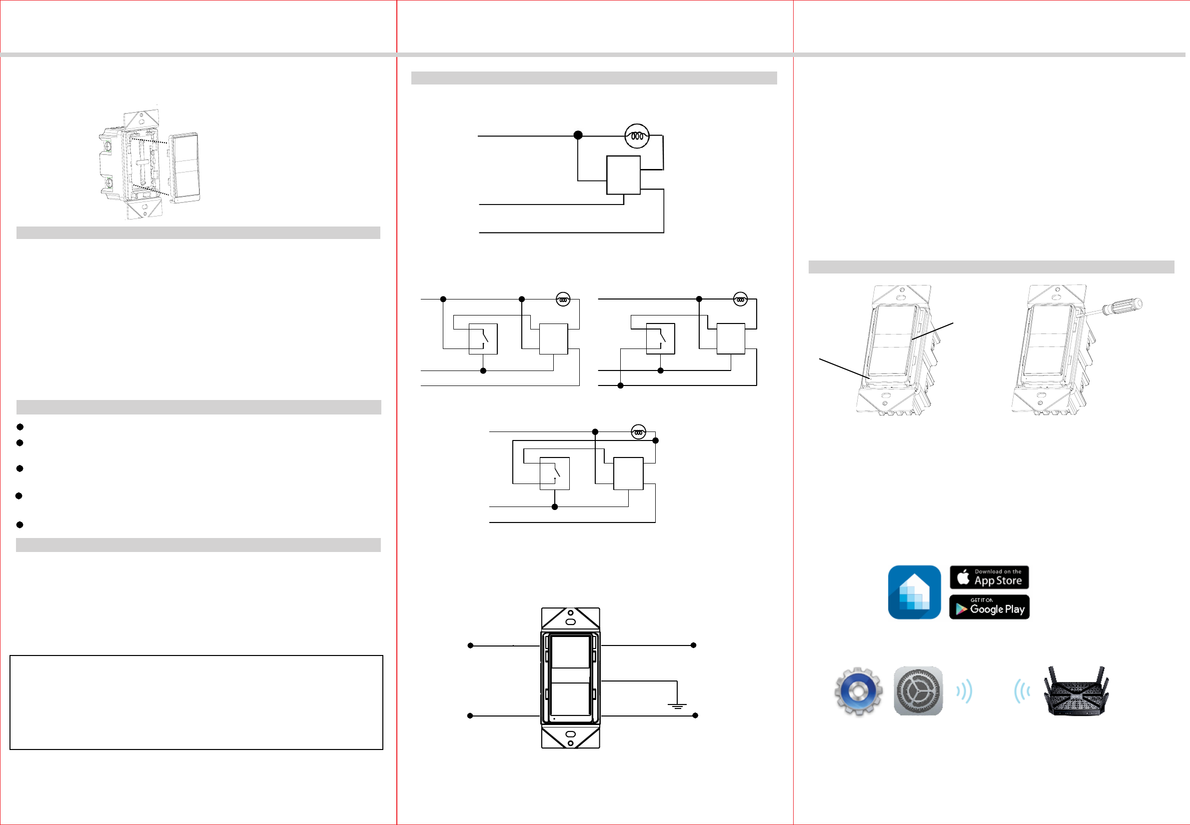
Single Switch Wiring Schematic
Wiring Diagram:
WARNINGS AND CAUTIONS
6. Check connections to be sure they are tight and no bare conductors are exposed.
7. Insert the JWF15S-3W switch into the standard outlet box carefully.
8. Make sure the JWF15S-3W switch to the box using the supplied screws.
9. Attach the wall plate.
10. Restore power at the circuit breaker and test the system.
White (Neutral)
Red
(Load)
Green (Ground)
Black (Line/Hot)
Wireless Home Automation Control Device
OPERATIONS
Manual Control
The switch paddle on the JWF15S-3W allows the user to:
1, Turn ON/OFF the connected lighting.
1, To turn the connected lighting ON: Tap the top of the switch paddle.
2, To turn the connected lighting OFF: Tap the bottom of the switch paddle.
Perfect Replacement for regular wall switch, 120VAC, 15Amp
Manual and Remote ON/OFF control of any connected lighting and other electrical
electrical load
Can be used for signal pole or 3- Way (Multi-location) with Auxiliary Switch (sold
The JWF15S-3W ON/OFF Switch is a perfect wireless manual and remote on/off
control replacement of regular wall switch, controlling incandescent, LED, fluorescent,
ballast and so on. This JWF15S-3W ON/OFF Switch works with 3-Way Auxiliary
4. Disconnect the wiring from the existing switch.
5. Connect this JWF15S-3W switch as shown in the wiring diagram: Black lead to hot
wire, white lead to neutral wire, red lead to load wire, green lead to ground wire.
1.WARNING : To avoid fire, shock, or death. High Voltage - Turn off power at circuit
breaker or fuse and test that power is off before wiring.
2. Remove wall plate and existing switch mounting screws.
3. Carefully remove the existing switch from the switch box.
Traveler works with 3-way Auxiliary Switch control( sold separately).
Yellow
Ground
Green
Traveler
White
Neutral
Red
Load (to light fixture)
Black
Hot (from breaker)
LED Light
Switch Paddle
Supply Connection.....................................14 AWG wires, suitable for at least 75°C
Wire Strip Length.................................................................................16mm(5/8 in.)
Screw Torque................................................................................................20 lbf-in
Interchangeable Face Cover
Interchangeable Color Face Plate
To replace the face
cover, just use a
flat screwdriver to
pry-off the
interchangeable plate.
Voltage.............................................................................................. 120VAC, 60Hz
Incandescent..................................................................................................1000W
Resistive................................................................................................1800W(15A)
Motor.............................................................................................................. 1/2 HP
Standard Ballast............................................................................................1200VA
Electronic Ballast...................................................................................................5A
Operating Temperature.........................................................32°F~104°F(0°C~40°C)
Protocol.........................................................................................IEEE 802.11b/g/n
Wireless Type.............................................................................................. 2.4GHz
your home, condominiums and apartment.
Switch that reducing energy consumption, enhancing the value of technology of
Be sure to read the instruction carefully before installation, and the manufacturer
will not be responsible for any product damage that does not follow the instruction
1. Wet hands are strictly prohibited.
2. Must work strictly according to the rated load.
3. Do not continue to work after self-disassembly of any nature and damage of
external forces.
After a power failure, the WF15S-3W on/off switch returns to OFF state.
Please Note:
separately)
White(Netural)
Red(Load)
Traveler(Yellow)
SWITCH
Green(Groud)
Black(Hot)
White(Netural)
Traveler(Yellow) Red(Load)
SWITCH
Black(Hot)
Green(Groud)
White(Netural)
Traveler(Yellow) Red(Load)
SWITCH
Black(Hot)
Green(Groud)
Wiring Method 1 Wiring Method 2
Wiring Method 3
You can Turns your devices on or off at any time or anywhere have Internet using
the free MyTS App on your smartphone.
JWF15S-3W
JWF15S-3W
3-Way Wiring Schematic using one JWF15S and one 3-way Auxiliary Switch
1. Download MyTS app from the App Store or Google Play.
2. Connect mobile device to your 2.4GHz WIFI network. Please note
this switch can only be connected to 2.4GHz network.
3. Launch MyTS and follow the in-app instructions to connect the
switch to your network.
MyTS App Control
JWF15S-3W
JWF15S-3W
-05-
-04-
INSTALLATION INSTRUCTIONS
WARRANTY INFORMATION
Our company warranties its products to be free of defects in materials and workman
-ship for a period of two (2) years. There are no obligations or liabilities on the part
use or performance of this product or other indirect damages with respect to loss
of property, revenue, or profit, or cost of removal, installation or reinstallation.
of our company for consequential damages arising out of or in connection with the
Jun, 2018
a. Login the MyTS, you need create a new account then sign in.
b. Click the button “+” then enter your WIFI paasword
c. Pls tap the JWF15S-3W up paddle above 10 seconds until the blue LED is in
a quick flashing state, then this switch can be added successfully.
d. Pls select this switch and then click the "Connect" button then finished .
Click the you can turn on or off the swich.
Click the you can edit this swich device.
1. During the process of adding device, you must select the correct name of WIFI
Please Note:
2. Now, this WIFI Switch can only be paired with one phone device.
router and fill in the correct WIFI password, otherwise the device will not be able
to add successfully.
LED INDICATION
Connecting to the network.
Quick Flashing in Blue:
Blue LED keep lighting: Connected to the network.
Solid Blue:
Off:
The WIFI Switch is switched on.
The WIFI Switch is switched off.
FCC COMPLIANCE STATEMENT
This device complies with Part 15 of the FCC Rules. Operation is subject to the
following two conditions: 1. This device may not cause interference, and 2. This
cause undesired operation.
device must accept any interference received, including interference that may
FCC Radiation Exposure Statement:
This equipment complies with FCC radiation exposure limits set forth for an
RF Exposure: A distance of 20 cm shall be maintained between the antenna
uncontrolled environment. This equipment should be installed and operated
with minimum distance 20cm between the radiator & your body.
and users, and the transmitter module may not be co-located with any other
transmitter or antenna.
Federal Communication Commission Interference Statement
The equipment has been tested and found to comply with the limits for a class B
B Digital Device, pursuant to part 15 of the FCC Rules. These limits are designed to
provide reasonable protection against harmful interference in a residential installation.
This equipment uses, generates and can radiate radio frequency energy and, if not
installed and used in accordance with the instruction, may cause harmful interference
occur in a particular installation. If this equipment does cause harmful interference
to radio or television reception, which can be determined by turning the equipment
to radio communication. However, there is no guarantee that interference will not
off and on, the user is encouraged to try to correct the interference by one or
more of the following measures:
- Reorient or relocate the receiving antenna.
- Increase the separation between the equipment and receiver.
- Connect the equipment into an outlet on a circuit different from that to which the
receiver is connected.
- Consult the dealer or an experienced radio/TV technician for help.
FCC Caution:
Non-modification Statement:
Any changes or modifications not expressly approved by the party responsible
for compliance could void the user's authority to operate this equipment.