WENZHOU MTLC ELECTRIC APPLIANCES WF500D Dimmer Switch User Manual
WENZHOU MTLC ELECTRIC APPLIANCES CO., LTD. Dimmer Switch Users Manual
Users Manual
WIFI Control Device
INSTALLATION INSTRUCTIONS
-03-
-01-
DESCRIPTION
FEATURES
WF500D
Voltage...............................................................................................120VAC, 60Hz
Incandescent.....................................................................................................600W
Operating Temperature.........................................................32°F~104°F(0°C~40°C)
SPECIFICATIONS
-02-
Wireless Home Automation
Perfect Replacement for regular wall ON/OFF & Dim switch, 120VAC
Manual and Remote ON/OFF& Dim control of any permanently installed incandescent,
dimmable LED and CFL lamp fixture
Preset light level option allows the dimmer will turn on to the light level that it was
adjusted to the previous time when the light was on
The WF500D Dimmer Switch is a perfect wireless manual and remote on/off/ dim
bright control replacement of regular on/off and dimmer switch, controlling incandescent,
dimmable LED and CFL. Sliding Air-Gap switch to a totally disconnect power while
1. WARNING : To avoid fire, shock, or death. High Voltage - Turn off power at circuit
breaker or fuse and test that power is off before wiring.
3. Remove wall plate and existing switch mounting screws.
4. Carefully remove the existing switch from the switch box.
5. Disconnect the wiring from the existing switch.
6. Connect the dimmer switch as shown in the wiring diagram: Black lead to hot
wire, white lead to neutral wire, red lead to load wire, green lead to ground wire.
7. Check connections to be sure they are tight and no bare conductors are exposed.
8. Insert the WF500D dimmer switch into the standard outlet box carefully.
9. Make sure the WF500D dimmer switch to the box using the supplied screws.
10. Attach the wall plate.
11. Restore power at the circuit breaker and test the system.
circuit wiring and circuit loading. No specific recommendation on product selection
and there are no warranties of performance or compatibility implied.
Supply Connection...............................................................................14 AWG wires
Wire Strip Length..................................................................................16mm(5/8 in.)
Screw Torque.................................................................................................20 lbf-in
LED dimming performance may vary based upon dimmer type, model, manufacturer,
Air Gap Switch
During normal operation, there is a small amount of power passing through the
switch to the load even when the dimmer switch is turned off. The WF500D has an
air gap switch on the lower right side to completely disconnect power to the load.
for the dimmer to function and control the lighting.
Slide the air gap switch to left to disconnect the power while replacing light bulbs
and slide it to right for normal operation. The air gap switch must be all the way in
Air-Gap Switch feature meets UL requirement and disconnect power from load
locally.
replacing light bulbs and preventing from leakage current from the fixture(s). The
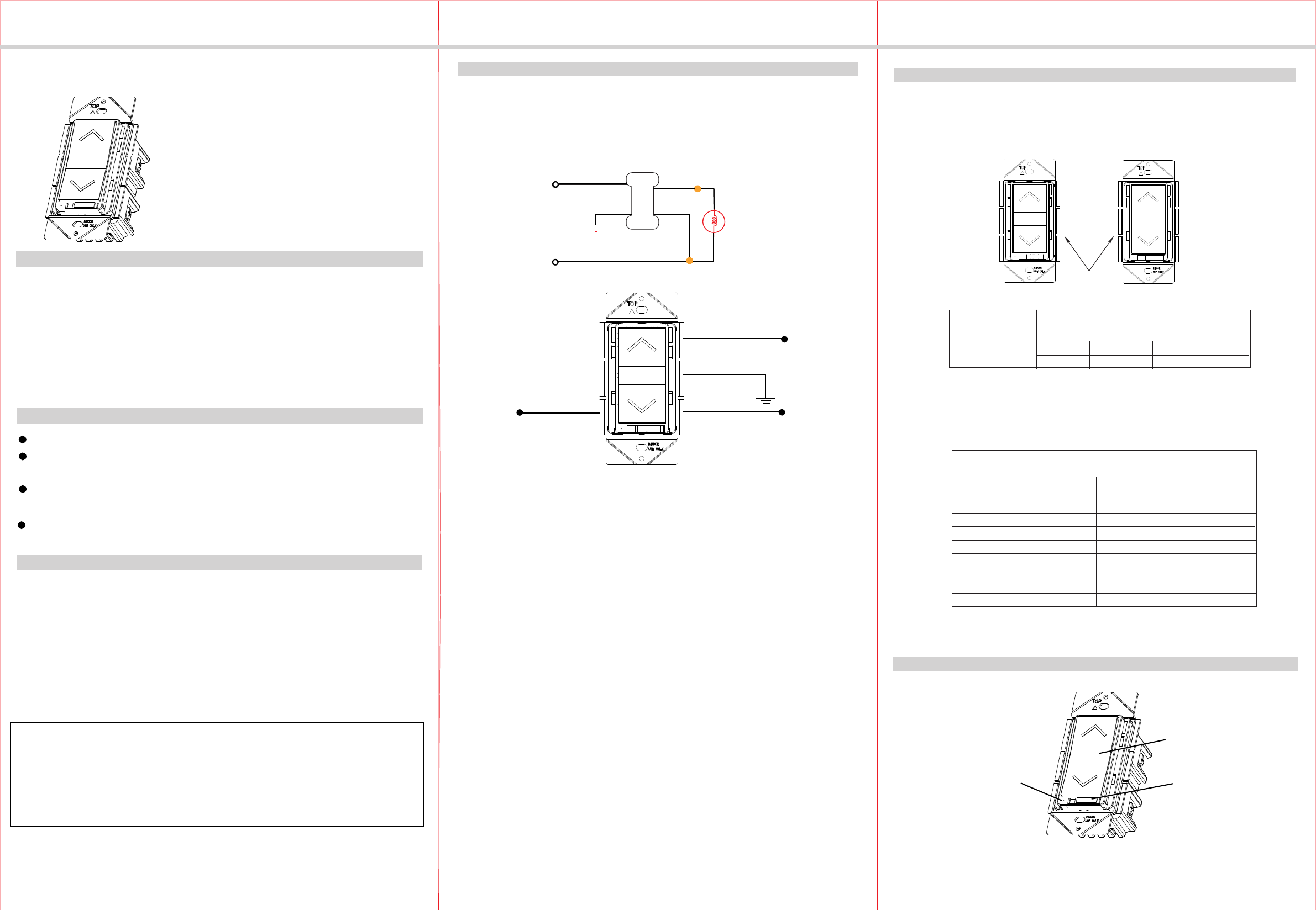
Wiring Diagram:
Ground
Green
Red
Load (to light fixture)
Black
Hot (from breaker)
White
Neutral
WARNINGS AND CAUTIONS
INSTALLATION
This WF500D dimmer switch may be used in new installations or replace an existing
wall switch.
Light
Typical Dimmer Wiring Schematic:
Red
Black
Green
White
120 VAC
60 Hz
MULTIGANG INSTALLATION
When installing more than one control in the same wall box, it may be necessary
to remove the side tabs before installing (see below). Using pliers, bend each tab
back and forth until they break off. Repeat for each tab to be removed. Removal
of tabs WILL REDUCE MAXIMUM LOAD CAPACITY.
Tabs Removed for Mulitgang installation
Dimmable LED/CFL
Load Capacity when Tabs are removed from:
0 Sides
1 Side
2 Sides
150W 150W150W
LED/CFL Derating Chart
When using the Dimmer to control LED/CFL lights in conjunction with another Dimmer
to control Incandescent /Halogen lights follow this Derating Chart for Maximum
Capacitiy on EACH device.
Then the Maximum COMBINED Wattaged for the
Incandescent/Halogen bulbs on EACH attached dimmer:
If NO Tabs are
removed then
Max Wattage is:
If 1 side of Tabs
are removed then
Max Wattage is:
If 2 sides of Tabs
are removed then
Max Wattage is:
0W
1-25W
26-50W
51-75W
76-100W
101-125W
126-150W
600W
500W
400W
300W
200W
100W
0W
500W
400W
300W
200W
100W
50W
0W
400W
300W
200W
100W
50W
0W
0W
If the combined
Wattage of ALL
LED/CFL bulbs
on 1 dimmer is:
If you are using ONLY LED/CFL bulbs on ALL Dimmers, DO NOT USE this Derating
Chart. Follow the LED/ CFL Derating Chart.
CFL/LED/Electronic self-ballasted.............................................................2A (150W)
Protocol...........................................................................................IEEE 802.11b/g/n
Wireless Type................................................................................................ 2.4GHz
Be sure to read the instruction carefully before installation, and the manufacturer
will not be responsible for any product damage that does not follow the instruction
1. Wet hands are strictly prohibited.
2. Must work strictly according to the rated load.
3. Do not continue to work after self-disassembly of any nature and damage of
external forces.
LED indicator
Dimmer Switch Paddle
Air Gap Switch
OPERATIONS
Dimmer Switch
2. CAUTION : To Reduce The Risk of Overheating and Possible Damage to Other
Equipment, Do Not Install to Control a Receptacle, a Motor-Operated Appliance
or a Fluorescent Lighting Fixture or a Transformer Supplied Appliance.
INSTALLATION INSTRUCTIONS
LED INDICATION
Apr, 2018
1. During the process of adding device, you must select the correct name of WIFI
Please Note:
Restoring Factory Defaults
2. Now, this WIFI Dimmer is paired with one phone device. If you want to control
" Device Sharing".
Please note: pressing and holding the dimmer switch paddle until the light intensity
is at the minimum setting does not turn the power OFF, you must still tap (short
press) the bottom of the dimmer switch paddle to turn the power OFF.
WARRANTY INFORMATION
Our company warranties its products to be free of defects in materials and workman
-ship for a period of two (2) years. There are no obligations or liabilities on the part
use or performance of this product or other indirect damages with respect to loss of
property, revenue, or profit, or cost of removal, installation or reinstallation.
of our company for consequential damages arising out of or in connection with the
Manual Control
The WF500D dimmer switch allows the user to:
Turn ON/OFF and control the brightness level of the connected lighting.
1. To turn the connected lighting ON: Tap the top of the dimmer switch paddle.
2. To turn the connected lighting OFF: Tap the bottom of the dimmer switch paddle
3. To brighten the connected lighting: Press and hold the top of the dimmer switch
paddle, release when desired level is achieved.
4. To dim the connected lighting: Press and hold the bottom of the dimmer switch
paddle, release when desired level is achieved.
The LED indicator will be turned on in blue.
again. The LED indicator will be turned off.
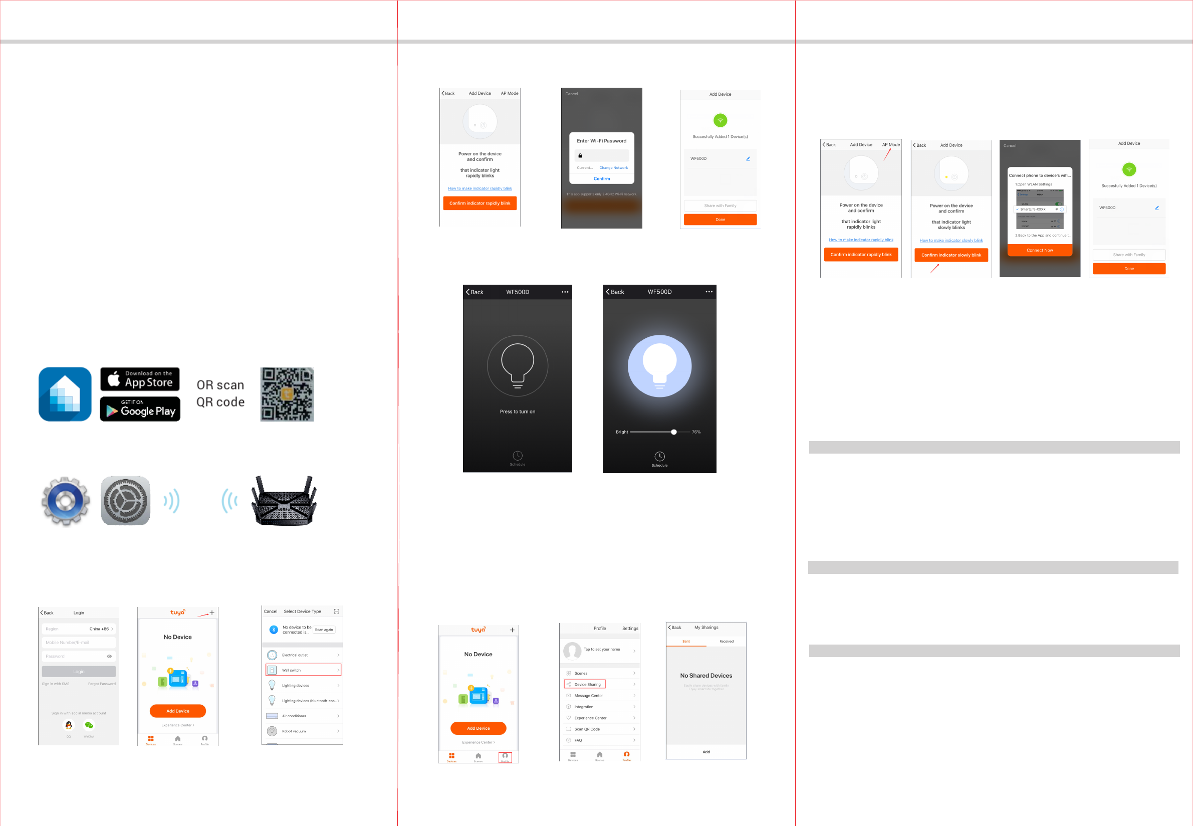
Tuya Smart App Control
1. Download Tuya Smart app from the App Store or Google Play.
2. Connect mobile device to your 2.4GHz WIFI network. Please note this
Smart Dimmer Switch can only be connected to 2.4GHz network.
3. Launch Tuya and follow the in-app instructions to connect the
Smart Dimmer Switch to your network.
a. Login the Tuya b. Click the button “+” c. Select the "Wall switch"
d. Click the bottom button e. Enter your Wifi password f. Finished
4. When the device is added successfully, this WIFI Dimmer can be turned ON/OFF
and dimmed.
router and fill in the correct WIFI password, otherwise the device will not be able
to add successfully.
the WIFI Dimmer by different phones, click the "profile" then chose the
please press the top or bottom button 5 times continuously, then press and hold
at the sixth time then release, the LED indicator in green and flashes quickly.
Please Note:
in green will flash quickly which means that the Dimmer is searching for WIFI. It will
stop flashing and turn off when WIFI is connected successfully for 5 seconds. when
-06-
-04- -05-
20180426-00089
When power is reconnected after the interruption, the LED indicator
This device complies with Part 15 of the FCC Rules. Operation is subject to the
following two conditions: 1. This device may not cause interference, and 2. This
cause undesired operation.
FCC COMPLIANCE
device must accept any interference received, including interference that may
When power on the device and confirm that indicator light if rapidly blinks, if not
the LED indicator in solid green that means your network anomaly, pls check the
network.
3. When the device fail to add in the App, please try to enter the AP mode.
Before enter the AP mode please press the top or bottom button 5 times
continuously, then press and hold at the sixth for 5 seconds then release,
the LED indicator in green and slowly blinks.
Connecting to the network.
Quick Blinking Green:
Green bright after 2 seconds off: Connected to the network.
Solid Blue:
Off:
The WIFI Dimmer is switched on.
The WIFI Dimmer is switched off.
Soild Green: Network abnormaly .
AP mode.
Slow Blinking Green:
Federal Communication Commission Interference Statement
This equipment has been tested and found to comply with the limits for a Class B digital device, pursuant
to Part 15 of the FCC Rules. These limits are designed to provide reasonable protection against harmful
interference in a residential installation. This equipment generates, uses, and can radiate radio frequency
energy and, if not installed and used in accordance with the instructions, may cause harmful interference
to radio communications. However, there is no guarantee that interference will not occur in a particular
installation. If this equipment does cause harmful interference to radio or television reception, which can
be determined by turning the equipment off and on, the user is encouraged to try to correct the
interference by one or more of the following measures:
• Reorient or relocate the receiving antenna.
• Increase the separation between the equipment and receiver.
• Connect the equipment into an outlet on a circuit different from that to which the receiver is connected.
• Consult the dealer or an experienced radio/TV technician for help.
Caution: Any changes or modifications not expressly approved by the party responsible for compliance
could void the user's authority to operate this equipment.
FCC Radiation Exposure Statement:
This equipment complies with FCC radiation exposure limits set forth for an uncontrolled environment.
This equipment should be installed and operated with minimum distance 20cm between the radiator &
your body.
RF Exposure: A distance of 20 cm shall be maintained between the antenna and users, and the
transmitter module may not be co-located with any other transmitter or antenna.