WG security WG58PUG EAS System User Manual
WG Security Products, Inc EAS System
User Manual

58Khz
Pro-GuardTM & Uni-GuardTM
Instruction Manual
[24vac Low Voltage with 110.220vac Transformer]
Version 2004 April
Manual Part Number: WG-PRG-IM
(042004A)
WG SECURITY PRODUCTS INC.
3031 Tisch Way, Suite 602, San Jose, CA 95128 (USA)
http://www.wgspi.com

TECHNICAL SUPPORT CONTACT INFORMATION
North America
South America
Tel: 818-763-9186
Fax: 818-255-0514
Email: svc@sensorsense.com
Rest of World
Tel: 408-241-8000
Fax: 408-241-8082
Email: support@wgspi.com
WARRANTY DISCLAIMER
WG Security Product Inc. makes no representation o
r
warranty with respect to the contents hereof and
specifically disclaims any implied warranties o
f
merchantability or fitness for any particular purpose.
Further, WG Security Product Inc. reserves the right to
revise this publication and make changes from time to
time in the content hereof without obligation of WG
Security Product Inc. to notify any person of such
revision or changes.
Important Notice!
Due to regulations of FCC 15.21, any changes o
r
modifications not expressly approved by the party
responsible for compliance will void the user's
authority to operate the equipment.
TABLE OF CONTENTS
CHAPTER ONE ........................................................................................... 1
System Overview.............................................................................................. 1
Features & Benefits .......................................................................................... 2
Pro-Guard System Parts List ............................................................................ 3
Uni-Guard System Parts List ............................................................................ 4
CHAPTER TWO........................................................................................... 5
Installation Procedures ..................................................................................... 5
Step-Down Transformer Box......................................................................... 5
Transformer Cable Connection..................................................................... 6
Step-Down Transformer Capacity................................................................. 6
System Connections (Pro-Guard & Uni-Guard)............................................ 7
Optional Power Connection for Pro-Guard ................................................... 8
Optional Split System Connection for Pro-Guard (two Tx’s & one Rx) ........ 9
Optional IR Counting System Configuration (Pro-Guard & Uni-Guard) ..... 10
Power Cord Notices........................................................................................ 11
North American Power Supply Cords ......................................................... 11
International Power Supply Cord ................................................................ 11
Fuse Replacement Information....................................................................... 16
IR Control Keyboard Function Description & Default Parameters Table ....... 19
Tuning Procedures & Tips .............................................................................. 21
Remote Control Programming........................................................................ 22
Pro-Guard & Uni-Guard Installation Manual
1
CHAPTER ONE
System Overview
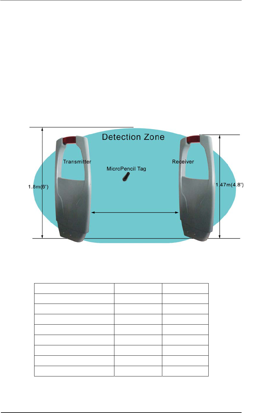
Pro-Guard and Uni-Guard Electronic Article Surveillance systems operate with any 58Khz
acousto-magnetic tag. Both systems are plug-and-play, eliminating the need for expensive
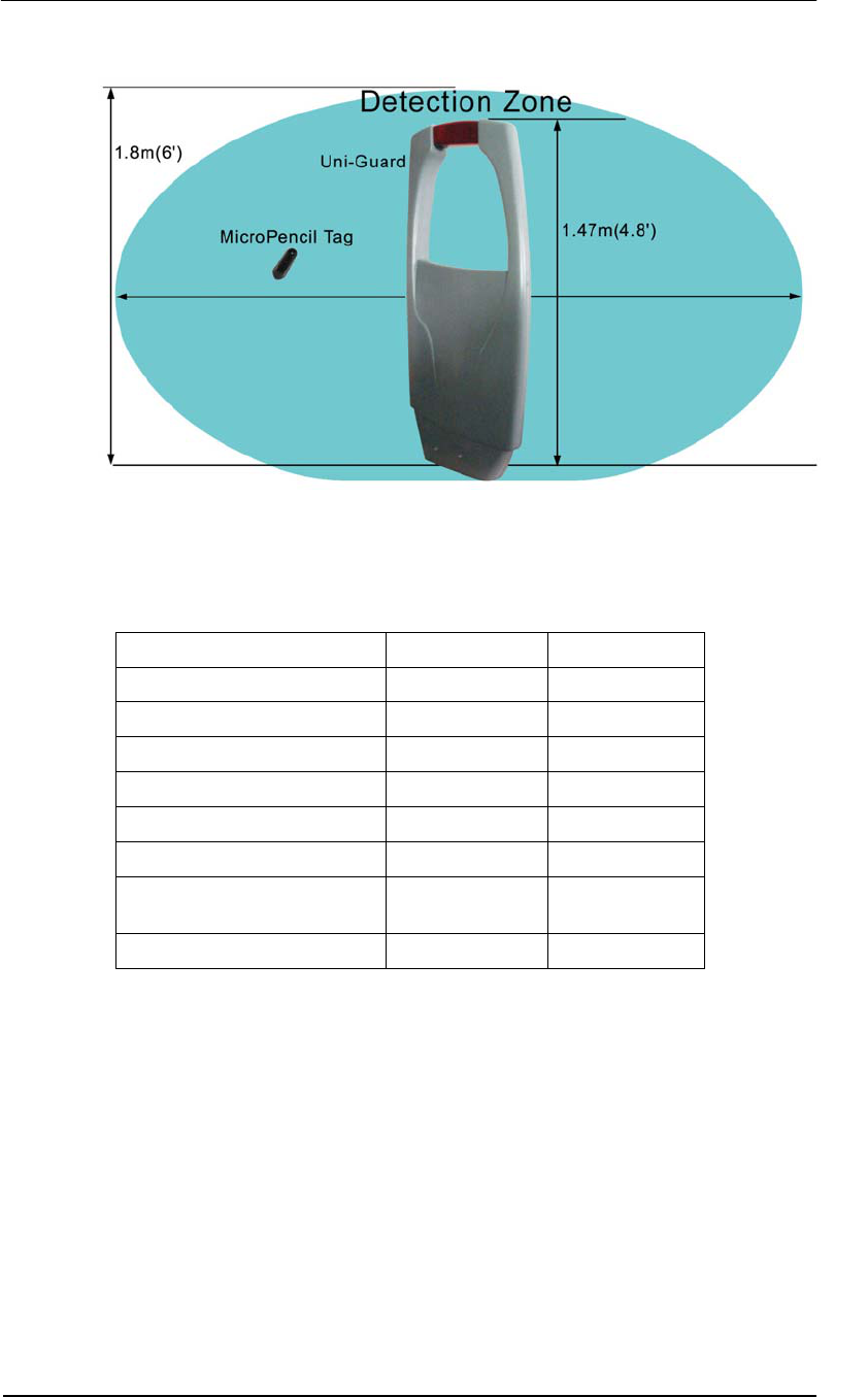
technicians. Pro-Guard is a dual pedestal system whereas Uni-Guard is a single pedestal
transceiver system.
The fully digital Pro-Guard and Uni-Guard systems are today’s most technically advanced
58Khz pedestal systems on the market. Both systems are fully digital, software driven, and
have the latest DSP technology that constantly checks the environment, eliminating false
alarms that are common with competing systems.
Technical Data Europe USA
Height 1470mm 58”
Width 710mm 28”
Thickness 120mm 7.1”
Weight 10Kg 22lbs
Power 220-240vac 100-120vac
Operating Frequency 58Khz 58Khz
Micro Pencil Tag Detection 2.6 meters 9 feet
Operating Temperature 0º C to 30º C 32º F to 86º F
9 Feet (2.6m)
Pro-Guard & Uni-Guard Installation Manual
2
Technical Data Europe USA
Height 1470mm 58”
Width 710mm 28”
Thickness 120mm 7.1”
Weight 10Kg 22lbs
Power 220-240vac 100-120vac
Operating Frequency 58Khz 58Khz
Micro Pencil Tag Detection 1.2 meters on
either side.
4 feet on either
side.
Operating Temperature 0º C to 49º C 32º F to 120º F
Features & Benefits
• Self tuning electronics
• Software driven
• Network Access for remote tuning
• Built-in alarm
• Port for driving an external alarm
• Constructed of strong, light ABS fire retardant molding
• Compatible with all 58Khz acousto-magnetic labels and hard tags.
• Greater detection in all tag orientations
4 Feet (1.2m) 4 Feet (1.2m)
Pro-Guard & Uni-Guard Installation Manual
3
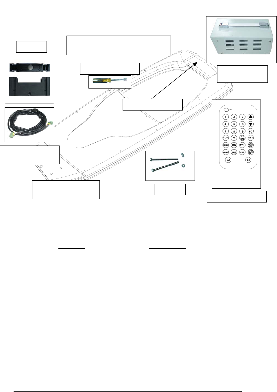
Pro-Guard System Parts List
Part Name Order Number
1 Transmitter Pedestal WG-PRG-PC-T
2 Receiver Pedestal WG-PRG-PC-R
3 Clear Alarm Cover WG-PRG-WD
4 Base WG-PRG-BS
5 Remote Control WG-MG-RC OLD
6 Interconnection Connector WG-MG-ICC
7 Pedestal Power Cable
Connector
WG-PRG-PLC
8 Installation Tool WG-MG-IT
9 Field Indicator Pen WG-MG-FP
10 Interconnection Line WG-MG-CC
11 Instruction Manual WG-PRG-M
12 24vac Transformer WG-PRG-TR
Base (2)
Pedestal Power Cable & Connector (2)
Transformer Primary Power Cable (1)
Installation Tool (1)
Clear Alarm Cover
24vac
Transformer (1)
Remote Control (1)
Bolts (8)
Transmitter & Receiver
Pedestals (2)
Interconnection Line
& Connector (2)
Pro-Guard & Uni-Guard Installation Manual
4
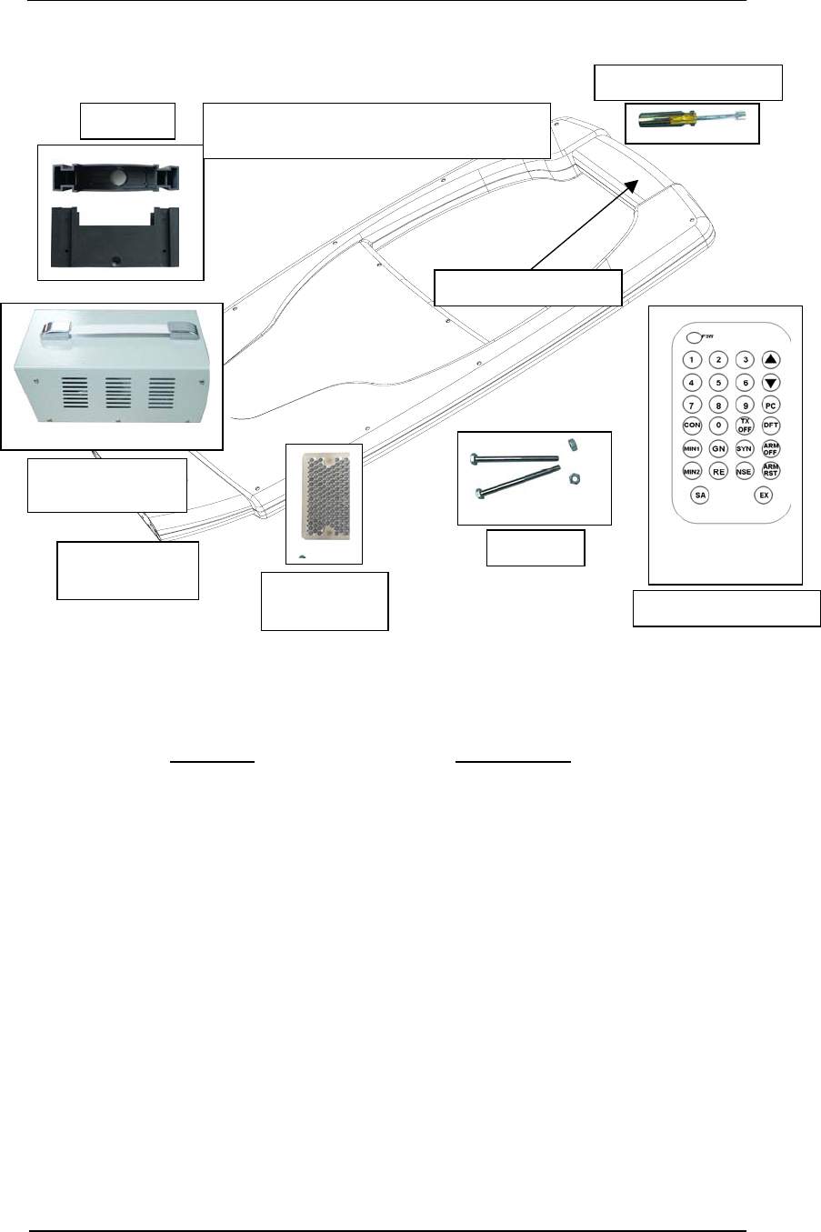
Uni-Guard System Parts List
Part Name Order Number
1 Transceiver Pedestal WG-UNG-PC
2 Clear Alarm Cover WG-PRG-WD
3 Base WG-PRG-BS
4 Remote Control WG-MG-RC OLD
5 Pedestal Power Cable
Connector
WG-PRG-PLC
6 Installation Tool WG-MG-IT
7 Field Indicator Pen WG-MG-FP
8 Instruction Manual WG-PRG-M
9 24vac Transformer WG-PRG-TR
10 IR Mirror Reflector WG-UNG-MIR
Base (1) Pedestal Power Cable & Connector (1)
Transformer Primary Power Cable (1)
Installation Tool (1)
Clear Alarm Cover
24vac
Transformer (1)
Remote Control (1)
Bolts (4)
IR Mirror
Reflector (1)
Pedestal
Transceiver (1)
Pro-Guard & Uni-Guard Installation Manual
5
CHAPTER TWO
Installation Procedures
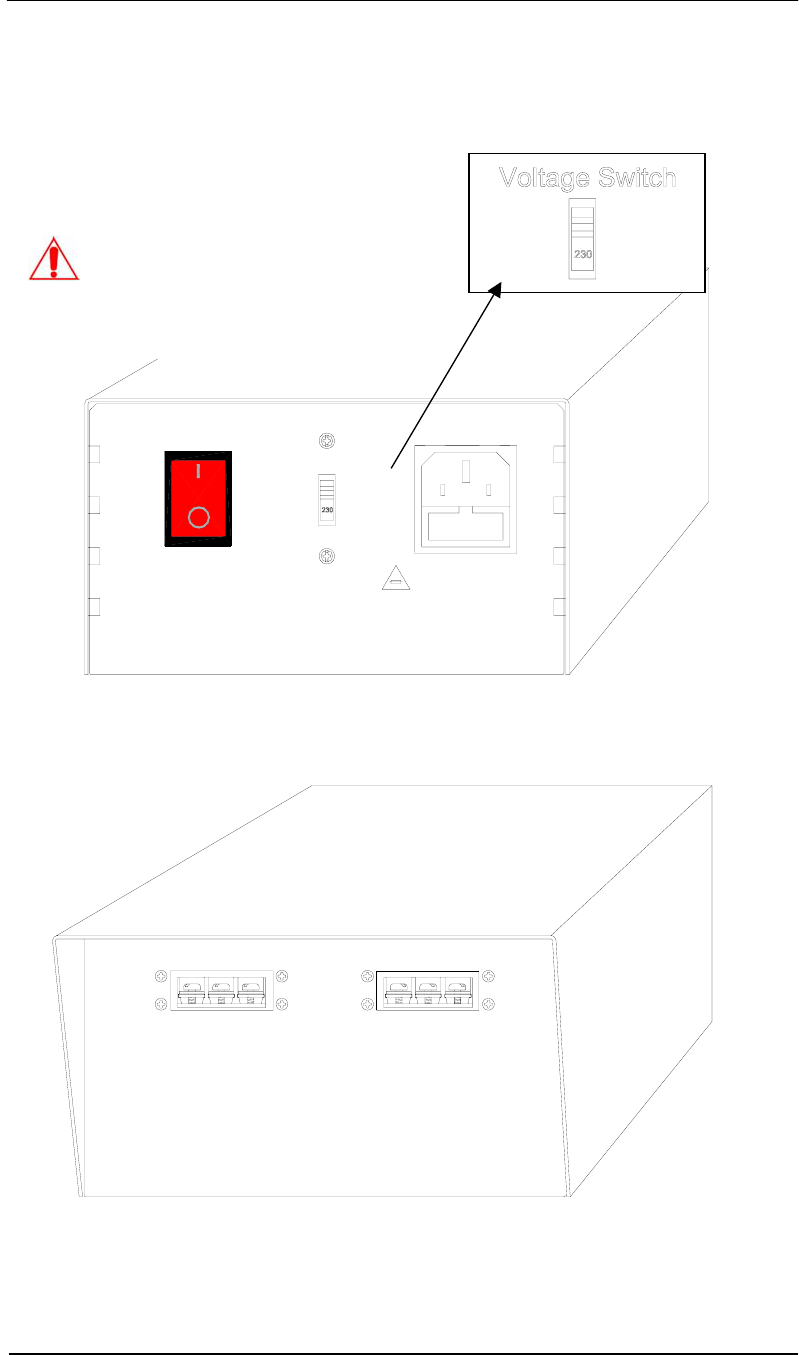
Step-Down Transformer Box
Fuse replacement
Extend fuse (time-delay fuse)
5mmx20mm 3.15A
Equipment shall be electrically disconnected from
the branch-circuit supply when replacing the fuse.
WARNING - TO REDUCE THE RISK OF DAMAGE. REPLACE
ONLY WITH SAME TYPE AND RATING OF FUSE.
OFF
ON
VOLTAGE SWITCH
AC POWER
24VAC OUTPUT 2
0V GND 24V0V GND 24V
24VAC OUTPUT 1
Caution:
The Voltage Switch is used to set the
system for the appropriate AC input.
North America – Set the switch to 115.
Europe – Set the switch to 230.
Pro-Guard & Uni-Guard Installation Manual
6
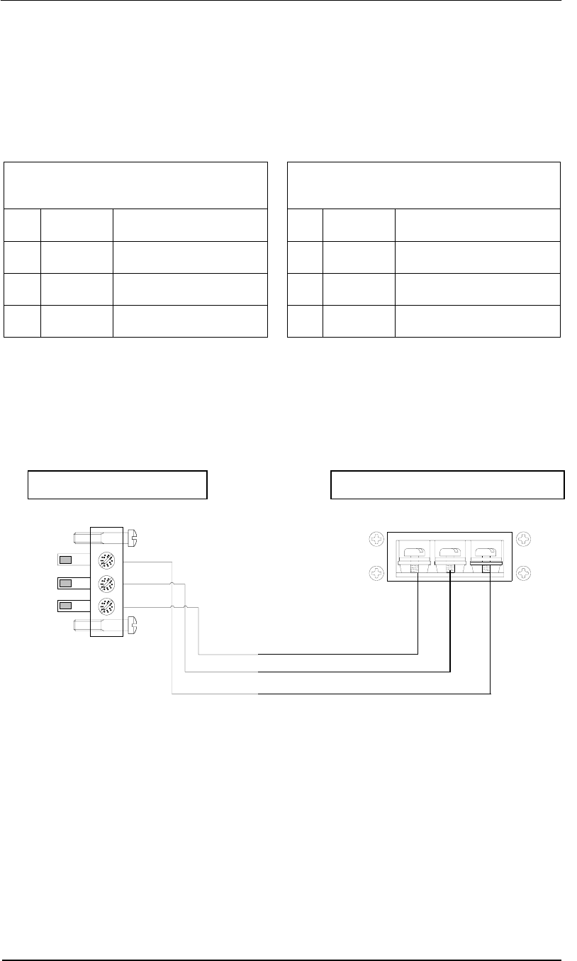
Transformer Cable Connection
Connect the three pins of the power connector to the corresponding terminals of the
transformer connector. The ground pins from both must be connected, but the 0V and 24V
terminals from the step-down transformer can be swapped to change the polarity of the
system.
3-Pin Power Connector Layout 3-Terminal Transformer
Connector Layout
Pin Function Color Pin Function Color
1 “N or L“ * Blue/Brown 1 0V Blue/Brown
2 Ground Green w/Yellow Stripe 2 Ground Green w/Yellow Stripe
3 “L or N” * Brown/Blue 3 24V Brown/Blue
(180 degrees phase switch)
* Note: Pin 1 and Pin 3 of the power connector are equivalent to former N and L
terminals for 110/220vac systems. Switching them will switch the system’s phase 180
degrees; same as former 110/220vac systems.
Step-Down Transformer Capacity
• Pro-Guard: Maximum 1 Transformer per Transmitter/Receiver pair.
• Uni-Guard: Maximum 1 Transformer per Uni-Guard.
Red
Green
Blue
Pin 1
24VAC OUTPUT
0V GND 24V
Pin 1
Brown
3-Pin Power Connector Transformer 24V Output Terminal
Pro-Guard & Uni-Guard Installation Manual
7
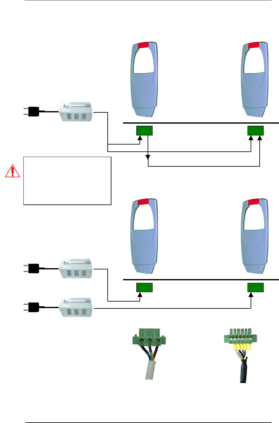
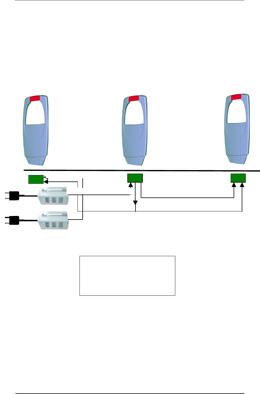
System Connections (Pro-Guard & Uni-Guard)
3-Pin Power Connector
6-Pin Inter-Connector
24V
24V Transformer
110/220vac
Single
Pro-Guard System
Rx/Tx Tx/Rx
3-Pin Power Connector 6-Pin Inter-Connector
24V
24V
24V Transformer
3-Pin Power Connector
110/220vac
24V Transformer
110/220vac
Two
Uni-Guard Systems
Uni-Guard #1 Uni-Guard #2
(No Inter-Connection)
Caution: One step-down
transformer can only
support one Uni-Guard.
Connecting two Uni-Guards
will cause the transformer
to overheat and damage it.
Pro-Guard & Uni-Guard Installation Manual
8
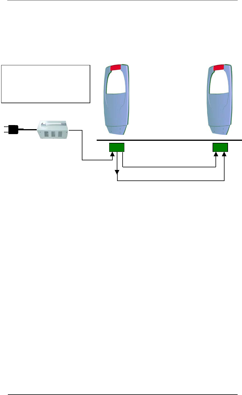
Optional Power Connection for Pro-Guard
There is another 3-pin connector (J5) on the bottom of the PC board. This provides a closer
and more convenient place to connect power from one of the closer pedestals instead of
connecting power directly to the transformer box.
3-Pin Power Connector
6-Pin Inter-Connector
24V
24V Transformer
110/220vac
Single
Pro-Guard System
Rx/Tx Tx/Rx
3-Pin Power Connector
Note: This type connection
cannot be done with multiple
Uni-Guards because one
transformer can supply power
to only one Uni-Guard.
Pro-Guard & Uni-Guard Installation Manual
9
Optional Split System Connection for Pro-Guard (two Tx’s & one Rx)
There is another split system configuration for Pro-Guard, two transmitters and one receiver.
Two interconnections are required to connect two 6-pole connectors from J3 and J12 (see
page 14) on the bottom PC board of the receiver to each transmitter. This provides a
convenient way for one Pro-Guard receiver to slave two transmitters. Please note that a
second transformer box is required. One transformer box can only power one standard
Pro-Guard system (Tx and Rx).
Tx Tx Rx
3-Pin Power Connector
3-Pin Power Connector
6-Pin Interconnector 6-Pin Interconnector
3-Pin Power Connector
24V Transformer
24V
24V
110/220vac
Note: This configuration requires
two transformer boxes because
one transformer box can supply
power to only one Pro-Guard
system (Tx/Rx).
Pro-Guard & Uni-Guard Installation Manual
10
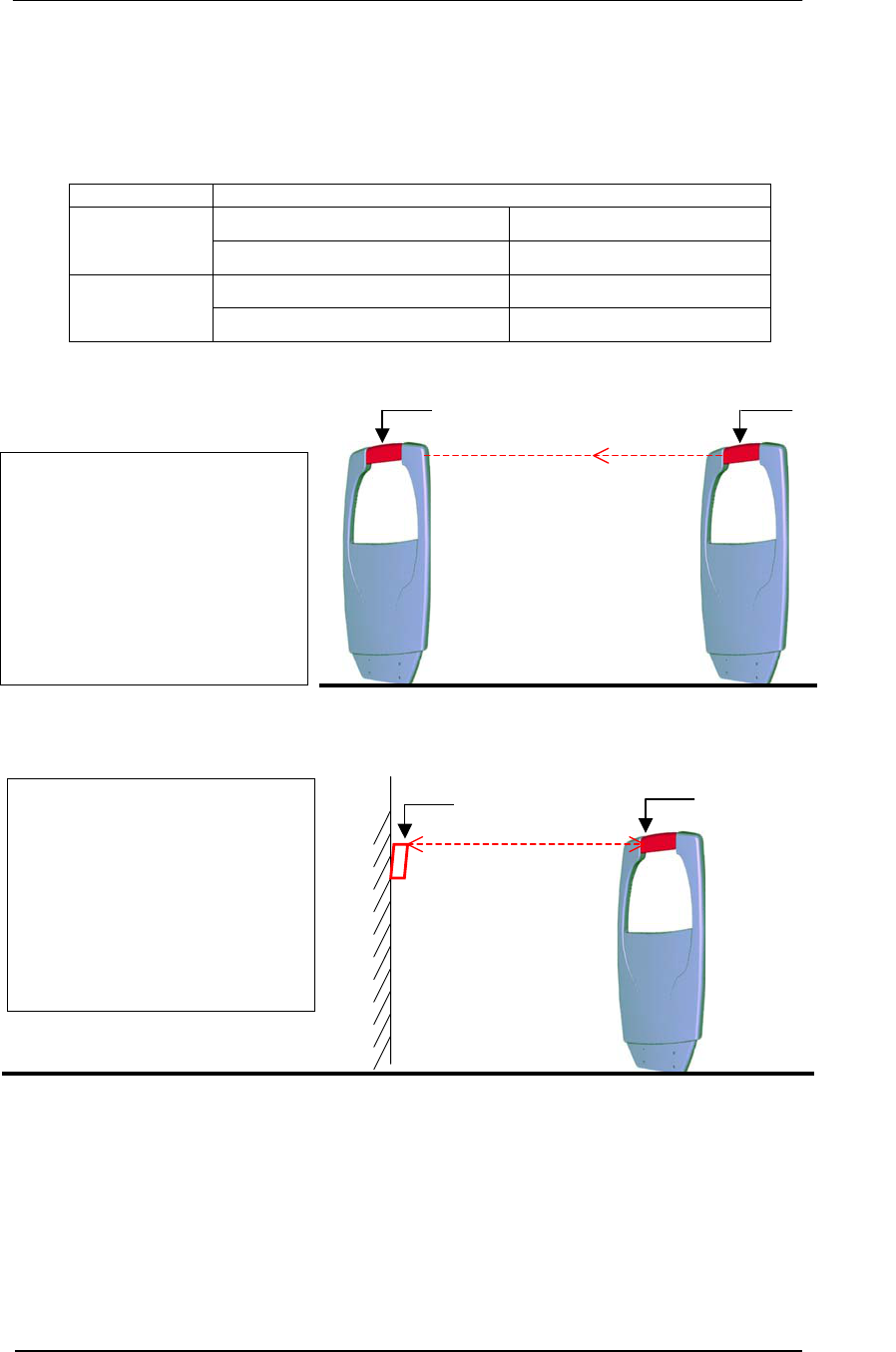
Optional IR Counting System Configuration (Pro-Guard & Uni-Guard)
There is an optional IR people counter feature available when the system is connected to
WG’s EASNetTM software. Follow the configuration setup described below for using this
feature.
System Configurations
Transmitter Pedestal Receiver Pedestal
Pro-Guard
Integrated IR Transmitter (1pc) Integrated IR Receiver (1pc)
Pedestal External Reflector
Uni-Guard
Integrated IR Transceiver (1pc) External IR Mirror (1pc)
Note:
This type of configuration only
has one IR monitor channel
between the pedestals. Please
arrange the transmitter and
receiver with IR modules face-
to-face, otherwise the IR
receiver will not be able to
receive signals from the
transmitter.
Pro-Guard Rx Pro-Guard Tx
Integrated
IR Receiver
Integrated
IR Transmitter
IR Monitoring channel
(One-way counting)
Uni-Guard
Integrated
IR Receiver
IR Mirror
IR Monitoring Channel
(One-way counting)
Note:
This type of configuration only
has one IR monitor channel on
one side of the pedestal.
Please arrange the integrated
transceiver and IR mirror face-
to-face, otherwise the IR mirror
will not be able to reflect the
signals back to the
transceiver.
Pro-Guard & Uni-Guard Installation Manual
11
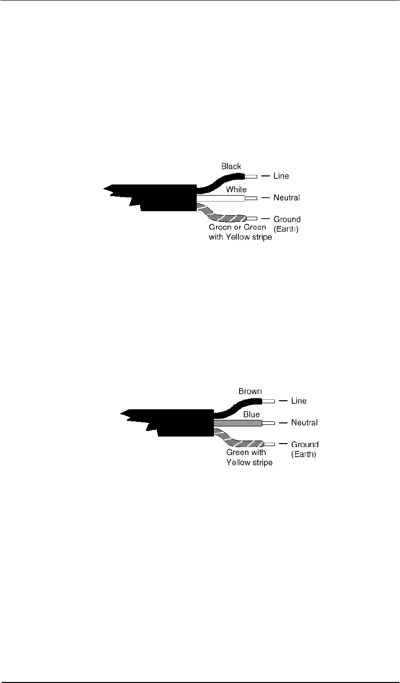
Power Cord Notices
North American Power Supply Cords
This equipment is supplied with an external power line at one end and a molded
receptacle terminal block at the other end. Conductors are color coded white
(neutral), black (line) and green or green/yellow (ground).
Operation of this equipment at voltages exceeding 130vac will require power supply
cords that comply with NEMA configurations.
International Power Supply Cord
This equipment is supplied with an external power line at one end and a molded
receptacle terminal block at the other end. Conductors are CEE color-coded—light
blue (neutral), brown (line) and green/yellow (ground). Other IEC 320 C-13 type
power supply cords can be used if they comply with the safety regulations of the
country in which they are installed.
We recommend that you use a CE approved power cord H05 VV-F or H05 VVH2-F2
(Refer to the electrical code which governs your country for installation of an Anti-Theft
Unit to the main power supply)
Pro-Guard & Uni-Guard Installation Manual
12
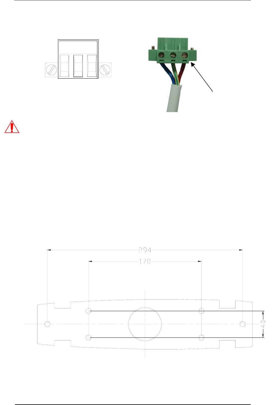
Pipe the power line to where the posts will be mounted. Attach the power cord to the field
connector by following the wiring instructions below.
IMPORTANT NOTICE:
1. Use a torque of 4.5Kg/cm to screw down the wires.
2. The L and N lines can be swapped, but keep all systems wired IDENTICALLY with
respect to the order of the three power lines.
3. If the Pro-Guard shuts down other manufacturers 58Khz deactivators or cause them
to false alarm, or other systems cause the Pro-Guard to shut down or false alarm,
perform the following action:
SWITCH THE “L” AND “N” TERMINAL POSITIONS OF THE POWER CORD AND
THEN TRY SYCHRON ADJUSTMENT (SEE APPENDIX ENTRY B)
4. We recommend using a power cord with a maximum length of 3 meters.
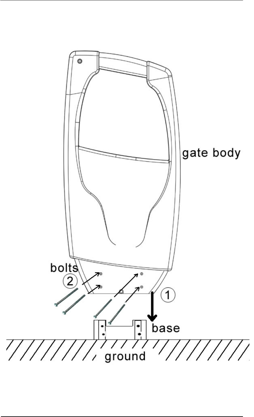
Dig six holes (10mm diameter, 40mm deep) for installing the base.
Black or Brown = Live
White or Blue = Neutral
Green & Yellow = Ground
L GND N
Screw Torque Specification:
4.5Kg/cm
Pro-Guard & Uni-Guard Installation Manual
13
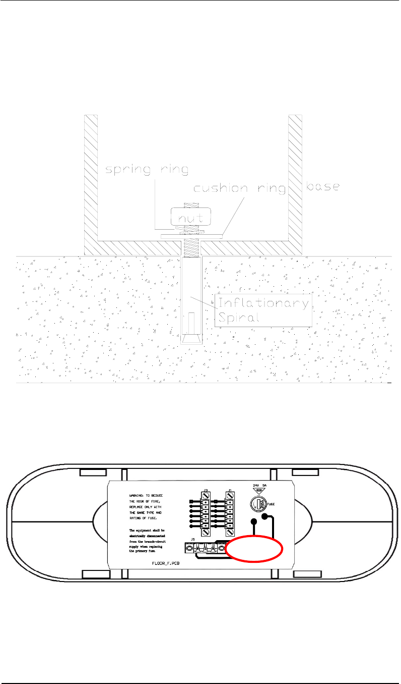
Insert the inflationary spirals into the holes.
Set the base in place, allowing the spiral heads to go through the holes in the base.
Place cushion rings, then spring rings and nuts on the spiral heads, and screw the nuts to fix
the base to the ground.
Lift the gate bottom and mount the 3-pin power line plug onto the power socket (J6) on the
bottom of the PC board as shown in the following picture (note red circle around the socket).
Pro-Guard Transmitter – Bottom View
Pro-Guard Transmitter – Bottom View
Pro-Guard & Uni-Guard Installation Manual
14
Pro-Guard Receiver – Bottom View
There is one external alarm switch J8 on the Pro-Guard receiver and Uni-Guard. The switch
is closed only when an alarm is triggered by the system. To connect the system to an external
alarm, first press down the yellow button, then insert the two ends of the external alarm wire
into each of the wire receptacle holes and release the yellow button. The wire will now be held
in place by the connector. The external alarm switch has a rating of 1A@250vac/24vdc.
Battery or Power
<1A@24vdc
J8
Alarm
Pro-Guard Receiver Bottom PCB
Notes:
1. Wire length to the dry contact circuit is limited to 20 feet.
2. To prevent high voltage noise from being introduced into
the Pro-Guard or Uni-Guard and degrading the system’s
performance, it is highly recommended that you use a
24vdc output relay.
Pro-Guard & Uni-Guard Installation Manual
15
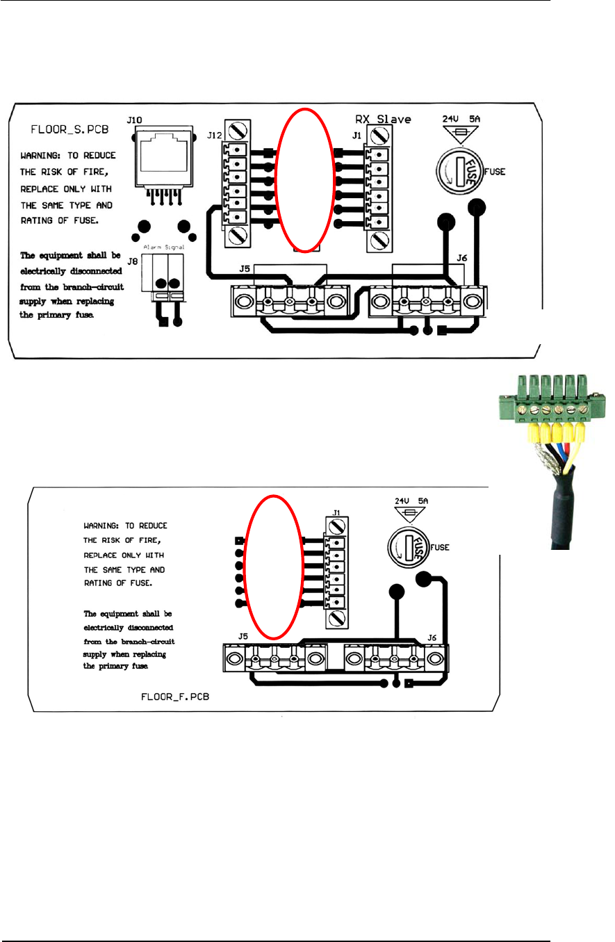
On Pro-Guard systems there is an interconnection between the receiver and transmitter.
Connect the Interconnection Line Plug onto socket J3 (6-pin connector) on the PC Board as
shown in the picture below (both transmitter and receiver, circled in red).
Pro-Guard Receiver – Bottom PCB
Pro-Guard Transmitter – Bottom PCB
Note: If this is a Pro-Guard installation using two Transmitters & one Receiver, use J3
and J12 to connect the two transmitters. Do not use the J1 (Rx Slave) port.
6-Pin Interconnection
Connector
Screw Torque
Specifications
1.7Kg/cm
Pro-Guard & Uni-Guard Installation Manual
16
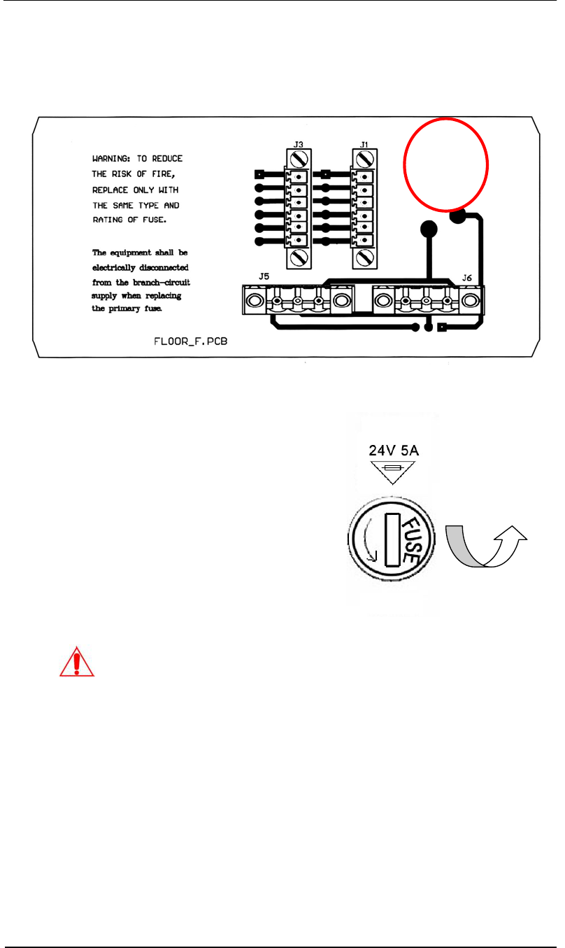
Fuse Replacement Information
The fuse holder is located at the bottom PC board in the pedestal.
1. Equipment shall be electrically
disconnected from the branch-
circuit supply when replacing the
fuse.
2. Remove the fuse holder with a
screwdriver, rotating it in a
counterclockwise direction.
3. Replace the fuse in accordance
with the specification noted
below.
Counterclockwise
Fuse Replacement:
Extended Fuse (Time-Delay Fuse)
5mm x 20mm 5A
WARNING
–
TO REDUCE THE RISK OF DAMAGE, REPLACE ONLY WITH
THE SAME FUSE TYPE AND RATING.
Pro-Guard & Uni-Guard Installation Manual
17
Insert the gate body slick into the base track and cover the whole base.
Insert the two bolts through the two tunnels at the lower part of the gate body.
Pro-Guard & Uni-Guard Installation Manual
18
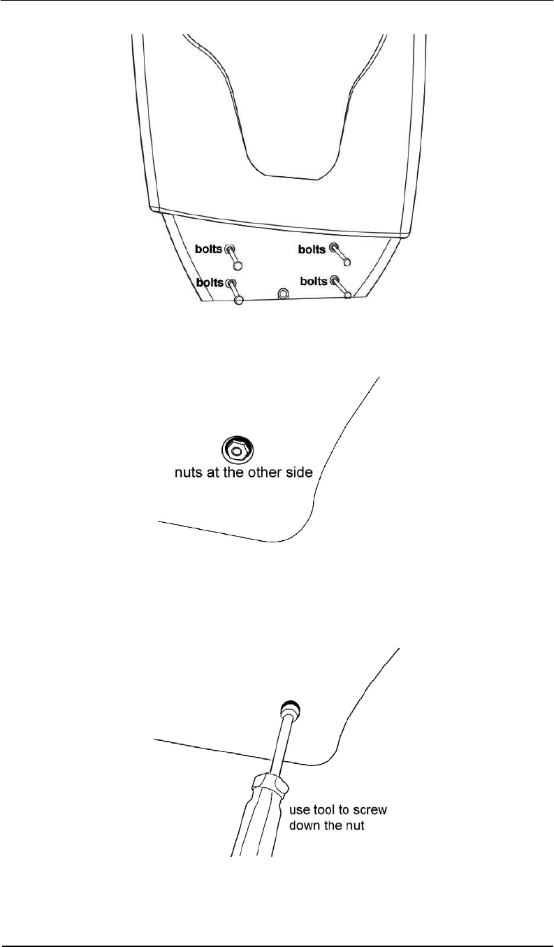
Insert the nuts into the bolt shafts from the other side.
Use the provided tool to screw down the nuts.
Pro-Guard & Uni-Guard Installation Manual
19
IR Control Keyboard Function Description & Default Parameters Table
Key ID Button Parameters Description Default Value Valid Range
A GN Gain Adjustment 1 0, 1
B SYN Sync Adjustment 1 0 to 250
C RE Receiving Window Delay 8 0 to 15
H1 Minimum signal adjustment for
antenna Channel 1
H2
MIN
Minimum signal adjustment for
antenna Channel 2
40
0 to 999
(Practical
range 0-200)
D NSE Noise Display (2 channels) 0 0 to 2
F TX OFF Turn off transmitter 1 0 to 1
E DFT Return to default settings 0 0 to 1
P PC Password change 689 (see note) 0 to 999
G ARM OFF Turn off alarm sound 1 0 to 1
L ARM RST Alarm count reset 0 0 to 1
S SA Save the parameters to Flash ROM 0 0-1
CON Confirm the parameters input NA NA
EX Exit NA NA
Note: Default password is 689. After changing, the system will use the new password
as default. The new password will remain saved at power off.
PC
PSW
1 2 3
4 5 6
7 8 9
0
CON TX
OFF
MIN1
DFT
MIN2
GN SYN
A
RM
OFF
RE NSE
A
RM
RST
SA EX
Pro-Guard & Uni-Guard Installation Manual
20
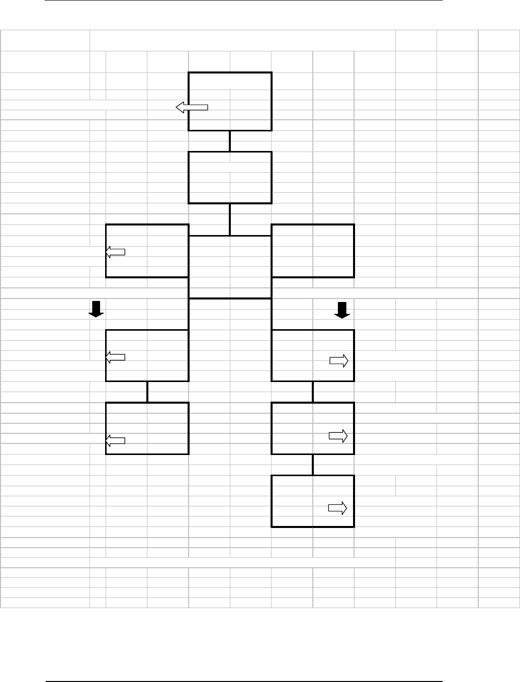
FLOW CHART OF SUGGESTED TUNING PROCEDURES
System Defaut
Weak Performance & or False alarms
from your systems or theirs
Chec k Nois e "D"
D B
Alternate betw een D1-D2 & B to
get most favorable parameters
( Low Noise Level )
If noise is less than 80 If noise is very high (eg. more than hundreds)
H A
If OK - You are done If noise is very high
1/2 of new noise or less=value than several hundred
inc rease s lightly if False A larms Adjust Gain to 0
IF Not Acceptable
Check Noise Value and
Sensitivity of the System .
C H If system is picking w ell,
Adjust until sensitive enough Your'e Done, If w eak
then increase until stable adjust H to approximately
1/2 of Noise Level, if f alse
alrarms adjust slightly
Upw ar d
C Adjust from C6 to C1
until system is w orking
w ell. Than adjust Up
until system is stable
*Alw ays Watch the system f or about an Hour to ensure that you have chosen stable paramaters
Pro-Guard & Uni-Guard Installation Manual
21
Tuning Procedures & Tips
There are mainly two problems that affect system’s functioning and
performance. One is that system picks up tags and labels poorly. The other is
that system false alarms (or causes other system to do so) without tags or
labels in detection zone.
Low Pick up Rate
1. Check noise “D” (ranging from 0-
999, >400 or so is heavy noise).
2. Adjust MIN, GN, RE, (see diagram
below).
3. Shorten pedestal separation.
Interference with or by othe
r
systems
1. Swap L & N terminals on power plug.
2. Adjust SYN “B” step by step.
Please open and tune the systems one by one if there are multiple pedestals
working together. It will help determine which system is causing the problem.
200
RE
Default 8
GN
MIN
Default 40
But Tendency to
False Alarm
Shorter detection range
But lead to stability
0
0 15
0
Decrease Sensitivity Increase Sensitivity
Default 1
PROBLEMS
SOLUTIONS
The diagram below explains how the major three tuning parameters influence
system performance.
MIN is the most important.
Pro-Guard & Uni-Guard Installation Manual
22
Remote Control Programming
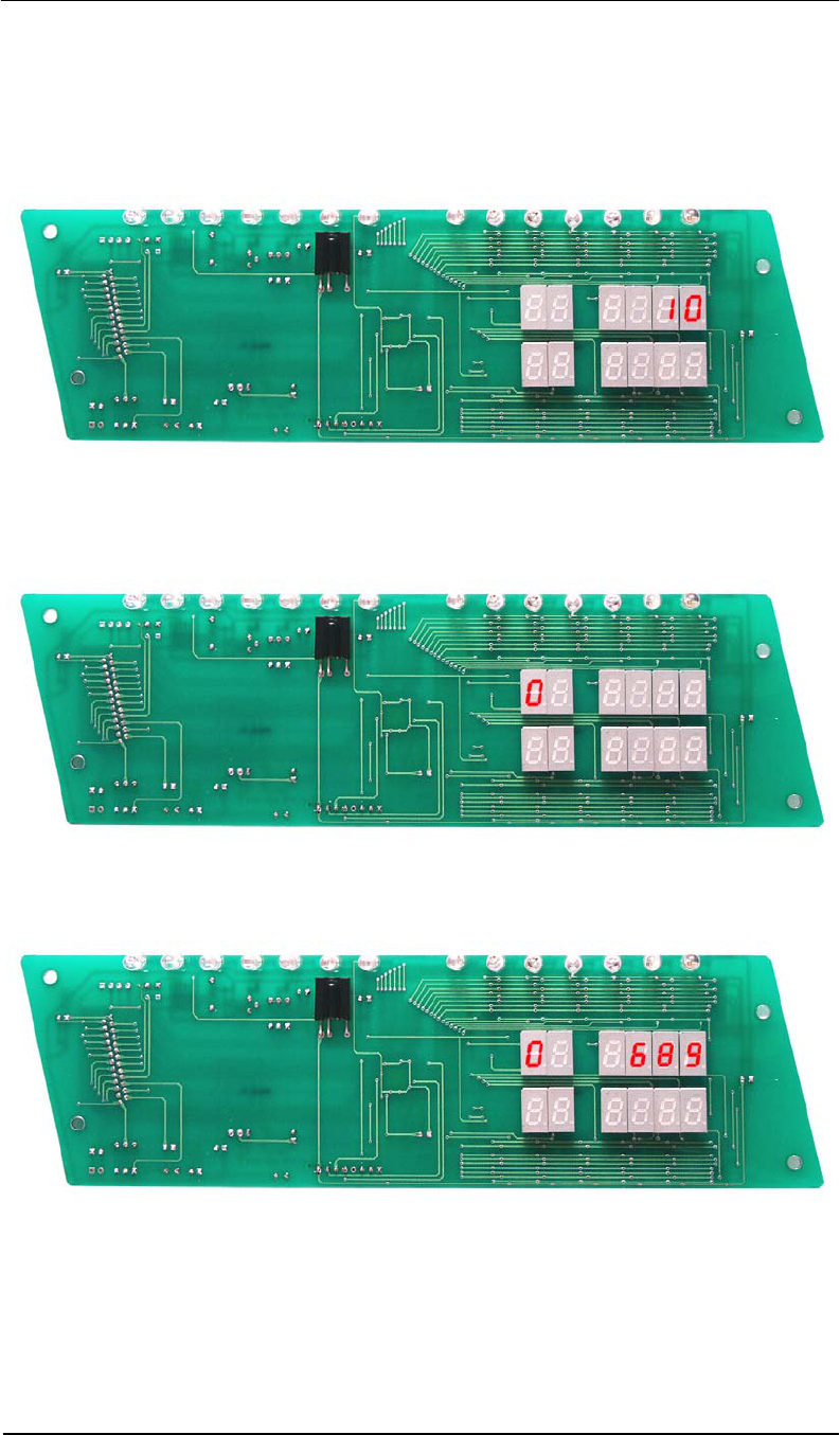
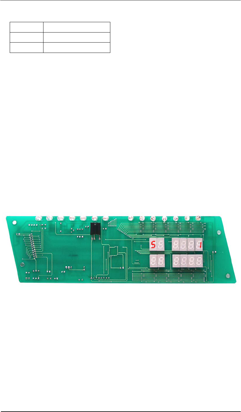
Without receiving remote control signals, the panel displays the alarm count, indicating the
number of times the system has alarmed. See Figure 1.
Figure 1. Alarm Count
Press [PSW] button to open the remote control, then enter the password. The default
password, if not previously changed, is 689.
Figure 2. Display after [PSW] is Pressed
Input Password 689 and press [CON] to confirm/accept the password.
Note: Inputting the wrong password will cause an error message to be displayed as
per the following picture. After three successive times of inputting an incorrect
password, the remote will be disabled. You will need to turn system power off/on and
input the password again.
Pro-Guard & Uni-Guard Installation Manual
23
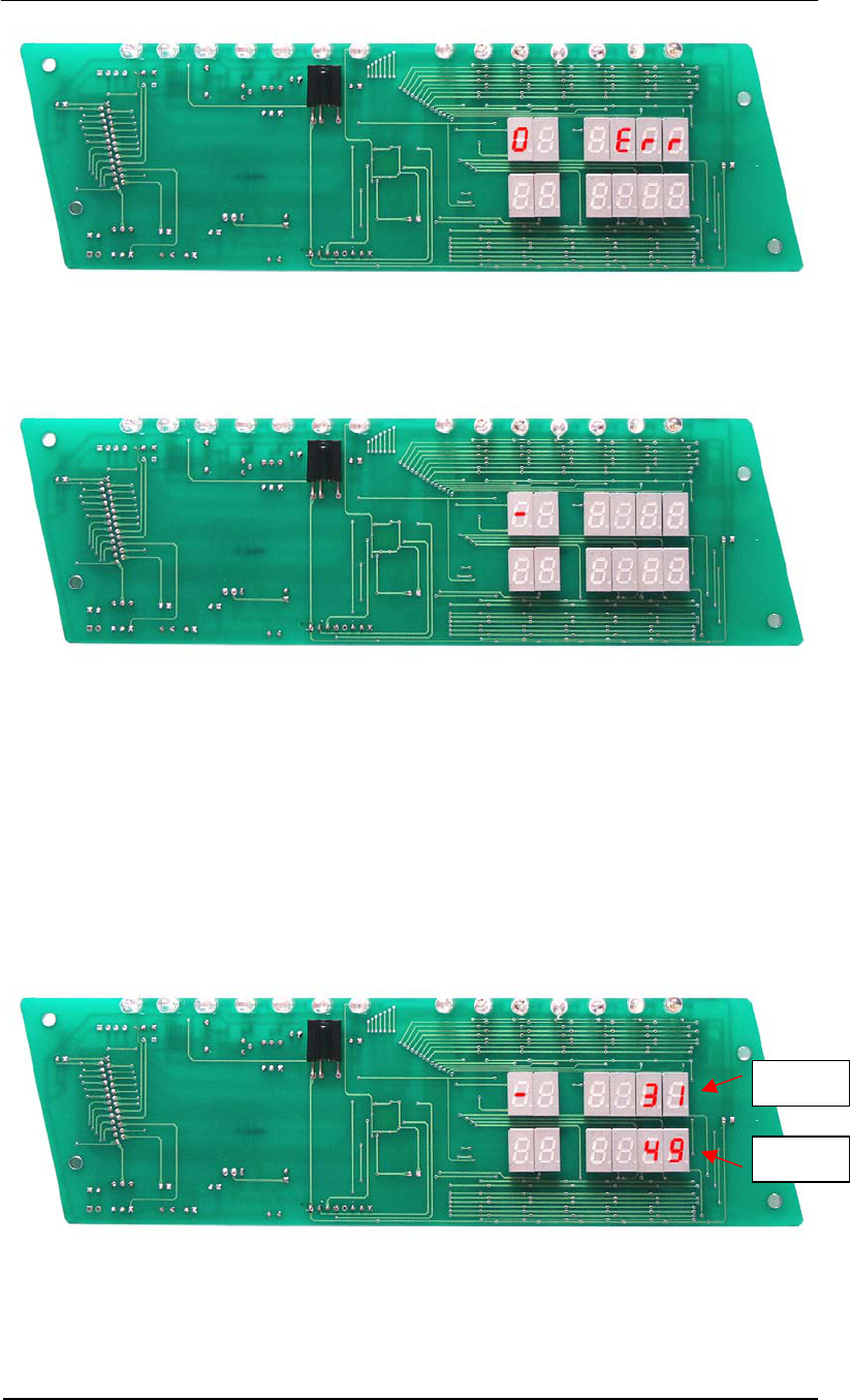
When the correct password is verified, the panel will display the following and is now ready for
receiving configuration inputs.
There are three basic steps to inputting a programming parameter:
• Press function button.
• Input parameter number.
• Press [CON] to accept the parameter.
After parameter confirmation, the panel will display the tag window signal. If there is no tag in
the detection zone, the value reflects the noise level in the receiving window without a tag.
The upper value reflects the signal level in the tag window from antenna channel 1. The lower
value reflects the signal level in the tag window from antenna channel 2. (See NSE noise
display entry; it’s the same value with D1)
CH 1
CH 2
Pro-Guard & Uni-Guard Installation Manual
24
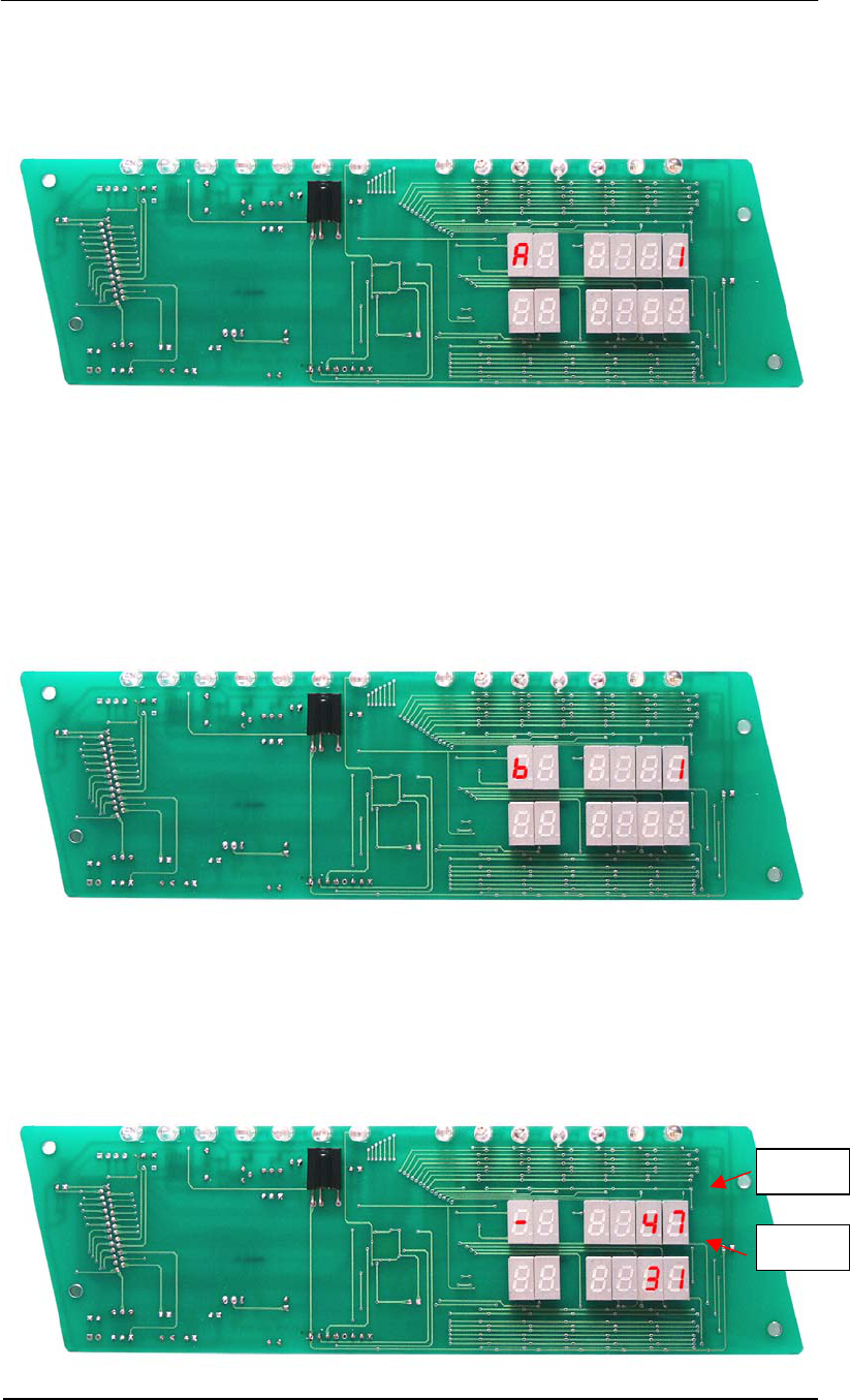
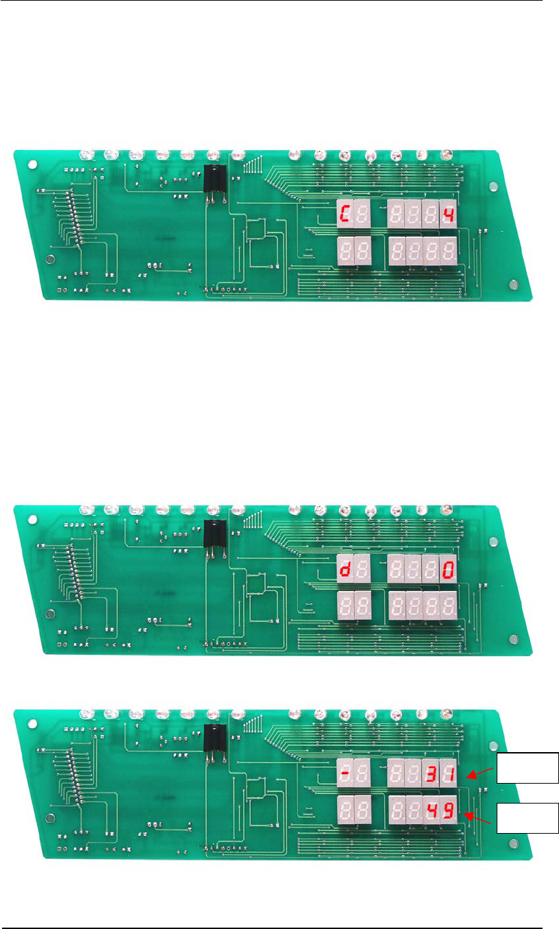
Key ID A: Gain Adjustment (Range: 0-1)
• Press [GN] – panel displays as per Figure 3.
• Input parameter number.
• Press [CON] to accept the parameter.
Figure 3.
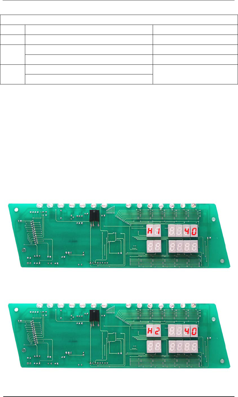
Key ID B: Sync Adjustment (Range: 0-250; increment: 1)
This sets the time from zero crossing point to the start point of transmitting burst. It is
important to eliminate crosstalk between different systems. Setting the default value to b-1 will
in most cases not interfere with other AM products.
• Press [SYN] – panel displays as per Figure 4.1.
• Input parameter number.
• Press [CON] to view the nose conditions. Display will be as per Figure 4.2.
Figure 4.1
Under this entry, you can also see the different noise condition (from the light segment display
and number indicator) at a different phase when the adjustment is applied. It will help you
select a relatively “clean” phase environment for the system.
CH 1
CH 2
Pro-Guard & Uni-Guard Installation Manual
25
Key ID C: Receiving Window Delay (Range: 0-15; increment: 1)
You can input a number from 1-15. The larger the number, the later the receiving window will
be opened.
• Press [RE] – panel displays as per Figure 5.
• Input the parameter number.
• Press [CON] to accept the parameter.
Figure 5.
Key ID D: Noise Condition Display (Range: 0-2)
The LEDs indicate the signal level by value figures. The upper value reflects the nose level
from antenna channel 1; the lower value reflects the noise level from antenna channel 2.
Note: If the noise condition display is open, the alarm will be deactivated unless you
input 0 to shut down the display.
• Press [NSE] – panel displays as per Figure 6.1.
• Input the parameter number.
• Press [CON] to accept the parameter – panel displays as per Figure 6.2.
Figure 6.1
Figure 6.2
CH 1
CH 2
Pro-Guard & Uni-Guard Installation Manual
26
Noise Condition Display Configuration Table
Value Function Description Detection Purpose
0 Shut down tag or noise window display.
Tag window display for channel one. Detect tag entering vertically.
D1
Tag window display for channel two. Detect tag entering horizontally.
Average noise window display for channel one.
D2
Average noise window display for channel two.
Monitor average noise.
Note: The average noise level is also weighted by the Minimum Signal Adjustment
value. The D2 value will show the maximum value between average noise and MIN
value.
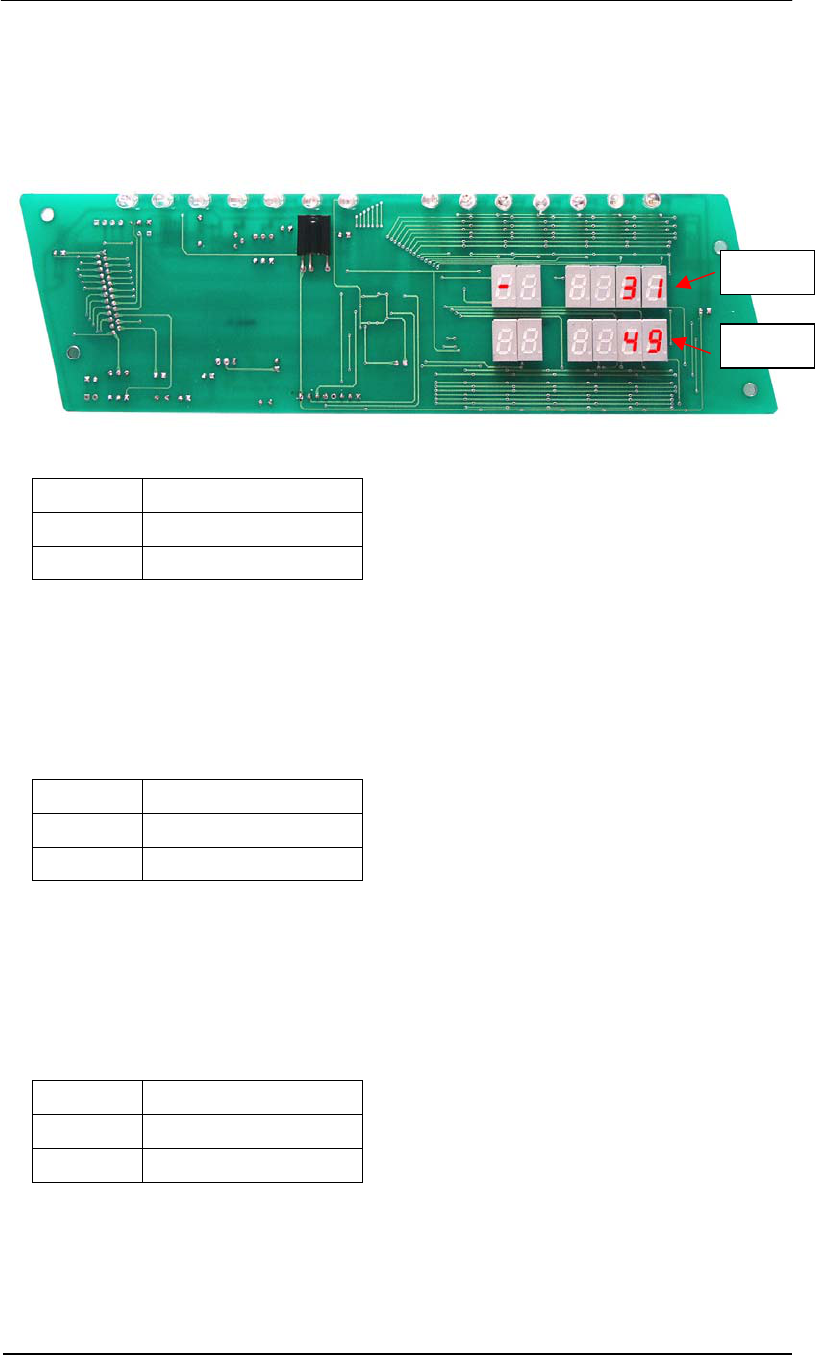
Key ID H: Minimum signal Adjustment (Suggested increment: 20; practical range: 0-200)
Decreasing this number will increase system sensitivity but also at the risk of false alarming.
Vice versa, increasing the value will lower system sensitivity to avoid false alarms caused by
uncontrollable environment noise.
There are two antenna channels. Channel 1 is related to vertical orientation and Channel 2 is
related to horizontal orientation. H1 sets the minimum signal of Channel 1, and H2 sets the
minimum signal of Channel 2.
• Press [MIN] – panel displays as per Figure 7.
• Input the parameter number.
• Press [CON] to accept the parameter.
Figure 7.1. Antenna Channel 1
Figure 7.2. Antenna Channel 2
Pro-Guard & Uni-Guard Installation Manual
27
After confirmation of H1 or H2 values, the panel will display the average noise level weighted
by the minimum signal adjustment for both antenna channels as follows. (See NSE noise
display entry. It’s the same value with D2)
The upper value reflects the average noise level weighted by H1 in antenna channel 1. The
lower value reflects the average noise value weighted by H2 in antenna channel 2.
Key ID F: TX Off (Default value: 1; valid range: 0-1)
Value Action
0 Turn off Tx
1 Turn on Tx
• Press [TX OFF]
• Input the parameter number.
• Press [CON] to accept the parameter.
Input 0 will turn down the transmitting burst via software control. If system power is reapplied,
the system will return to default state of 1.
Key ID G: Alarm Sound Off (Default value: 1; valid range: 0-1)
Value Action
0 Turn off alarm sound.
1 Turn on alarm sound.
• Press [ARM OFF]
• Input the parameter number.
• Press [CON] to accept the parameter.
Input 0 will turn down the alarm sound via software control. If system power is reapplied, the
system will return to default state of 1.
Key ID L: Alarm Count Reset (Default value: 0; valid range: 0-1)
Value Action
0 Initial state.
1 Reset alarm count.
• Press [ARM OFF]
• Input the parameter number.
• Press [CON] to accept the parameter.
Input 1 will reset the alarm count to 0.
CH 1
CH 2
Pro-Guard & Uni-Guard Installation Manual
28
Key ID E: Load Default Settings (Default value: 0; valid range: 0-1)
Value Action
0 Initial state.
1 Load default settings.
Input 1 will load default settings. See Default Parameters Table.
Key ID P: Password Change (Default value: 689; valid range: 0-999)
You can input customer-defined passwords with this entry. Press [CON] button after inputting
to activate the new password.
Note: Please SAFEGUARD the new password if you have changed from the default.
Once the new password is activated, the system will no longer recognize the 689
default password.
Key ID EX: Exit
Press [EX] to return to the alarm counter display status.
Key ID SA: Save
This button will save all current parameters to flash ROM and are saved, even after power
shutdown. When the system is rebooted, it will load all previously saved parameters from
flash ROM.
• Press [SA] – panel displays as per Figure 8.
• Input 1
• Press [CON] to accept the current parameters.
Figure 8.
***