WG security WGFP58 Proximity Deactivator User Manual Manual Fastpad 010704C
WG Security Products, Inc Proximity Deactivator Manual Fastpad 010704C
UserManual.wiki
>
WG security
>
WGFP58 User Manual
User Manual
Navigation menu
Upload a User Manual
Namespaces
Wiki Guide
HTML
PDF
Info
Views
User Manual
Discussion / Help
Navigation

![14 Recorded Media Products Deactivation Instructions: 1. Access to Programming Mode • Press [PSW] • Input password (default is 68 unless previously changed). • Press [CON] to enter programming mode. 2. Set TX OFF to enable low power deactivation mode • Press [Tx OFF] • Input 1 to enable low power deactivation. • Press [CON] to accept the parameter. 3. Save to control box Flash ROM • Press [SA] • Input 1. • Press [CON] to accept the parameter. • Press [EX] to exit programming mode. Low Power Deactivation is strongly recommended formagnetic media products such as pre-recorded audiotapes, video tapes, floppy disks, etc. Use the remotecontrol to set FastPad to low power deactivation mode. Deactivation Range Change! When setting FastPad to low power deactivation mode formedia products deactivation, the active distance fordeactivation is shortened accordingly. You must now placethe label closer to deactivation antenna surface to ensurecomplete deactivation. DR labels Vertical Detection 4cm (1.5 in) Horizontal 2cm (1 in)](https://usermanual.wiki/WG-security/WGFP58/User-Guide-408479-Page-17.png)
![15 LED Error Indicators Description LED Definitions • L4 (Yellow) = Program Running Indicator • L3 (Green) = Over-voltage Detection (115±10%Vac, 60Hz and 230±10%Vac, 50Hz) • L2 (Red) = Overheat Detection • L1 (Blue) = Continuous 100 times Operation Counting Error Types Note: If any of following errors occurs, the corresponding LED will turn on and FastPad will lock up. Turn the power switch off/on to reset the unit. • [Red] = Deactivating coils have overheated. Allow the unit to cool down and reapply power. • [Green] = Over-voltage detection of the power source (10% tolerance: 115±10%Vac@60Hz and 230±10%Vac@50Hz). Remove power until the power source is brought within required limits. • [Red] and [Yellow] = 100 times continuous deactivation count has been reached. In order to prevent system overheating, allow the system to cool down and reapply the power. • [All LEDs On] = Deactivator coils current has exceeded the limit. Reapply power to the unit. FAST PADCONTROL BOXTMLANREMOTE CONTROLL1L2L3L4 CONTROL BOX - FRONT VIEW LED Error Indicators](https://usermanual.wiki/WG-security/WGFP58/User-Guide-408479-Page-18.png)
![19 Press [PSW] button to activate the remote control, and then enter the password (factory default is 68). Input the number 68 (or the new password if you have changed it). Press [CON] to instruct the Control Box to accept the password. Note: Entering the wrong password input will disable the panel from further instructions. Exit and re-press PSW to enter the correct password (see the picture below). After THREE successive attempts with the wrong password the remote control will be completely disabled. At this point you must turn the unit on/off and begin again. LAN REMOTE CONTROL 0 LAN REMOTE CONTROL8 0 6 LAN REMOTE CONTROLr E r](https://usermanual.wiki/WG-security/WGFP58/User-Guide-408479-Page-22.png)
![20 When the correct password is verified, the LEDs will display as per the following picture and wait for configuration type input. Key ID “B” - Sync Adjustment (range: 0-99; increment: 1) This adjustment sets the time from zero crossing point to the start point of burst transmission. It is used for eliminating cross talk between different systems. In most cases the default b-1 value will achieve system stability with respect to other AM products. Press [SYN] and the LEDs will display as shown below. Input the number for the parameter. Press [CON] to see the noise conditions. Note: The adjustable range is 0-99 (0 – 3.366ms), with each increment equaling 34µs. (34µs x 99 total increments = 3366µs = 3.366ms) LAN REMOTE CONTROL - LAN REMOTE CONTROL1 b](https://usermanual.wiki/WG-security/WGFP58/User-Guide-408479-Page-23.png)
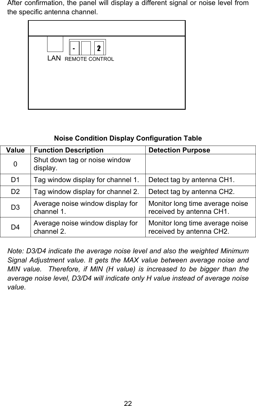
![21 Under this mode, you can also see the different noise condition at a different phase. If there is a phase problem, other AM systems’ burst transmission will interfere with FastPad’s receiver, and you will see a large noise indication in D1, D2. Key ID “D” - Noise Condition Display (Valid parameters: 1,2,3,4 - see configuration table below) The LEDs display the signal level number, with a level range from 0-8. Note: When in the noise condition display mode, the alarm will be deactivated until you exit this mode. Press [NSE] and the LEDs will display as shown below. Input a number for the parameter. Press [CON] to accept the parameter. LAN REMOTE CONTROL7 - LAN REMOTE CONTROL0 d](https://usermanual.wiki/WG-security/WGFP58/User-Guide-408479-Page-24.png)
![23 Key ID “H” - Minimum Signal Adjustment (valid range: 0-8, increment 1) Lowering this number will increase the label detection sensitivity of the FastPad, but will also increase the risk of false deactivation. Vice versa, raising it will decrease the sensitivity or detection range to adapt to deactivation range. While there are two antenna channels, FastPad has only one H value adjustment, and it will apply to both of the antenna channels for minimum signal adjustment. Press [MIN]. The LEDs will display as shown as below Input number for the parameter. Press [CON] to accept the parameter. Key ID “E” – Load Default Settings (default value: 0; valid range: 0-1) Value Action 0 Initial state, no meaning 1 Load default settings Input value 1 will load the default settings (refer to the Default Parameters Table on page 10). LAN REMOTE CONTROL0 H](https://usermanual.wiki/WG-security/WGFP58/User-Guide-408479-Page-26.png)
![24 Key ID “F” – Low Power Deactivation Settings (default value: 0; valid range: 0-1) Value Action 0 Normal deactivation strength 1 Low power deactivation for media products Press [Tx OFF] Input number for the parameter. Press [CON] to accept the parameter. (Inputting “1” will lower the deactivation power for magnetic media products) Key ID “L” – Alarm Count Reset (default value: 0; valid range: 0-1) Value Action 0 Initial state, no meaning 1 Reset alarm count Press [ARM RST] Input number for the parameter. Press [CON] to accept the parameter. (Inputting “1” will reset alarm count to 0) Key ID “P” - Password Change (default value: 68; valid range: 0-99) The password can be changed in this mode from the factory default to your choice. Press the confirm button after input to activate the password. Note: If you change from the default password, save the new one in a safe place because if you forget it there will be no way to access the unit. Low Power Deactivation is strongly recommended for magnetic media products such as pre-recorded audio tapes, video tapes, floppy disks, etc.](https://usermanual.wiki/WG-security/WGFP58/User-Guide-408479-Page-27.png)
![25 Exit button Press [Exit] to return to Alarm counter display status. Save button This button will save all current parameters to Flash ROM, so when power is shut down the parameters will be saved. Next time the system reboots it will load all the parameters from Flash ROM. Press [Save]. The LEDs will display as shown below. Input 1 Press [CON] to accept the current parameters. *** LAN REMOTE CONTROL1 S](https://usermanual.wiki/WG-security/WGFP58/User-Guide-408479-Page-28.png)