WG security WGFP58 Proximity Deactivator User Manual Manual Fastpad 010704C
WG Security Products, Inc Proximity Deactivator Manual Fastpad 010704C
User Manual

58kHz FastPadTM II
Deactivator
Installation Manual
Version: 2003 Sep
Manual Part number: WG-FP-IM
(092403B)
WG SECURITY PRODUCTS INC.
3031 Tisch Way, Suite 602, San Jose, CA 95128 (USA)
Tel: 408-241-8000 ▪ Fax: 408-241-8082
For technical support in your country, visit our web site at www.wgspi.com.

WARRANTY DISCLAIMER
WG Security Product Inc. makes no representation o
r
warranty with respect to the contents hereof and
specifically disclaims any implied warranties o
f
merchantability or fitness for any particular purpose.
Further, WG Security Product Inc. reserves the right to
revise this publication and make changes from time to
time in the content hereof without obligation of WG
Security Product Inc. to notify any person of such
revision or changes.
TABLE OF CONTENTS
OVERVIEW....................................................................................................... 1
SYSTEM DESCRIPTION ..................................................................................... 1
FEATURES....................................................................................................... 1
SPECIFICATIONS .............................................................................................. 2
BEFORE-INSTALLATION GUIDE................................................................... 3
CAD DIMENSIONS ........................................................................................... 3
FLUSH MOUNT CUT OUT SUGGESTION ............................................................. 6
INSTALLATION SITE POWER SUPPLY CHECK ...................................................... 7
INSTALLATION................................................................................................ 8
PARTS LIST ..................................................................................................... 8
DEACTIVATOR COMPONENTS AND CONNECTIONS ............................................ 10
POWER CORD NOTICES ................................................................................. 11
FUSE REPLACEMENT ...................................................................................... 12
QUICK START INSTRUCTIONS ................................................................... 13
GENERAL SETUP AND USE ............................................................................. 13
RECORDED MEDIA PRODUCTS DEACTIVATION ................................................. 14
LED ERROR INDICATORS DESCRIPTION .......................................................... 15
IR REMOTE CONTROL KEYPAD DESCRIPTION ....................................... 16
TUNING PROCEDURES & TIPS................................................................... 17
REMOTE CONTROL PROGRAMMING ........................................................ 18
1
OVERVIEW
System Description
FastPad is a distance deactivator providing excellent deactivation reliability and high
throughput. The FastPad can be easily installed on the counter top or flush mount with
our mounting tray. FastPad deactivates labels up to 10 cm (4 in.) above the surface of
the pad at a high throughput speed.
Features
Proximity Deactivation
The FastPad offers distance deactivation, making it perfect for both source
tagged and retailer tagged merchandise.
Compact Size
The compact size of the deactivation antenna allows FastPad to easily be
integrated into a counter application.
Integrated Audible and Visual Notification.
Label deactivation notification is built into the FastPad.
LAN Accessible
FastPad includes the remote access capability via WG’s optional EAS NetTM
software for a variety of remote controls and data mining.
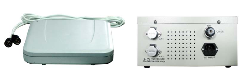
FastPad Antenna FastPad Control Box
2
Specifications
Electrical
Primary Input...................115±10%Vac, 60Hz
230±10%Vac, 50Hz
Rated Current .................5A
Ac Operating Phase...........0°, 120°, or 240°
Transmitter Output .........1.6ms burst
Transmitter Current.........3A peak (nominal)
Operating Frequency .....58kHz
Mechanical
FastPad Antenna
Length ............................295mm (11.6")
Width ...............................280mm (11")
Depth...............................54mm (2.1") (Include bottom feet)
Weight .............................4.5kg (10 lbs)
FastPad Control Box
Length ............................275mm (10.8")
Width ...............................190mm (7.5")
Depth...............................140mm (5.5") (Include rubber feet)
Weight .............................3kg (6.6 lbs)
FastPad Mounting Tray
Length ............................322mm (12.7")
Width ...............................307mm (12")
Depth...............................57mm (2.2")
Weight .............................0.4kg (1 lbs)
Environmental
Operating Temperature...0 to 30°C (32°–86°F)
Relative Humidity: ..........0 to 85% non-condensing
3
BEFORE-INSTALLATION GUIDE
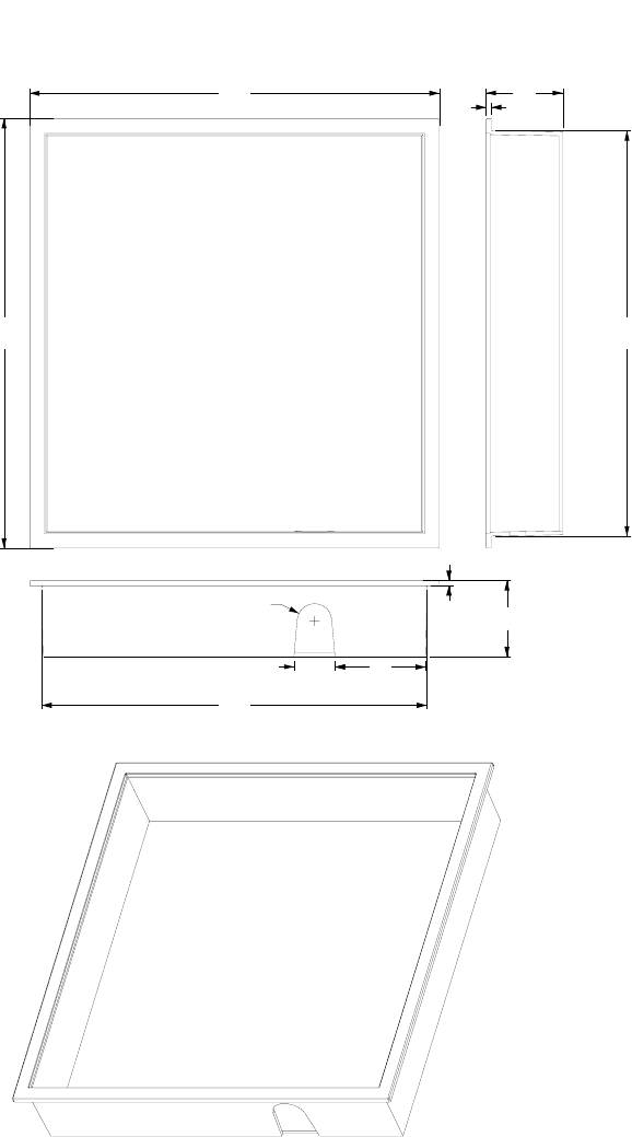
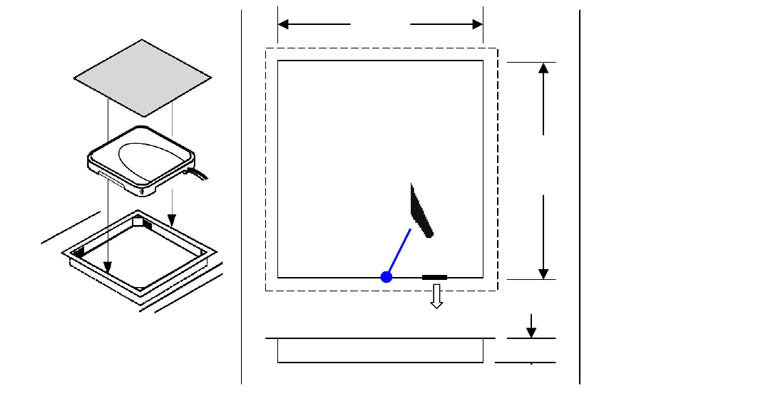
CAD Dimensions
4
288
R13
68
31
303
4
57
57
307
322
Flush Mount Tray
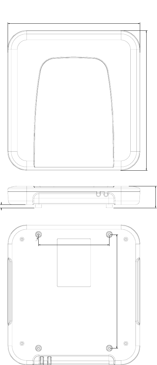
4
280
295
240.0
150.0
R6.7
6.5
54
FastPad Antenna
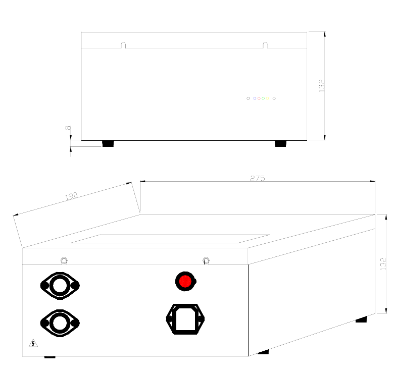
5
FAST PAD
CONTROL BOX
TM
AN2-HIGH VOLTAGE !
HANDLE WITH CARE
AN2
AN1 ON
AC INPUT
OFF
POWER
FastPad Control Box
6
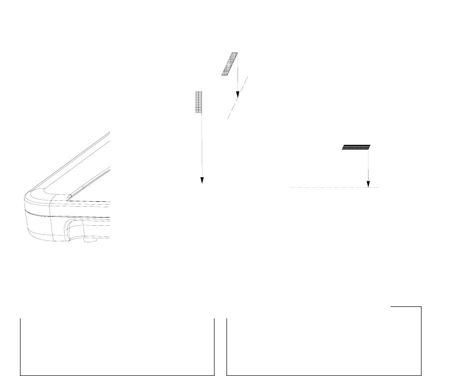
Flush Mount Cut Out Suggestion
304mm
(
12”
)
289mm
(
11.5”
)
Cut
57mm 2.2”
Cable Outlet
3cm free space around pad
for ventilation.
Antenna pad to control box
2.5m, 8.2 ft
Control box to AC
1.8m, 6 ft
Flange:
307 x 322 mm
12.1x 12.7in
7
Installation Site Power Supply Check
IT’S RECOMMENDED TO HAVE ALL FASTPADS ON THE SAME
POWER PHASE,otherwise you need to adjust B sync value step by step
to find a best position to sync different FastPads connected to power
source with difference phase.
IT’S RECOMMENDED TO HAVE ENOUGH CURRENT SUPPLY FOR
FASTPADS IF THERE ARE MULTIPLE FASTPADS SHARE ONE
POWER SUPPLY. The rated current for FastPad is 5A but the suggested
current draw for one FastPad is 7-8A for better performance, so a 15 amp
power box will better serve 2 FastPads instead of 3 or more.
IT’S RECOMMENDED TO HAVE GOOD GROUNDING FOR POWER
SUPPLY OF FASTPAD. (Some time the poor grounding and high noise
from power supply will decrease the sensitivity or detection range, check
Noise entry D1 and D2, a value over 6-7 will be considered as big noise)
8
INSTALLATION
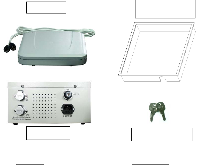
Parts List
Part Name Order Number
FastPad for 110VAC power voltage
Antenna
Control Box
FastPad for 220VAC power voltage
Antenna
Control Box
FastPad Flush Mounting Tray
FastPad Lock Key
WG FP-1
WG FP-AT-1
WG FP-CB-1
WG FP-2
WG FP-AT-2
WG FP-CB-2
WG FP-FMT
WG-FP-KEY
Control box (1)
Mounting tray (1)
for Flush Mountin
g
Antenna (1)
FastPad Lock Key (1)
9
FAST PAD
CONTROL BOX
TM
LAN
Remote Control Interface
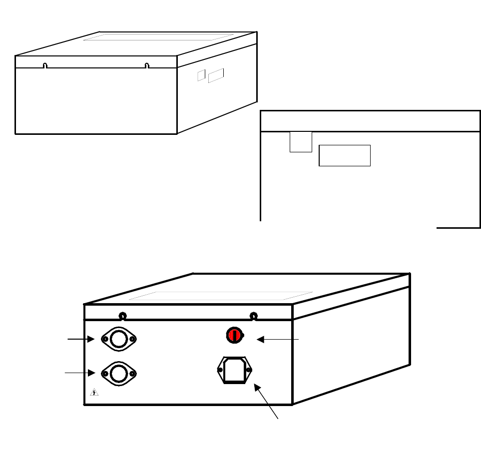
CONTROL BOX FRONT VIEW
CONTROL BOX SIDE VIEW
Remote Control Interface
LAN
POWER
AN2-HIGH VOLTAGE !
CARE IN OPERATION
AN2
AN1
AC INPUT
ON
OFF
Antenna
Socket #1
Antenna
Socket #2
Power Socket
CONTROL BOX BACK VIEW
Power Switch with Lock
10
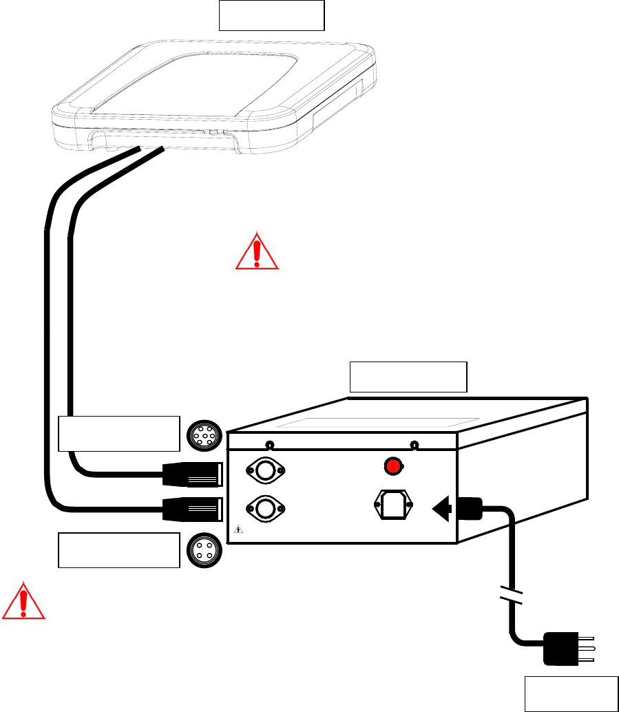
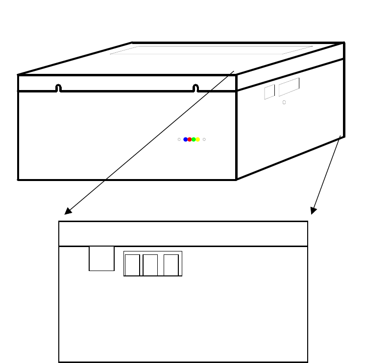
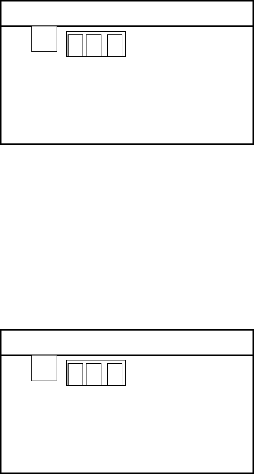
Deactivator Components and Connections
As shown in Figure 1, the deactivator consists of a detect/deactivator antenna
pad, power and control box. The cables used and connections are shown in
the following diagram. The antenna pad can be installed flush to the counter
with the flush mount kit.
POWER
AN2-HIGH VOLTAGE !
CARE IN OPERATION
AN2
AN1
AC INPUT
ON
OFF
7-pin Connector
4-pin Connector
Power Plug
Always match the antenna type (read the label on
the plastic housing) with control box input voltage
type before connecting them; make sure they are
matched.
An 110VAC antenna cannot be connected to a
220VAC control box, nor vice versa.
Antenna
Control Box
A
n 1
A
n 2
HIGH VOLTAGE – HANDLE WITH CARE!
Equipment must be electrically disconnected from
the branch-circuit supply when connecting the
antenna with the control box.
11
Power Cord Notices
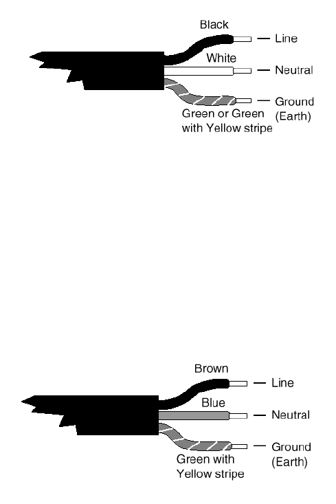
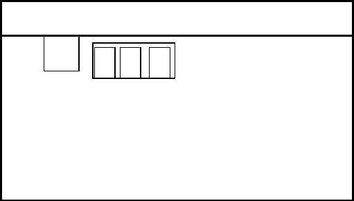
North American Power Supply Cords
This equipment is supplied with an external power line at one end and
a molded receptacle terminal block at the other end. Conductors are
color coded white (neutral), black (line) and green or green/yellow
(ground).
Operation of this equipment at voltages exceeding 130 vac will require
power supply cords that comply with NEMA configurations.
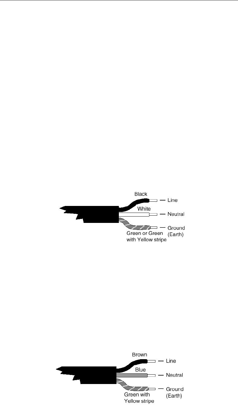
International Power Supply Cord
This equipment is supplied with an external power line at one end and
a molded receptacle terminal block at the other end. Conductors are
CEE color-coded—light blue (neutral), brown (line) and green/yellow
(ground). Other IEC 320 C-13 type power supply cords can be used if
they comply with the safety regulations of the country in which they are
installed.
We recommend that you use a CE approved power cord H05 VV-F or H05
VVH2-F2 (Refer to the Electrical code which governs your country for
installation of an Anti-Theft Unit to the Main power Supply)
12
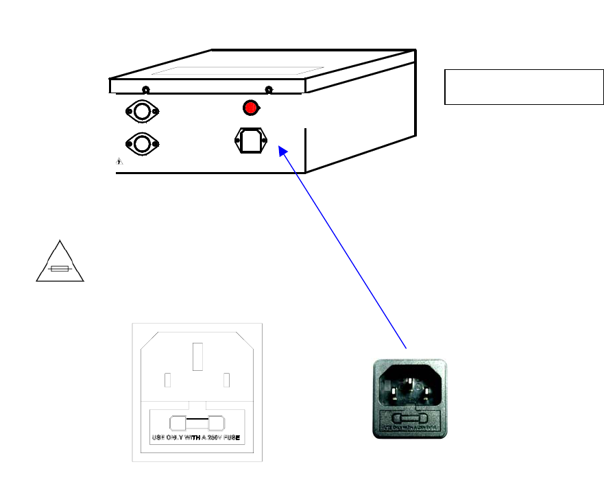
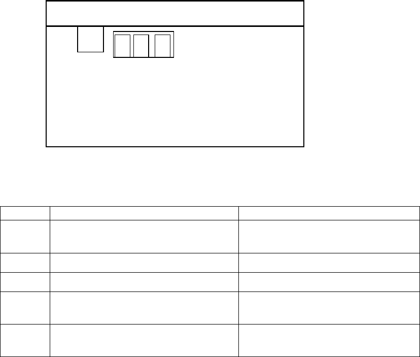
Fuse replacement
Equipment shall be electrically disconnected from the branch-circuit
supply when replacing the fuse.
WARNING – TO REDUCE THE RISK OF DAMAGE. REPLACE ONLY WITH
SAME TYPE AND RATING OF FUSE.
Fuse replacement
Extend fuse (time-delay fuse)
5mmx20mm 6.3A
POWER
AN2-HIGH VOLTAGE !
CARE IN OPERATION
AN2
AN1
AC INPUT
ON
OFF
A
ntenna socket 1
A
ntenna socket 2
Power socket
Control box back view
13
QUICK START INSTRUCTIONS
General Setup and Use
Equipment must be electrically disconnected from the power supply
before connecting the antenna with the control box.
Connect deactivation antenna to the control box as noted in the section
named “Deactivator Components and Connections”.
Make sure the connectors are firmly attached to the sockets.
When all connections are ready, connect power and toggle the power switch.
The power LED will come on to indicate the unit is active.
Detection Range (Adjustable) Deactivation Range
DR Labels
Vertical.........15cm (5.9 in)
Horizontal ....10cm (4 in)
DR Labels
Vertical ...........15cm (5.9 in)
Horizontal .......10cm (4 in)
Horizontal orientation
Horizontal orientation
Vertical orientation

14
Recorded Media Products Deactivation
Instructions:
1. Access to Programming Mode
• Press [PSW]
• Input password (default is 68 unless previously changed).
• Press [CON] to enter programming mode.
2. Set TX OFF to enable low power deactivation mode
• Press [Tx OFF]
• Input 1 to enable low power deactivation.
• Press [CON] to accept the parameter.
3. Save to control box Flash ROM
• Press [SA]
• Input 1.
• Press [CON] to accept the parameter.
• Press [EX] to exit programming mode.
Low Power Deactivation is strongly recommended fo
r
magnetic media products such as pre-recorded audio
tapes, video tapes, floppy disks, etc. Use the remote
control to set FastPad to low power deactivation mode.
Deactivation Range Change!
When setting FastPad to low power deactivation mode fo
r
media products deactivation, the active distance fo
r
deactivation is shortened accordingly. You must now place
the label closer to deactivation antenna surface to ensure
complete deactivation.
DR labels
Vertical Detection 4cm (1.5 in)
Horizontal 2cm (1 in)
15
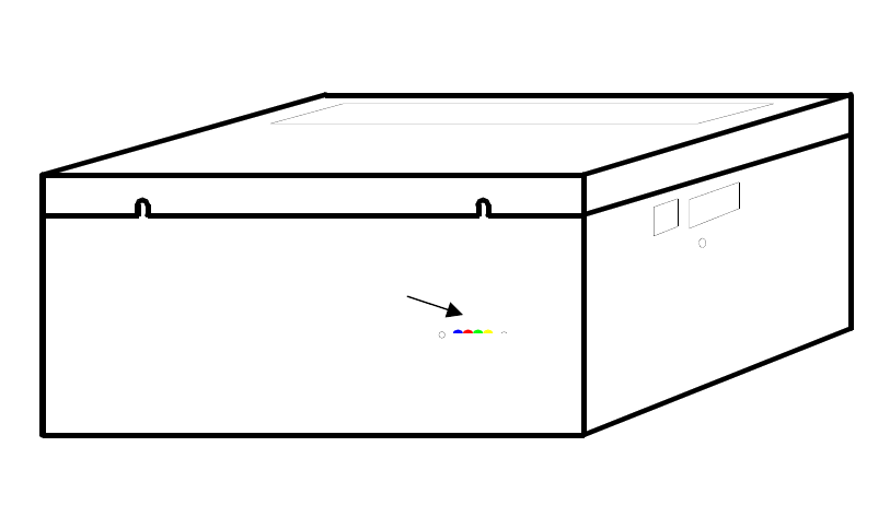
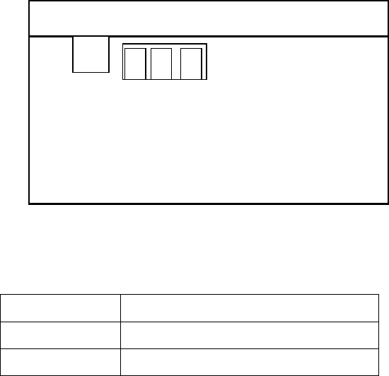
LED Error Indicators Description
LED Definitions
• L4 (Yellow) = Program Running Indicator
• L3 (Green) = Over-voltage Detection
(115±10%Vac, 60Hz and 230±10%Vac, 50Hz)
• L2 (Red) = Overheat Detection
• L1 (Blue) = Continuous 100 times Operation Counting
Error Types
Note: If any of following errors occurs, the corresponding LED will turn on and
FastPad will lock up. Turn the power switch off/on to reset the unit.
• [Red] = Deactivating coils have overheated. Allow the unit to cool down
and reapply power.
• [Green] = Over-voltage detection of the power source (10% tolerance:
115±10%Vac@60Hz and 230±10%Vac@50Hz). Remove power until
the power source is brought within required limits.
• [Red] and [Yellow] = 100 times continuous deactivation count has
been reached. In order to prevent system overheating, allow the
system to cool down and reapply the power.
• [All LEDs On] = Deactivator coils current has exceeded the limit.
Reapply power to the unit.
FAST PAD
CONTROL BOX
TM
LAN
REMOTE CONTROL
L1L2L3L4
CONTROL BOX - FRONT VIEW
LED Error Indicators
16
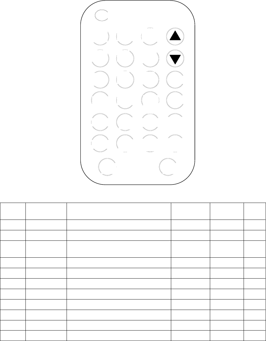
IR REMOTE CONTROL KEYPAD DESCRIPTION
Control Keys Description & Default Parameters Table
Key ID Button Parameters Description Default
Value
Valid
Range Page
PSW Activates the Control Box IR Receiver NA NA 15
B SYN Sync Adjustment 3 0 to 99 16
H MIN
Minimum Signal Adjustment
(Sensitivity adjustment) 3 0 to 8 19
D NSE Noise Display (2 channels) NA 0 to 8 17-18
E DFT Return to Default Settings 0 0 to 1 19
F TX OFF Media Products Deactivation 0 0 to 1 19
L ARM RST Alarm Count Reset 0 0 to 1 20
P PC Password change 68 (*Note) 0 to 99 20
S SA Save Parameters to Flash ROM NA NA 20-21
CON Confirm Parameters Input NA NA
EX Exit NA NA
* NOTE: The default password (68) can be changed with the PC button. Thereafter the
system will use the new number as the default password. The new password will remain
saved even after power off. THIS IS A NON-RECOVERABLE ACTION. KEEP THE NEW
PASSWORD IN A SAFE LOCATION IN CASE YOU FORGET IT.
SA EX
MIN2
MIN1
RE
GN SYN
NSE
A
RM
OFF
A
RM
RST
DFT
PC
TX
OFF
0
89
7
4
5
6
21
CON
PSW
3

17
TUNING PROCEDURES & TIPS
There are two main potential problems that will affect FastPad’s functioning
and performance.
Problem #1
The deactivator’s detection range does not match the deactivation range.
If the detection range is too short (low sensitivity for the receiver), it will
decrease the system’s deactivation distance. But if the detection range is
bigger than the deactivation range, it will cause false deactivation.
Normally the FastPad deactivates labels 10cm above the antenna surface in
all label orientations, so please tune Minimum Signal Adjustment to set the
deactivator to the appropriate detection range. This adjustment is described
under the heading “Key ID H” on page 19.
Problem #2
The deactivator exhibits false alarms (or causes other systems to do so)
without tags or labels in the detection zone.
Usually interference is caused by a phase difference between different AM
products at different locations. In this case, try to hunt on an appropriate B
value (sync value), eliminating cross talk with nearby AM systems.
Exercise patience in trying every 5 increments of the B value, checking the
noise value after confirmation. If other AM systems burst transmissions come
into the FastPad tag signal window, you will get a very high noise value (e.g.
6-8). Continue increasing the B value until you get a relatively small noise
value (e.g. 1-3) and continue to monitor it until you have confirmed that other
AM systems can successfully function without false alarms.
FastPad has a totally adjustable sync value from 0 - 99, each step equaling
34µs, with a total adjustable Tx delay from 0 – 3.366ms. (Refer to page 16,
under the heading “Key ID B Sync Adjustment”).
18
REMOTE CONTROL PROGRAMMING
Point the IR Remote Control to the Interface Window at one side of the
Control Box to operate the infrared communicator.
The panel normally displays the alarm count when not receiving any control
signals from remote control. The alarm count is displayed as in the above
picture – total count is 116 in this example. The number indicates the number
of times the deactivator has detected labels.
FAST PAD
CONTROL BOX
TM
LAN
REMOTE CONTROL
CONTROL BOX - SIDE VIEW
LAN REMOTE CONTROL
6
1 1
19
Press [PSW] button to activate the remote control, and then enter the
password (factory default is 68).
Input the number 68 (or the new password if you have changed it).
Press [CON] to instruct the Control Box to accept the password.
Note: Entering the wrong password input will disable the panel from further
instructions. Exit and re-press PSW to enter the correct password (see the
picture below). After THREE successive attempts with the wrong password
the remote control will be completely disabled. At this point you must turn the
unit on/off and begin again.
LAN REMOTE CONTROL
0
LAN REMOTE CONTROL
8
0
6
LAN REMOTE CONTROL
r E
r
20
When the correct password is verified, the LEDs will display as per the
following picture and wait for configuration type input.
Key ID “B” - Sync Adjustment (range: 0-99; increment: 1)
This adjustment sets the time from zero crossing point to the start point of
burst transmission. It is used for eliminating cross talk between different
systems. In most cases the default b-1 value will achieve system stability with
respect to other AM products.
Press [SYN] and the LEDs will display as shown below.
Input the number for the parameter.
Press [CON] to see the noise conditions.
Note: The adjustable range is 0-99 (0 – 3.366ms), with each increment
equaling 34µs. (34µs x 99 total increments = 3366µs = 3.366ms)
LAN REMOTE CONTROL
-
LAN REMOTE CONTROL
1 b
21
Under this mode, you can also see the different noise condition at a different
phase. If there is a phase problem, other AM systems’ burst transmission will
interfere with FastPad’s receiver, and you will see a large noise indication in
D1, D2.
Key ID “D” - Noise Condition Display
(Valid parameters: 1,2,3,4 - see configuration table below)
The LEDs display the signal level number, with a level range from 0-8.
Note: When in the noise condition display mode, the alarm will be deactivated
until you exit this mode.
Press [NSE] and the LEDs will display as shown below.
Input a number for the parameter.
Press [CON] to accept the parameter.
LAN REMOTE CONTROL
7 -
LAN REMOTE CONTROL
0
d
22
After confirmation, the panel will display a different signal or noise level from
the specific antenna channel.
Noise Condition Display Configuration Table
Value Function Description Detection Purpose
0 Shut down tag or noise window
display.
D1 Tag window display for channel 1. Detect tag by antenna CH1.
D2 Tag window display for channel 2. Detect tag by antenna CH2.
D3 Average noise window display for
channel 1.
Monitor long time average noise
received by antenna CH1.
D4 Average noise window display for
channel 2.
Monitor long time average noise
received by antenna CH2.
Note: D3/D4 indicate the average noise level and also the weighted Minimum
Signal Adjustment value. It gets the MAX value between average noise and
MIN value. Therefore, if MIN (H value) is increased to be bigger than the
average noise level, D3/D4 will indicate only H value instead of average noise
value.
LAN REMOTE CONTROL
2
-
23
Key ID “H” - Minimum Signal Adjustment (valid range: 0-8, increment 1)
Lowering this number will increase the label detection sensitivity of the
FastPad, but will also increase the risk of false deactivation. Vice versa,
raising it will decrease the sensitivity or detection range to adapt to
deactivation range.
While there are two antenna channels, FastPad has only one H value
adjustment, and it will apply to both of the antenna channels for minimum
signal adjustment.
Press [MIN]. The LEDs will display as shown as below
Input number for the parameter.
Press [CON] to accept the parameter.
Key ID “E” – Load Default Settings (default value: 0; valid range: 0-1)
Value Action
0 Initial state, no meaning
1 Load default settings
Input value 1 will load the default settings (refer to the Default Parameters
Table on page 10).
LAN REMOTE CONTROL
0
H
24
Key ID “F” – Low Power Deactivation Settings
(default value: 0; valid range: 0-1)
Value Action
0 Normal deactivation strength
1 Low power deactivation for media products
Press [Tx OFF]
Input number for the parameter.
Press [CON] to accept the parameter.
(Inputting “1” will lower the deactivation power for magnetic media products)
Key ID “L” – Alarm Count Reset (default value: 0; valid range: 0-1)
Value Action
0 Initial state, no meaning
1 Reset alarm count
Press [ARM RST]
Input number for the parameter.
Press [CON] to accept the parameter.
(Inputting “1” will reset alarm count to 0)
Key ID “P” - Password Change (default value: 68; valid range: 0-99)
The password can be changed in this mode from the factory default to your
choice. Press the confirm button after input to activate the password.
Note: If you change from the default password, save the new one in a safe
place because if you forget it there will be no way to access the unit.
Low Power Deactivation is strongly recommended
for magnetic media products such as pre-recorded
audio tapes, video tapes, floppy disks, etc.
25
Exit button
Press [Exit] to return to Alarm counter display status.
Save button
This button will save all current parameters to Flash ROM, so when power is
shut down the parameters will be saved. Next time the system reboots it will
load all the parameters from Flash ROM.
Press [Save]. The LEDs will display as shown below.
Input 1
Press [CON] to accept the current parameters.
***
LAN REMOTE CONTROL
1 S

Page: 31
Information on the following pages provides important safety
guidelines for both Operator and Service Personnel. Specific
warnings and cautions will be found throughout the manual
where they apply, but may not appear here. Please read and
follow the important safety information, noting especially
those instructions related to risk of fire, electric shock or injury
to persons.
WARNING
Any instructions in this manual that require opening the
equipment cover or enclosure are for use by qualified service
personnel only. To reduce the risk of electric shock, do not
perform any servicing other than that contained in the
operating instructions unless you are qualified to do so.
Symbols and Their Meanings
The exclamation point within an equilateral triangle alerts
the user to the presence of important operating and
maintenance (servicing) instructions in the literature
accompanying the equipment.
The fuse symbol indicates that the fuse referenced in the
text must be replaced with one having the ratings indicated.
I
mportant Safeguards and
R
e
g
ulator
y
Notices

Page: 32
Danger
Electrical potential is still applied to some internal
components even when the power switch/breaker is in the
off position. To prevent electrical shock when working on
this equipment, disconnect the AC line cord from the AC
source before working on any internal components.
A residual voltage may be present immediately after
unplugging the system due to slow discharge of large
power supply capacitors. Wait 30 seconds to allow
capacitors to discharge before working on the system.
Warnings
Heed all warnings on the unit and in the operating
instructions.
Do not use this equipment in or near water.
Disconnect AC power before installing any options.
The attachment plug receptacles in the vicinity of the
equipment are all to be of a grounding type, and the
equipment grounding conductors serving these are to be
connected to earth ground at the service equipment.
This equipment is grounded through the grounding
conductor of the power cord. To avoid electrical shock,
connect the power cord to the equipment and plug it into a
properly wired receptacle before connecting the equipment
inputs and outputs.
Route power cords and other cables so that they are not
likely to be damaged.
Do not wear hand jewelry or watches when troubleshooting
high current circuits, such as the power supplies.
During installation, do not use the door handles or front
panels to lift the equipment as they may open abruptly and
injure you.

Page: 33
To avoid fire hazard, use only components of the specified
type, voltage and current rating as referenced in the
appropriate parts list.
Always refer fuse replacement to qualified service
personnel.
To avoid explosion, do not operate this equipment in an
explosive atmosphere unless it has been specifically
certified for such operation.
Have qualified personnel perform safety checks after any
completed service.
Risk of electric shock is present. A grounded circuit
conductor (neutral) is provided with over current protection.
Test all components before touching.
Cautions
To prevent damage to equipment when replacing fuses,
locate and correct the trouble that caused the fuse to blow
before applying power.
Verify that all power supply lights are off before removing
the power supply or servicing equipment.
Use only specified replacement parts.
Leave the base of the system clear for air exhaust cooling
and to allow room for cabling. Slots and openings in the
system are provided for ventilation. Do not block them.
To prevent damage to this equipment read the instructions
in this document for proper input voltage range selection.
Circuit boards in this equipment are densely populated with
surface mount and ASIC components. Special tools and
techniques are required to safely and effectively
troubleshoot and repair modules that use SMT or ASIC
components. For this reason, service and repair of products
incorporating surface mount technology are supported only
on a module exchange basis. Customers should not
Page: 34
attempt to troubleshoot or repair modules that contain SMT
components. It assumes no liability for damage caused by
unauthorized repairs. This applies to both in- and
out-of-warranty products.
Power Cord Notices
North American Power Supply Cords
This equipment is supplied with an external power line at
one end and a molded receptacle terminal block at the
other end. Conductors are color coded white (neutral),
black (line) and green or green/yellow (ground).
Operation of this equipment at voltages exceeding 130 VAC
will require power supply cords which comply with NEMA
configurations.
International Power Supply Cord
This equipment is supplied with an external power line at
one end and a molded receptacle terminal block at the
other end. Conductors are CEE color coded—light blue
(neutral), brown (line) and green/yellow (ground). Other IEC
320 C-13 type power supply cords can be used if they
comply with the safety regulations of the country in which
they are installed.

Page: 35
Before You Install
Introduction
Congratulations on your purchase of one of the finest EAS
systems on the market. This is the Installation Instructions
manual.
Receiving Inspection
Inspect all shipping containers for any signs of damage. If
any is found, notify the shipping company. If there is no
obvious damage, continue with the unpacking instructions.
Unpacking Instructions
Place the containers on a flat level surface with enough
room to move the container around as needed. Remove all
the remaining manuals. Compare the manuals against the
Inventory sheet and make a note of any discrepancies.
Carefully remove the contents of container and place on a
flat level surface. Compare the contents with the Part List to
ensure that there no missing items. Make a note of any
discrepancies.
Equipment Inspection
Inspect all equipment for damage. Items to specifically
check, and damage to look for, are listed below:
All connectors for bent or broken pins
Cables for crimped or broken wires
Plastic housing for any obvious signs of damage
If any damage is found, contact Customer Service at the
telephone number in the front of this manual. If any item is
damaged, DO NOT make any power or signal connections
to the unit unless otherwise advised to do so by Customer
Service.

Page: 36
If there are any discrepancies between the Manual Set
Inventory sheet and the manuals received, or between the
Packing List and items received, contact Customer Service
at the telephone number at the front of this manual. If there
are no discrepancies and either no damage, or
GVG-advised correction action is made, continue with this
manual.
Facility Checklist
The following checklist is a synopsis of information found in
the appropriate Installation Planning Guide. The Planning
Guide should be referred to for detailed site preparation
information.
Ensure that there are sufficient AC power outlets of the
required 3-prong grounded type and amp rating for the
intended equipment.