WIESON Technologies TPMS-8300 Tire Pressure Monitoring System User Manual
WIESON Technologies Co., Ltd. Tire Pressure Monitoring System
User manual

SC-T8000 Series TPMS
Fast Installation Guide
Bluewave Technology Co., LTD.
Tel: 886-2-23451989 Fax: 886-2-23450177
2F.-1, No.5, Lane 178, Jhuangjing Rd.,
Sinyi District, Taipei City 110, Taiwan, R.O.C.
http://www.7brains.com/
Email: support@7brains.com
2007/4/18
─────────────────────────────── SC-T8000 Fast Installation Guide
Installation
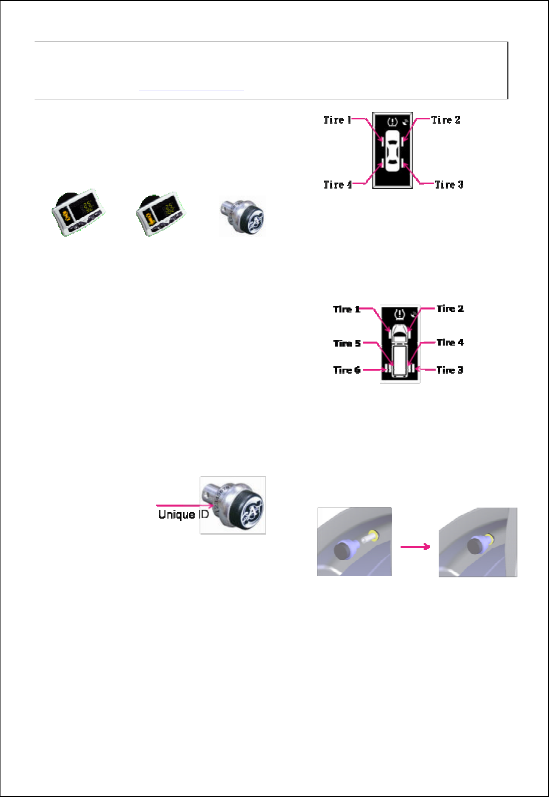
1. Check Components
Receiver(Passenger) Receiver(Truck) T-Type Sensor
Receiver Sensor
SC-T8000 1 4
SC-T8060 1 6
SC-T8080 1 8
SC-T8100 1 10
SC-T8120 1 12
One Power Cord
One Sucker & Fixture
* attention: Four-wheeled passenger and
truck’s receivers are different. Please
check the left-circle of receiver.
2. Check Sensor Identification
Number (Sensor ID) and Set
2.1 Each sensor should be
assigned a unique
identification
number (ID) which
was marked on the top of sensor.
2.2 The last two number of sensor ID has
given the locating tire position, the
order is as following:
* SC-T8000 ID locating position
01:left-front tire 02:rght-front tire
04:left-rear tire 03: right-rear tire
SC-T8060 ID locating position
01:left-front tire 02:right–front tire
05:left-rear tire right 03:righr -rear tire right
06:left-rrear tire left 04:righr-rear tire left
3. Install the Sensor into Wheel
3.1 Screw down the original valve cap.
3.2 Follow the ID’s last two number to
install the right tire (please refer to the
2.2 illustration)
Note: Since sensors being electric
isolation processed before shipping, it is
recommended, for the first installation,
to rotate sensor forward and backward
several times to remove isolation
coating and ensure the conductivity
between sensor and valve stem.
3.3 Screw fixture: Prevent sensor from easy
removing also in favor of sensor
Welcome to Bluewave Super Cat T-Type 8000 Series Tire Pressure Monitoring System (SC-T8000
TPMS). This Fast installation Guide is intended to give you a fast overview of the key steps required to
install your SC-T8000 Series TPMS. For more detailed information, please refer to the SC-T8000 Series
TPMS User’s Manual.(http://www.7brains.com)
─────────────────────────────── SC-T8000 Fast Installation Guide
stationary.
Note:
(1) User may ignore this fixture, when
causing inflation hassle concerns.
(2) To ensure LED template display
correctly coincide with actual sensor
position, Please follow step
4-Sensor alignment in order to get
right pressure and temperature
from right sensor.
4. Sensor alignment
Plug the attached power cord into cigarette
lighter directly, then activate the receiver.
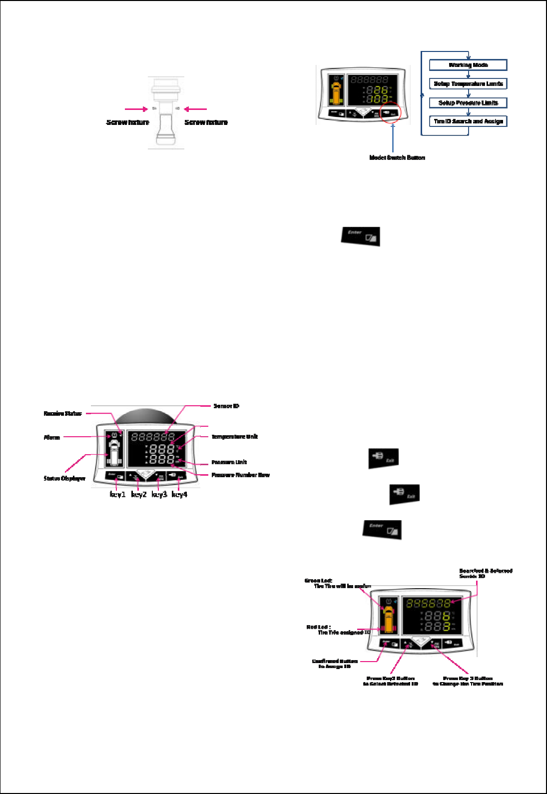
4.1 Operation mode illustration
SC-T8000 series provides various
operating mode to set different
parameter, under normal condition,
please follow the above illustration
“Key4(Exit)for 0.5 second into
different operating modes in order to
make use of different functions and
parameter sets.
4.2 Preset ID
Under normal condition,
press ,check the first installed
tire ID is righr or not, and then press
Enter , check tire ID 2, 3, and 4.
If the sensors ID are all correctly located,
then you can ignore the next steps.
(Section 4.3).
4.3 ID search and set
under normal condition,do as the
followings:
à Press (for 0.5 second)
à Press twice
à Press into ID search
Make sure the sensor is consistent with the main
engine geared position then press Key1 (Enter),
─────────────────────────────── SC-T8000 Fast Installation Guide
follow step 3 to install the next sensor
installation, after finishing press Key4 (Exit).
*attention: Finished installing, LED
shows “red “, If you set different sensor
ID in the same place, the LED will
disappear, at this moment you must
reset the sensor.
〔Signal〕
1. Normal:
When tires operate in normal condition, LED
shows “green” light. Every 8 sec., the “orange”
light takes turn to show each tire’s condition.
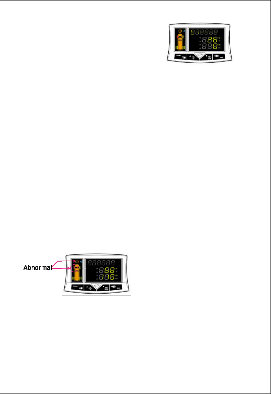
2. Abnormal:
When tire is in over-heated, over-pressured, or
under-pressured condition, LED shows “red”
light, locks on the position of over-heated tire
with “beep” sound.
*NOTE:Two tires are abnormal at the same time,
it will be fixed on the abnormal status.
3. Receiver did not receive Data:
If receiver can not receive updated tire messages
over 10 mins., LED shows abnormal indication.
Example:
Left-front tire didn’t receive data, shows “ t l ----”.
Right-front tire didn’t receive data, shows “ t2 ----”.
Left-rear tire didn’t receive data, shows “ t3 ----”.
Right-rear tire didn’t receive data, shows “ t4 ----”.
*attention: The abnormal signal will be
disappear after once messages received.
If long time no new information, please
check your sensor.
〔FCC Notice〕
The changes or modifications not expressly
approved by the party responsible for
compliance could void the user’s authority to
operate the equipment.
THIS DEVICE COMPLIES WITH PART
15 OF THE FCCRULES. OPERATION IS
SUBJECT TO THE FOLLOWING TWO
CONDITIONS:
(1) THIS DEVICE MAY NOT CAUSE
HARMFUL INTERFERENCE
(2) THIS DEVICE MUST ACCEPT ANY
INTERFERENCE THAT MAY CAUSE
UNDESIRED OPERATION.
Caution: Any changes or modifications in
construction of this device which are not
expressly approved by the party responsible
for compliance could void the user’s
authority to operate the equipment.
910805 2
FCC Notice:
Notice : The changes or modifications not expressly approved by the party responsible
for compliance could void the user’s authority to operate the equipment.
IMPORTANT NOTE: To comply with the FCC RF exposure compliance requirements, no change
to the antenna or the device is permitted. Any change to the antenna or the
device could result in the device exceeding the RF exposure requirements
and void user’s authority to operate the device.
This device complies with Part 15 of the FCC Rules. Operation is subject to the following two
conditions: (1) this device may not cause harmful interference, and (2) this device must accept any
interference received, including interference that may cause undesired operation.