WIRELESS TAG TECHNOLOGY WT51822 Bluetooth Low Engergy 4.0 Module User Manual Wireless Tag nRF51822 04AT
WIRELESS-TAG TECHNOLOGY CO., LIMITED Bluetooth Low Engergy 4.0 Module Wireless Tag nRF51822 04AT
UserManual.wiki
>
WIRELESS TAG TECHNOLOGY
>
WT51822 User Manual
User Manual
Navigation menu
Upload a User Manual
Namespaces
Wiki Guide
HTML
PDF
Info
Views
User Manual
Discussion / Help
Navigation
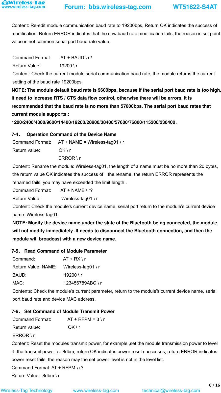
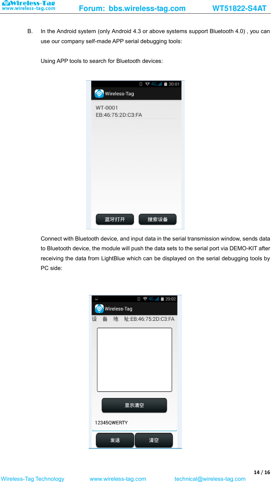
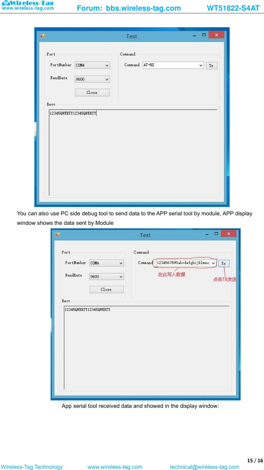
![Forum: bbs.wireless-tag.com WT51822-S4AT 8 / 16 Wireless-Tag Technology www.wireless-tag.com technical@wireless-tag.com data is beyond the scope required by the serial number, the serial number of the module supports the content within 0000-FFFF. 7-12、 Setting Command of Bluetooth Broadcast Interval Command Format: AT + ADP = 500 \ r Return value: OK \ r ERROR \ r Contents: Bluetooth Broadcasting valid interval is 100ms-4000ms, if re-configure the Bluetooth radio interval to 500ms, returns OK indicates reset successfully, ERROR indicates reset failed. 7-13、 Reset Command of Bluetooth Connection Interval Command Format: AT + CIT = 300 \ r Return value: OK \ r ERROR \ r Content: An active Bluetooth connection interval is 20ms-2000ms, if resetting Bluetooth connection time interval to 300ms, returns OK indicates reset successfully, the return ERROR indicates reset failed. NOTE: The module does not support dynamic modification process connection interval, only work when restart the module after modification. 7-14、 Setting command of low-power sleep mode Command Format: AT + SLEEP \ r Return value: OK \ r Content: To reduce module power consumption, module in idle state can be used to set to sleep by the sleep command, and then Bluetooth is turned off, power consumption is reduced. Module in sleep mode can be wake-up by an external interrupt, external interrupt wake-foot there are: enable, test, reset three pins, any one external pin interrupt, the module can wake from sleep, wake up way: reset pin falling edge wake up, pin state switches from high level to low level; enable, test Pin rising edge wake up, the pin status is switched from low to high; the module wake-up reset to re-enter the work state. 8. Test Mode of Transparent Transmission When the users get the module samples, they always want to first test module Bluetooth functions without the support from hardware serial. According to this usage, the module designed Bluetooth transparent transmission test mode to give a high level signal to the test mode control foot (TEST pin) to control Bluetooth module into the transparent transmission test mode. At this time, the module can normally connect with the mobile device terminal APP through Bluetooth. The module will automatically transmitted back to the mobile terminal equipment after receiving the data transmitted from APP, realize two-way data communication function between Bluetooth module and the mobile device terminal. After the test, released TEST pin high level, re-powering or reset the module to enter normal operation status. 9. BLE Protocol Description(app port) [Service UUID: 0x1234 ]](https://usermanual.wiki/WIRELESS-TAG-TECHNOLOGY/WT51822/User-Guide-2743721-Page-8.png)
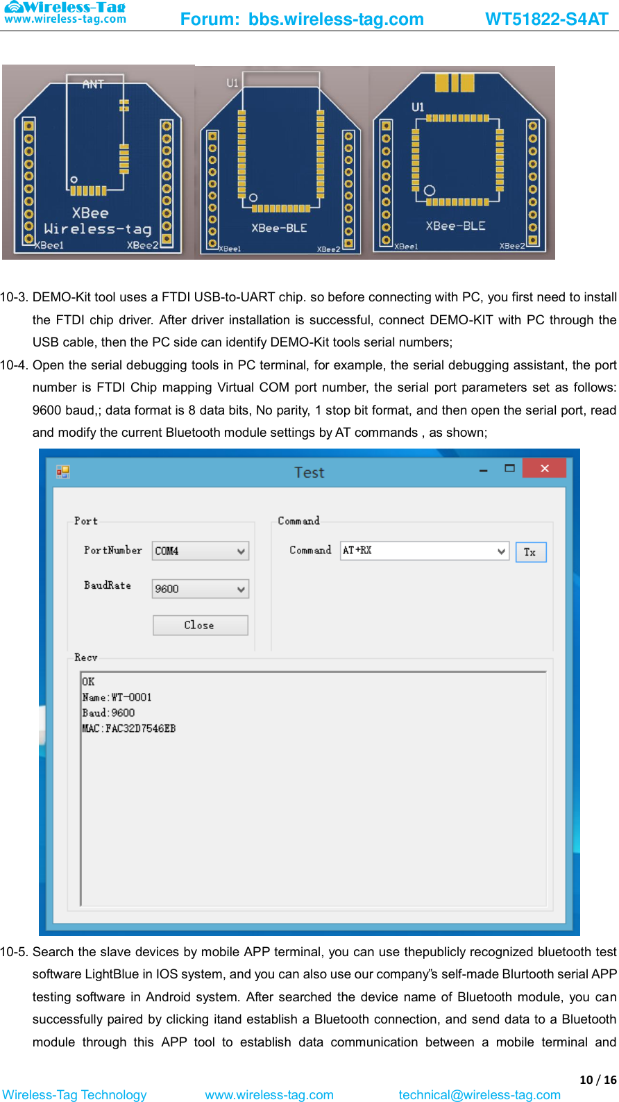
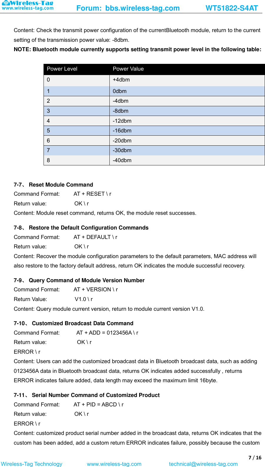
![Forum: bbs.wireless-tag.com WT51822-S4AT 9 / 16 Wireless-Tag Technology www.wireless-tag.com technical@wireless-tag.com Eigen values characteristic 0x1235 Write Without Response [Service UUID: 0x1234] Eigen values characteristic 0x1236 Notify 10. Application Examples of Bluetooth Module 10-1. Accessibility BLE-DK, nRF51822-DK is tool designed for easy use its Wireless-Tag BLE Bluetooth nRF51822-01/02/04. You can easily connect the Bluetooth module with PC through the nRF51822-DK. The Bluetooth module works as slave device, can be searched and matched by Bluetooth master terminal. After matched, input the data to Bluetooth module via serial port debugging tools and the Bluetooth module resent the data to the master module; at the same time, the Bluetooth module can send the data received from the master module to the serial port debugging tools. Developers can easily check the data content between the Bluetooth module and the master terminal. 10-2. The connection method of DEMO-Kit Tools and Bluetooth module: DEMO-Kit Tools interface is the currently popular XBee interface. Bluetooth module connect with Kit Tools by XBee adapter board. Welding the module posted in the corresponding XBee adapter board, and then inserted the adapter board into the Kit tools. XBee adapter plate shown as below:](https://usermanual.wiki/WIRELESS-TAG-TECHNOLOGY/WT51822/User-Guide-2743721-Page-9.png)