WIRELESS TAG TECHNOLOGY WT51822 Bluetooth Low Engergy 4.0 Module User Manual Wireless Tag nRF51822 04AT
WIRELESS-TAG TECHNOLOGY CO., LIMITED Bluetooth Low Engergy 4.0 Module Wireless Tag nRF51822 04AT
User Manual
Forum: bbs.wireless-tag.com WT51822-S4AT
1 / 16
Wireless-Tag Technology www.wireless-tag.com technical@wireless-tag.com
Wireless-Tag WT51822-S4AT
Bluetooth Low Energy 4.0 Module
DATASHEET
Description:
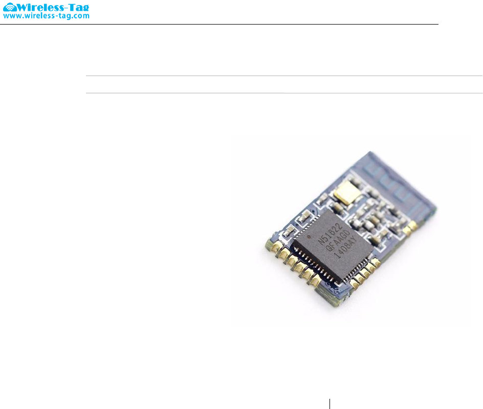
WT51822-S4AT is a high performance ,low power
radio transmit and receive system module use Nordic
BLE 4.0 nRF51822 as the controller chips. It has the
smallest volume package in the industry, the size is
18.5*9.1*2.0, suitable for most applications which pay
more attention to the size. The module integrate the
complete standard low energy Bluetooth 4.0 protocol
stack S100 drive.
Customer's MCU is connected to the module by
UART port, it will automatically send a broadcast code
after the module starts. As the master, APP device
can scan and search the broadcast from module in
order to establish the connection. After success, it can
conduct two-way communication link with mobile device APP by serial port. Through UART interface, the
user can exchange data or control the communication parameters of module. The meaning of data is
defined by the upper application user. The mobile device can operate to the module through APP, the data
will receive by the module and pushed through UART MCU. After the module received a data packet from
the client MCU serial port, it will be automatically forwarded to the mobile device.
Features:
CPU: nRF51822-QFAA (ARM Cortex™-M0 32 bit processor)
Memory: 256KB flash + 16KB RAM memory
Transparent transmission (Bridged method) easy to use and fast, no Bluetooth protocol stack
development experience can use too.
The user interface uses a standard UART (TTL) Interface, bidirectional data read, easy to operate
Supports serial AT commands, the user can modify the basic parameters like the serial port baud rate,
name, MAC address of the module, etc.
Serial data packet length, single data packet can support data length up to 200byte;
Serial hardware enable control, low-power control applications
With the support under the test mode but not connect the serial mode, mutual communication between
test module and bluetooth master devices
Operating distance: 0~45m,class II level
Support System: IOS & Android
Supply voltage:3.3V
Module comes with PCB antenna, optional external antenna
Size: 18.5*9.1*2.0mm
Applications:
Electronic scales
Forum: bbs.wireless-tag.com WT51822-S4AT
2 / 16
Wireless-Tag Technology www.wireless-tag.com technical@wireless-tag.com
Electronic cigarette
Smart cups
Smart bracelet
Smart Watch
Bluetooth toys
Intelligent hardware
Smart Home
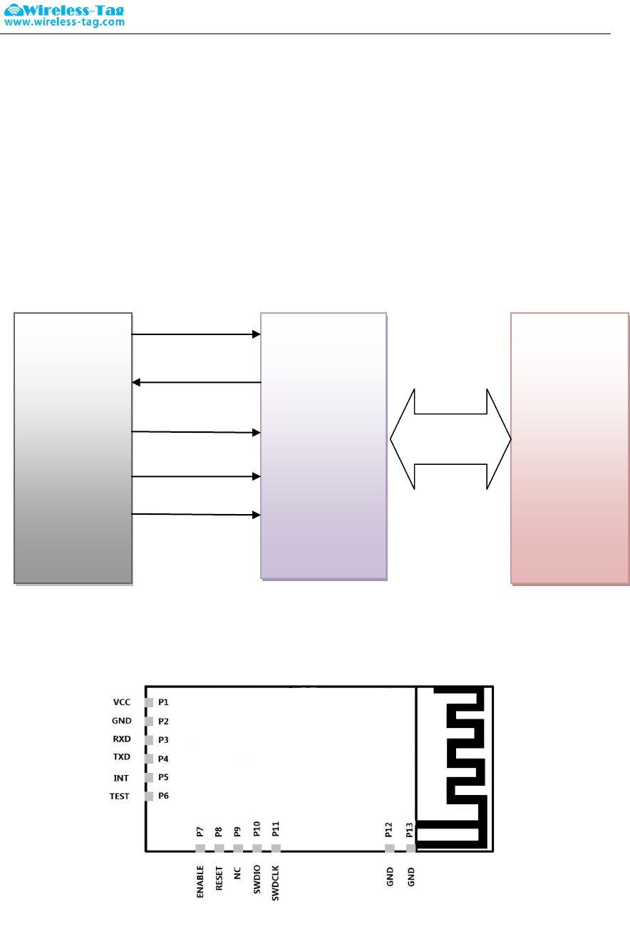
1. Work Mode Image
2. Module Pin Definitions
MCU
Application
circuit
BLE 4.0
Module
VCC
UART-TX
UART-RX
ENABLE
GND
APP
BLE Master
BLE 4.0
Top View
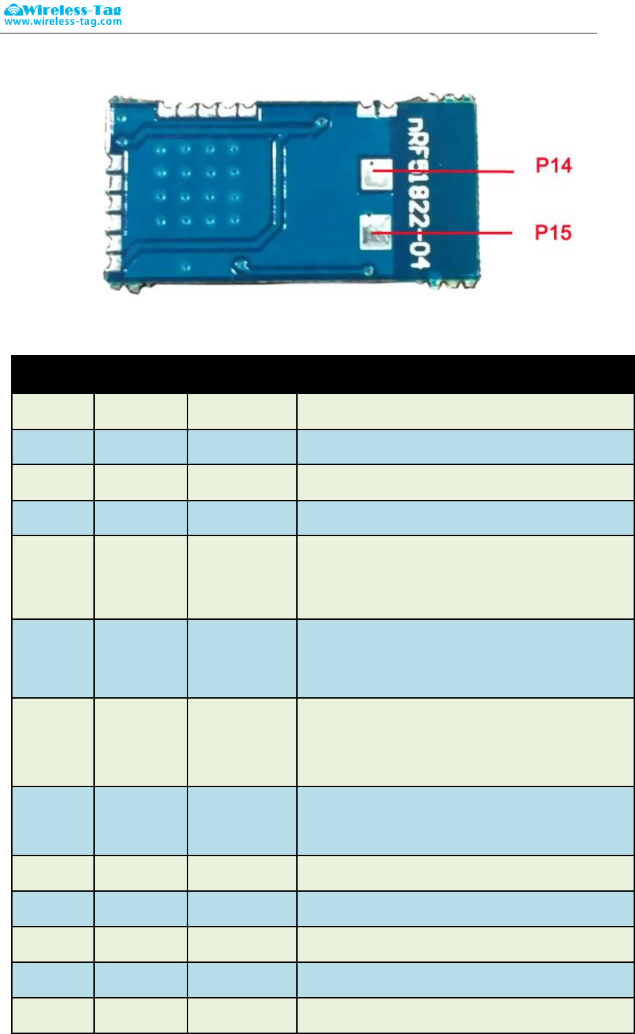
Bottom View
Forum: bbs.wireless-tag.com WT51822-S4AT
3 / 16
Wireless-Tag Technology www.wireless-tag.com technical@wireless-tag.com
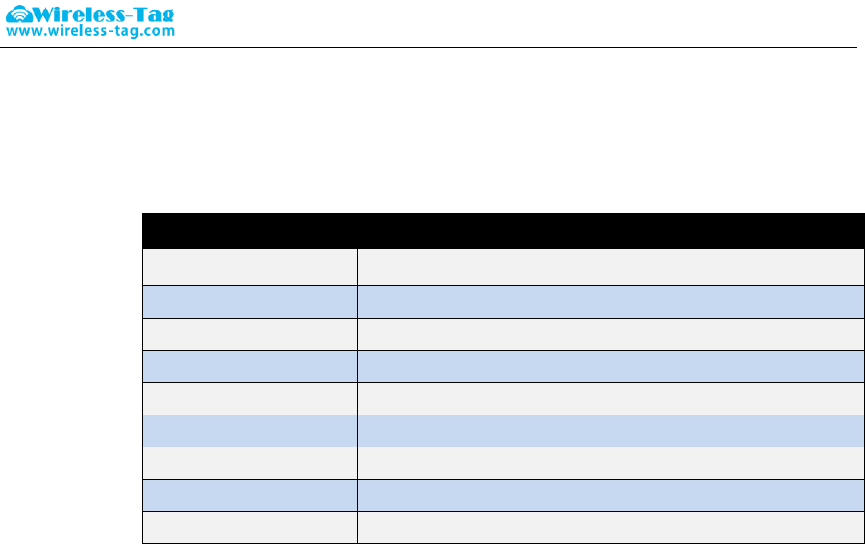
3. Pin Directions
No.
Chip pin
Module pin
Function Description
pin1
VCC
VCC
DC 2.5~3.6V
pin2
GND
GND
Ground
pin3
P0.01
RXD
UART--RX
pin4
P0.02
TXD
UART--TX
pin5
P0.03
INT
Interrupt output pin, the bluetooth will deliver output
100ushigh-level pulse signal tips after received the
primary-side data
pin6
P0.04
TEST
Test mode control pin, high level is effective, the module
will enter into the Bluetooth test mode after being set high,
the module will send back the received data
pin7
P0.09
ENABLE
Serial Port Enable pin, low level is effective. .Activate
module serial port function after set high, and the serial
port will close after being set low, which result in module
functions reduction.
pin8
P0.10
RESET
Serial port reset pin, low level restored, and the baud rate
restored to the default setting
pin9
P0.13
NC
No need to connect
pin10
SWDIO
SWDIO
Debug data input
pin11
SWDCLK
SWDCLK
Debug clock signal input
Pin12
GND
GND
Ground
Pin13
GND
GND
Ground
Forum: bbs.wireless-tag.com WT51822-S4AT
4 / 16
Wireless-Tag Technology www.wireless-tag.com technical@wireless-tag.com
Pin14
NC
NC
No connection
Pin15
NC
NC
No connection
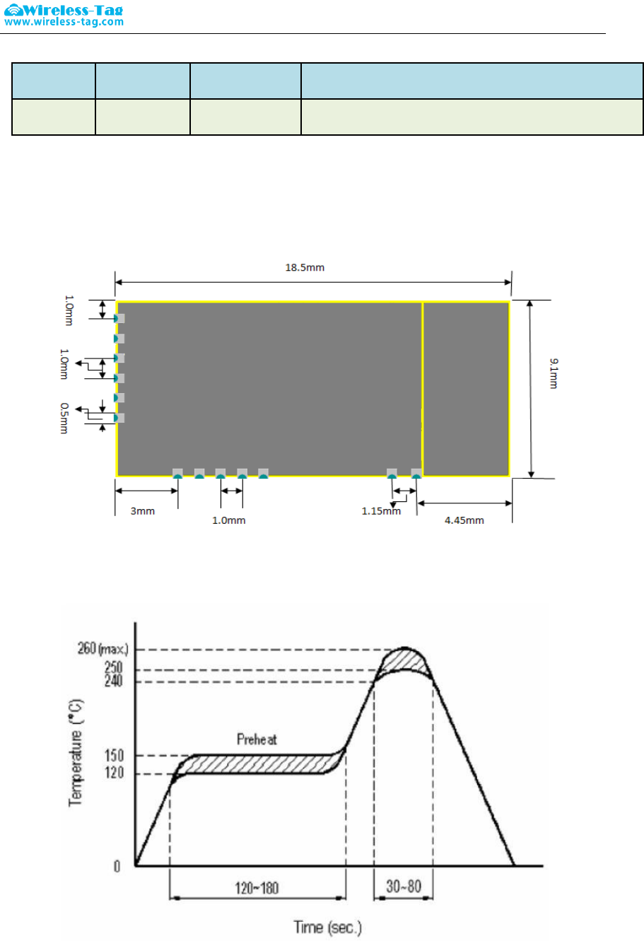
4. Module package size
5. Reflow reference to FIG.
6. The Manual for The Serial Transparent Transmission Protocol
Serial transparent transmission means that modules are connected with user MCU via a common
serial interface to establish a two-way communication between user MCU and mobile devices. The module
Top View

Forum: bbs.wireless-tag.com WT51822-S4AT
5 / 16
Wireless-Tag Technology www.wireless-tag.com technical@wireless-tag.com
can obtain at least 200bytes transmission data and automatically send the data by separated packets, each
wireless packet maximum load is 20byte. The data packet, which is sent to the module by mobile device
side, must send subcontracting automatically(1-20byte/package), the module will forward to the MCU serial
receiving port after receiving the data packet. Users can modify the module basic Bluetooth parameters
serial AT commands. For details, please check "serial AT command" description.
6-1、 Serial hardware protocol: default 9600bps. 8, No verify bit 1, Stop bit
6-2、 “Enable” serial ports enable control, low level enable module serial port function making
data communication with the client host MCU properly; high level closes the serial port function.
At this time, the module Bluetooth can still transmit broadcast code, and can be paired
connection, but you can not use the serial port functions;
6-3、 In order to save the size, the module uses the TXD / RXD double wire serial methods,
without increasing the data flow control. So it is not recommended to set the serial rate too high,
in caseof packet loss or error code, recommend to use 9600bps or other baud rates like no
higher than 38400bps;
6-4、 Bluetooth module default connection interval is 20ms, if you need to save power and adopt
low-speed forwarding mode, you can adjust Bluetooth connection interval via the AT command,
the longest interval Bluetooth connectivity is 2000ms;
7. Serial AT commands Description:
Module will automatically recognize and distinguish serial data, the data packet began with AT
character will be defaulted as AT commands and parsing, and will return the process results, so the data
under transparent transmission mode cannot begin with AT character.
7-1、 The test command
Command format: AT\r Syntax: AT \ r
Returning value: OK\r Return value: OK \ r
Content: send AT test commands, returning value OK indicates module AT commands tested
successfully.
7-2、 MAC address Operation Command
Command Format: AT + ADDR \ r?
Return Value: xxxxxxxxxxxx \ r
Content: Return the module‟s current MAC address: xxxxxxxxxxxx
Command Format: AT + ADDR = 123456789ABC \ r
Return value: OK \ r
Content: modify the module MAC address again: 123456789ABC, return value OK indicates the
success of reset MAC address.
Note: If the Bluetooth module modified the module MAC address successfully under being
connected state, but the module will not switch immediately to the new address , it needs to
disconnect the module , then the module will be broadcast with a new MAC address.
7-3、 Operation command of Serial Port Communication Baud-rate
Command format: AT + BAUD = 19200 \ r
Return value: OK \ r
ERROR \ r

Forum: bbs.wireless-tag.com WT51822-S4AT
6 / 16
Wireless-Tag Technology www.wireless-tag.com technical@wireless-tag.com
Content: Re-edit module communication baud rate to 19200bps, Return OK indicates the success of
modification, Return ERROR indicates that the new baud rate modification fails, the reason is set point
value is not common serial port baud rate value.
Command Format: AT + BAUD \ r?
Return Value: 19200 \ r
Content: Check the current module serial communication baud rate, the module returns the current
setting of the baud rate 19200bps.
NOTE: The module default baud rate is 9600bps, because if the serial port baud rate is too high,
it need to increase RTS / CTS data flow control, otherwise there will be errors, it is
recommended that the baud rate is no more than 57600bps. The serial port baud rates that
current module supports :
1200/2400/4800/9600/14400/19200/28800/38400/57600/76800/115200/230400。
7-4、 Operation Command of the Device Name
Command Format: AT + NAME = Wireless-tag01 \ r
Return value: OK \ r
ERROR \ r
Content: Rename the module: Wireless-tag01, the length of a name must be no more than 20 bytes,
the return value OK indicates the success of the rename, the return ERROR represents the
renamed fails, you may have exceeded the limit length .
Command Format: AT + NAME \ r?
Return Value: Wireless-tag01 \ r
Content: Check the module‟s current device name, serial port return to the module‟s current device
name: Wireless-tag01.
NOTE: Modify the device name under the state of the Bluetooth being connected, the module
will not modify immediately .It needs to disconnect the Bluetooth connection, and then the
module will broadcast with a new device name.
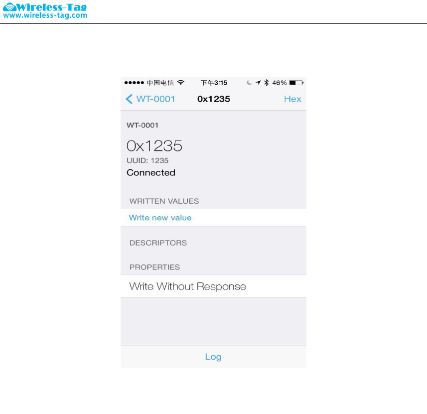
7-5、 Read Command of Module Parameter
Command: AT + RX \ r
Return Value: NAME: Wireless-tag01 \ r
BAUD: 19200 \ r
MAC: 123456789ABC \ r
Contents: Check the module‟s current parameter, return to the module‟s current device name, serial
port baud rate and device MAC address.
7-6、 Set Command of Module Transmit Power
Command Format: AT + RFPM = 3 \ r
Return value: OK \ r
ERROR \ r
Content: Reset the modules transmit power, for example ,set the module transmission power to level
4 ,the transmit power is -8dbm, return OK indicates power reset successes, return ERROR indicates
power reset fails, the reason may the set power level is not in the level list.
Command Format: AT + RFPM \ r?
Return Value: -8dbm \ r
Forum: bbs.wireless-tag.com WT51822-S4AT
7 / 16
Wireless-Tag Technology www.wireless-tag.com technical@wireless-tag.com
Content: Check the transmit power configuration of the currentBluetooth module, return to the current
setting of the transmission power value: -8dbm.
NOTE: Bluetooth module currently supports setting transmit power level in the following table:
Power Level
Power Value
0
+4dbm
1
0dbm
2
-4dbm
3
-8dbm
4
-12dbm
5
-16dbm
6
-20dbm
7
-30dbm
8
-40dbm
7-7、 Reset Module Command
Command Format: AT + RESET \ r
Return value: OK \ r
Content: Module reset command, returns OK, the module reset successes.
7-8、 Restore the Default Configuration Commands
Command Format: AT + DEFAULT \ r
Return value: OK \ r
Content: Recover the module configuration parameters to the default parameters, MAC address will
also restore to the factory default address, return OK indicates the module successful recovery.
7-9、 Query Command of Module Version Number
Command Format: AT + VERSION \ r
Return Value: V1.0 \ r
Content: Query module current version, return to module current version V1.0.
7-10、 Customized Broadcast Data Command
Command Format: AT + ADD = 0123456A \ r
Return value: OK \ r
ERROR \ r
Content: Users can add the customized broadcast data in Bluetooth broadcast data, such as adding
0123456A data in Bluetooth broadcast data, returns OK indicates added successfully , returns
ERROR indicates failure added, data length may exceed the maximum limit 16byte.
7-11、 Serial Number Command of Customized Product
Command Format: AT + PID = ABCD \ r
Return value: OK \ r
ERROR \ r
Content: customized product serial number added in the broadcast data, returns OK indicates that the
custom has been added, add a custom return ERROR indicates failure, possibly because the custom

Forum: bbs.wireless-tag.com WT51822-S4AT
8 / 16
Wireless-Tag Technology www.wireless-tag.com technical@wireless-tag.com
data is beyond the scope required by the serial number, the serial number of the module supports the
content within 0000-FFFF.
7-12、 Setting Command of Bluetooth Broadcast Interval
Command Format: AT + ADP = 500 \ r
Return value: OK \ r
ERROR \ r
Contents: Bluetooth Broadcasting valid interval is 100ms-4000ms, if re-configure the Bluetooth radio
interval to 500ms, returns OK indicates reset successfully, ERROR indicates reset failed.
7-13、 Reset Command of Bluetooth Connection Interval
Command Format: AT + CIT = 300 \ r
Return value: OK \ r
ERROR \ r
Content: An active Bluetooth connection interval is 20ms-2000ms, if resetting Bluetooth connection
time interval to 300ms, returns OK indicates reset successfully, the return ERROR indicates reset
failed.
NOTE: The module does not support dynamic modification process connection interval, only
work when restart the module after modification.
7-14、 Setting command of low-power sleep mode
Command Format: AT + SLEEP \ r
Return value: OK \ r
Content: To reduce module power consumption, module in idle state can be used to set to sleep by the
sleep command, and then Bluetooth is turned off, power consumption is reduced. Module in sleep
mode can be wake-up by an external interrupt, external interrupt wake-foot there are: enable, test,
reset three pins, any one external pin interrupt, the module can wake from sleep, wake up way: reset
pin falling edge wake up, pin state switches from high level to low level; enable, test Pin rising edge
wake up, the pin status is switched from low to high; the module wake-up reset to re-enter the work
state.
8. Test Mode of Transparent Transmission
When the users get the module samples, they always want to first test module Bluetooth
functions without the support from hardware serial. According to this usage, the module designed
Bluetooth transparent transmission test mode to give a high level signal to the test mode control foot
(TEST pin) to control Bluetooth module into the transparent transmission test mode. At this time, the
module can normally connect with the mobile device terminal APP through Bluetooth. The module will
automatically transmitted back to the mobile terminal equipment after receiving the data transmitted
from APP, realize two-way data communication function between Bluetooth module and the mobile
device terminal.
After the test, released TEST pin high level, re-powering or reset the module to enter normal
operation status.
9. BLE Protocol Description(app port)
[Service UUID: 0x1234 ]
Forum: bbs.wireless-tag.com WT51822-S4AT
9 / 16
Wireless-Tag Technology www.wireless-tag.com technical@wireless-tag.com
Eigen values
characteristic
0x1235
Write Without Response
[Service UUID: 0x1234]
Eigen values
characteristic
0x1236
Notify
10. Application Examples of Bluetooth Module
10-1. Accessibility BLE-DK, nRF51822-DK is tool designed for easy use its Wireless-Tag BLE Bluetooth
nRF51822-01/02/04. You can easily connect the Bluetooth module with PC through the nRF51822-DK.
The Bluetooth module works as slave device, can be searched and matched by Bluetooth master
terminal. After matched, input the data to Bluetooth module via serial port debugging tools and the
Bluetooth module resent the data to the master module; at the same time, the Bluetooth module can
send the data received from the master module to the serial port debugging tools.
Developers can easily check the data content between the Bluetooth module and the master terminal.
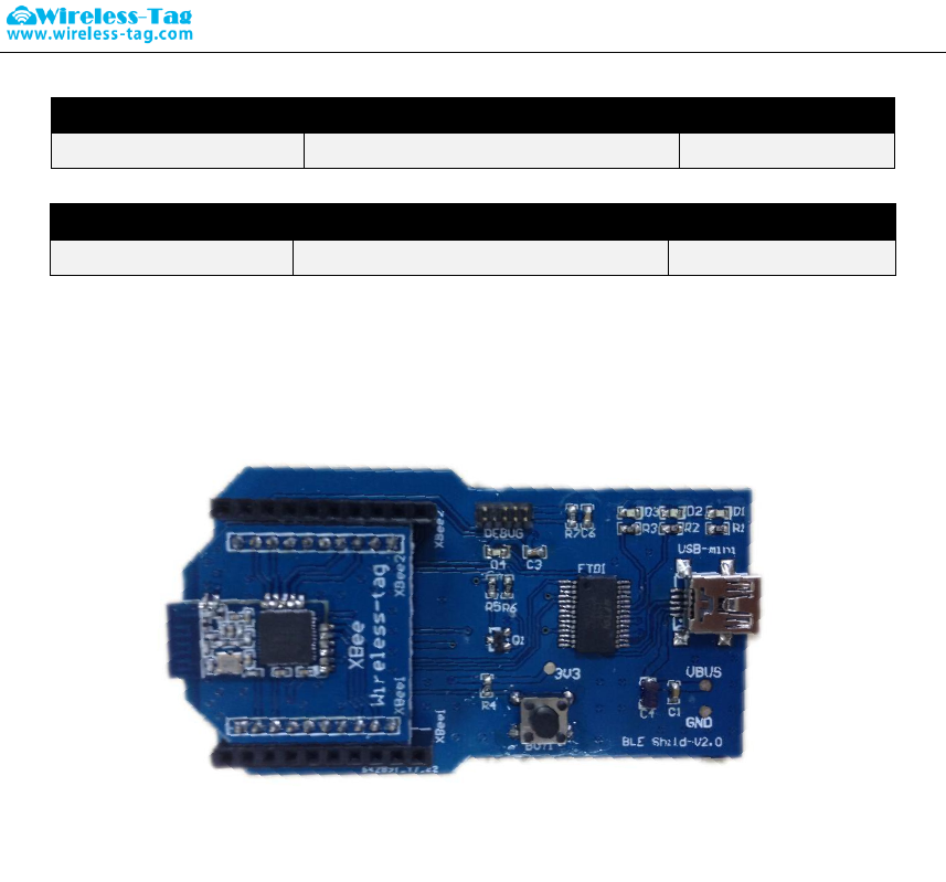
10-2. The connection method of DEMO-Kit Tools and Bluetooth module: DEMO-Kit Tools interface is the
currently popular XBee interface. Bluetooth module connect with Kit Tools by XBee adapter board.
Welding the module posted in the corresponding XBee adapter board, and then inserted the adapter
board into the Kit tools.
XBee adapter plate shown as below:
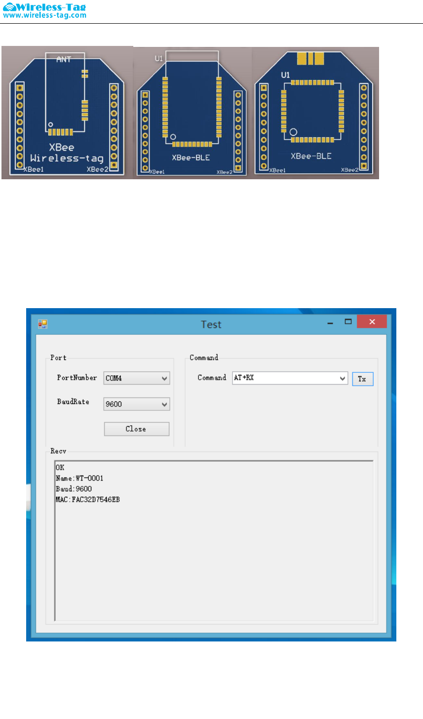
Forum: bbs.wireless-tag.com WT51822-S4AT
10 / 16
Wireless-Tag Technology www.wireless-tag.com technical@wireless-tag.com
10-3. DEMO-Kit tool uses a FTDI USB-to-UART chip. so before connecting with PC, you first need to install
the FTDI chip driver. After driver installation is successful, connect DEMO-KIT with PC through the
USB cable, then the PC side can identify DEMO-Kit tools serial numbers;
10-4. Open the serial debugging tools in PC terminal, for example, the serial debugging assistant, the port
number is FTDI Chip mapping Virtual COM port number, the serial port parameters set as follows:
9600 baud,; data format is 8 data bits, No parity, 1 stop bit format, and then open the serial port, read
and modify the current Bluetooth module settings by AT commands , as shown;
10-5. Search the slave devices by mobile APP terminal, you can use thepublicly recognized bluetooth test
software LightBlue in IOS system, and you can also use our company‟s self-made Blurtooth serial APP
testing software in Android system. After searched the device name of Bluetooth module, you can
successfully paired by clicking itand establish a Bluetooth connection, and send data to a Bluetooth
module through this APP tool to establish data communication between a mobile terminal and

Forum: bbs.wireless-tag.com WT51822-S4AT
11 / 16
Wireless-Tag Technology www.wireless-tag.com technical@wireless-tag.com
Bluetooth modules.
A. In the IOS system (only iphone4S or above version phones support Bluetooth 4.0) use
LightBlue to test module connect function.
Firstly, open iphone Bluetooth, run LightBlue APP, when LightBlue is running, it will
automatically search for the slave unit, the slave list will be displayed with some main
information, UUID Services, transmitting power, device names etc.
Click the slave unit you want to connect, iphone will connect with the salve, afterthis, the
program will automatically search all services from slave machine, as shown below.
Forum: bbs.wireless-tag.com WT51822-S4AT
12 / 16
Wireless-Tag Technology www.wireless-tag.com technical@wireless-tag.com
Enter into the service by clicking the cooresponding service , you can see some
characteristics included in the Services, shown as below
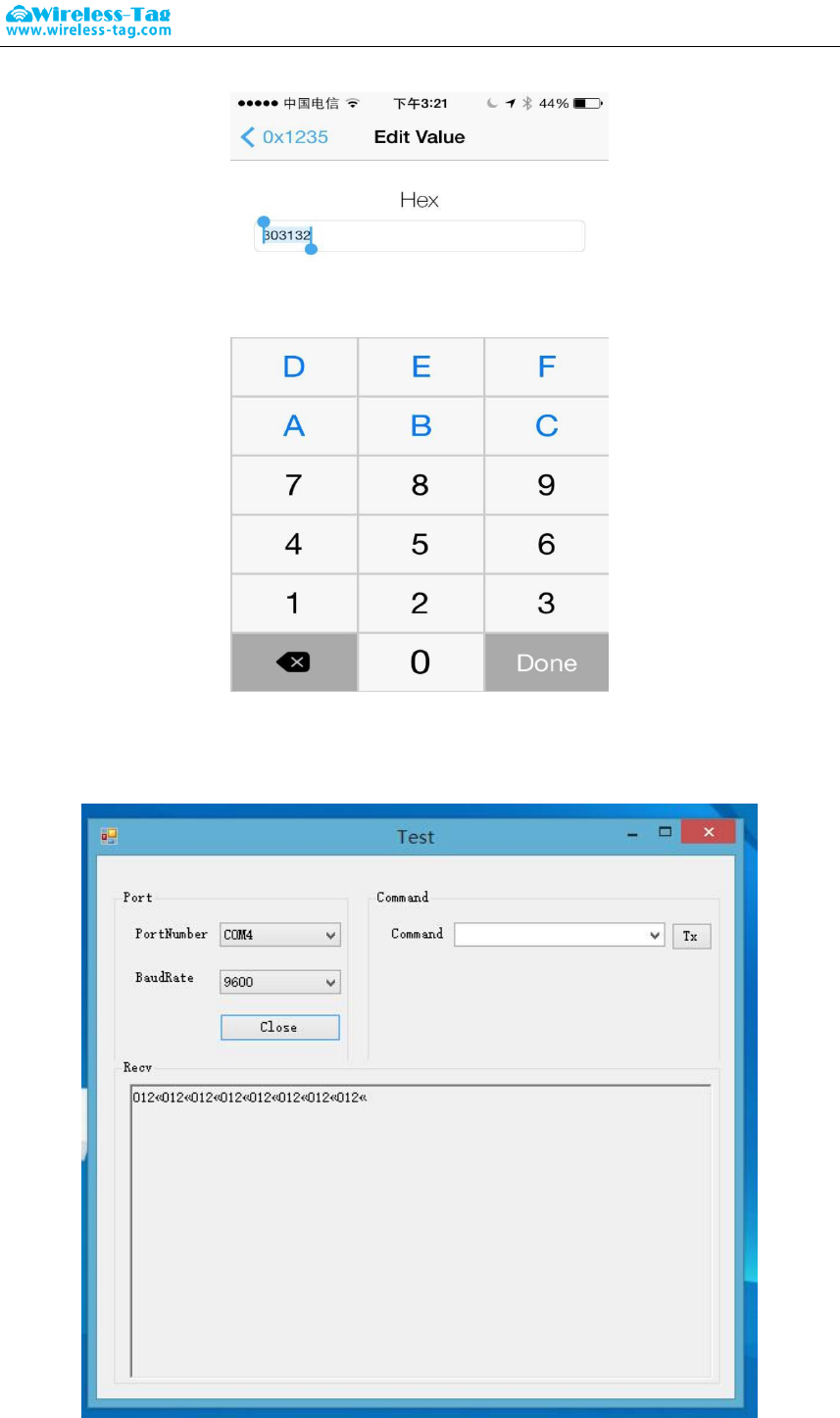
Click „Write new value‟, will enter into the communication field of Characteristic, write the
input value, as below:
Forum: bbs.wireless-tag.com WT51822-S4AT
13 / 16
Wireless-Tag Technology www.wireless-tag.com technical@wireless-tag.com
Module will push the data sets to the serial port via DEMO-KIT after receiving the data from
LightBlue which can be displayed on the serial debugging tools by PC side:
Forum: bbs.wireless-tag.com WT51822-S4AT
14 / 16
Wireless-Tag Technology www.wireless-tag.com technical@wireless-tag.com
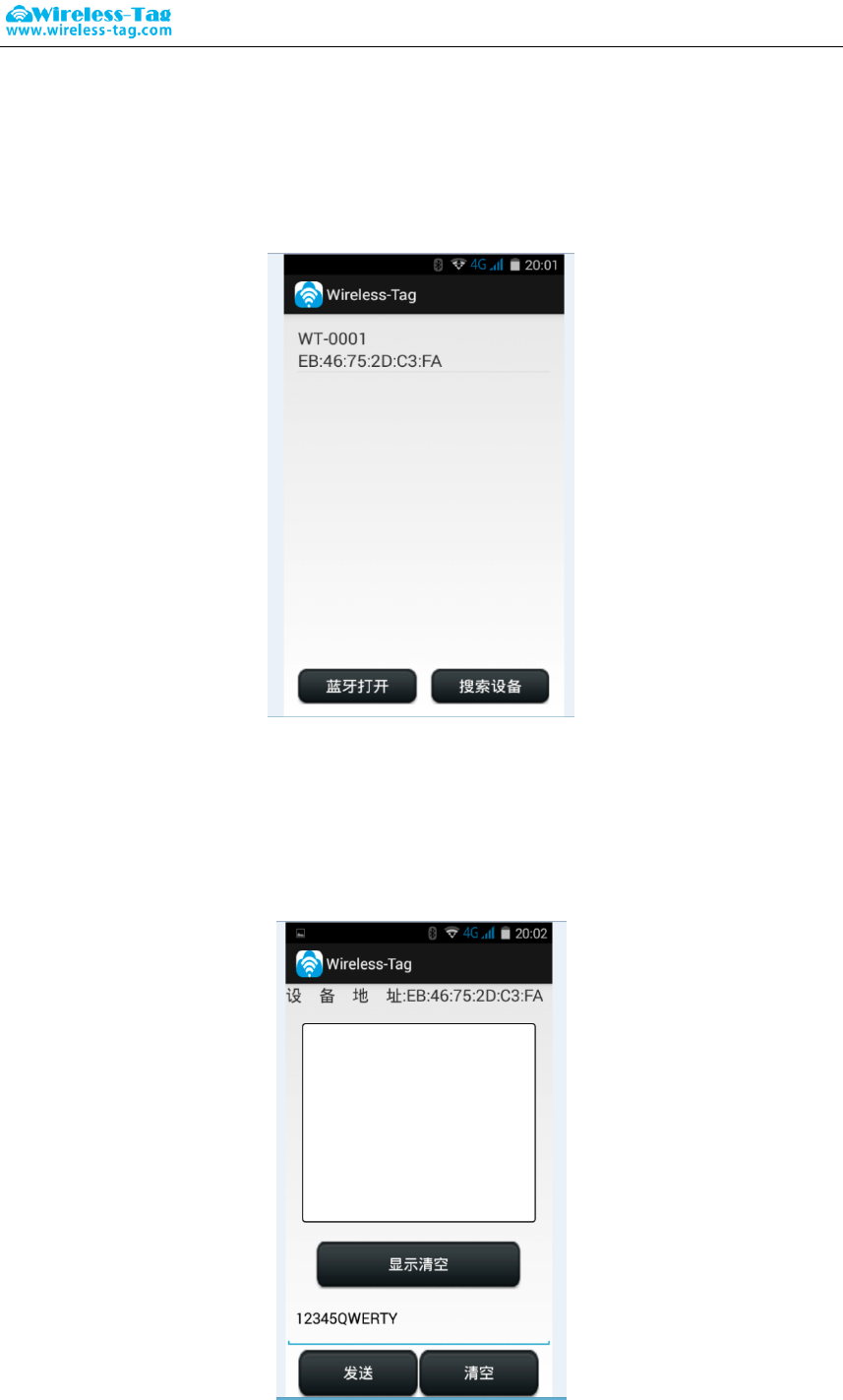
B. In the Android system (only Android 4.3 or above systems support Bluetooth 4.0) , you can
use our company self-made APP serial debugging tools:
Using APP tools to search for Bluetooth devices:
Connect with Bluetooth device, and input data in the serial transmission window, sends data
to Bluetooth device, the module will push the data sets to the serial port via DEMO-KIT after
receiving the data from LightBlue which can be displayed on the serial debugging tools by
PC side:
Forum: bbs.wireless-tag.com WT51822-S4AT
15 / 16
Wireless-Tag Technology www.wireless-tag.com technical@wireless-tag.com
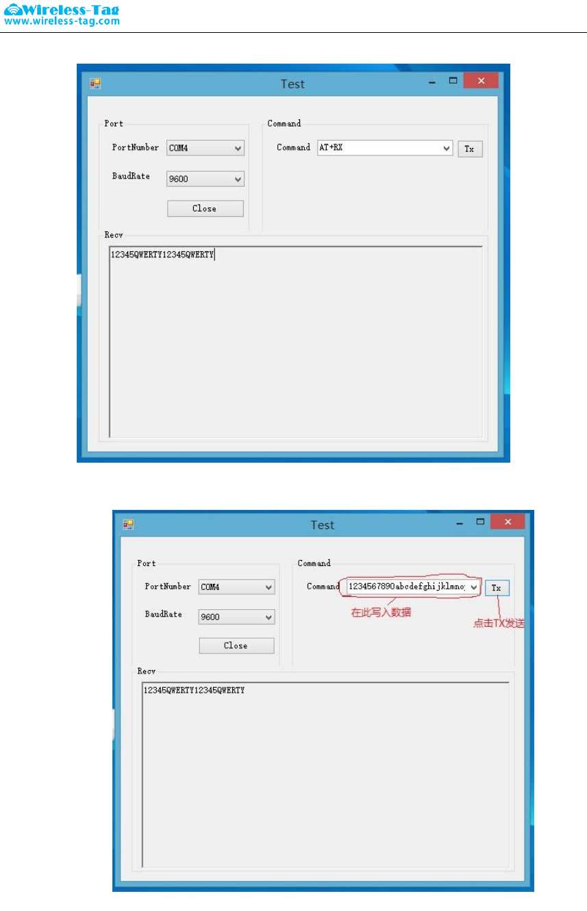
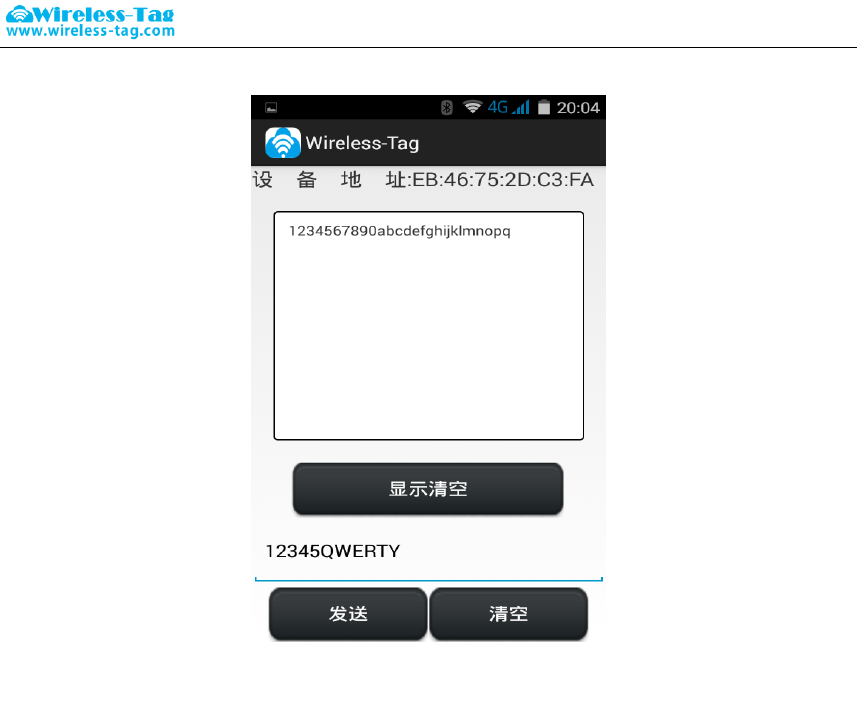
You can also use PC side debug tool to send data to the APP serial tool by module, APP display
window shows the data sent by Module
App serial tool received data and showed in the display window:
Forum: bbs.wireless-tag.com WT51822-S4AT
16 / 16
Wireless-Tag Technology www.wireless-tag.com technical@wireless-tag.com
It will create more comvenience and shorten the development period of bluetooth project by
using our DEMO-KIT tool and self made APP serial debugging tool
11. Appendix:
For more technical supports, please send e-mail to technical@wireless-tag.com
This module is intended for OEM integrator. The OEM integrator is still responsible for the FCC
compliance requirement of the end product which integrates this module.
20cm minimum distance has to be able to be maintained between the antenna and the users
for the host this module is integrated into. Under such configuration, the FCC radiation
exposure limits set forth for an population/uncontrolled environment can be satisfied.
Antenna used should be limited to same type with equal or lesser antenna gain.
According to FCC Part 15 Subpart C Section 15.212, the radio elements of the modular
transmitter must have their own power supply. However, due to there is no power supply for
this WIFI Module, this module is granted as a Limited Modular Approval. When this WIFI
Module is installed into the end product, a Class II Permissive Change or a New FCC ID
submission is required to ensure the full compliance of FCC relevant requirements.
FCC Caution: Any changes or modifications not expressly
approved by the party responsible for compliance could void the user's
authority to operate this equipment.
This device complies with Part 15 of the FCC Rules.
Operation is subject to the following two conditions: (1) This device may not
cause harmful interference, and (2) this device must accept any interference
received, including interference that may cause undesired operation.
This device and its antenna(s) must not be co-located or operating in conjunction
with any other antenna or transmitter.
15.105 Information to the user.
(b) For a Class B digital device or peripheral, the instructions furnished the
user shall include the following or similar statement, placed in a prominent
location in the text of the manual:
Note: This equipment has been tested and found to comply
with the limits for a Class B digital device, pursuant to part 15 of the FCC Rules.
These limits are designed to provide reasonable protection against harmful
interference in a residential installation. This equipment generates, uses and
can radiate radio frequency energy and, if not installed and used in
accordance with the instructions, may cause harmful interference to radio
communications. However, there is no guarantee that interference will not
occur in a particular installation. If this equipment does cause harmful
interference to radio or television reception, which can be determined by
turning the equipment off and on, the user is encouraged to try to correct the
interference by one or more of the following measures:
—Reorient or relocate the receiving antenna.
—Increase the separation between the equipment and receiver.
—Connect the equipment into an outlet on a circuit different from that to which
the receiver is connected.
—Consult the dealer or an experienced radio/TV technician for help.
1.This LMA does not have RF shielding and is tested and approved as standalone
configuration, additional evaluation may be required for any system integrated
this radio module.
2.The modular transmitter doesn’t have its own power supply regulation,
it’s provided by host.
Radiation Exposure Statement:
This equipment complies with FCC radiation exposure limits set forth for an
uncontrolled environment.
This transmitter must not be co-located or operating in conjunction with any other
antenna or transmitter.
The availability of some specific channels and/or operational frequency bands
are country dependent and are firmware programmed at the factory to match
the intended destination.
The firmware setting is not accessible by the end user.
The final end product must be labelled in a visible area with the following:
“Contains Transmitter Module 2AFOSWT51822”