User Manual
V-JETm2 / JET-R
User’s Manual
1
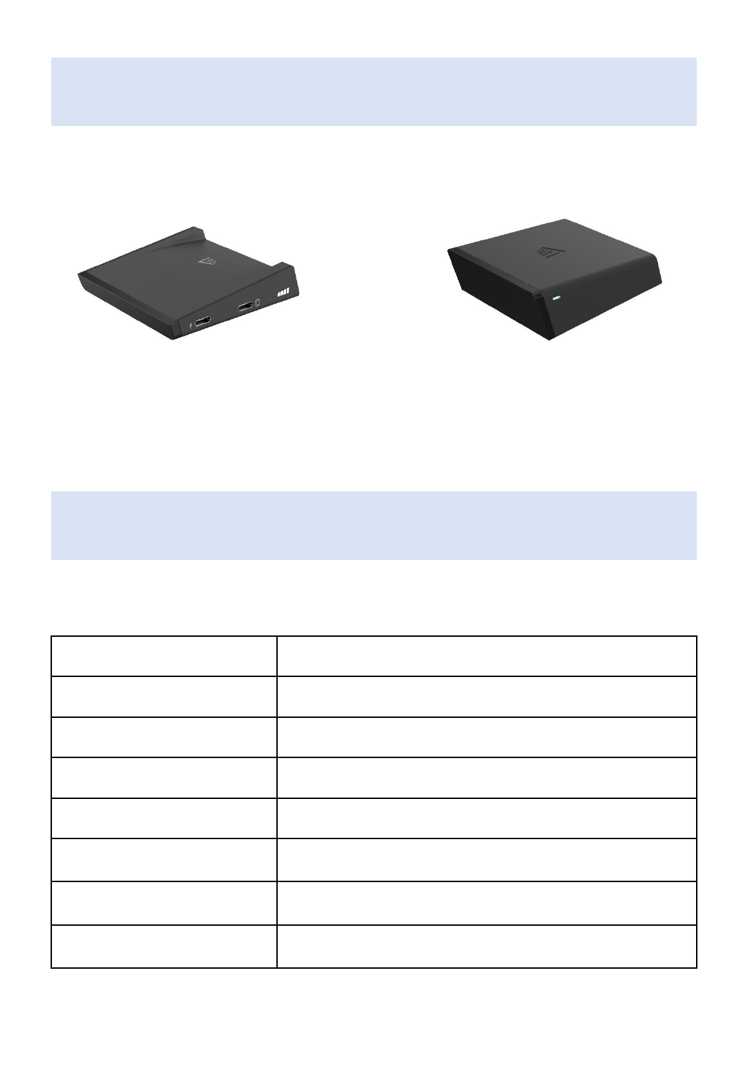
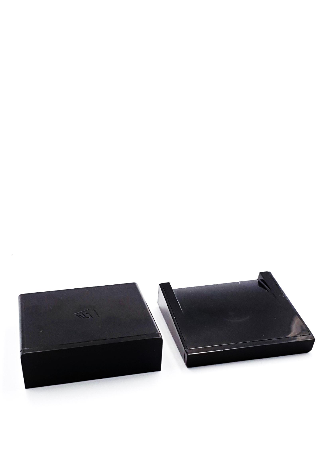
Package Contents
Transmitter Receiver
Specifications
Product Usage
Wireless Video Streaming
Connector Type
HDMI / USB-C
Operating Frequency Range
57GHz ~ 64GHz
Wireless Distance
Max. 10 meters (in Line of Sight)
Max. Resolution
4K/30Hz (3840 x 2160)
Temperature
Operating Temp: 0 °C ~ 50 °C
Storage Temp: -20 °C ~ 70 °C
Dimensions
(W x D x H)
Transmitter: 70 x 72 x 18 (mm)
Receiver: 70 x 72 x 24 (mm)
Power Input
Transmitter: DC 5V / 900mA
Receiver: DC5 V / 1A
2
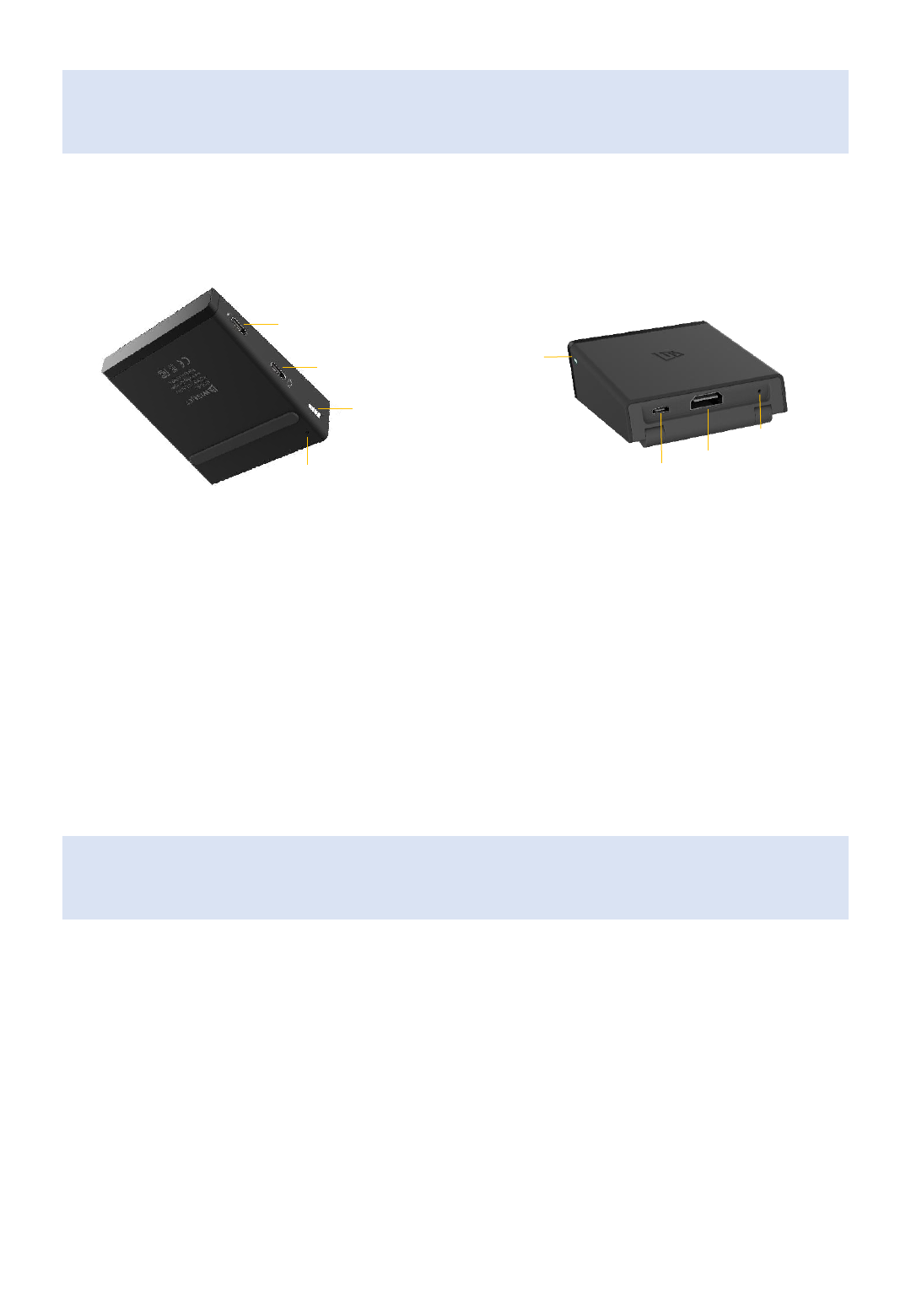
Panel Layout
Transmitter Receiver
ⓐ
Charging Port (USB-C)
ⓑ
Source Device Connecting Port (USB-C)
ⓒ
LED Indicator
ⓓ
Re-set Button
ⓐ
ⓑ
ⓒ
ⓓ ⓐ
ⓑ
ⓒ
ⓓ
ⓐ
Display Device Connecting Port (HDMI)
ⓑ
Power Input (micro USB)
ⓒ
Re-set Button
ⓓ
LED Indicator
3
LED Indicators
LED Off
The unit is in sleep mode or turned off
LED Slow Blink
The unit is on but not paired
LED Fast Blink
The unit is trying to be paired
LED On
The both units are paired and wirelessly connected
Transmitter LED Indicator
(wireless connection status)
2 LED lights: Weak / 3 LED lights: Good / 4 LED lights: Strong
*Reset – If re-pairing is required, hold down the reset button of the transmitter until the LED light
turns off then release it. Also, reset the receiver in the same way.
Installation
① Receiver Installation
1. Turn on your display device
2. Connect the receiver and the display device using the HDMI+USB cable provided
- If the USB power from the display device is not sufficient, please use a separate 5V power adapter
3. Check if input mode of the display device is set to the HDMI port connected with the receiver
4. Make sure that the receiver faces to the transmitter
② Transmitter Installation
1. Turn on your source device
2. Connect the transmitter and the source device using the USB-C cable provided
3. Make sure that the transmitter faces to the receiver
* You can charge the source device trough the charging port on the transmitter when its battery is low
4
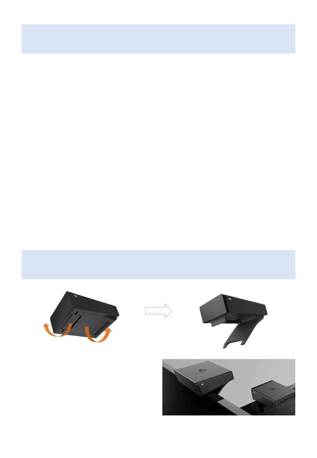
How to mount Receiver on TV
Pull off the brackets
at the bottom of the receiver
Receiver mounted on the top of TV

Federal Communication Commissi
on Interference Statement
• This device complies with Part 15 of the FCC Rules. Operation is subject
to the following two conditions: (1) This device may not cause harmful interfer
ence, and (2) this device must accept any interference received, including inte
rference that may cause undesired operation.
•
• This equipment has been tested and found to comply with the limits for
a Class B digital device, pursuant to Part 15 of the FCC Rules. These limits are
designed to provide reasonable protection against harmful interference in a re
sidential installation. This equipment generates, uses and can radiate radio fre
quency energy and, if not installed and used in accordance with the instructio
ns, may cause harmful interference to radio communications. However, there
is no guarantee that interference will not occur in a particular installation. If t
his equipment does cause harmful interference to radio or television receptio
n, which can be determined by turning the equipment off and on, the user is e
ncouraged to try to correct the interference by one of the following measures:
•
• - Reorient or relocate the receiving antenna.
• - Increase the separation between the equipment and receiver.
• - Connect the equipment into an outlet on a circuit different fro
m that
• to which the receiver is connected.
• - Consult the dealer or an experienced radio/TV technician for h
elp.
•
• FCC Caution: Any changes or modifications not expressly approved by t
he party responsible for compliance could void the user's authority to operate
this equipment.
•
• This transmitter must not be co-located or operating in conjunction wit
h any other antenna or transmitter.
5

• Radiation Exposure Statement:
• This equipment complies with FCC radiation exposure limits set f
orth for an uncontrolled environment. This equipment should be install
ed and operated with minimum distance 20cm between the radiator &
your body.
•
• This device is intended only for OEM integrators under the follow
ing conditions:
•1) The antenna must be installed such that 20 cm is maintained bet
ween the antenna and users, and
•2) The transmitter module may not be co-located with any other tra
nsmitter or antenna.
•As long as 2 conditions above are met, further transmitter test will not
be required. However, the OEM integrator is still responsible for testing
their end-product for any additional compliance requirements required
with this module installed
•IMPORTANT NOTE: In the event that these conditions can not be met (f
or example certain laptop configurations or co-location with another tra
nsmitter), then the FCC authorization is no longer considered valid and t
he FCC ID can not be used on the final product. In these circumstances,
the OEM integrator will be responsible for re-evaluating the end produc
t (including the transmitter) and obtaining a separate FCC authorization.
•End Product Labeling
•This transmitter module is authorized only for use in device where the a
ntenna may be installed such that 20 cm may be maintained between t
he antenna and users. The final end product must be labeled in a visible
area with the following: “Contains FCC ID: 2ALI9V-VJETM2”. The grantee
's FCC ID can be used only when all FCC compliance requirements are m
et.
•Manual Information To the End User
•The OEM integrator has to be aware not to provide information to the e
nd user regarding how to install or remove this RF module in the user’s
manual of the end product which integrates this module.
•The end user manual shall include all required regulatory information/
warning as show in this manual.
6