WIZNET WIZFI250 WiFi Module User Manual WM N BM 14 datasheet V21 20130710
WIZNET Co., LTD. WiFi Module WM N BM 14 datasheet V21 20130710
UserManual.wiki
>
WIZNET
>
WIZFI250 User Manual
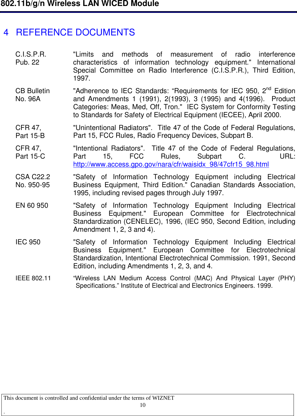
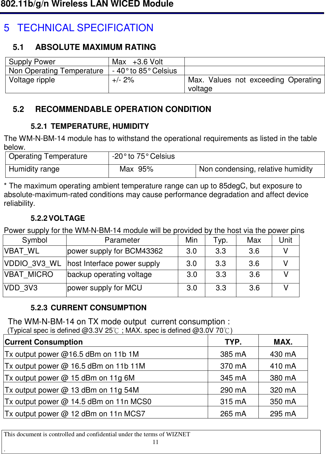
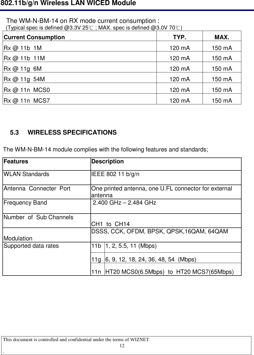
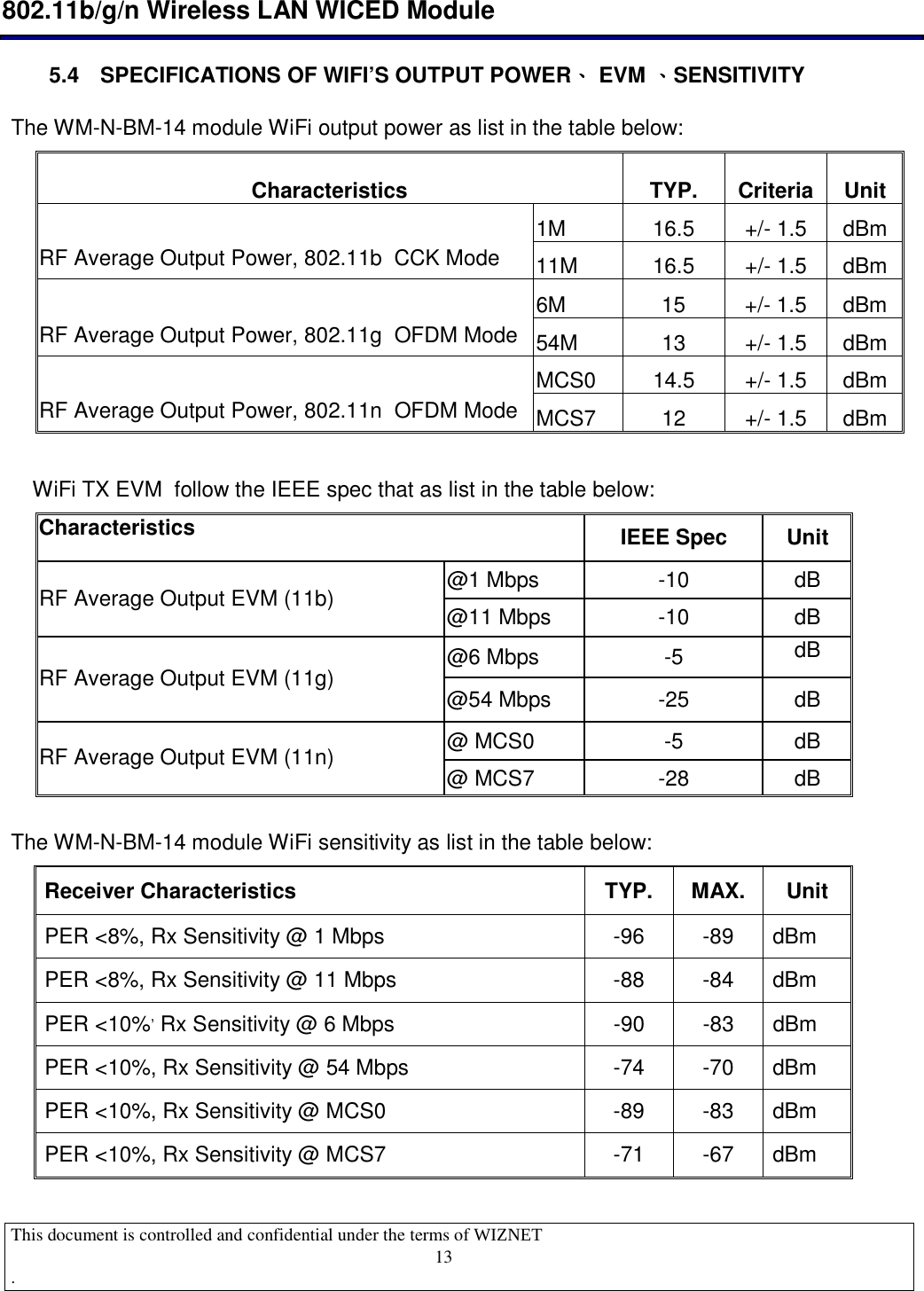
USERS MANUAL
Navigation menu
Upload a User Manual
Namespaces
Wiki Guide
HTML
PDF
Info
Views
User Manual
Discussion / Help
Navigation
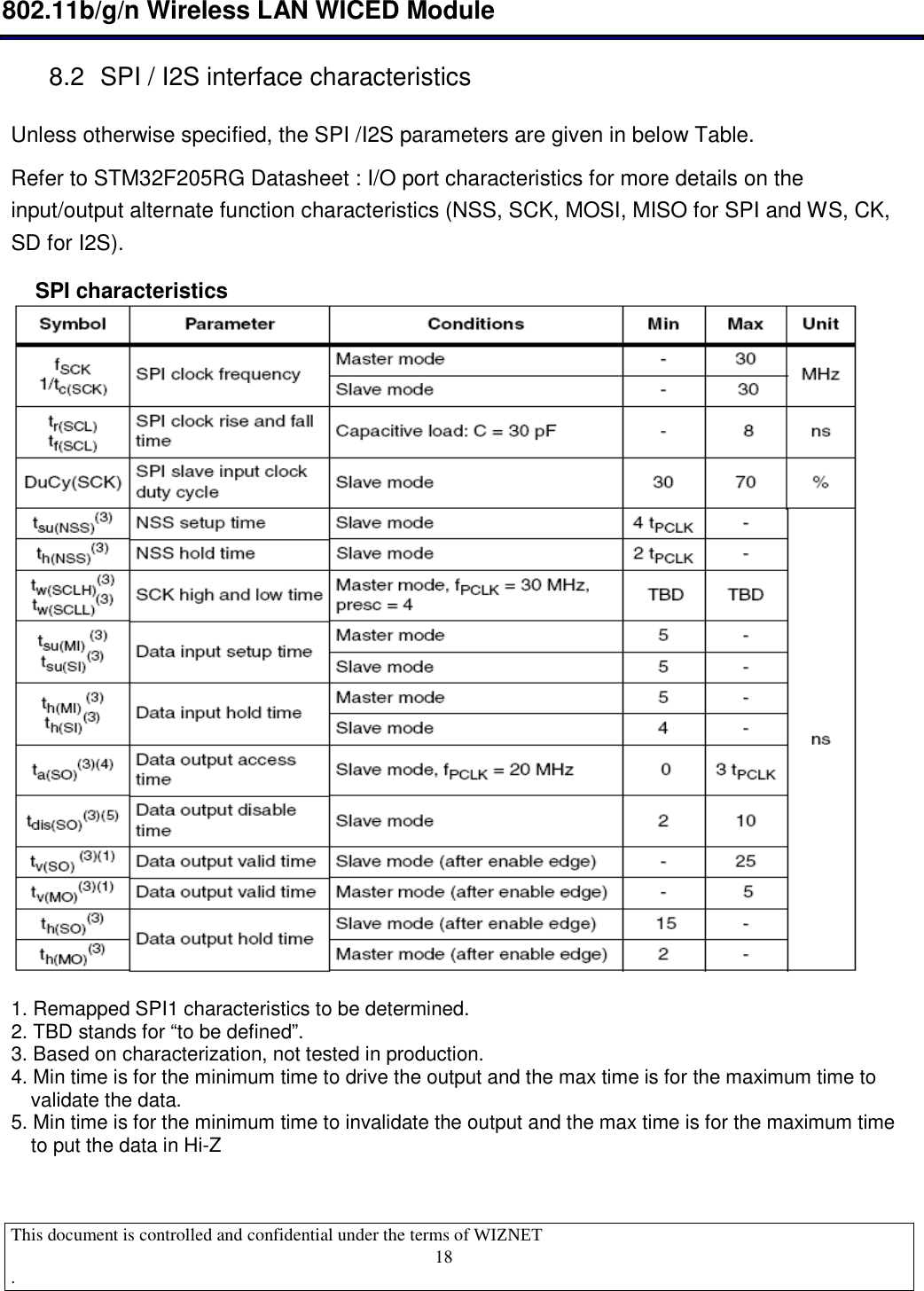
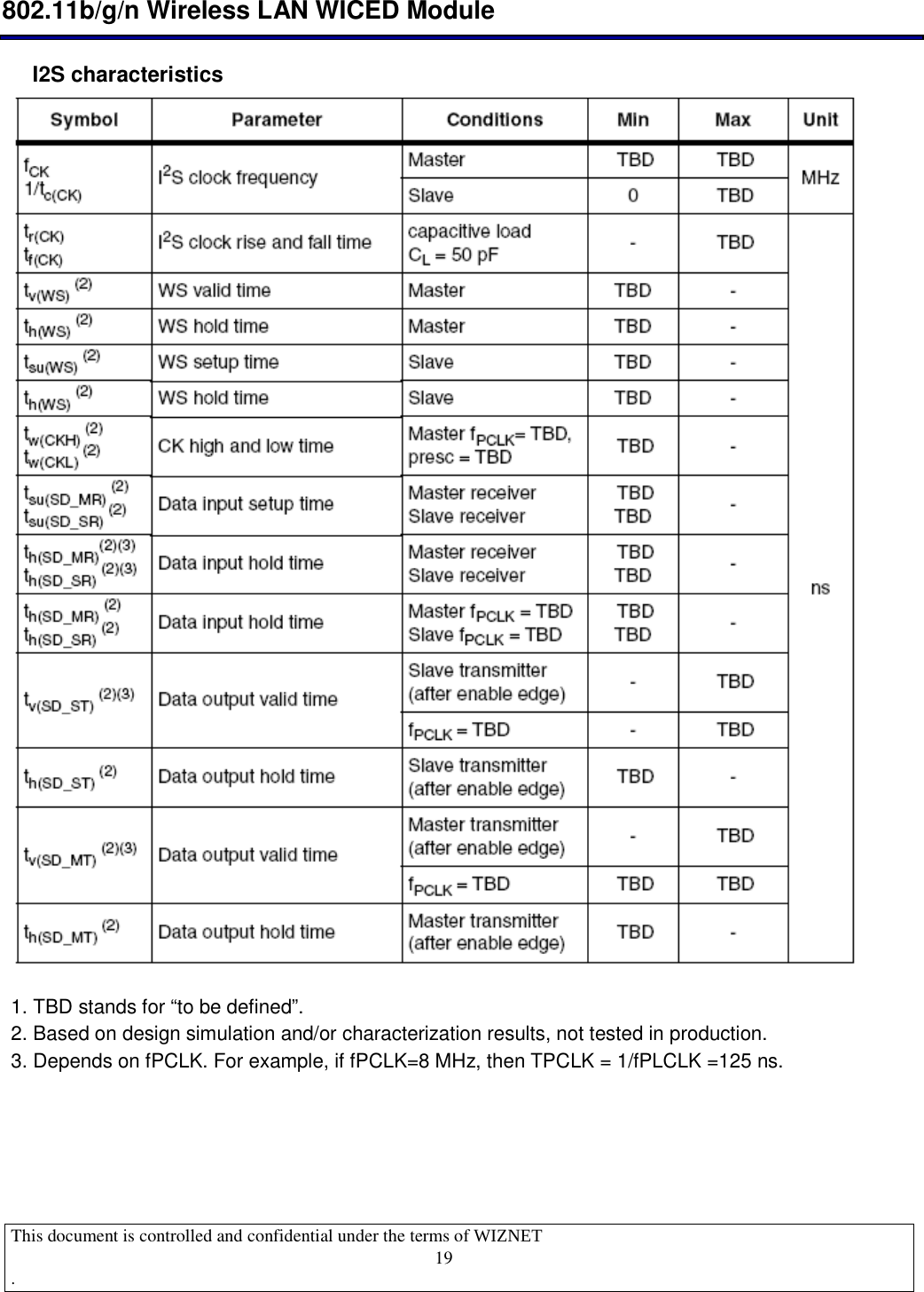
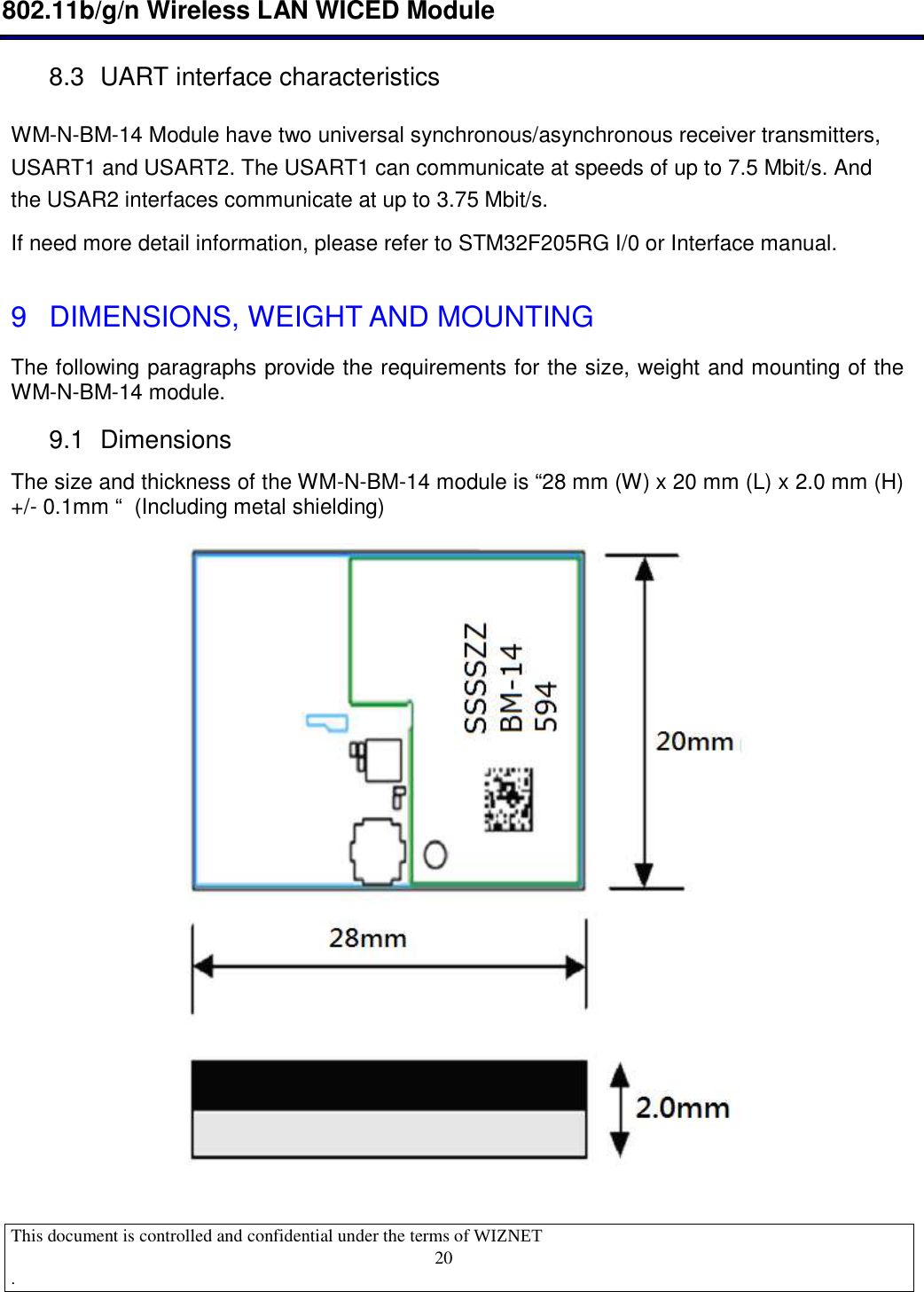
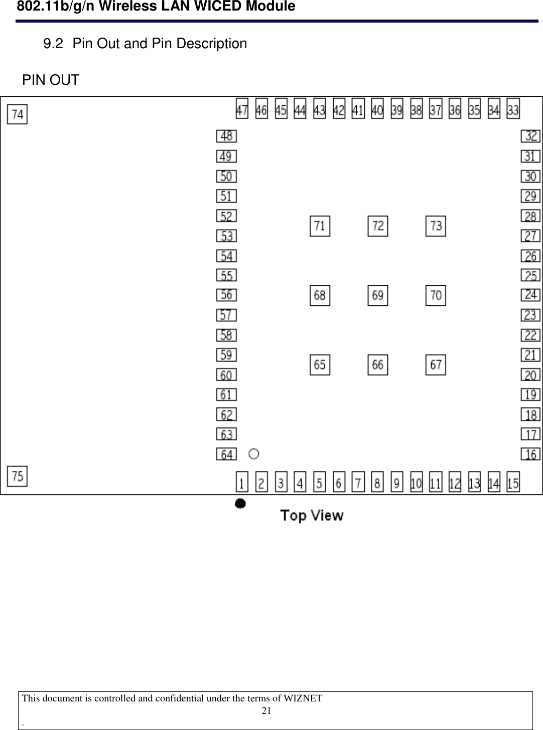
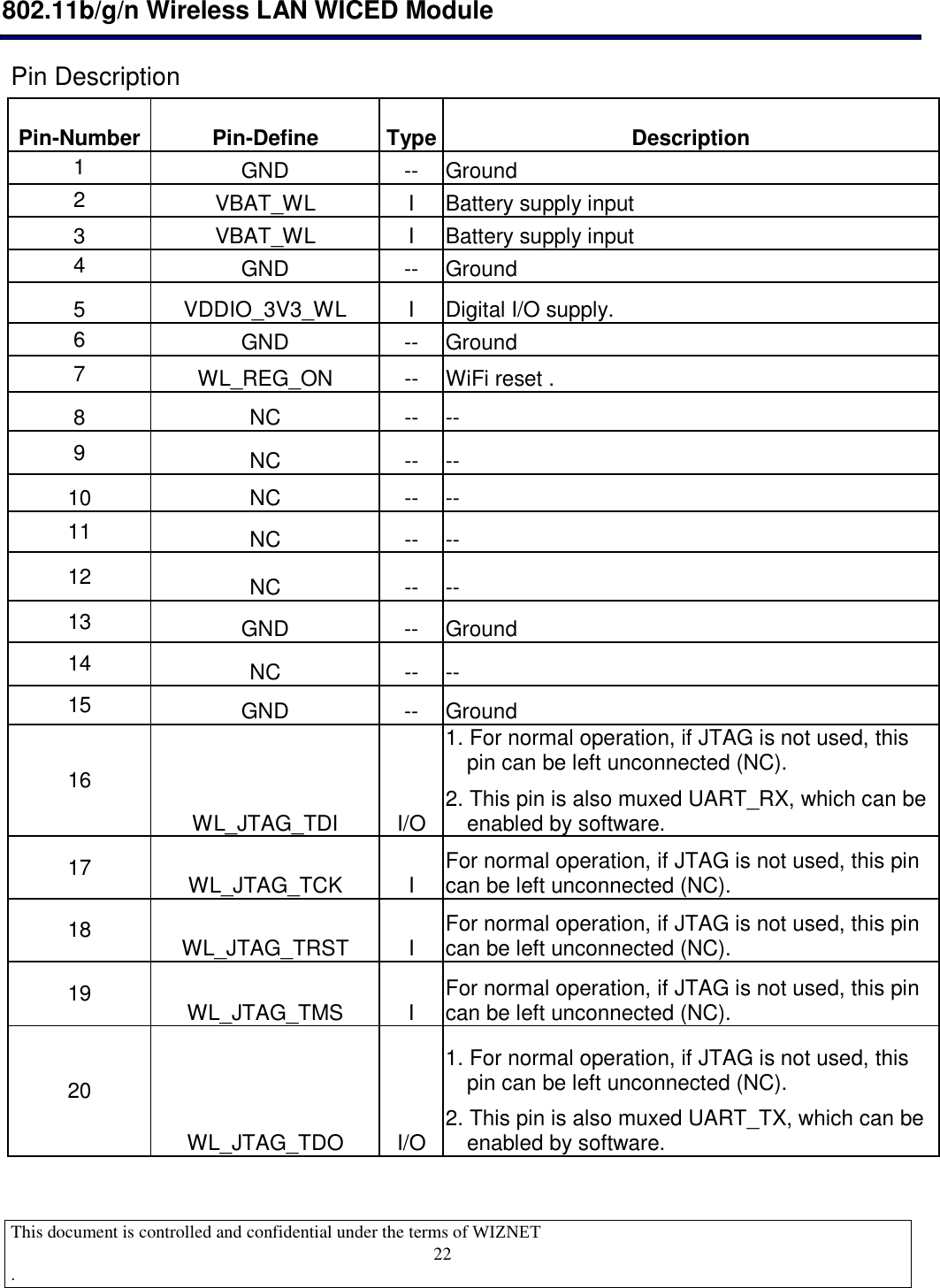
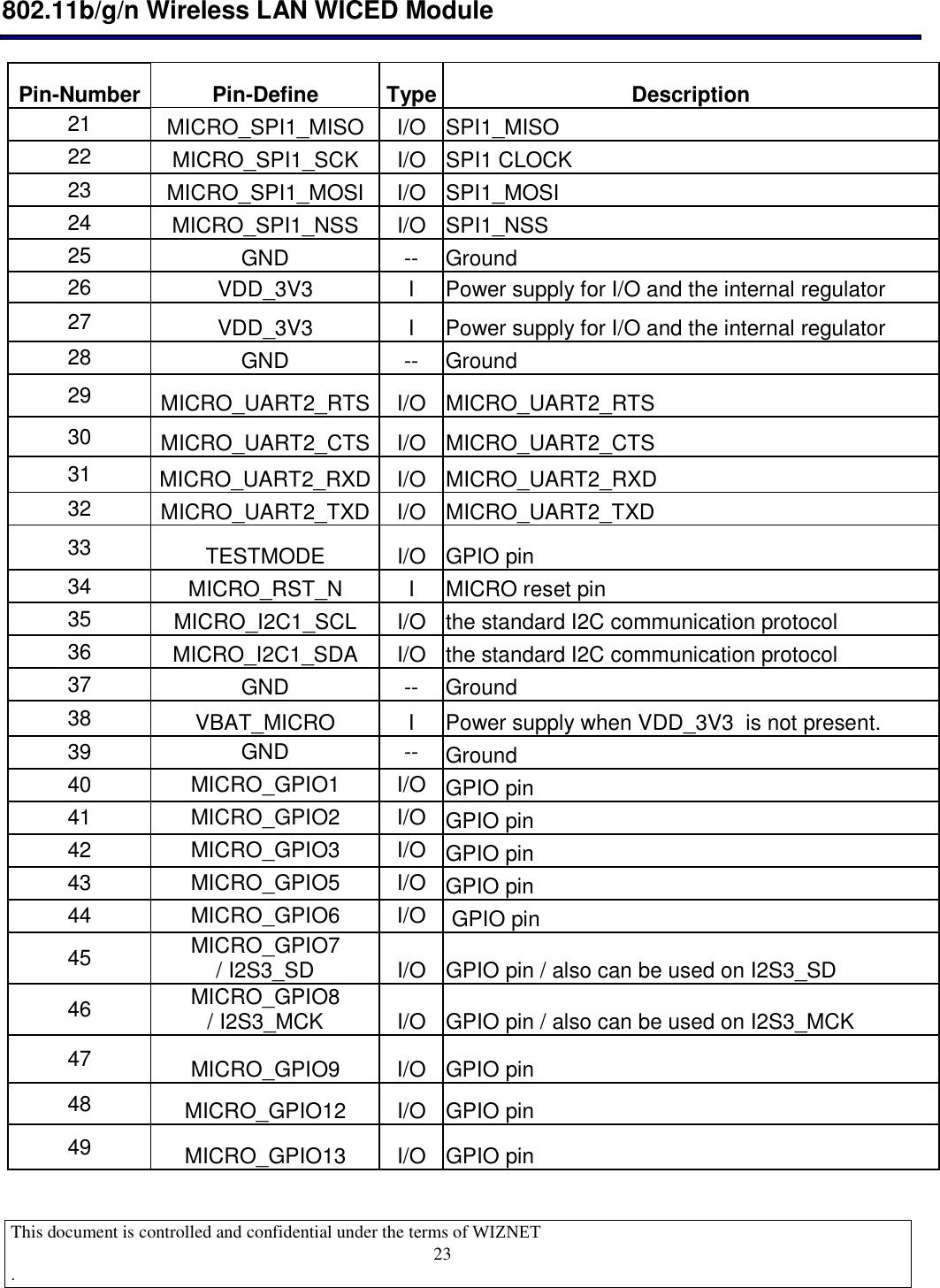
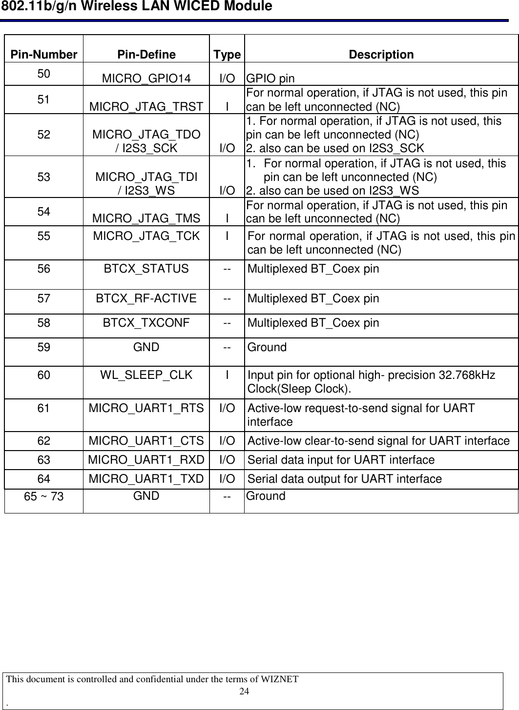
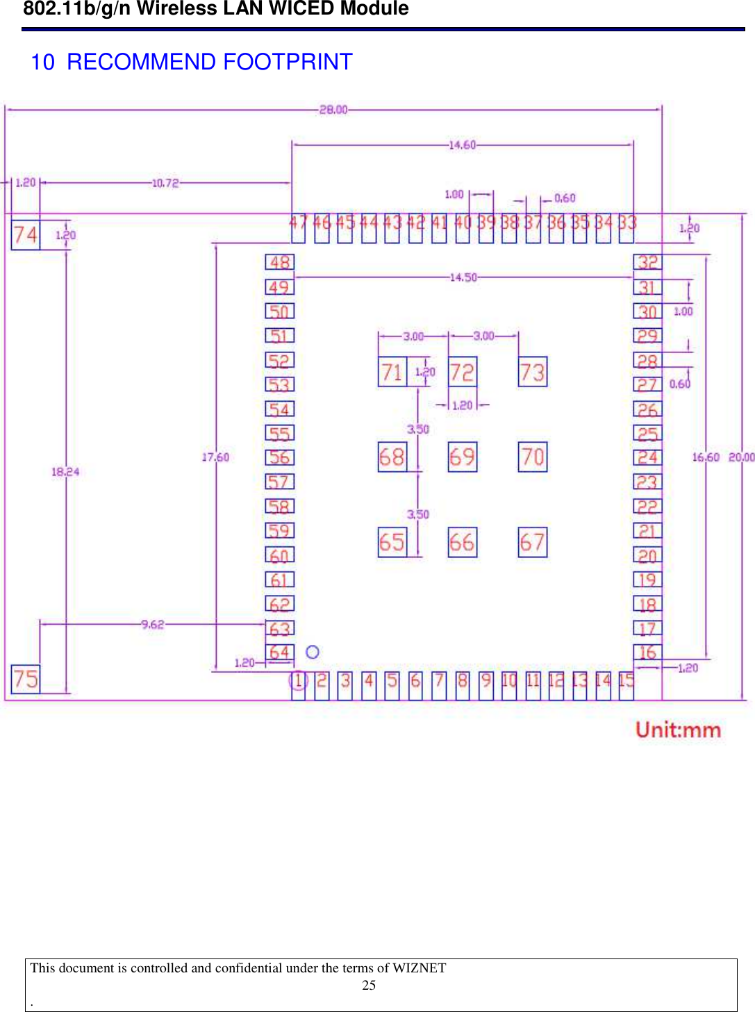
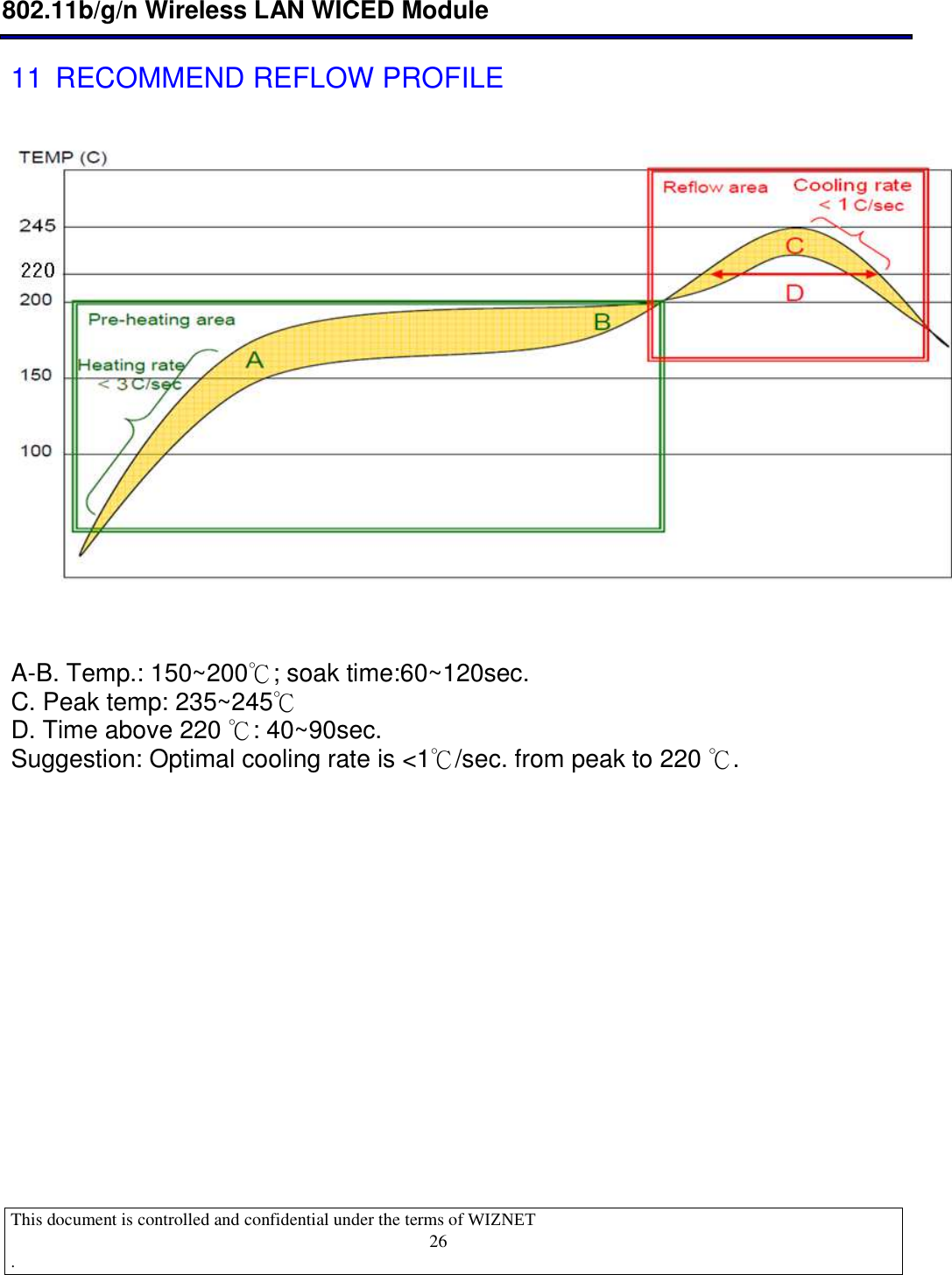
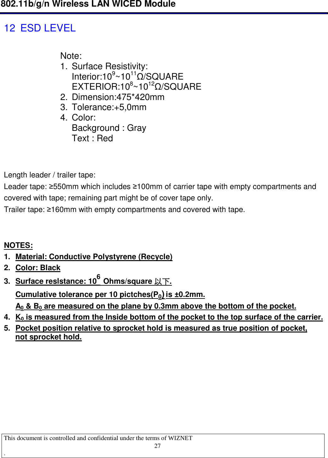
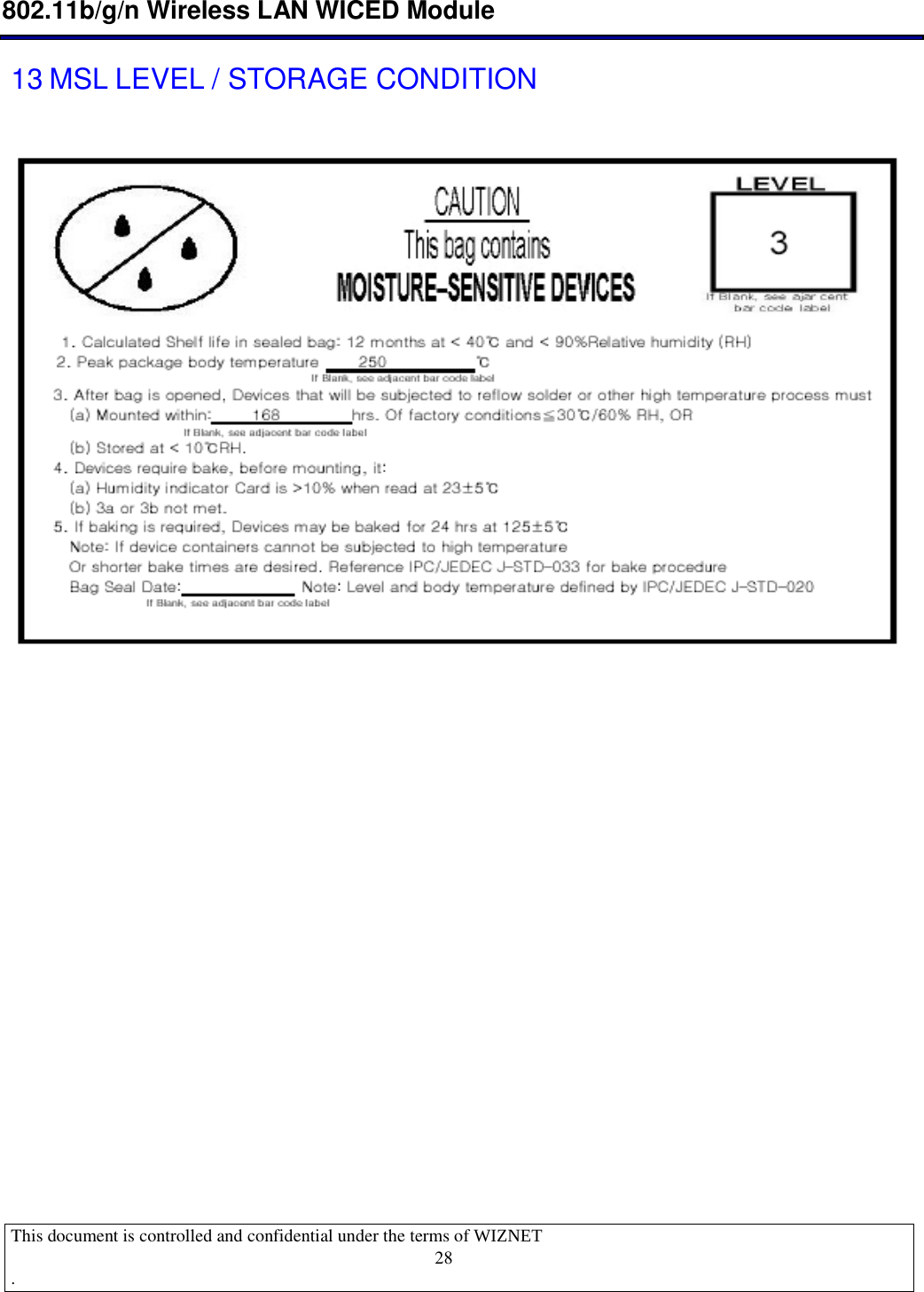
![[鍵入文字] This document is controlled and confidential under the terms of WIZNET . 1 WizFi250 User Manual Datasheet July 10 2013 Rev 2.1 802.11b/g/n WICED Module (WM-N-BM-14)](https://usermanual.wiki/WIZNET/WIZFI250/User-Guide-2227270-Page-1.png)