WIZNET WIZFI250 WiFi Module User Manual WM N BM 14 datasheet V21 20130710
WIZNET Co., LTD. WiFi Module WM N BM 14 datasheet V21 20130710
WIZNET >
USERS MANUAL
[鍵入文字]
This document is controlled and confidential under the terms of WIZNET
. 1
WizFi250
User Manual
Datasheet July 10 2013 Rev 2.1
802.11b/g/n WICED Module (WM-N-BM-14)

FCC Statement
NOTICE;
1. The RF module limited to OEM installation ONLY.
The OEM integrator is responsible for the compliance to all the rules that apply to the
product into which this certified RF module is integrated.
2. This device complies with part 15 of the FCC Rules. Operation is subject to the following
two conditions: (1) This device may not cause harmful interference, and (2) this device must
accept any interference received, including interference that may cause undesired operation.
3. This equipment has been tested and found to comply with the limits for a Class B digital
device, pursuant to part 15 of the FCC Rules. These limits are designed to provide
reasonable protection against harmful interference in a residential installation.
This equipment generates uses and can radiate radio frequency energy and, if not installed
and used in accordance with the instructions, may cause harmful interference to radio
communications. However, there is no guarantee that interference will not occur in a
particular installation. If this equipment does cause harmful interference to radio or television
reception, which can be determined by turning the equipment off and on, the user is
encouraged to try to correct the interference by one or more of the following measures:
l Reorient or relocate the receiving antenna.
l Increase the separation between the equipment and receiver.
l Connect the equipment into an outlet on a circuit different from that to which the
receiver is connected.
l Consult the dealer or an experienced radio/TV technician for help.
FCC Caution
Any changes or modifications not expressly approved by the party responsible for compliance could
void the user's authority to operate this equipment. This transmitter must not be co-located or
operating in conjunction with any other antenna or transmitter.
Radiation Exposure Statement
This equipment complies with FCC radiation exposure limits set forth for an uncontrolled
environment. This equipment should be installed and operated with minimum distance 20cm between
the radiator & your body.
This device is intended only for OEM integrators under the following conditions:
The antenna must be installed such that 20 cm is maintained between the antenna and users, and The
transmitter module may not be co-located with any other transmitter or antenna. As long as 2
conditions above are met, further transmitter test will not be required. However, the OEM integrator is
still responsible for testing their end-product for any additional compliance requirements required
with this module installed.
This document is controlled and confidential under the terms of WIZNET
. 2

IMPORTANT NOTE:
In the event that these conditions cannot be met (for example certain laptop configurations or co-
location with another transmitter), then the FCC authorization is no longer considered valid and the
FCC ID cannot be used on the final product. In these circumstances, the OEM integrator will be
responsible for re-evaluating the end product (including the transmitter) and obtaining a separate FCC
authorization.
End Product Labeling
This transmitter module is authorized only for use in device where the antenna may be installed such
that 20 cm may be maintained between the antenna and users. The final end product must be labeled
in a visible area with the following:
“Contains FCC ID: XR2WIZFI250”.
The grantee's FCC ID can be used only when all FCC/ IC compliance requirements are met.
Manual Information To the End User
The OEM integrator has to be aware not to provide information to the end user regarding how to
install or remove this RF module in the user's manual of the end product which integrates this module.
The end user manual shall include all required regulatory information/warning as show in this manual.
This document is controlled and confidential under the terms of WIZNET
. 3
802.11b/g/n Wireless LAN WICED Module
This document is controlled and confidential under the terms of WIZNET
. 4
Introduction
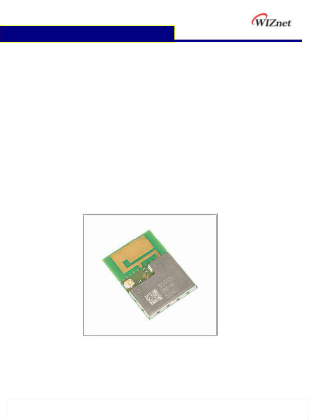
The WM-N-BM-14 wireless WICED module which is a
small size module and consists of a Broadcom
BCM43362 single-chip, a ST STM32F205RG MCU, and
a 2.4G antenna. The WM-N-BM-14 provides for the
highest-level integration, featuring 802.11b/g and
802.11n.
It includes a 2.4 GHz WLAN CMOS power amplifier
(PA) that meets the output power requirements of most
handheld systems. An optional external low-noise
amplifier (LNA) and external PA are also supported.
Along with the integrated power amplifier, the WM-N-
BM-14 also includes integrated transmit and receive
baluns, further reducing the overall solution cost.
The small size & low profile physical design make it
easier for system design to enable high performance
wireless connectivity without space constrain. This
multi- functionality and board to board physical interface
provides SPI/I2C/I2S/UART interface options.
Hardware WAPI acceleration engine, AES, TKIP, WPA
and WPA2 are supported to provide the latest security
requirement on your network.
For the software and driver development, USI provides
extensive technical document and reference software
code for the system integration under the agreement of
Broadcom International Ltd.
Hardware evaluation kit and development utilities will be
released base on listed OS and processors to OEM
customers.
Features
BCM43362 Wi-Fi
Single band 2.4GHz IEEE 802.11b/g/n
Supports wireless data rates up to 65Mbit/s
Integrated RF power amplifier
STM32F205RGY6 Microprocessor
ARM 32-bit Cortex-M3 CPU
CPU frequency up to 120MHz
1 MB Flash memory
128 kB SRAM
Low-power sleep, standby and stop modes
Extend one 8Mbit Flash memory
WM-N-BM-14 Wireless Module
Featuring integrated IEEE 802.11 b/g/n
Supports per packet Rx Antenna diversity
Low power consumption & excellent power
management performance extend battery life.
Small size suitable for low volume system
integration.
Easy for integration into mobile and handheld
device with flexible system configuration.
2.412-2.484 GHz two SKUs for worldwide
market.
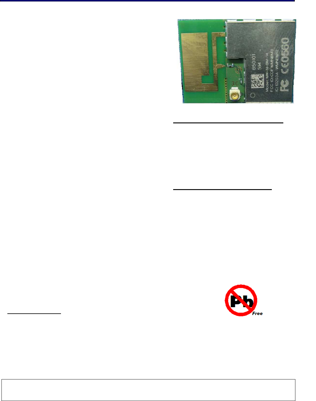
Lead Free design which supporting Green
design requirement, RoHS Compliance.
Device Package
28x20 mm

802.11b/g/n Wireless LAN WICED Module
This document is controlled and confidential under the terms of WIZNET
. 5
Change Sheet
Rev.
Date
Description of change
Approval & Date
Page Par Change(s)
1.1 01/15/13 All All Initial Release Scarrie/Kevin
2 Update module picture in Introduction
12 5.5 Add power table of band eange-regulatory for
US/Canada and EU market
2.1
07/10/13
24 10 Update recommend footprint dimension
Scarrie/Kevin

802.11b/g/n Wireless LAN WICED Module
This document is controlled and confidential under the terms of WIZNET
. 6
TABLE OF CONTENTS
1 EXECUTIVE SUMMARY................................................................................................................ 7
2 BLOCK DIAGRAM DESCRIPTION ............................................................................................... 8
3 DELIVERABLES .............................................................................................................................. 9
4 REFERENCE DOCUMENTS......................................................................................................... 10
5 TECHNICAL SPECIFICATION......................................................................................................11
5.1 ABSOLUTE MAXIMUM RATING............................................................................................ 11
5.2 RECOMMENDABLE OPERATION CONDITION.................................................................... 11
5.2.1 TEMPERATURE, HUMIDITY ......................................................................................... 11
5.2.2 VOLTAGE ...................................................................................................................... 11
5.2.3 CURRENT CONSUMPTION .......................................................................................... 11
5.3 WIRELESS SPECIFICATIONS............................................................................................ 12
5.4 SPECIFICATIONS OF WIFI’S OUTPUT POWER、 EVM 、SENSITIVITY.......................... 13
5.5 SPECIFICATIONS OF WIFI’S BAND EANGE-REGULATORY POWERTABLE FOR
US/CANADA AND EU MARKET...................................................................................................... 14
6 FLASH MEMORY .......................................................................................................................... 15
6.1 MCU EMBEDDED FLASH MEMORY................................................................................... 15
6.2 MODULE INTERNAL MEMORY FLASH.............................................................................. 15
7 I/O PORT CHARACTERISTICS.................................................................................................. 16
8 COMMUNICATIONS INTERFACE ............................................................................................. 17
9 DIMENSIONS, WEIGHT AND MOUNTING .............................................................................. 20
10 RECOMMEND FOOTPRINT ................................................................................................... 25
11 RECOMMEND REFLOW PROFILE ....................................................................................... 26
12 ESD LEVEL................................................................................................................................. 27
13 MSL LEVEL / STORAGE CONDITION.................................................................................. 28

802.11b/g/n Wireless LAN WICED Module
This document is controlled and confidential under the terms of WIZNET
. 7
1 EXECUTIVE SUMMARY
The WM-N-BM-14 module - is one of the product families in UG’s product offering, targeting for
system integration requiring a smaller form factor. It also provides the standard migration to high
data rate to UG’s current SIP customers.
The purpose of this document is to define the product specification for 802.11b/g/n WiFi
module WM-N-BM-14. All the data in this document is based on Broadcom 43362
datasheet, STM32F205 datasheet and other documents provided from Broadcom and
ST . The data will be updated after implementing the measurement of the module.

802.11b/g/n Wireless LAN WICED Module
This document is controlled and confidential under the terms of WIZNET
. 8
2 BLOCK DIAGRAM DESCRITPION
The WM-N-BM-14 module is designed based on Broadcom 43362 chipset and ST MCU
solution. It supports generic SPI, UART, I2S, I2C interface to connect the WLAN to the host
processor.

802.11b/g/n Wireless LAN WICED Module
This document is controlled and confidential under the terms of WIZNET
. 9
3 DELIVERABLES
The following products and software will be part of the product.
WM-N-BM-14 Module with packaging
Evaluation kits (with SPI / UART/ JTAG interface)
Software utility which supporting customer for integration, performance test and
homologation. Capable of testing, loading (firmware) and configuring (MAC, CIS) for
the WM-N-BM-14 module.
Unit Test / Qualification report
Product Specifications.
Agency certification pre-test report base on adapter boards

10
802.11b/g/n Wireless LAN WICED Module
This document is controlled and confidential under the terms of WIZNET
.
4 REFERENCE DOCUMENTS
C.I.S.P.R.
Pub. 22 "Limits and methods of measurement of radio interference
characteristics of information technology equipment." International
Special Committee on Radio Interference (C.I.S.P.R.), Third Edition,
1997.
CB Bulletin
No. 96A "Adherence to IEC Standards: “Requirements for IEC 950, 2
nd
Edition
and Amendments 1 (1991), 2(1993), 3 (1995) and 4(1996). Product
Categories: Meas, Med, Off, Tron." IEC System for Conformity Testing
to Standards for Safety of Electrical Equipment (IECEE), April 2000.
CFR 47,
Part 15-B "Unintentional Radiators". Title 47 of the Code of Federal Regulations,
Part 15, FCC Rules, Radio Frequency Devices, Subpart B.
CFR 47,
Part 15-C "Intentional Radiators". Title 47 of the Code of Federal Regulations,
Part 15, FCC Rules, Subpart C. URL:
http://www.access.gpo.gov/nara/cfr/waisidx_98/47cfr15_98.html
CSA C22.2
No. 950-95 "Safety of Information Technology Equipment including Electrical
Business Equipment, Third Edition." Canadian Standards Association,
1995, including revised pages through July 1997.
EN 60 950 "Safety of Information Technology Equipment Including Electrical
Business Equipment." European Committee for Electrotechnical
Standardization (CENELEC), 1996, (IEC 950, Second Edition, including
Amendment 1, 2, 3 and 4).
IEC 950 "Safety of Information Technology Equipment Including Electrical
Business Equipment." European Committee for Electrotechnical
Standardization, Intentional Electrotechnical Commission. 1991, Second
Edition, including Amendments 1, 2, 3, and 4.
IEEE 802.11 “Wireless LAN Medium Access Control (MAC) And Physical Layer (PHY)
Specifications.” Institute of Electrical and Electronics Engineers. 1999.
11
802.11b/g/n Wireless LAN WICED Module
This document is controlled and confidential under the terms of WIZNET
.
5 TECHNICAL SPECIFICATION
5.1 ABSOLUTE MAXIMUM RATING
Supply Power Max +3.6 Volt
Non Operating Temperature - 40° to 85° Celsius
Voltage ripple +/- 2% Max. Values not exceeding Operating
voltage
5.2 RECOMMENDABLE OPERATION CONDITION
5.2.1 TEMPERATURE, HUMIDITY
The WM-N-BM-14 module has to withstand the operational requirements as listed in the table
below.
Operating Temperature -20° to 75° Celsius
Humidity range Max 95% Non condensing, relative humidity
* The maximum operating ambient temperature range can up to 85degC, but exposure to
absolute-maximum-rated conditions may cause performance degradation and affect device
reliability.
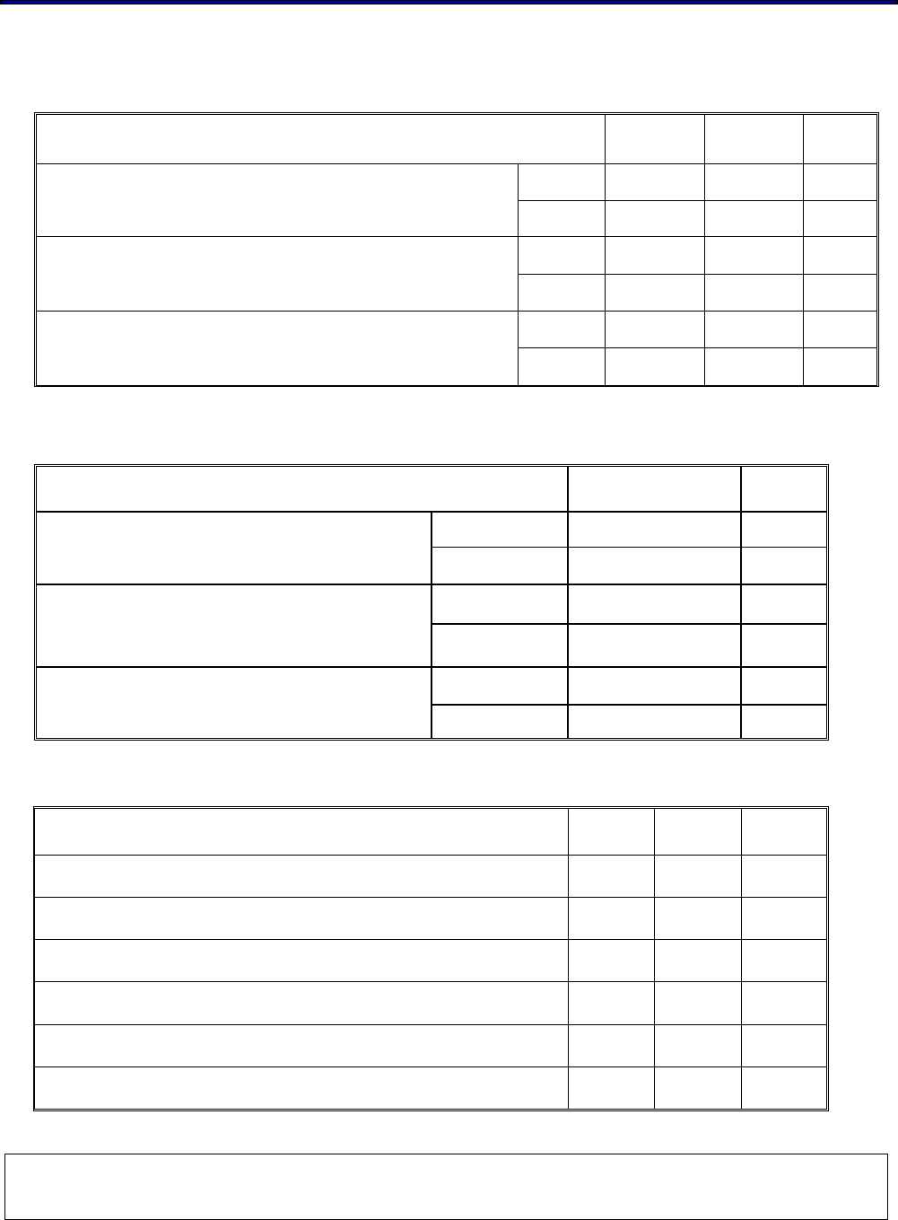
5.2.2 VOLTAGE
Power supply for the WM-N-BM-14 module will be provided by the host via the power pins
Symbol Parameter Min Typ. Max Unit
VBAT_WL power supply for BCM43362 3.0 3.3 3.6 V
VDDIO_3V3_WL host Interface power supply 3.0 3.3 3.6 V
VBAT_MICRO backup operating voltage 3.0 3.3 3.6 V
VDD_3V3 power supply for MCU 3.0 3.3 3.6 V
5.2.3 CURRENT CONSUMPTION
The WM-N-BM-14 on TX mode output current consumption :
(Typical spec is defined @3.3V 25℃ ; MAX. spec is defined @3.0V 70℃)
Current Consumption TYP. MAX.
Tx output power @16.5 dBm on 11b 1M 385 mA 430 mA
Tx output power @ 16.5 dBm on 11b 11M 370 mA 410 mA
Tx output power @ 15 dBm on 11g 6M 345 mA 380 mA
Tx output power @ 13 dBm on 11g 54M 290 mA 320 mA
Tx output power @ 14.5 dBm on 11n MCS0 315 mA 350 mA
Tx output power @ 12 dBm on 11n MCS7 265 mA 295 mA
802.11b/g/n Wireless LAN WICED Module
This document is controlled and confidential under the terms of WIZNET
. 12
The WM-N-BM-14 on RX mode current consumption :
(Typical spec is defined @3.3V 25℃ ; MAX. spec is defined @3.0V 70℃)
Current Consumption TYP. MAX.
Rx @ 11b 1M 120 mA 150 mA
Rx @ 11b 11M 120 mA 150 mA
Rx @ 11g 6M 120 mA 150 mA
Rx @ 11g 54M 120 mA 150 mA
Rx @ 11n MCS0 120 mA 150 mA
Rx @ 11n MCS7 120 mA 150 mA
5.3 WIRELESS SPECIFICATIONS
The WM-N-BM-14 module complies with the following features and standards;
Features Description
WLAN Standards IEEE 802 11 b/g/n
Antenna Connecter Port One printed antenna, one U.FL connector for external
antenna
Frequency Band 2.400 GHz – 2.484 GHz
Number of Sub Channels CH1 to CH14
Modulation DSSS, CCK, OFDM, BPSK, QPSK,16QAM, 64QAM
11b 1, 2, 5.5, 11 (Mbps)
11g 6, 9, 12, 18, 24, 36, 48, 54 (Mbps)
Supported data rates
11n HT20 MCS0(6.5Mbps) to HT20 MCS7(65Mbps)
13
802.11b/g/n Wireless LAN WICED Module
This document is controlled and confidential under the terms of WIZNET
.
5.4 SPECIFICATIONS OF WIFI’S OUTPUT POWER、
、、
、 EVM 、
、、
、SENSITIVITY
The WM-N-BM-14 module WiFi output power as list in the table below:
Characteristics TYP. Criteria Unit
1M 16.5 +/- 1.5 dBm
RF Average Output Power, 802.11b CCK Mode 11M 16.5 +/- 1.5 dBm
6M 15 +/- 1.5 dBm
RF Average Output Power, 802.11g OFDM Mode 54M 13 +/- 1.5 dBm
MCS0 14.5 +/- 1.5 dBm
RF Average Output Power, 802.11n OFDM Mode MCS7 12 +/- 1.5 dBm
WiFi TX EVM follow the IEEE spec that as list in the table below:
Characteristics IEEE Spec Unit
@1 Mbps -10 dB
RF Average Output EVM (11b) @11 Mbps -10 dB
@6 Mbps -5 dB
RF Average Output EVM (11g) @54 Mbps -25 dB
@ MCS0 -5 dB
RF Average Output EVM (11n) @ MCS7 -28 dB
The WM-N-BM-14 module WiFi sensitivity as list in the table below:
Receiver Characteristics TYP. MAX. Unit
PER <8%, Rx Sensitivity @ 1 Mbps -96 -89 dBm
PER <8%, Rx Sensitivity @ 11 Mbps -88 -84 dBm
PER <10%
,
Rx Sensitivity @ 6 Mbps -90 -83 dBm
PER <10%, Rx Sensitivity @ 54 Mbps -74 -70 dBm
PER <10%, Rx Sensitivity @ MCS0 -89 -83 dBm
PER <10%, Rx Sensitivity @ MCS7 -71 -67 dBm

802.11b/g/n Wireless LAN WICED Module
This document is controlled and confidential under the terms of WIZNET
. 14
5.5 SPECIFICATIONS OF WIFI’S BAND EANGE-REGULATORY POWERTABLE
FOR US/CANADA AND EU MARKET
The power of WiFi Band eange-regulatory for US/Canada market as list in the table below:
Characteristics Channel Power (dBm)
RF Average Output Power, 802.11b CCK Mode
1~11 16.5
1 14.5
2 ~ 10 15
RF Average Output Power, 802.11g OFDM Mode
11 14.5
1 14.5
2 ~ 10 15
RF Average Output Power, 802.11n HT20 OFDM Mode
11 14.5
The power of WiFi Band eange-regulatory for EU market as list in the table below:
Characteristics Channel Power (dBm)
RF Average Output Power, 802.11b CCK Mode
1~13 16.5
RF Average Output Power, 802.11g OFDM Mode
1 ~ 13 15
RF Average Output Power, 802.11n HT20 OFDM Mode
1 ~ 13 15

802.11b/g/n Wireless LAN WICED Module
This document is controlled and confidential under the terms of WIZNET
. 15
6 FLASH MEMORY
6.1 MCU EMBEDDED FLASH MEMORY
The STM32F205RG devices embed a 128-bit wide Flash memory of 1 Mbytes available for
storing programs and data. It also features 512 bytes of OTP memory that can be used to
store critical user data such as Ethernet MAC addresses or cryptographic keys.
For information on programming, erasing and protection of the internal Flash memory, please
refer to the STM32F205RG Flash programming manual. The reference and Flash
programming manuals are both available from the STMicroelectronics website www.st.com.
6.2 MODULE INTERNAL MEMORY FLASH
The WM-N-BM-14 have one 8M SPI Flash in the module. This devices work voltage need
3.3V power supply. It is provide 512 bytes of OTP memory that can be used to store critical
user data such as Ethernet MAC addresses or cryptographic keys. It have 86MHz speed.
For information on programming, erasing and protection of this 8M Flash memory, please
refer to the Macronix MX25L8006E Flash programming manual. The reference and Flash
programming manuals are both available from the Macronix website www.macronix.com.
802.11b/g/n Wireless LAN WICED Module
This document is controlled and confidential under the terms of WIZNET
. 16
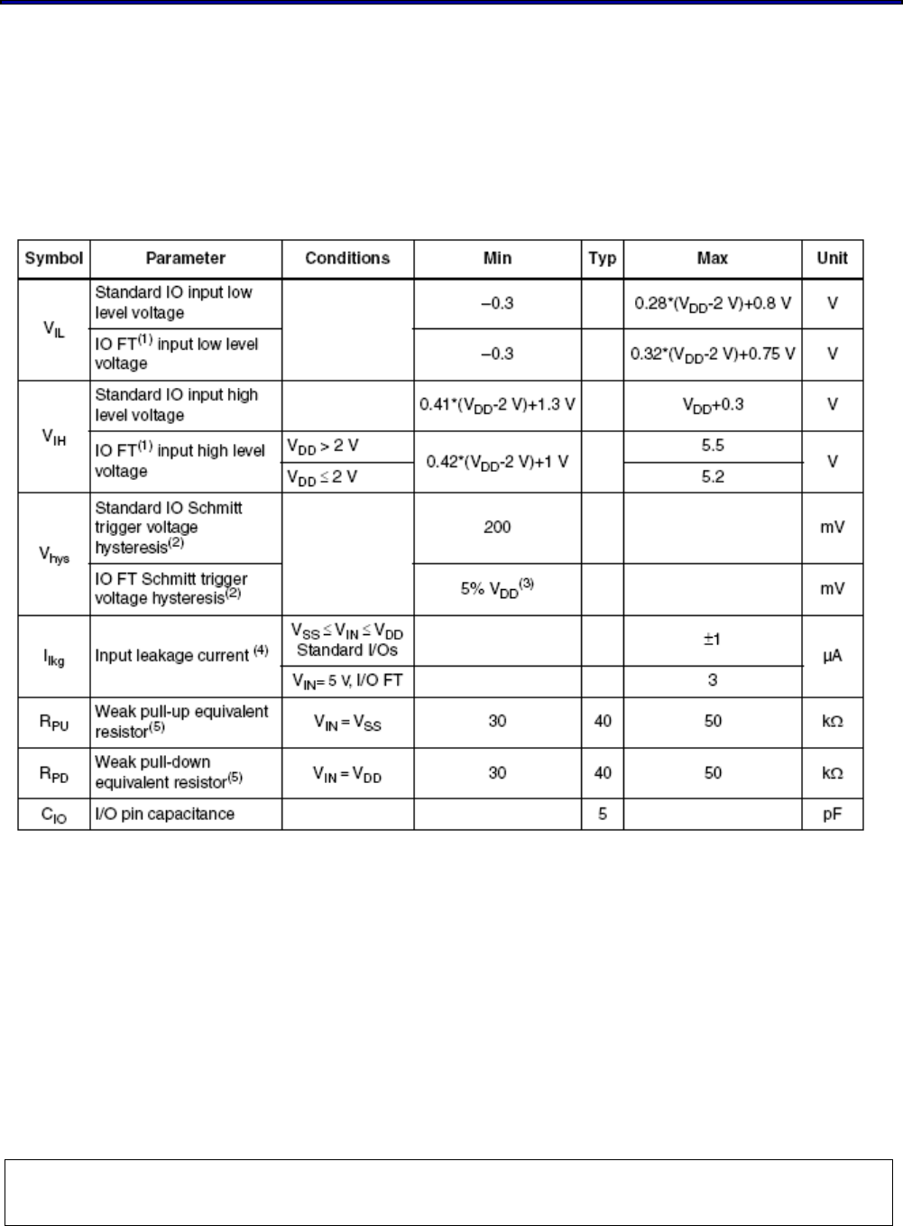
7 I/O PORT CHARACTERISTICS
Unless otherwise specified, the parameters given as below Table.
For detail information of I/O injection parameters and conditions, please refer to
STM32F205RG I/0 manual.
Table7.1 I/O static characteristics
1. FT = Five-volt tolerant. In order to sustain a voltage higher than VDD+0.3 the internal pull-
up/pull-down resistors must be disabled.
2. Hysteresis voltage between Schmitt trigger switching levels. Based on characterization, not
tested in production.
3. With a minimum of 100 mV.
4. Leakage could be higher than max. if negative current is injected on adjacent pins.
5. Pull-up and pull-down resistors are designed with a true resistance in series with a
switchable PMOS/NMOS. This MOS/NMOS contribution to the series resistance is minimum
(~10% order).
802.11b/g/n Wireless LAN WICED Module
This document is controlled and confidential under the terms of WIZNET
. 17
8 COMMUNICATIONS INTERFACE
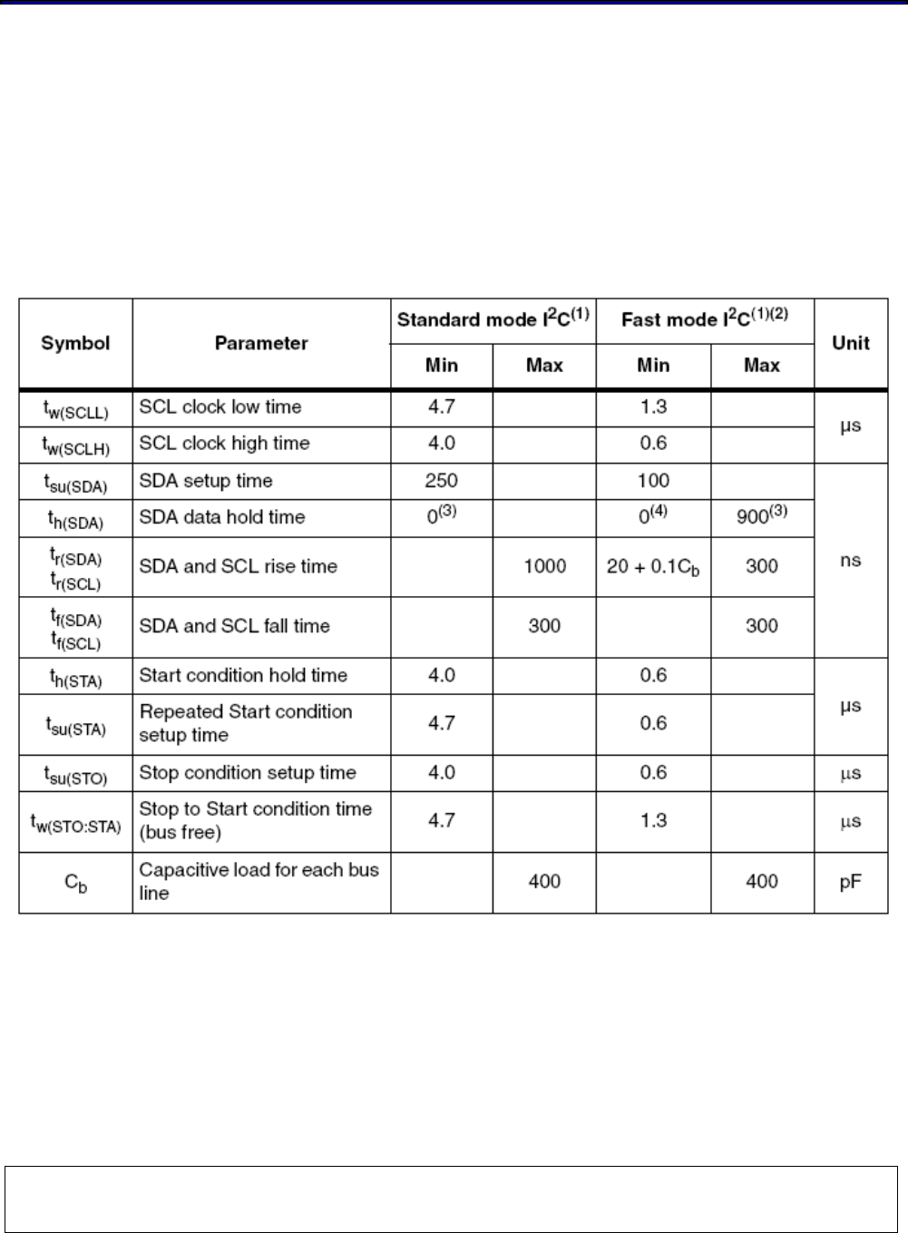
8.1 I2C Interface Characteristics
The I2C bus interfaces can operate in multi-master and slave modes. They can support the
Standard- and Fast-modes. The I2C characteristics are described in below Table. If need
detail information, please refer to STM32F205RG I/0 or Interface manual.
I2C characteristics
1. Guaranteed by design, not tested in production.
2. fPCLK1 must be higher than 2 MHz to achieve standard mode I2C frequencies. It must be higher
than 4 MHz to achieve the fast mode I2C frequencies and it must be a multiple of 10 MHz in order
to reach the I2C fast mode maximum clock speed of 400 kHz
3. The maximum hold time of the Start condition has only to be met if the interface does not stretch
the low period of SCL signal.
4. The device must internally provide a hold time of at least 300ns for the SDA signal in order to
bridge the undefined region of the falling edge of SCL.
802.11b/g/n Wireless LAN WICED Module
This document is controlled and confidential under the terms of WIZNET
. 18
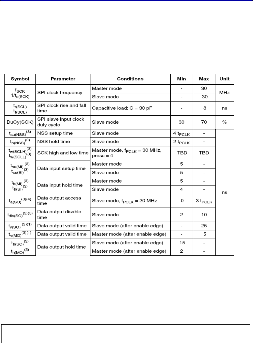
8.2 SPI / I2S interface characteristics
Unless otherwise specified, the SPI /I2S parameters are given in below Table.
Refer to STM32F205RG Datasheet : I/O port characteristics for more details on the
input/output alternate function characteristics (NSS, SCK, MOSI, MISO for SPI and WS, CK,
SD for I2S).
SPI characteristics
1. Remapped SPI1 characteristics to be determined.
2. TBD stands for “to be defined”.
3. Based on characterization, not tested in production.
4. Min time is for the minimum time to drive the output and the max time is for the maximum time to
validate the data.
5. Min time is for the minimum time to invalidate the output and the max time is for the maximum time
to put the data in Hi-Z
802.11b/g/n Wireless LAN WICED Module
This document is controlled and confidential under the terms of WIZNET
. 19
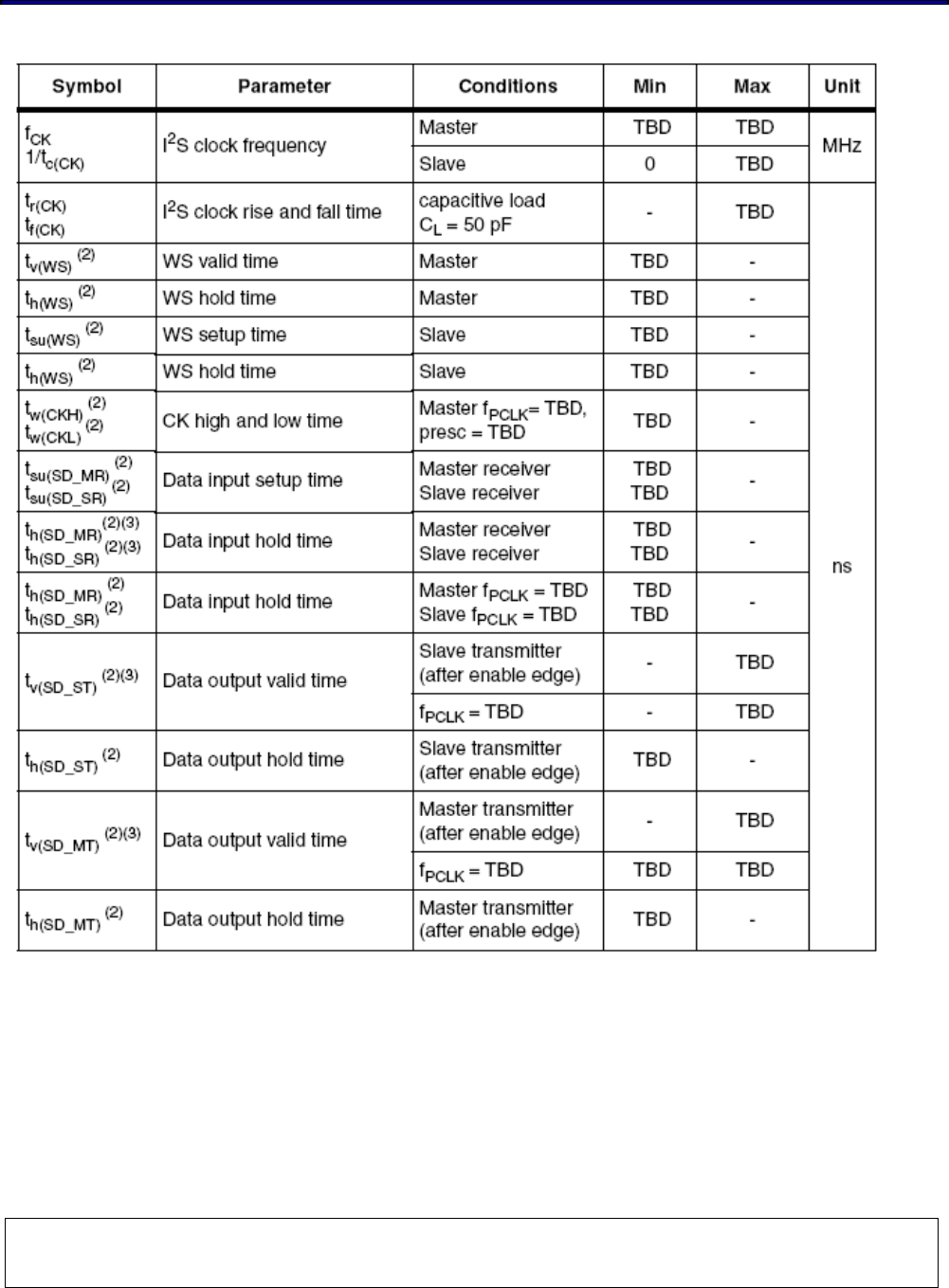
I2S characteristics
1. TBD stands for “to be defined”.
2. Based on design simulation and/or characterization results, not tested in production.
3. Depends on fPCLK. For example, if fPCLK=8 MHz, then TPCLK = 1/fPLCLK =125 ns.
802.11b/g/n Wireless LAN WICED Module
This document is controlled and confidential under the terms of WIZNET
. 20
8.3 UART interface characteristics
WM-N-BM-14 Module have two universal synchronous/asynchronous receiver transmitters,
USART1 and USART2. The USART1 can communicate at speeds of up to 7.5 Mbit/s. And
the USAR2 interfaces communicate at up to 3.75 Mbit/s.
If need more detail information, please refer to STM32F205RG I/0 or Interface manual.
9 DIMENSIONS, WEIGHT AND MOUNTING
The following paragraphs provide the requirements for the size, weight and mounting of the
WM-N-BM-14 module.
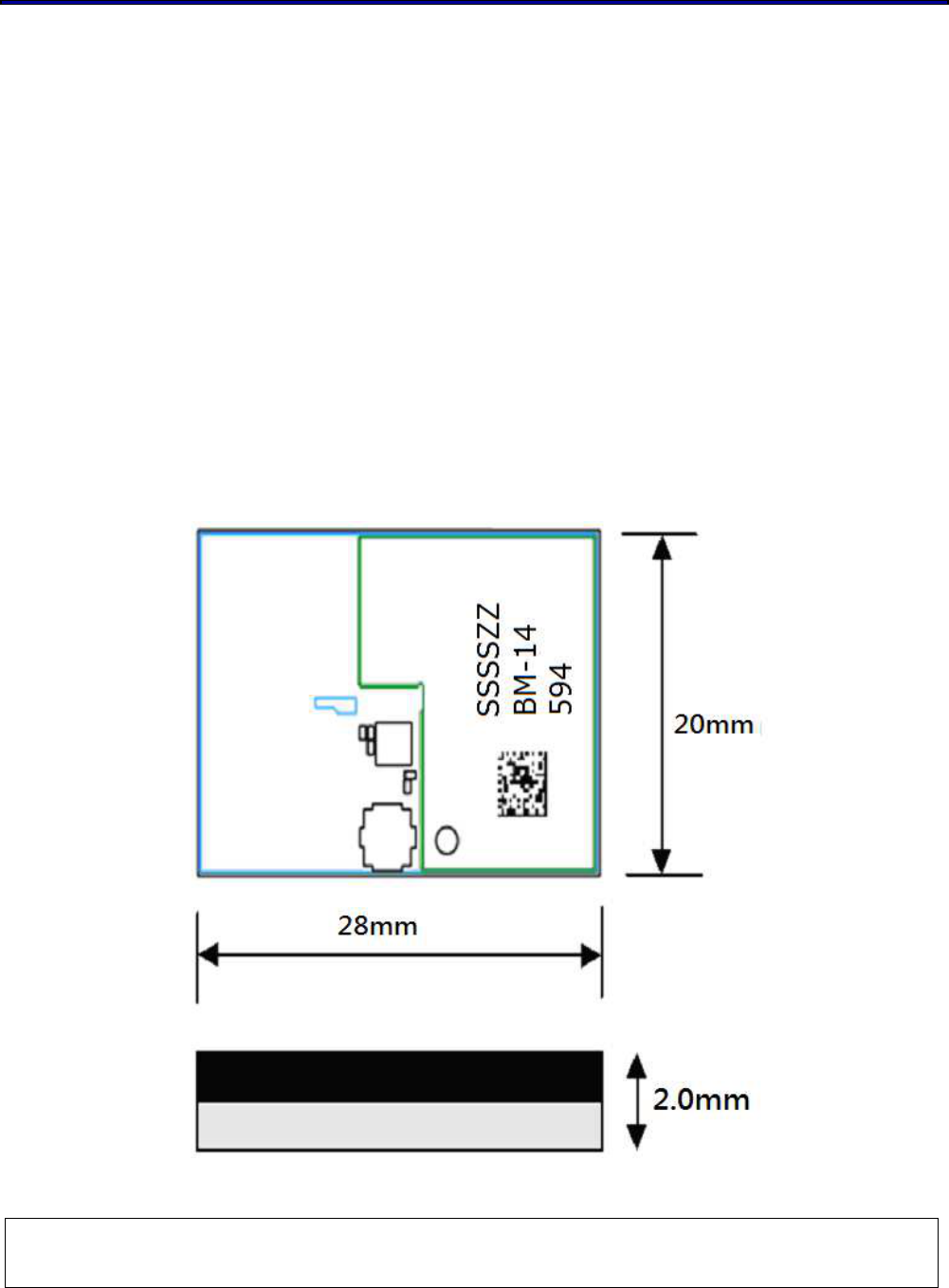
9.1 Dimensions
The size and thickness of the WM-N-BM-14 module is “28 mm (W) x 20 mm (L) x 2.0 mm (H)
+/- 0.1mm “ (Including metal shielding)
802.11b/g/n Wireless LAN WICED Module
This document is controlled and confidential under the terms of WIZNET
. 21
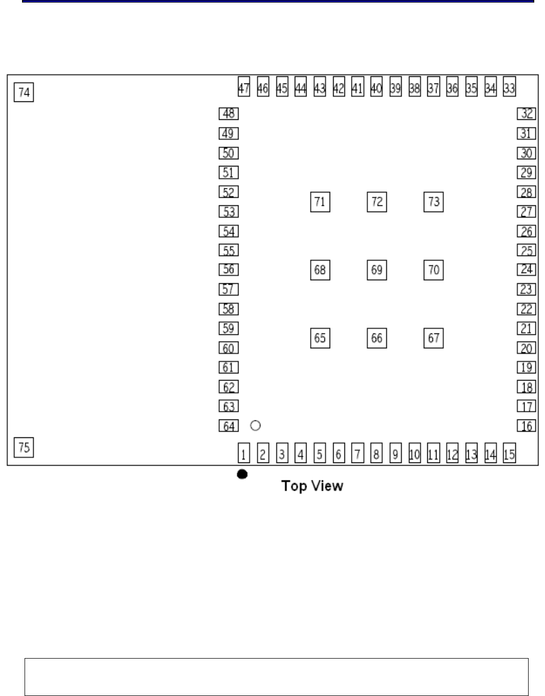
9.2 Pin Out and Pin Description
PIN OUT

802.11b/g/n Wireless LAN WICED Module
This document is controlled and confidential under the terms of WIZNET
. 22
Pin Description
Pin-Number Pin-Define Type Description
1 GND -- Ground
2 VBAT_WL I Battery supply input
3 VBAT_WL I Battery supply input
4 GND -- Ground
5 VDDIO_3V3_WL I Digital I/O supply.
6 GND -- Ground
7 WL_REG_ON -- WiFi reset .
8 NC -- --
9 NC -- --
10 NC -- --
11 NC -- --
12 NC -- --
13 GND -- Ground
14 NC -- --
15 GND -- Ground
16
WL_JTAG_TDI I/O
1. For normal operation, if JTAG is not used, this
pin can be left unconnected (NC).
2. This pin is also muxed UART_RX, which can be
enabled by software.
17 WL_JTAG_TCK I For normal operation, if JTAG is not used, this pin
can be left unconnected (NC).
18 WL_JTAG_TRST I For normal operation, if JTAG is not used, this pin
can be left unconnected (NC).
19 WL_JTAG_TMS I For normal operation, if JTAG is not used, this pin
can be left unconnected (NC).
20
WL_JTAG_TDO I/O
1. For normal operation, if JTAG is not used, this
pin can be left unconnected (NC).
2. This pin is also muxed UART_TX, which can be
enabled by software.

802.11b/g/n Wireless LAN WICED Module
This document is controlled and confidential under the terms of WIZNET
. 23
Pin-Number Pin-Define Type Description
21 MICRO_SPI1_MISO I/O SPI1_MISO
22 MICRO_SPI1_SCK I/O SPI1 CLOCK
23 MICRO_SPI1_MOSI I/O SPI1_MOSI
24 MICRO_SPI1_NSS I/O SPI1_NSS
25 GND -- Ground
26 VDD_3V3 I Power supply for I/O and the internal regulator
27 VDD_3V3 I Power supply for I/O and the internal regulator
28 GND -- Ground
29 MICRO_UART2_RTS I/O MICRO_UART2_RTS
30 MICRO_UART2_CTS I/O MICRO_UART2_CTS
31 MICRO_UART2_RXD I/O MICRO_UART2_RXD
32 MICRO_UART2_TXD I/O MICRO_UART2_TXD
33 TESTMODE I/O GPIO pin
34 MICRO_RST_N I MICRO reset pin
35 MICRO_I2C1_SCL I/O the standard I2C communication protocol
36 MICRO_I2C1_SDA I/O the standard I2C communication protocol
37 GND -- Ground
38 VBAT_MICRO I Power supply when VDD_3V3 is not present.
39 GND -- Ground
40 MICRO_GPIO1 I/O GPIO pin
41 MICRO_GPIO2 I/O GPIO pin
42 MICRO_GPIO3 I/O GPIO pin
43 MICRO_GPIO5 I/O GPIO pin
44 MICRO_GPIO6 I/O GPIO pin
45 MICRO_GPIO7
/ I2S3_SD I/O GPIO pin / also can be used on I2S3_SD
46 MICRO_GPIO8
/ I2S3_MCK I/O GPIO pin / also can be used on I2S3_MCK
47 MICRO_GPIO9 I/O GPIO pin
48 MICRO_GPIO12 I/O GPIO pin
49 MICRO_GPIO13 I/O GPIO pin

802.11b/g/n Wireless LAN WICED Module
This document is controlled and confidential under the terms of WIZNET
. 24
Pin-Number Pin-Define Type Description
50 MICRO_GPIO14 I/O GPIO pin
51 MICRO_JTAG_TRST I For normal operation, if JTAG is not used, this pin
can be left unconnected (NC)
52 MICRO_JTAG_TDO
/ I2S3_SCK I/O
1. For normal operation, if JTAG is not used, this
pin can be left unconnected (NC)
2. also can be used on I2S3_SCK
53 MICRO_JTAG_TDI
/ I2S3_WS I/O
1. For normal operation, if JTAG is not used, this
pin can be left unconnected (NC)
2. also can be used on I2S3_WS
54 MICRO_JTAG_TMS I For normal operation, if JTAG is not used, this pin
can be left unconnected (NC)
55 MICRO_JTAG_TCK I For normal operation, if JTAG is not used, this pin
can be left unconnected (NC)
56 BTCX_STATUS -- Multiplexed BT_Coex pin
57 BTCX_RF-ACTIVE -- Multiplexed BT_Coex pin
58 BTCX_TXCONF -- Multiplexed BT_Coex pin
59 GND -- Ground
60 WL_SLEEP_CLK I Input pin for optional high- precision 32.768kHz
Clock(Sleep Clock).
61 MICRO_UART1_RTS I/O Active-low request-to-send signal for UART
interface
62 MICRO_UART1_CTS I/O Active-low clear-to-send signal for UART interface
63 MICRO_UART1_RXD I/O Serial data input for UART interface
64 MICRO_UART1_TXD I/O Serial data output for UART interface
65 ~ 73 GND -- Ground
802.11b/g/n Wireless LAN WICED Module
This document is controlled and confidential under the terms of WIZNET
. 25
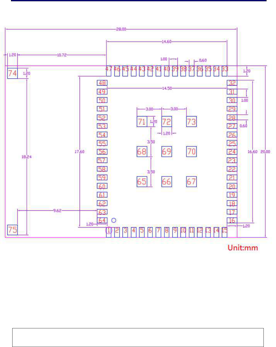
10 RECOMMEND FOOTPRINT
802.11b/g/n Wireless LAN WICED Module
This document is controlled and confidential under the terms of WIZNET
. 26
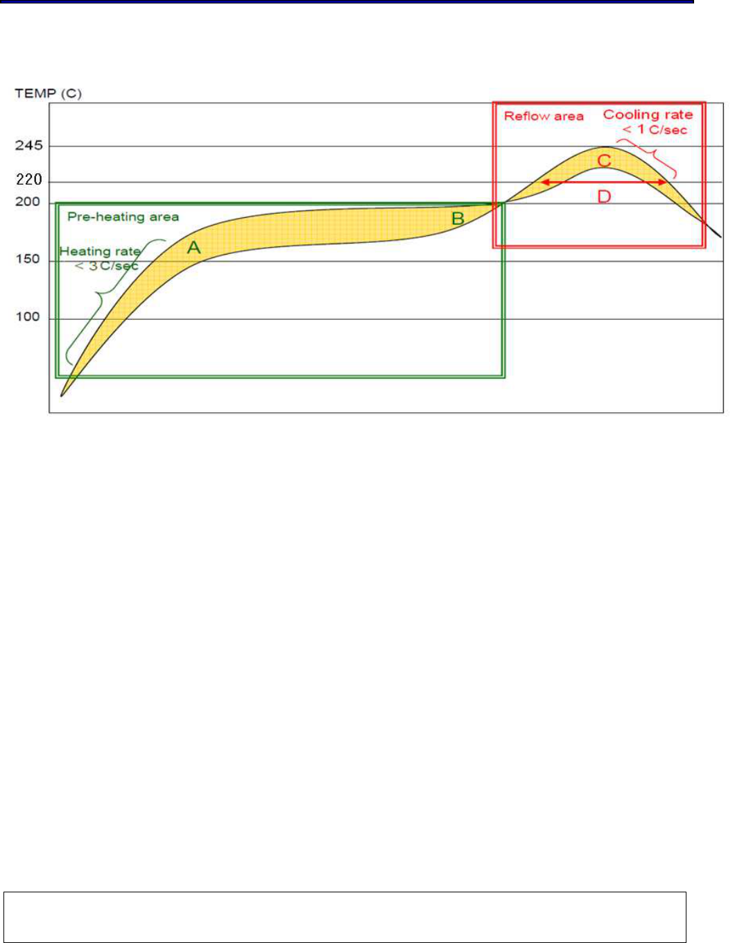
11 RECOMMEND REFLOW PROFILE
A-B. Temp.: 150~200℃; soak time:60~120sec.
C. Peak temp: 235~245℃
D. Time above 220 ℃: 40~90sec.
Suggestion: Optimal cooling rate is <1℃/sec. from peak to 220 ℃.

802.11b/g/n Wireless LAN WICED Module
This document is controlled and confidential under the terms of WIZNET
. 27
12 ESD LEVEL
Length leader / trailer tape:
Leader tape: ≥550mm which includes ≥100mm of carrier tape with empty compartments and
covered with tape; remaining part might be of cover tape only.
Trailer tape: ≥160mm with empty compartments and covered with tape.
NOTES:
1. Material: Conductive Polystyrene (Recycle)
2. Color: Black
3. Surface reslstance: 106 Ohms/square 以下
以下以下
以下.
Cumulative tolerance per 10 pictches(P0)
is ±0.2mm.
A
0
& B
0
are measured on the plane by 0.3mm above the bottom of the pocket.
4. K
0
is measured from the Inside bottom of the pocket to the top surface of the carrier.
5. Pocket position relative to sprocket hold is measured as true position of pocket,
not sprocket hold.
Note:
1. Surface Resistivity:
Interior:109~1011Ω/SQUARE
EXTERIOR:108~1012Ω/SQUARE
2. Dimension:475*420mm
3. Tolerance:+5,0mm
4. Color:
Background : Gray
Text : Red
802.11b/g/n Wireless LAN WICED Module
This document is controlled and confidential under the terms of WIZNET
. 28
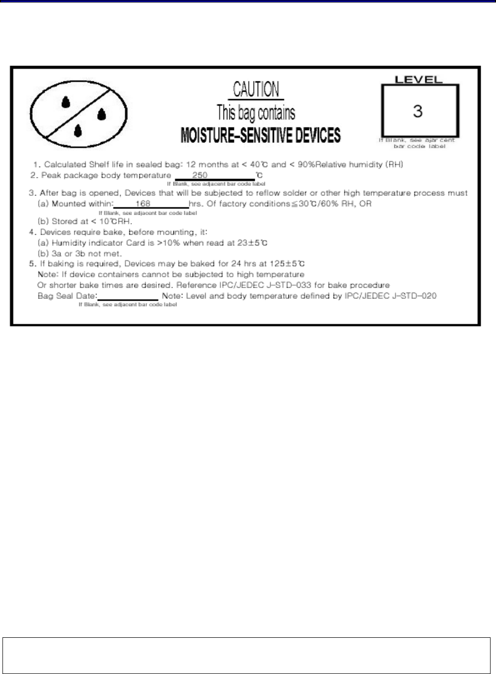
13 MSL LEVEL / STORAGE CONDITION